1
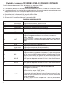
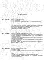
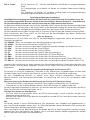
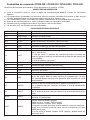
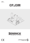
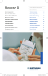
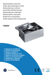
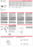
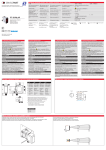
L8542371
Rev. 07/05/00
CENTRALE DI COMANDO
CONTROL UNIT
STEUEREINHEIT
CENTRALE DE COMMANDE
CENTRAL DE MANDO
CENTRALKA STEROWANIA
CP.K3-RE
CP.K3-RI
CP.K4-RE
CP.K4-RI
Libro istruzioni
Operating instructions
Betriebsanleitung
Livret d’instructions
Manual de instrucciones
Książeczka z instrukcjami
UNIONE NAZIONALE COSTRUTTORI
AUTOMATISMI PER CANCELLI, PORTE,
SERRANDE ED AFFINI
Dichiarazione CE di conformità
EC declaration of confirmity
EG-Konformitatserklarung
Déclaration CE de conformité
Declaracion CE de conformidad
Deklaracja UE o zgodności
Con la presente dichiariamo che il nostro prodotto
We hereby declare that our product
Hiermit erklaren wir, dass unser Produkt
Nous déclarons par la présente que notre produit
Por la presente declaramos que nuestro producto
Niniejszym oświadczamy że nasz produkt
CP.K3-RE / CP.K3-RI / CP.K4-RE / CP.K4-RI
è conforme alle seguenti disposizioni pertinenti:
complies with the following relevant provisions:
folgenden einschlagigen Bestimmungen entspricht:
correspond aux dispositions pertinentes suivantes:
satisface las disposiciones pertinentes siguientes:
zgodny jest z poniżej wyszczególnionymi rozporządzeniami:
Direttiva sulla compatibilità elettromagnetica (89/336/
CCE, 93/68/CEE)
EMC guidelines (89/336/EEC, 93/68/EEC)
EMV-Richtlinie (89/336/EWG, 93/68/EWG)
Directive EMV (89/336/CCE, 93/68/CEE) (Compatibilité
électromagnétique)
Reglamento de compatibilidad electromagnética (89/336/
MCE, 93/68/MCE)
Wytyczna odnośnie zdolności współdziałania elektromagnetycznego (89/336/EWG, 93/68/EWG)
Direttiva sulla bassa tensione (73/23/CEE, 93/68/CEE)
Low voltage guidelines (73/23/EEC, 93/68/EEC)
Tiefe Spannung Richtlinie (73/23/EWG, 93/68/EWG)
Directive bas voltage (73/23/CEE, 93/68/CEE)
Reglamento de bajo Voltaje (73/23/MCE, 93/68/MCE)
Wytyczna odnośnie niskiego napięcia (73/23/EWG, 93/
68/EWG)
Norme armonizzate applicate in particolare:
Applied harmonized standards, in particular:
Angewendete harmonisierte Normen, insbesondere:
Normes harmonisée utilisées, notamment:
Normas armonizadas utilzadas particularmente:
Normy standard najczęściej stosowane:
Norme armonizzate applicate in particolare:
Applied harmonized standards, in particular:
Angewendete harmonisierte Normen, insbesondere:
Normes harmonisée utilisées, notamment:
Normas armonizadas utilzadas particularmente:
Normy standard najczęściej stosowane:
EN 55014-1, EN 55014-2, EN 61000-3-2, EN 61000-3-3
EN 60204-1, EN 60335-1
Benincà Luigi, Responsabile legale.
Sandrigo, 05/04/2004.
2
Automatismi Benincà Srl
Via Capitello, 45
36066 Sandrigo (VI)
ITALIA
30
N
L
24
20
0
J2 DAS
Close
DAS 8K2
J2 DAS
Open
DAS N.C.
2AF
V AUX
0
V MO T
F1
DAS
8k2
DAS
SHIELD
ANT
ANT
24 25 26 27
SERVICE LIGHT
24Vac/15W
RADIO
POWER
S1
1
TCA
230V:T1A
120V:T2A
AMP-O
8
AMP-C
SWC-R
SWO-R
SWC
F2
SWO
STP PH OP CH PP
PGM
18 19 20 21 22
U6
SWC-R
SWO-R
SWC
SWO
COM
L1 N1
P.P
4 5 6 7 8 9 10 11 12 13 14 15 16 17
P.P.
OPEN
CLOSE
PHOT
LAMP
24Vac
STOP
24Vac
500mA max
M
COM
N
L
230Vac
50Hz
SCA
24Vac/3W
3
Centrali di comando CP.K3-RE / CP.K3-RI / CP.K4-RE / CP.K4-RI
Centrali di comando per motori 24Vdc di potenza non superiore a 120W.
AVVERTENZE GENERALI
a) L’installazione elettrica e la logica di funzionamento devono essere in accordo con le normative vigenti.
b) I conduttori alimentati con tensioni diverse, devono essere fisicamente separati, oppure devono essere
adeguatamente isolati con isolamento supplementare di almeno 1 mm.
c) I conduttori devono essere vincolati da un fissaggio supplementare in prossimità dei morsetti.
d) Ricontrollare tutti i collegamenti fatti prima di dare tensione.
e) Controllare che le impostazioni dei Dip-Switch siano quelle volute.
f) Gli ingressi N.C. non utilizzati devono essere ponticellati.
FUNZIONI INGRESSI/USCITE
4
N° Morsetti
Funzione
Descrizione
1-2
4-5
6-7
8-9
10-11
12
13
Alimentazione
Motore 24Vdc
Lampeggiante
24 Vac
SCA
COM
STOP
14
PHOT
15
16
17
18
19
OPEN
CLOSE
Passo-Passo
COM
SWO
20
SWC
21
SWO-R
22
SWC-R
24-25
Antenna
26-27
COSTA
Ingresso 230Vac 50Hz (1-Neutro/2-Fase)
Collegamento al motore 24Vdc
Collegamento lampeggiante 24Vac 40W max.
Uscita alimentazione accessori 24Vac/0,5A max.
Uscita 24 Vac per spia cancello aperto - 3W max.
Comune per tutti gli ingressi di comando.
Ingresso pulsante STOP (contatto N.C.)
Ingresso collegamento dispositivi di sicurezza, contatto N.C.
(ad es. fotocellule)
In fase di chiusura: l’apertura del contatto provoca l’arresto del motore e l’inversione istantanea della direzione di marcia dello stesso
(apre).
In fase di apertura: non attivo.
Ingresso pulsante APRE (contatto N.O.)
Ingresso pulsante CHIUDE (contatto N.O.)
Ingresso pulsante passo-passo (contatto N.O.)
Comune finecorsa.
Ingresso finecorsa APERTURA (contatto N.C.).
Ingresso finecorsa CHIUSURA (contatto N.C.). Dopo l’intercettazione del finecorsa SWC il motore continua la manovra per 1,5s (con
ingresso Costa inattivo) per garantire la perfetta battuta della porta.
Ingresso finecorsa rallentamento in apertura (contatto N.C.).
Con l’apertura di questo contatto ha inizio la fase di rallentamento
in apertura.
Ingresso finecorsa rallentamento in chiusura (contatto N.C.).
Con l’apertura di questo contatto ha inizio la fase di rallentamento
in chiusura.
Collegamento antenna scheda radioricevente ad innesto
(24-segnale/25-schermo).
Ingresso contatto costa sensibile
Costa resistiva: Jumper “DAS” chiuso
Costa meccanica: Jumper “DAS” aperto
L’intervento della costa durante la fase di apertura arresta il movimento dell’anta. Durante la fase di chiusura arresta il movimento,
inverte (apre) per 3s.
Se non si utilizza la costa: Jumper “DAS” aperto e ponticello tra i
morsetti 26-27.
J2
VAUX-0-VMOT
L1-N1
Ricevitore Radio Connettore ad innesto per ricevente radio bicanale (versioni “RE”)
Ricevente radio incorporata nelle versioni “RI”
Secondario
Collegamento avvolgimento secondario trasformatore
Primario
Collegamento avvolgimento primario trasformatore
Funzione dei Trimmer
TCA
AMP-O
AMP-C
Permette di regolare il tempo di chiusura automatica se attivata dal Dip-Switch N°1.
La regolazione varia da un minimo di 1s ad un massimo di 90s
Regola la sensibilità del sensore amperometrico di rilevamento ostacolo in fase di apertura.
Regola la sensibilità del sensore amperometrico di rilevamento ostacolo in fase di chiusura.
La regolazione dei trimmer AMP-O e AMP-C deve essere effettuata nel rispetto delle
normative vigenti.
In caso rilevamento ostacolo:
In fase di apertura ferma il movimento.
In fase di chiusura ferma e riapre l’anta per circa 3s.
Funzione Dip-Switch
DIP 1 “TCA”
Abilita o disabilita la chiusura automatica.
Off: chiusura automatica disabilitata
On: chiusura automatica abilitata
DIP 2 “PRELAM.”
Abilita o disabilita il prelampeggio
Off: Prelampeggio disabilitato
On: Prelampeggio abilitato. Il lampeggiante si attiva 3s prima della partenza del
motore.
DIP 3 “UP”
Abilita o disabilita la funzione “Uomo Presente”
Off: Funzione Uomo Presente disattivata.
On: Funzione Uomo Presente attivata.
Attivi solo i comandi APRE/CHIUDE: la pressione su questi pulsanti deve essere
mantenuta per tutta la durata della manovra (movimento controllato a vista).
Ingressi PHOT e P.P. e COSTA disabilitati.
Sensore amperometrico e STOP attivo.
DIP 4 “P.P. Mod”
Seleziona la modalità di funzionamento del ”Pulsante P.P.” e del trasmettitore.
Off: Funzionamento: APRE > STOP > CHIUDE > STOP >
On: Funzionamento: APRE > CHIUDE > APRE >
DIP 5 “Fast AMP ”
Abilita o disabilita la funzione amperometrica rapida.
Off: In chiusura il sensore amperometrico sente la rapidità di variazione di corrente,
indipendentemente dalla soglia di intervento regolata con il trimmer, e risponde in
modo rapido ad un ostacolo.
L’abilitazione di questa funzione rende maggiormente sensibile il sensore
amperometrico, aumentando il grado di sicurezza dell’automazione.
Richiede pertanto una porta perfettamente bilanciata e periodicamente controllata
per non incorrere in interventi del sensore indesiderati.
On: Funzione disabilitata. Il tempo di reazione del sensore amperometrico al
contatto con l’ostacolo è normale.
DIP 6 “COND.”
Abilita o disabilita la funzione condominiale.
Off: Funzione condominiale disabilitata.
On: Funzione condominiale abilitata. L’impulso P.P. o del trasmettitore non ha
effetto durante la fase di apertura e durante la fase TCA (se attivata).
DIP 7 “SoftSTART”
Abilita o disabilita la funzione di avvio rallentato.
Off: Funzione disabilitata.
On: Funzione abilitata. I primi 3s della manovra vengono eseguiti a velocità ridotta.
Si evitano in questo modo eccessive sollecitazioni alla meccanica.
5
DIP 8 “Radio”
Solo per versioni “RI” . Abilita o disabilita i trasmettitori a codice programmabile
On: Ricevitore radio abilitato esclusivamente ai trasmettitori a codice variabile
(rolling-code).
Off: Ricevitore abilitato a trasmettitori codice variabile (rolling-code) e
programmabile (autoapprendimento e dip/switch) .
Regolazione della velocità motore
ATTENZIONE! Questa regolazione influisce sul grado di sicurezza dell’automazione.
Verificare che la forza applicata sull’anta sia conforme con quanto previsto dalle normative vigenti.
Ogni modifica della velocità richiede una nuova taratura del sensore amperometrico.
Sul trasformatore di alimentazione è presente un connettore Faston (VMOT) la cui posizione determina la
velocità del motore. Di default il Faston VMOT è posizionato sul secondario 30V (velocità alta).
Se si desidera una velocità inferiore posizionare il Faston VMOT su 20V.
Il secondario 24V del trasformatore è riservato per l’ingresso di alimentazione accessori VAUX.
Posizionando il Faston VMOT su 20V si riduce anche la velocità del motore durante le fasi di
rallentamento.
Diagnostica LED
La centrale dispone di una serie di LED di autodiagnosi che consentono il controllo di tutte le funzioni:
Led POWER
Lampeggia a segnalare la presenza di alimentazione di rete
Led STOP
Si spegne con l’attivazione del pulsante STOP
Led PHOT
Si spegne con fotocellule non allineate o in presenza di ostacoli
Led OPN
Si accende con l’attivazione del pulsante OPEN
Led CLS
Si accende con l’attivazione del pulsante CLOSE
Led PP
Si accende con l’attivazione del pulsante PP
Led SWO
Si spegne con l’attivazione del finecorsa di apertura SWO
Led SWC
Si spegne con l’attivazione del finecorsa di chiusura SWC
Led SWO-R
Si spegne con l’attivazione del finecorsa di rallentamento apertura SWO-R
Led SWC-R
Si spegne con l’attivazione del finecorsa di rallentamento chiusura SWC-R
La centrale inoltre, prima di ogni manovra, esegue un controllo di corretto funzionamento. Se questo
controllo non viene superato il motore viene arrestato ed il LED Power segnala l’anomalia lampeggiando
velocemente.
Configurazione ricevitore incorporato (solo versioni “RI”)
La centrale è dotata di un modulo radio incorporato per la ricezione di telecomandi sia a codice fisso che a
codice variabile (vedi funzioni dip-switch 8), con frequenza di 433.92MHz.
Per utilizzare un telecomando è prima necessario apprenderlo, la procedura di memorizzazione è illustrata
di seguito, il dispositivo è in grado di memorizzare fino a 64 codici diversi.
Memorizzazione di un nuovo trasmettitore con attivazione funzione P.P.
- Premere 1 volta il pulsante PGM per 1s, il LED Power inizia a lampeggiare con 1s di pausa.
- Premere entro 10s il pulsante del trasmettitore che si desidera memorizzare con funzione P.P.
Per uscire dalla programmazione, attendere 10s o premere il pulsante PGM per 1s, il LED Power riprende
a lampeggiare normalmente con pausa di 3s.
Cancellazione di tutti i trasmettitori dalla memoria
- Mantenere premuto il pulsante PGM per 15s, il LED Power inizia al lampeggiare velocemente e si spegne
a cancellazione avvenuta.
- Rilasciare il pulsante PGM, la memoria è stata cancella ed il LED Power riprende a lampeggiare
normalmente con pausa di 3s.
NOTA:
I trasmettitori vengono memorizzati su un memoria EPROM (U6) che può essere rimossa e reinserita in una
nuova centrale in caso di sostituzione.
Per motivi di sicurezza, non è possibile memorizzare trasmettitori durante le fasi apertura/chiusura del
motore.
Se entrando nella procedura di memorizzazione dei trasmettitori il LED Power emette un lampeggio lungo e
si spegne, significa che la memoria della ricevente è piena e non è possibile memorizzare altri trasmettitori
o che il trasmettitore utilizzato non è compatibile.
6
Control units CP.K3-RE / CP.K3-RI / CP.K4-RE / CP.K4-RI
Control units for 24Vdc motors with powers under 120W.
GENERAL RULES
a) The electrical installation and operating logic must comply with statutory regulations.
b) Cables of different voltages must be physically separated or otherwise adequately screened with
secondary insulation of at least 1 mm.
c) Cables must be secured by additional clamps next to their terminals.
d) Control all wiring connections are correct before powering.
e) Check the Dip-Switch settings are correct.
f) Unused N.C. inputs must be jumpered.
INPUT/OUTPUT FUNCTIONS
Terminals
Function
1-2
4-5
6-7
8-9
10-11
12
13
Power
24Vdc motor
Beacon
24 Vac
SCA
COM
STOP
14
15
16
17
18
19
20
21
22
24-25
26-27
J2
VAUX-0-VMOT
L1-N1
Description
230Vac 50Hz input (1-Neutral/2-Live)
24Vdc motor connection
24Vac max 40W beacon connection
24Vac/max 0.5A accessory power connection
24 Vac connection for gate open light – max 3W
Common for all control signal inputs.
STOP button input (N.C. contact)
Safety input, N.C. contact (e.g. photocells)
During closing: when the contact opens the motor is stopped and
PHOT
the stroke direction is reversed immediately (i.e. opening).
During opening: disabled.
OPEN
OPEN button input (N.O. contact)
CLOSE
CLOSE button input (N.O. contact)
PP Step-by-step Step-by-step button input (N.O. contact)
COM
Common connection for travel limit switches.
SWO
OPEN travel limit switch input (N.C. contact).
CLOSE travel limit switch input (N.C. contact). When the SWC limit
SWC
switch trips the motor continues running for 1.5 sec (with no Proximity signal) to make sure the gate is firmly shut.
Open slowdown travel limit switch input (N.C. contact).
SWO-R
When this contact opens it starts the open slowdown cycle.
Close slowdown travel limit switch input (N.C. contact).
SWC-R
When this contact opens it starts the close slowdown cycle.
Plug-in radio receiver antenna board connections
Antenna
(24-signal/25-screen).
Edge contact input
Electric edge: Jumper “DAS” bridged
Mechanical edge: Jumper “DAS” open
EDGE
If the edge trips during opening the gate stops. If the gate is closing it will change direction to open for 3 sec.
Edge not used: Jumper “DAS” open and jumper across terminals
26-27.
Radio receiver
Socket for two channel radio receiver (“RE” versions)
The RI versions have a built-in radio receiver
Secondary
Terminal for secondary circuit of transformer
Primary
Terminal for primary circuit of transformer
7
Trimmer functions
TCA
AMP-O
AMP-C
Adjustment of the automatic close time if enabled by Dip-Switch 1.
Adjustment ranges from 1 sec to max 90 sec
Adjustment of the amperometric sensor obstacle detection sensitivity during the open
cycle.
Adjustment of the amperometric sensor obstacle detection sensitivity during the close
cycle.
Adjustment of trimmers AMP-O and AMP-C must comply with statutory
regulations.
If an obstacle is detected:
When opening, the gate is stopped.
When closing, the gate stops and opens for about 3 sec.
Dip-Switch functions
DIP 1 “TCA”
Enables or disables automatic closing.
Off: automatic closing disabled
On: automatic closing enabled
DIP 2 “PRELAM.”
Enables or disables pre-flashing
Off: Pre-flash disabled
On: Pre-flash enabled. The beacon flashes for 3 sec before the motor starts.
DIP 3 “UP”
Enables or disables the “Manned” function
Off: Manned function disabled.
On: Manned function enabled.
Only the OPEN/CLOSE controls are enabled: these buttons must be kept
pressed throughout the whole cycle (i.e. direct control of gate actions).
PHOT and P.P. inputs and PROXIMITY disabled.
Amperometric sensor and STOP enabled.
DIP 4 “P.P. Mod”
Selects the operating mode for the ” P.P. button” and the transmitter.
Off: operating sequence: OPEN > STOP > CLOSE > STOP >
On: operating sequence: OPEN > CLOSE > OPEN >
DIP 5 “Fast AMP ”
Enables or disables the rapid amperometric function.
Off: in the close cycle the amperometric sensor detects the speed of variation
in current, regardless of the threshold adjustment by the trimmer, and reacts
rapidly to an obstacle.
This function raises the sensitivity of the amperometric sensor, increasing the
safety of the gate automation.
To use this function the gate has to be perfectly balanced and routinely checked
to avoid false sensor trips.
On: Function disabled. The reaction time of the amperometric sensor when an
obstacle is detected is normal.
DIP 6 “COND.”
Enables or disables the high traffic function.
Off: High traffic function disabled.
On: High traffic function enabled. The P.P. (Step-by-step) or transmitter signal is
ignored during the open cycle and the TCA cycle (if enabled).
DIP 7 “SoftSTART”
Enables or disables soft start function.
Off: Function disabled.
On: Function enabled. The first 3 sec of the stroke are at a slower speed. This
avoids unduly stressing the mechanics.
DIP 8 “Radio”
Only for “RI” versions. Enables or disables transmitters with programmable
codes
On: Radio receiver enabled exclusively for rolling-code transmitters.
Off: Receiver enabled for both rolling-code and programmable transmitters
(self-learn and dip-switch) .
8
Motor speed adjustment
CAUTION! This adjustment strongly affects the safety of the gate automation.
Make sure that the gate thrust complies with statutory regulations.
If the gate speed is changed the amperometric sensor must be calibrated accordingly.
The power transformer has a Faston connector (VMOT) which can be used to set the motor speed. The
VMOT Faston is factory set on the 30V secondary circuit (i.e. high speed).
To reduce the speed set the VMOT Faston on 20V.
The 24V secondary circuit of the transformer is reserved for powering VAUX accessories.
By setting the VMOT Faston on 20V the motor speed is also reduced during the slowdown cycles.
Diagnostic LED’s
The control unit has a series of LED’s to provide diagnostic information on the status of all the functions:
POWER LED
Blinks to signal the unit is powered
STOP LED
ON when the STOP button is pressed
PHOT LED
OFF when the photocells are not aligned or obstructed
OPN LED
ON when the OPEN button is pressed
CLS LED
ON when the CLOSE button is pressed
PP LED
ON when the PP (Step-by-step) button is pressed
SWO LED
OFF when the SWO open travel limit switch trips
SWC LED
OFF when the SWC close travel limit switch trips
SWO-R LED
OFF when the SWO-R open slowdown travel limit switch trips
SWC-R LED
OFF when the SWC-R close slowdown travel limit switch trips
Before any action the control unit runs a check-up on its correct operation. If any error is found the motor
is stopped and the Power LED blinks rapidly to signal there is a fault.
Configuration with built-in receiver (only “RI” versions)
The control unit is fitted with a built-in radio module for receiving remote controls both with fixed codes
and variable codes (see dip-switch 8 functions), with a frequency of 433.92MHz.
For a transmitter to be used, the module first has to self-learn its code. The memorise procedure is
illustrated below, the module can memorise up to 64 different codes.
Memorising a new transmitter by activating the P.P. function
- Press the PGM button once for 1sec and the Power LED will start blinking at 1 sec intervals.
- Press the transmitter button within 10 sec to memorise with the P.P. (Step-by-step) function
To exit the programming procedure wait 10 sec or press the PGM button for 1 sec, the Power LED will
return to normal blinking at 3 sec intervals.
Cancelling all transmitters from the memory
- Keep the PGM button pressed for 15 sec, the Power LED will start blinking rapidly and when it goes out
the memory has been erased.
- Release the PGM button, the memory has been cancelled and the Power LED will return to normal
blinking at 3 sec intervals.
N.B.:
The transmitters are stored on an EPROM (U6) memory board that can be removed and installed in a new
control unit in case of breakdown.
For safety reasons, transmitters cannot be memorised during the open/close cycles of the motor.
When entering the memorise transmitter procedure, if the Power LED gives a prolonged blink and then
goes out, this signals that the receiver memory is full and no other transmitters can be memorised or that
the transmitter is not compatible.
9
Steuerzentralen CP.K3-RE / CP.K3-RI / CP.K4-RE / CP.K4-RI
Steuerzentralen für Motoren 24Vdc mit einer Leistung bis 120 W.
ALLGEMEINE HINWEISE
a) Die Elektroinstallation und die Funktionslogik müssen den einschlägigen Normen entsprechen.
b) Verschiedene Spannungen führende Leiter müssen physisch getrennt oder mit einer zusätzlichen Isolierung
von mindestens 1 mm versehen sein.
c) In der Nähe der Klemmen müssen die Leiter zusätzlich fixiert werden.
d) Vor dem Zuschalten der Spannung alle Anschlüsse nochmals prüfen.
e) Kontrollieren, ob die Dip-Switches wie gewünscht eingestellt sind.
f) Die nicht verwendeten, normalerweise geschlossenen Eingänge müssen überbrückt werden.
FUNKTIONEN DER EIN-/AUSGÄNGE
Klemmen
Funktion
Beschreibung
1-2
4-5
6-7
8-9
10-11
12
13
Versorgung
Motor 24Vdc
Blinkleuchte
24 Vac
SCA
COM
STOPP
14
PHOT
15
16
17
18
19
OPEN
CLOSE
PP Schrittschaltung
COM
SWO
20
SWC
21
SWO-R
22
SWC-R
24-25
Antenne
26-27
KONTAKTLEISTE
Eingang 230Vac 50Hz (1-Nullleiter/2-Phase)
Anschluss an Motor 24Vdc
Anschluss Blinkleuchte 24Vac 40W max.
Ausgang Zubehörspeisung 24Vac/0,5A max.
Ausgang 24 Vac für Kontrolllampe „Offenes Tor“. - 3W max.
Gemeinsam für alle Steuereingänge
Eingang Taste STOPP (Ruhekontakt)
Eingang für Anschluss der Sicherheitsvorrichtungen, Ruhekontakt (z.B.
Photozellen)
Während des Schließens: Bei Öffnen des Kontakts wird der Motor angehalten und seine Gangrichtung umgehend umgekehrt (Schließen).
Während des Öffnens: nicht aktiv.
Eingang Taste ÖFFNEN (Arbeitskontakt)
Eingang Taste SCHLIESSEN (Arbeitskontakt)
Eingang Taste Schrittschaltung (Arbeitskontakt)
Gemeinsam für Endschalter.
Eingang Endschalter ÖFFNEN (Ruhekontakt).
Eingang Endschalter SCHLIESSEN (Ruhekontakt). Nach Erfassen des
Endschalters SWC setzt der Motor das Manöver für 1,5s fort (bei nicht
aktivem Eingang Kontaktleiste), um das perfekte Anschlagen des Tors
zu gewährleisten.
Eingang Endschalter Verlangsamung bei Öffnen (Ruhekontakt).
Mit Öffnen dieses Kontakts beginnt die Verlangsamung während des
Öffnens.
Eingang Endschalter Verlangsamung bei Schließen (Ruhekontakt).
Mit Öffnen dieses Kontakts beginnt die Verlangsamung während des
Schließens.
Antennenanschluss Funkempfangsplatine zum Stecken (24-Signal/25Schirm).
Eingang Kontakt Näherungsleiste
Resistive Kontaktleiste: Jumper “DAS” geschlossen
Mechanische Kontaktleiste: Jumper “DAS” geöffnet
Das Auslösen der Kontaktleiste während des Öffnens hält die Bewegung des Torflügels an. Während des Schließens wird die Bewegung
angehalten und für 3s umgekehrt (Öffnen).
Bei Nichtverwendung der Leiste: Jumper “DAS” geöffnet und Brücke
zwischen den Klemmen 26-27.
10
J2
Funkempfänger
VAUX-0-VMOT Sekundärwicklung
L1-N1
Primärwicklung
Steckverbinder für 2-Kanal-Funkempfänger (Versionen “RE”)
Eingebauter Funkempfänger bei den Versionen “RI”
Anschluss Sekundärwicklung Transformator
Anschluss Primärwicklung Transformator
Funktion der Trimmer
TCA
AMP-O
AMP-C
Ermöglicht die Einstellung der automatischen Verschlusszeit, wenn mittels Dip-Switch Nr. 1
aktiviert. Die Einstellung reicht von min. 1s bis max. 90s
Regelt die Empfindlichkeit des amperometrischen Sensors zur Erkennung von Hindernissen
während des Öffnens.
Regelt die Empfindlichkeit des amperometrischen Sensors zur Erkennung von Hindernissen
während des Schließens.
Die Einstellung der Trimmer AMP-O und AMP-C muss unter Einhaltung der einschlägigen
Vorschriften erfolgen.
Wenn ein Hindernis erfasst wird:
Während des Öffnens wird die Bewegung angehalten.
Während des Schließens wird der Torflügel angehalten und für zirka 3s wieder geöffnet.
Funktion der Dip-Switches
DIP 1 “TCA”
Aktiviert oder deaktiviert das automatische Schließen.
Off: Automatisches Schließen deaktiviert
On: Automatisches Schließen aktiviert
DIP 2 “PRELAM.”
Aktiviert oder deaktiviert das Vorwarnblinken.
Off: Vorwarnblinken deaktiviert.
On: Vorwarnblinken aktiviert.
Die Blinkleuchte schaltet sich 3s vor Anlaufen des Motors ein.
DIP 3 “UP”
Aktiviert oder deaktiviert den Bedienbetrieb.
Off: Bedienbetrieb deaktiviert.
On: Bedienbetrieb aktiviert.
Nur die Steuerungen ÖFFNEN/SCHLIESSEN sind aktiv: Die Tasten müssen während
des gesamten Manövers gedrückt gehalten werden (Bewegung mit Sichtkontrolle).
Eingänge PHOT und P.P. (Schrittschaltung) und KONTAKTLEISTE deaktiviert.
Amperometrischer Sensor und STOPP aktiv.
DIP 4 “P.P. Mod” Wählt den Funktionsmodus ”Taste P.P.“ (Schrittschaltung) und des Senders.
Off: Funktion: ÖFFNEN > STOPP > SCHLIESSEN > STOPP >
On: Funktion: ÖFFNEN > SCHLIESSEN > ÖFFNEN >
DIP 5 “Fast AMP ” Aktiviert oder deaktiviert die amperometrische Schnell-Funktion.
Off: Beim Schließen fühlt der amperometrische Sensor die Schnelligkeit der
Stromschwankung, unabhängig von der mit dem Trimmer eingestellten Auslöseschwelle,
und reagiert rasch auf Hindernisse.
Die Aktivierung dieser Funktion macht den amperometrischen Sensor noch
empfindlicher und erhöht den Sicherheitsgrad der Automatisierung.
Sie erfordert folglich einen perfekt ausgewuchteten und regelmäßig kontrollierten
Torflügel, damit der Sensor nicht ungewollt ausgelöst werden kann.
On: Funktion deaktiviert. Die Ansprechzeit des amperometrischen Sensors bei Kontakt
mit einem Hindernis ist normal.
DIP 6 “COND.”
Aktiviert oder deaktiviert die Mehrbenutzerfunktion.
Off: Mehrbenutzerfunktion deaktiviert.
On: Mehrbenutzerfunktion aktiviert. Der Impuls der Schrittschaltung oder des Senders
wirkt sich nicht aus während des Öffnens oder während der TCA-Phase (sofern
aktiviert).
DIP 7 “SoftSTART” Aktiviert oder deaktiviert die Funktion des abgebremsten Anlaufs.
Off: Funktion deaktiviert.
On: Funktion aktiviert. Di ersten 3s des Manövers erfolgen bei verringerter
Geschwindigkeit. Auf diese Weise werden übermäßige Belastungen der Mechanik
vermieden.
11
DIP 8 “Radio”
Nur für Versionen “RI” . Aktiviert oder deaktiviert die Sender mit programmierbarem
Code
On: Funkempfänger ausschließlich für Sender mit variablem Code aktiviert (RollingCode).
Off: Empfänger für Sender mit variablem (Rolling-Code) und programmierbarem
(Selbstlernung und Dip-Switch) Code aktiviert.
Regelung der Motorgeschwindigkeit
ACHTUNG! Diese Regelung beeinflusst die Sicherheit der Automatisierung. Sicherstellen, dass die
am Torflügel angewandte Kraft den Vorgaben der einschlägigen Normen entspricht. Jede Änderung
der Geschwindigkeit erfordert die erneute Justierung des amperometrischen Sensors.
Am Speisetransformator befindet sich ein Faston-Verbinder (VMOT), dessen Position die Geschwindigkeit des
Motors bestimmt. Defaultmäßig ist der Faston VMOT an der Sekundärwicklung 30V (hohe Geschwindigkeit)
positioniert. Wird eine niedrigere Geschwindigkeit gewünscht, den Faston VMOT auf 20V positionieren.
Die 24V-Sekundärwicklung des Transformators ist reserviert für den Eingang der Zubehörversorgung VAUX.
Durch Positionieren des Faston VMOT auf 20V wird auch die Geschwindigkeit des Motors während der
Verlangsamungsphasen verringert.
LEDs zur Diagnose
Die Zentrale ist mit einer Reihe von LEDs für die Selbstdiagnose ausgestattet, welche die Kontrolle aller
Funktionen ermöglichen:
LED POWER Blinkt, um anzuzeigen, dass die Netzversorgung zugeschaltet ist
LED STOPP Schaltet sich bei Drücken der Taste STOPP aus
LED PHOT
Schaltet sich bei nicht gefluchteten Photozellen oder bei Vorliegen von Hindernissen aus
LED OPN
Schaltet sich bei Drücken der Taste OPEN ein
LED CLS
Schaltet sich bei Drücken der Taste CLOSE ein
LED PP
Schaltet sich bei Drücken der Taste PP (Schrittschaltung) ein
LED SWO
Schaltet sich bei Auslösen des Endschalters für Öffnen SWO aus
LED SWC
Schaltet sich bei Auslösen des Endschalters für Schließen SWC aus
LED SWO-R Schaltet sich bei Auslösen des Endschalters für Verlangsamung des Öffnens SWO-R aus
LED SWC-R Schaltet sich bei Auslösen des Endschalters für Verlangsamung des Schließens SWC-R aus
Außerdem führt die Zentrale vor jedem Manöver eine Funktionskontrolle durch. Sofern diese Kontrolle nicht
positiv ausfällt, wird der Motor angehalten und die LED für Power weist durch schnelles Blinken auf die
Anomalie hin.
Konfiguration des eingebauten Empfängers (nur Versionen “RI”)
Die Zentrale ist mit einem eingebauten Funkmodul für den Empfang von Fernbedienungen mit fixem oder
variablem Code (siehe Funktionen Dip-Switch 8), bei einer Frequenz von 433.92MHz ausgestattet.
Um eine Fernbedienung benutzen zu können, muss diese zunächst programmiert werden. Das
Speicherverfahren wird nachstehend beschrieben. Die Vorrichtung kann bis zu 64 verschiedene Codes
speichern.
Speichern eines neuen Senders mit Aktivierung der Funktion P.P. (Schrittschaltung)
- 1 Mal die Taste PGM 1s lang drücken, die LED für Power beginnt mit Abständen von 1s zu blinken.
- Innerhalb von 10s die Taste des Senders drücken, die mit der Funktion P.P. belegt werden soll.
Um den Programmierungsmodus zu verlassen, 10s abwarten oder die Taste PGM 1s lang drücken, die LED für
Power blinkt erneut normal mit Abständen von 3s.
Löschen aller Sender aus dem Speicher
- Die Taste PGM 15s lang gedrückt halten, die LED für Power beginnt schnell zu blinken und geht nach
abgeschlossenem Löschen aus.
- Nun die Taste PGM loslassen; der Speicher wurde gelöscht und die LED für Power blinkt wieder normal mit
Abständen von 3s.
NB:
Die Sender werden in einem EPROM-Speicher (U6) gespeichert, der ausgebaut und gegebenenfalls in
eine neue Zentrale eingebaut werden kann. Aus Sicherheitsgründen können die Sender nicht während des
Öffnens/Schließens des Motors gespeichert werden.
Wenn nach Zugriff auf das Speicherverfahren der Sender die LED für Power lange blinkt und dann ausgeht,
bedeutet dies, dass der Speicher des Senders voll ist und keine weiteren Sender eingespeichert werden
können, oder dass der Sender nicht kompatibel ist.
12
Logiques de commande CP.K3-RE / CP.K3-RI / CP.K4-RE / CP.K4-RI
Logiques de commande pour moteurs 24 Vcc de puissance non supérieure à 120W.
RECOMMANDATIONS GÉNÉRALES
a) L’installation électrique et la logique de fonctionnement doivent être conformes aux normes en vigueur.
b) Les conducteurs alimentés à des tensions différentes doivent être séparés physiquement ou bien, ils
doivent être isolés de manière appropriée avec une gaine supplémentaire d’au moins 1 mm.
c) Les conducteurs doivent être assurés par une fixation supplémentaire à proximité des bornes.
d) Recontrôler toutes les connexions faites avant d’alimenter la logique de commande.
e) Contrôler que les réglages des dip-switchs correspondent à la programmation désirée.
f) Les entrées N.F. non utilisées doivent être shuntées.
FONCTIONS ENTRÉES/SORTIES
N° Bornes Fonction
Description
1-2
4-5
6-7
8-9
10-11
12
13
Alimentation
Moteur 24V
Clignotant
24 Vca
SCA
COM
STOP
14
PHOT
15
16
17
18
19
OPEN
CLOSE
Pas à pas
COM
SWO
20
SWC
21
SWO-R
22
SWC-R
24-25
Antenne
26-27
BARRE
PALPEUSE
Entrée 230 Vca 50 Hz (1-Neutre/2-phase)
Connexion au moteur 24 Vcc
Connexion clignotant 24 Vca 40 W max.
Sortie alimentation accessoires 24 Vca/0,5 A max.
Sortie 24 Vca pour voyant portail ouvert – 3 W max.
Commun pour toutes les entrées de commande
Entrée touche STOP (contact N.F.)
Entrée connexion dispositifs de sécurité, contact N.F.
(par ex. photocellules)
En phase de fermeture: l’ouverture du contact provoque l’arrêt du moteur
et l’inversion instantanée de son sens de marche (ouverture)
En phase d’ouverture: non active.
Entrée touche OUVERTURE (contact N.O.)
Entrée touche FERMETURE (contact N.O.)
Entrée touche pas à pas (contact N.O.)
Commun fin de course
Entrée fin de course OUVERTURE (contact N.F.)
Entrée fin de course FERMETURE (contact N.F.) Après l’excitation du fin
de course SWC, le moteur continue la manœuvre pendant 1,5 s (avec
entrée Barre palpeuse inactive) pour garantir que la porte est parfaitement
en butée.
Entrée fin de course ralentissement en ouverture (contact N.F.)
L’ouverture de ce contact fait commencer la phase de ralentissement en
ouverture.
Entrée fin de course ralentissement en fermeture (contact N.F.)
L’ouverture de ce contact fait commencer la phase de ralentissement en
fermeture.
Connexion antenne carte récepteur radio embrochable
(24-signal/25-blindage).
Entrée contact bord sensible
Barre palpeuse à variation de résistance : Cavalier “DAS” fermé
Barre palpeuse mécanique: Cavalier “DAS” ouvert
L’intervention de la barre palpeuse durant la phase d’ouverture arrête le
mouvement du vantail. Durant la phase de fermeture, elle arrête le mouvement et l’inverse (ouverture) pendant 3 s.
Si la barre palpeuse n’est pas utilisée: Cavalier “DAS” ouvert et shunt
entre les bornes 26-27.
13
J2
Récepteur
Radio
VAUX-0-VMOT Secondaire
L1-N1
Primaire
Connecteur embrochable pour récepteur radio bicanal (versions “RE”)
Récepteur radio incorporé dans les versions“RI”
Connexion bobinage secondaire transformateur
Connexion bobinage primaire transformateur
Fonction des Trimmers
TCA
AMP-O
AMP-C
Permet de régler le temps de fermeture automatique si elle est activée par le dip-switch N°1.
Le réglage varie d’un minimum d’1 s à un maximum de 90 s
Règle la sensibilité du capteur ampèremétrique de détection des obstacles en phase
d’ouverture.
Règle la sensibilité du capteur ampèremétrique de détection des obstacles en phase de
fermeture. Le réglage des trimmers AMP-O et AMP-C doit être effectué dans le respect
des normes en vigueur.
En cas de détection d’obstacle :
En phase d’ouverture, il arrête le mouvement :
En phase de fermeture, arrête et rouvre le vantail pendant environ 3 s.
Fonction dip-switchs
DIP 1 “TCA”
Active ou désactive la fermeture automatique.
Off : fermeture automatique désactivée
On : fermeture automatique activée
DIP 2 “PRELAM.” Active ou désactive le préclignotement
Off : Préclignotement désactivé
On : Préclignotement activé. Le clignotant s’active 3 s avant le démarrage du
moteur.
DIP 3 “UP”
Active ou désactive la fonction commande par action maintenue.
Off : Fonction commande par action maintenue désactivée.
On : Fonction commande par action maintenue activée.
Seules les commandes OUVERTURE/FERMETURE sont actives : la pression sur ces
touches doit être maintenue pendant toute la durée de la manœuvre (mouvement
contrôlé visuellement).
Entrées PHOT et P.P. et BARRE PALPEUSE désactivées.
Capteur ampèremétrique et STOP actif.
DIP 4 “P.P. Mod”
Sélectionne le mode de fonctionnement de la “Touche P.P.” et de l’émetteur.
Off : Fonctionnement : OUVERTURE > STOP > FERMETURE > STOP >
On : Fonctionnement : OUVERTURE > FERMETURE > OUVERTURE >
DIP 5 “Fast AMP” Active ou désactive la fonction ampèremétrique rapide.
Off : En fermeture, le capteur ampèremétrique sent la rapidité de variation de
courant, indépendamment du seuil d’intervention réglée au moyen du trimmer, et
répond rapidement en cas d’obstacle.
L’activation de cette fonction rend le capteur ampèremétrique encore plus sensible,
en augmentant ainsi le degré de sécurité de l’automatisme.
Elle demande par conséquent un vantail parfaitement équilibré et contrôlé
périodiquement pour ne pas risquer des interventions non désirées du capteur.
On : Fonction désactivée. Le temps de réaction du capteur ampèremétrique au
contact avec l’obstacle est normal.
DIP 6 “COND.”
Active ou désactive le fonctionnement collectif
Off : Fonctionnement collectif désactivé.
On : Fonctionnement collectif activé. L’impulsion P.P. ou de l’émetteur n’a pas d’effet
durant la phase d’ouverture ni durant la phase TCA (si elle est activée).
DIP 7 “SoftSTART” Active ou désactive la fonction de démarrage ralenti.
Off : Fonction désactivée.
On : Fonction activée. Les 3 premières secondes de manœuvre sont effectuées à
vitesse réduite. On évite de cette manière de soumettre la partie mécanique à des
efforts excessifs.
DIP 8 “Radio”
Uniquement pour les versions “RI”. Active ou désactive les émetteurs à code
14
programmable
On : Récepteur radio compatible exclusivement avec les émetteurs à code variable
(rolling-code).
Off : Récepteur radio compatible avec les émetteurs à code variable (rolling-code) et
programmable (auto-apprentissage et dip-switch).
Réglage de la vitesse moteur
ATTENTION ! Ce réglage influence le degré de sécurité de l’automatisme.
Vérifier que la force appliquée sur le portail est conforme aux prescriptions des normes en vigueur.
Toute modification de la vitesse demande un nouvel étalonnage du capteur ampèremétrique.
Sur le transformateur se trouve un connecteur Faston (VMOT) dont la position détermine la vitesse du
moteur. Par défaut, le Faston VMOT est positionné sur le secondaire 30 V (vitesse élevée).
Si l’on souhaite une vitesse inférieure, positionner le Faston VMOT sur 20 V.
Le secondaire 24 V du transformateur est réservé à l’entrée d’alimentation accessoires VAUX.
En positionnant le Faston VMOT sur 20 V on réduit aussi la vitesse du moteur durant les phases de
ralentissement.
Leds de diagnostic
La logique de commande dispose d’une série de leds d’autodiagnostic qui permettent le contrôle de toutes
les fonctions :
Led POWER
Clignote pour signaler la présence de l’alimentation de secteur
Led STOP
S’éteint avec l’activation de la touche STOP
Led PHOT
Elle s’éteint en cas de photocellules non alignées ou en présence d’obstacles
Led OPN
Elle s’allume avec l’activation de la touche OPEN
Led CLS
Elle s’allume avec l’activation de la touche CLOSE
Led PP
Elle s’allume avec l’activation de la touche PP
Led SWO
Elle s’éteint avec l’activation du fin de course d’ouverture SWO
Led SWC
Elle s’éteint avec l’activation du fin de course de fermeture SWC
Led SWO-R
Elle s’éteint avec l’activation du fin de course de ralentissement ouverture SWO-R
Led SWC-R
Elle s’éteint avec l’activation du fin de course de ralentissement fermeture SWC-R
De plus, la logique de commande, avant chaque manœuvre, effectue un contrôle de fonctionnement
correct. Si le contrôle décèle une anomalie, le moteur est arrêté et la LED Power signale l’anomalie par un
clignotement rapide.
Configuration récepteur incorporé (versions “RI” uniquement)
La logique de commande est munie d’un module radio incorporé pour la réception d’émetteurs aussi bien à
code fixe qu’à code variable (voir fonctions dip-switch 8), à la fréquence de 433,92 MHz.
Pour utiliser un émetteur, il faut d’abord l’enregistrer, la procédure de mémorisation est illustrée ci-après, le
dispositif est en mesure de mémoriser jusqu’à 64 codes différents.
Mémorisation d’un nouvel émetteur avec activation fonction P.P.
- Presser 1 fois la touche PGM pendant 1 s, la LED Power commence à clignoter avec 1 s de pause.
- Presser dans les 10 s la touche de l’émetteur que l’on souhaite mémoriser avec fonction P.P.
Pour sortir de la programmation, attendre 10 s ou presser la touche PGM pendant 1 s, la LED Power
recommence à clignoter normalement avec une pause de 3 s.
Effacement de tous les émetteurs de la mémoire
- Maintenir la touche PGM enfoncée pendant 15 s, la LED Power commence à clignoter rapidement et
s’éteint quand l’effacement a eu lieu.
- Relâcher la touche PGM, la mémoire a été effacée et la LED Power recommence à clignoter normalement
avec une pause de 3 s.
N.B. :
Les émetteurs sont mémorisés dans une mémoire EPROM (U6) qui peut être enlevée et remise dans une
nouvelle logique de commande en cas de remplacement.
Pour des raisons de sécurité, il n’est pas possible de mémoriser des émetteurs durant les phases
d’ouverture et de fermeture.
Si la LED Power émet un long clignotement puis s’éteint quand on entre dans la procédure de mémorisation,
cela signifie que la mémoire du récepteur est pleine et qu’il n’est pas possible de mémoriser d’autres
émetteurs ou que l’émetteur n’est pas compatible.
15
Centralitas de comando CP.K3-RE / CP.K3-RI / CP.K4-RE / CP.K4-RI
Centralitas de comando para motores 24Vdc de potencia no superior a 120W.
ADVERTENCIAS GENERALES
a) Tanto la instalación eléctrica como la lógica de funcionamiento deberán cumplir las normativas
vigentes.
b) Los conductores alimentados con tensiones diversas estarán separados físicamente, o bien estarán
aislados apropiadamente con aislamiento suplementario de al menos 1 mm.
c) Los conductores estarán vinculados con fijación suplementaria en proximidad de los terminales.
d) Antes de dar corriente eléctrica, volver a controlar todas las conexiones realizadas.
e) Controlar que las configuraciones de los Dip-Switch sean las deseadas.
f) Las entradas N.C. no utilizadas estarán puenteadas.
FUNCIONES ENTRADAS/SALIDAS
N° Terminales
1-2
4-5
6-7
8-9
10-11
12
13
Función
Alimentación
Motor 24Vdc
Lámpara destel.
24 Vac
SCA
COM
STOP
14
PHOT
15
16
17
18
19
OPEN
CLOSE
Paso-Paso
COM
SWO
20
SWC
21
SWO-R
22
SWC-R
24-25
Antena
26-27
BANDA
16
Descripción
Entrada 230Vac 50Hz (1-Neutro/2-Fase)
Conexión al motor 24Vdc
Conexión lámpara destellante 24Vac 40W máx.
Salida alimentación accesorios 24Vac/0,5A máx.
Salida 24 Vac para indicador luminoso cancela abierta- 3W máx.
Común para todas las entradas de comando.
Entrada pulsador STOP (contacto N.C.)
Entrada conexión dispositivos de seguridad, contacto N.C.
(por ej. fotocélulas)
En fase de cierre: la apertura del contacto ocasiona la parada del
motor así como la inversión instantánea de la dirección de marcha del
mismo (ABRE).
En fase de apertura: no activo.
Entrada pulsador ABRE (contacto N.A.)
Entrada pulsador CIERRA (contacto N.A.)
Entrada pulsador paso-paso (contacto N.A.)
Común fin de carrera.
Entrada fin de carrera APERTURA (contacto N.C.).
Entrada fin de carrera CIERRE (contacto N.C.). Tras la interceptación
del fin de carrera SWC el motor continúa la maniobra por 1,5 seg.
(con entrada Banda inactiva) para garantizar que la puerta se cierre
perfectamente.
Entrada fin de carrera deceleración en apertura (contacto N.C.).
Con la apertura de este contacto, comienza la fase de deceleración
en apertura.
Entrada fin de carrera deceleración en cierre (contacto N.C.).
Con la apertura de este contacto comienza la fase de deceleración en
cierre.
Conexión antena tarjeta radiotransmisor de acoplamiento
(24-señal /25-protección).
Entrada contacto banda sensible
Banda resistiva: Jumper “DAS” cerrado
Banda mecánica: Jumper “DAS” abierto
Al intervenir la banda durante la fase de apertura, se para el movimiento del asta. Durante la fase de cierre, para el movimiento e invierte
(ABRE) por 3 segs.
Si no se utiliza la banda: Jumper “DAS” abierto y puente entre los
terminales 26-27.
J2
Radiorreceptor
VAUX-0-VMOT Secundario
L1-N1
Primario
Conector de acoplamiento para radiorreceptor bicanal (versiones
“RE”). Radiorreceptor incorporado en las versiones “RI”
Conexión del bobinado secundario del transformador
Conexión del bobinado primario del transformador
Función de los Trimmer
TCA
AMP-O
AMP-C
Permite regular el tiempo de cierre automático si se activa el Dip-Switch N°1.
La regulación varía de mínimo 1 seg. a máximo 90 segs
Regula la sensibilidad del sensor amperimétrico de detección de obstáculo en la fase de
apertura.
Regula la sensibilidad del sensor amperimétrico de detección de obstáculo en la fase de
cierre. La regulación de los trimmer AMP-O y AMP-C se realizará en observancia de las
normativas vigentes.
En caso se detecte un obstáculo:
En la fase de apertura para el movimiento.
En la fase de cierre, para y abre otra vez la cancela por cerca de 3 segs.
Función Dip-Switch
DIP 1 “TCA”
Habilita o deshabilita el cierre automático.
Off: cierre automático deshabilitado
On: cierre automático habilitado
DIP 2 “PRELAM.”
Habilita o deshabilita el predestello
Off: Predestello deshabilitado
On: Predestello habilitado. La lámpara destellante se activa 3 segs. antes de que
arranque el motor.
DIP 3 “UP”
Habilita o deshabilita la función “Hombre Presente”
Off: Función Hombre Presente desactivada.
On: Función Hombre Presente activada.
Sólo activos los comandos ABRE/CIERRA: se mantendrán presionados estos
pulsadores mientras dure la maniobra (movimiento controlado a vista).
Entradas PHOT y P.P. y BANDA deshabilitadas.
Sensor amperimétrico y STOP activo.
DIP 4 “P.P. Mod”
Selecciona la modalidad de funcionamiento del ”Pulsador P.P.” y del transmisor.
Off: Funcionamiento: ABRE > STOP > CIERRA > STOP >
On: Funcionamiento: ABRE > CIERRA > ABRE >
DIP 5 “Fast AMP ”
Habilita o deshabilita la función amperimétrica rápida.
Off: En la fase de cierre, el sensor amperimétrico detecta la rapidez de variación
de corriente, independientemente del umbral de intervención regulado con el
trimmer, y responde de forma rápida a un obstáculo.
Al habilitar esta función se incrementa la sensibilidad del sensor amperimétrico,
aumentando el grado de seguridad de la automatización.
Por tanto, se requiere una puerta perfectamente equilibrada, con controles
periódicos a fin de que el sensor no intervenga de no ser necesario.
On: Función deshabilitada. El tiempo de reacción del sensor amperimétrico tras el
contacto con el obstáculo es normal.
DIP 6 “COND.”
Habilita o deshabilita la función comunidad.
Off: Función comunidad deshabilitada.
On: Función comunidad habilitada. El impulso P.P. o del transmisor no tiene efecto
durante la fase de apertura ni durante la fase TCA (de estar activada).
DIP 7 “SoftSTART”
Habilita o deshabilita la función de puesta en marcha decelerada.
Off: Función deshabilitada.
On: Función habilitada. Los primeros 3 segs. de la maniobra se realizan con
velocidad reducida, evitando así esfuerzos excesivos a la parte mecánica.
17
DIP 8 “Radio”
Solo para versiones “RI” . Habilita o deshabilita los transmisores de código
programable
On: Radiorreceptor habilitado exclusivamente con transmisores de código variable
(rolling-code).
Off: Receptor habilitado con transmisores de código variable (rolling-code) y
programable (autoaprendizaje y dip/switch) .
Regulación de la velocidad del motor
¡CUIDADO! Esta regulación afecta al nivel de seguridad de la automatización.
Verificar que la fuerza aplicada a la puerta cumpla las disposiciones de las normativas vigentes.
Cada vez que se modifique la velocidad será necesario calibrar de nuevo el sensor amperimétrico.
En el transformador de alimentación está incorporado un conector faston (VMOT), cuya posición determina
la velocidad del motor. Por defecto el faston VMOT está montado en el secundario 30V (velocidad alta).
Si se desea una velocidad inferior, poner el faston VMOT en 20V.
El secundario 24V del transformador se reserva para la entrada de la alimentación de los accesorios VAUX.
Al poner el conector faston VMOT en 20V, se reduce también la velocidad del motor durante las fases de
deceleración.
Diagnóstico LED
La centralita dispone de una serie de LEDS de autodiagnosis que permite el control de todas las
funciones:
Led POWER
Destella cuando está habilitada la alimentación de red
Led STOP
Se apaga al activar el pulsador STOP
Led PHOT
Se apaga con fotocélulas no alineadas o cuando hay obstáculos
Led OPN
Se enciende al activar el pulsador OPEN
Led CLS
Se enciende al activar el pulsador CLOSE
Led PP
Se enciende al activar el pulsador PP
Led SWO
Se apaga al activar el fin de carrera de apertura SWO
Led SWC
Se apaga al activar el fin de carrera de cierre SWC
Led SWO-R
Se apaga al activar el fin de carrera de deceleración apertura SWO-R
Led SWC-R
Se apaga al activar el fin de carrera de deceleración cierre SWC-R
Además, antes de cada maniobra la centralita controla que el funcionamiento sea correcto. De no ser así,
se para el motor y el LED Power indica la anomalía con destellos muy rápidos.
Configuración del receptor incorporado (solo versiones “RI”)
La centralita incorpora un módulo radio para recibir desde los telemandos el código fijo y también el código
variable (véase funciones dip-switch 8), con frecuencia de 433.92MHz.
Para utilizar un telemando hay que aprenderlo primero; a continuación se indica el procedimiento de
memorización, el dispositivo está capacitado para memorizar hasta 64 códigos diversos.
Memorización de un nuevo transmisor con activación de la función P.P.
- Pulsar 1 vez el pulsador PGM por 1 seg., el LED Power comienza a destellar con 1 seg. de pausa.
- Pulsar dentro de 10 segs. el pulsador del transmisor que se desea memorizar con función P.P.
Para salir de la programación esperar 10 segs. o pulsar el pulsador PGM por 1 seg., el LED Power vuelve
a destellar normalmente con pausa de 3 segs.
Cancelación de la memoria de todos los transmisores
- Mantener presionado el pulsador PGM por 15 segs, el LED Power comienza a destellar rápidamente y se
apaga al realizarse la cancelación.
- Soltar el pulsador PGM, la memoria se ha borrado y el LED Power vuelve a destellar normalmente con
pausa de 3 segs.
NOTA:
Los transmisores se memorizan en una memoria EPROM (U6) que se puede eliminar y volver a insertar en
una nueva centralita, en caso de sustitución.
Por razones de seguridad, no es posible memorizar los transmisores durante las fases de apertura/cierre
del motor.
Si al entrar en el procedimiento de memorización de los transmisores el LED Power emite un destello
largo y luego se apaga, significa que la memoria del receptor está llena y que no es posible guardar otros
transmisores, o que el transmisor empleado no es compatible.
18
Szafy sterownicze CP.K3-RE / CP.K3-RI / CP.K4-RE / CP.K4-RI
Szafy sterownicze dla silników 24Vdc o mocy nie wyższej niż 120W.
OSTRZEŻENIA OGÓLNE
a) Instalacja elektryczna i logika funkcjonowania muszą być zgodne z obowiązującymi normami.
b) Przewody zasilane różnym napięciem, muszą być fizycznie oddzielone, lub odpowiednio izolowane
dodatkową izolacją grubości około 1 mm.
c) Przewody muszą być dodatkowo sczepione dławikem w pobliżu zacisków.
d) Należy sprawdzić dodatkowo wszystkie podłączenia dokonane przed włączeniem prądu.
e) Sprawdzić czy nastawienia wszystkich Dip-Switch są zgodne z zamierzonymi.
f) Wejścia N.Z. nie używane muszą być mostkowane.
FUNKCJE WEJŚĆ/WYJŚĆ
N° Zaciski
1-2
4-5
6-7
8-9
10-11
12
13
Funkcja
Zasilanie
Silnik 24Vdc
Światło migające
24 Vac
SCA
COM
STOP
14
PHOT
15
16
17
18
19
OPEN
CLOSE
Posuw-Posuw
COM
SWO
20
SWC
21
SWO-R
22
SWC-R
24-25
Antena
26-27
KRAWĘDŹ
Opis
Wejście 230Vac 50Hz (1-Obojętne/2-Faza)
Podłączenie do silnika 24Vdc
Podłączenie światła migającego 24Vac 40W max.
Wyjście zasilania akcesoriów 24Vac/0,5A max.
Wyjście 24 Vac dla kontrolki otwarcia bramy - 3W max.
Wspólne dla wszystkich wejść sterowników.
Wejście przycisku STOP (styk N.Z.)
Wejście podłączenia urządzeń zabezpieczających, styk N.Z.
(n.p. fotokomórki)
W fazie zamykania: rozwarcie styku powoduje zatrzymanie silnika i
natychmiastową zmianę kierunku jego obrotów (otwiera).
W fazie otwierania: nieczynny.
Wejście przycisku OTWIERA (styk N.O.)
Wejście przycisku ZAMYKA (styk N.O.)
Wejście przycisku posuw-posuw (styk N.O.)
Wspólna krańcówka.
Wejście krańcówki OTWARCIE (styk N.Z.).
Wejście krańcówki ZAMKNIĘCIE (styk N.Z.). Po przejęciu krańcówki
SWC silnik kontynuuje manewr jeszcze przez 1,5s (z nieczynnym
wejściem Krawędzi impulsowej) by zapewnić dokładne domknięcie
się bramy
Wejście krańcówki zwalniającej podczas otwierania (styk N.Z.).
Rozwarcie tego styku rozpoczyna fazę zwalniania podczas
otwierania.
Wejście krańcówki zwalniającej podczas zamykania (styk N.Z.).
Rozwarcie tego styku rozpoczyna fazę zwalniania podczas
zamykania.
Podłączenie anteny karta odbiornika radio na sprzężanie
(24-sygnał/25-ekran).
Wejście styku krawędzi impulsowej
Krawędź oporowa: Jumper “DAS” zamknięty
Krawędź mechaniczna: Jumper “DAS” otwarty
Włączenie się krawędzi podczas fazy otwierania zatrzymuje
ruch skrzydła. Podczas fazy zamykania zatrzymuje ruch, zmienia
kierunek ruchu (otwiera) na 3s.
Przy niestosowaniu krawędzi: Jumper “DAS” otwarty i mostek
pomiędzy zaciskami 26-27.
19
J2
Odbiornik Radio
VAUX-0-VMOT
L1-N1
Wtórne
Pierwotne
Łącznik na sprzężanie dla dwukanałowego odbiornika radio (wersje
“RE”). Odbiornik radio wbudowany w wersjach “RI”
Podłączenie uzwojenia wtórnego transformatora
Podłączenie uzwojenia pierwotnego transformatora
Funkcje Trimerów
TCA
Pozwala regulować czas zamykania automatycznego jeśli funkcja włączana jest przez
Dip-Switch N°1.
Regulacja ma zakres od minimum 1s do maksymum 90s
AMP-O
Reguluje wrażliwość czujnika amperometrycznego na wyczuwanie przeszkody w fazie
otwierania.
AMP-C
Reguluje wrażliwość czujnika amperometrycznego na wyczuwanie przeszkody w fazie
zamykania.
Regulacja trimerów AMP-O i AMP-C musi być dokonywana zgodnie z obowiązującymi
normami.
W przypadku wyczucia przeszkody:
W fazie otwierania zatrzymuje ruch.
W fazie zamykania zatrzymuje i otwiera skrzydło na około 3s
Funkcje Dip-Switch
DIP 1 “TCA”
Włącza lub wyłącza zamykanie automatyczne.
Off: zamykanie automatyczne wyłączone
On: zamykanie automatyczne włączone
DIP 2 “PRELAM.”
Włącza lub wyłącza wstępne światło migające
Off: Światło migające wyłączone
On:. Światło migające włączone Światło migające włącza się na 3s przed
włączeniem się silnika.
DIP 3 “UP”
Włącza i wyłącza funkcję “Człowiek na przeszkodzie”
Off: Funkcja Człowiek na przeszkodzie wyłączona.
On: Funkcja Człowiek na przeszkodzie włączona.
Czynne tylko sterowniki OTWIERA/ZAMYKA: przyciski te muszą być naciskane
przez cały czas trwania manewru (ruch kontrolowany wizualnie).
Wejścia PHOT , P.P. i KRAWĘDŹ wyłączone.
Czujnik amperometryczny i STOP czynne.
DIP 4 “P.P. Mod”
Wybiera sposób funkcjonowania ”Przycisku P.P.” i przekaźnika.
Off: Funkcjonowanie: OTWIERA > STOP > ZAMYKA > STOP >
On: Funkcjonowanie: OTWIERA > ZAMYKA > OTWIERA >
DIP 5 “Fast AMP ”
Włącza i wyłącza funkcję amperometryczną natychmiastową.
Off: Podczas zamykania czujnik amperometryczny odczuwa natychmiastowość
zmian napięcia, niezależnie od progu włączania się regulowanego przez
trimery, i reaguje natychmiastowo na przeszkodę.
Włączenie
tej
funkcji
zwiększa
dodatkowo
wrażliwość
czujnika
amperometrycznego, zwiększając stopień bezpieczeństwa automatyzmu.
Wymaga to skrzydła dokładnie wyważonego i okresowo sprawdzanego by nie
zdarzały się niepotrzebne interwencje czujnika.
On: Funkcja wyłączona. Czas reakcji czujnika amperometrycznego przy
napotkaniu przeszkody jest normalny.
DIP 6 “COND.”
Włącza i wyłącza funkcję współużytkową.
Off: Funkcja współużytkowa wyłączona.
On: Funkcja współużytkowa włączona. Impuls P.P. lub przekaźnika pozostaje
bez efektu podczas fazy otwierania i podczas fazy TCA (jeśli czynna).
20
DIP 7 “SoftSTART”
Włącza i wyłącza funkcję powolnego uruchamiania.
Off: Funkcja wyłączona.
On: Funkcja włączona. Przez pierwsze 3s manewr odbywa się ze zwolnioną
szybkością. W ten sposób unika się nadmiernych naprężeń mechanicznych.
DIP 8 “Radio”
Tylko dla wersji “RI” . Włącza lub wyłącza przekaźniki na kod programowany
On: Odbiornik radio współpracujący wyłącznie z przekaźnikami na kod
zmienny (rolling-code).
Off: Odbiornik współpracujący z przekaźnikami na kod zmienny (rolling-code)
i programowany (samowzbudny i dip/switch) .
Regulacja prędkości silnika
UWAGA! Regulacja ta wpływa na stopień bezpieczeństwa automatyzmu.
Sprawdzić czy siła oddziaływania na skrzydło bramy jest zgodna z obowiązującymi normami.
Każda zmiana prędkości wymaga nowego wzorcowania czujnika amperometrycznego.
Transformator zasilający wyposażony jest w złączkę Faston (VMOT) której pozycja ustala prędkość
silnika. Z default Faston VMOT ustawiony jest na wtórnym uzwojeniu 30V (prędkość duża).
Dla uzyskania mniejszej prędkości należy ustawić Faston VMOT na 20V.
Wtórne uzwojenie 24V transformatora przeznaczone jest dla wejścia zasilania akcesoriów VAUX.
Ustawiając Faston VMOT na 20V zmniejsza się prędkość silnika również podczas faz zwalniania.
Diagnostyka LED
Szafa sterownicza posiada całą serię kontrolek LED diagnostycznych umożliwiających kontrolę
wszystkich funkcji:
Led POWER
Światło migające sygnalizujące dopływ napięcia
Led STOP
Gaśnie po wciśnięciu przycisku STOP
Led PHOT
Gaśnie w przypadku fotokomórek ustawionych nie w linii lub w przypadku
obecności przeszkody
Led OPN
Zapala się po naciśnięciu przycisku OPEN
Led CLS
Zapala się po naciśnięciu przycisku CLOSE
Led PP
Zapala się po naciśnięciu przycisku PP
Led SWO
Gaśnie po włączeniu krańcówki otwarcia SWO
Led SWC
Gaśnie po włączeniu krańcówki zamknięcia SWC
Led SWO-R
Gaśnie po włączeniu krańcówki zwalniającej otwieranie SWO-R
Led SWC-R
Gaśnie po włączeniu krańcówki zwalniającej zamykanie SWC-R
Szafa sterownicza, przed rozpoczęciem każdego z manewrów, dokonuje kontroli właściwego
funkcjonowania. Jeśli wynik kontroli okaże się negatywny silnik zostaje zatrzymany i LED Power
sygnalizuje anomalię światłem szybko migającym.
Konfiguracja odbiornika wbudowanego (tylko wersje “RI”)
Szafa sterownicza posiada wbudowany moduł radiowy do odbierania poleceń zarówno na kod stały jak
i na kod zmienny (zobacz funkcje dip-switch 8), z częstotliwością 433.92MHz.
W celu używania pilota należy wcześniej zapoznać się z jego funkcjonowaniem, proces utrwalania w
pamięci przedstawiony jest poniżej, przyrząd jest w stanie zapamiętać aż do 64 kodów odmiennych.
Zapamiętywanie nowego przekaźnika przez włączenie funkcji P.P.
- Przycisnąć tylko 1 raz na 1s przycisk PGM, LED Power rozpocznie miganie z przerwami w odstępach
co 1s
- Przycisnąć w ciągu 10s przycisk przekaźnika który zamierza się utrwalić w pamięci za pomocą funkcji
P.P.
By wyjść z programowania, odczekać 10s lub przycisnąć przycisk PGM na 1s, LED Power wznowi
miganie normalne z przerwami co 3s.
Wycofanie z pamięci wszystkich przekaźników
- Trzymać naciśnięty przycisk PGM przez 15s, LED Power zacznie szybko migać i zgaśnie po zakończeniu
wycofywania z pamięci.
- Zwolnić przycisk PGM, pamięć została opróżniona i LED Power wznawia miganie normalne z
przetwami co 3s.
21
UWAGA:
Przekaźniki są utrwalane w pamięci EPROM (U6) którą można wycofywać i wprowadzać do nowej szafy
sterowniczej w przypadku jej wymiany.
Z racji na bezpieczeństwo, nie można utrwalać w pamięci przekaźników podczas faz otwierania/
zamykania silnika.
Jeśli podczas procesu wprowadzania do pamięci przekaźników LED Power zaświeci się na dłużej i
zgaśnie, oznacza to że pamięć odbiornika jest przepełniona i nie jest w stanie zapamiętać innych
przekaźników lub że stosowany przekaźnik nie jest kompatybilny.
22
23
AUTOMATISMI BENINCÀ Srl - Via Capitello, 45 - 36066 Sandrigo (VI) - Tel. 0444 751030 r.a. - Fax 0444 759728