1
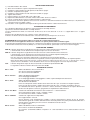
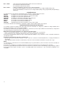
L8542301
Rev. 10/07/02
CENTRALE DI COMANDO
CONTROL UNIT
STEUEREINHEIT
CENTRALE DE COMMANDE
CENTRAL DE MANDO
CENTRALKA STEROWANIA
Logica24 RI
Libro istruzioni
Operating instructions
Betriebsanleitung
Livret d’instructions
Manual de instrucciones
Książeczka z instrukcjami
UNIONE NAZIONALE COSTRUTTORI
AUTOMATISMI PER CANCELLI, PORTE,
SERRANDE ED AFFINI
Dichiarazione CE di conformità
EC declaration of confirmity
Déclaration CE de conformité
Declaracion CE de conformidad
EG-Konformitatserklarung
Deklaracja UE o zgodności
Con la presente dichiariamo che il nostro prodotto
We hereby declare that our product
Hiermit erklaren wir, dass unser Produkt
Nous déclarons par la présente que notre produit
Por la presente declaramos que nuestro producto
Niniejszym oświadczamy że nasz produkt
LOGICA 24 RI
è conforme alle seguenti disposizioni pertinenti:
complies with the following relevant provisions:
folgenden einschlagigen Bestimmungen entspricht:
correspond aux dispositions pertinentes suivantes:
satisface las disposiciones pertinentes siguientes:
zgodny jest z poniżej wyszczególnionymi rozporządzeniami:
Direttiva sulla compatibilità elettromagnetica
(89/336/CCE, 93/68/CEE)
EMC guidelines (89/336/EEC, 93/68/EEC)
EMV-Richtlinie (89/336/EWG, 93/68/EWG)
Directive EMV (89/336/CCE, 93/68/CEE)
(Compatibilité électromagnétique)
Reglamento de compatibilidad electromagnética
(89/336/MCE, 93/68/MCE)
Wytyczna odnośnie zdolności współdziałania elektromagnetycznego (89/336/EWG, 93/68/EWG)
Benincà Luigi, Responsabile legale.
Sandrigo, 05/10/2005.
2
Direttiva sulla bassa tensione (73/23/CEE, 93/68/CEE)
Low voltage guidelines (73/23/EEC, 93/68/EEC)
Tiefe Spannung Richtlinie (73/23/EWG, 93/68/EWG)
Directive bas voltage (73/23/CEE, 93/68/CEE)
Reglamento de bajo Voltaje (73/23/MCE, 93/68/MCE)
Wytyczna odnośnie niskiego napięcia (73/23/EWG,
93/68/EWG)
Automatismi Benincà SpA
Via Capitello, 45
36066 Sandrigo (VI)
ITALIA
N1
L1
1
T1,6A
F2
2
0
0
18 VMOT
23
23
26
230
L1
VMOT
N1
24
0
F2,5A
ON
DL1
U2
PGM
J1 DAS
Close
DAS 8K2
CLS
OPN
TCA
RADIO
AMPC
J2
DAS
J1 DAS
Open
DAS N.C.
1
230Vac L
50Hz N
+
2
+ -
M1
-
M2
16
17
18
20
21
SCA
3W max
22
23
DAS
24
8k2
LAMP.
24Vdc
15
19
24Vac
1A max
ANT
F1
AMPO
PP
15
16
17
18
19
20
21
22
23
24
25
26
PHOT
SW2
STOP
SW1
3
4
5
6
7
8
9
10
11
12
13
14
SHIELD
25
ANT
26
Light
Service
+
3
-
4
5
M1
M2
6
7
SW1 (Open)
8
SW2 (Close)
9
STOP
10
PHOT
11
OPEN
12
CLOSE
13
P.P.
14
Centrale di comando Logica24 RI
La centrale elettronica Logica24 RI può essere utilizzata per il controllo di 1/2 motori con potenza non superiore a 120W+120W.
IMPORTANTE: Nel caso di utilizzo di due motori, collegare alla centrale di comando i finecorsa di un solo motore.
AVVERTENZE GENERALI
a) L’installazione elettrica e la logica di funzionamento devono essere in accordo con le normative vigenti.
b) I conduttori alimentati con tensioni diverse, devono essere fisicamente separati, oppure devono essere adeguatamente isolati
con isolamento supplementare di almeno 1 mm.
c) I conduttori devono essere vincolati da un fissaggio supplementare in prossimità dei morsetti.
d) Ricontrollare tutti i collegamenti fatti prima di dare tensione.
e) Controllare che le impostazioni dei Dip-Switch siano quelle volute.
f) Gli ingressi N.C. non utilizzati devono essere ponticellati.
FUNZIONI INGRESSI/USCITE
Centrale Logica24 RI
N° Morsetti
Funzione
Descrizione
1-2
Alimentazione
Ingresso 230Vac 50Hz (1-Fase/2-Neutro)
3-4
Lampeggiante
Collegamento lampeggiante 24Vac 40W max.
5-6
Luce Motore 2
Collegamento alla luce di cortesia del motore 2
(solo nel caso di utilizzo di 2 motori)
7
COM
Comune per finecorsa e tutti gli ingressi di comando.
8
SWO
Ingresso finecorsa APRE (contatto N.C.)
9
SWC
Ingresso finecorsa CHIUDE (contatto N.C.)
10
STOP
Ingresso pulsante STOP (contatto N.C.)
11
PHOT
Ingresso collegamento dispositivi di sicurezza, contatto N.C.
(ad es. fotocellule)
12
OPEN
Ingresso pulsante APRE (contatto N.O.)
13
CLOSE
Ingresso pulsante CHIUDE (contatto N.O.)
14
Passo-Passo
Ingresso pulsante passo-passo (contatto N.O.)
15-16
Motore1
Collegamento al motore 1 (15+/16-)
17-18
Motore 2
Collegamento al motore 2 (15+/16-)
da utilizzare solo nel caso di utilizzo di 2 motori
19-20
24 Vac
Uscita alimentazione accessori 24Vac/1A max.
ATTENZIONE: Nel caso di installazione della scheda caricabatteria CB.24V, l’uscita (in
assenza di alimentazione di rete) presenta una tensione 24Vdc - polarizzata.
Verificare il corretto collegamento dei dispositivi (19:+24Vdc - 20:-24Vdc).
21-22
SCA
Contatto pulito N.O. per spia cancello aperto.
23-24
COSTA
Ingresso contatto costa sensibile
Costa resistiva: Jumper “DAS” chiuso
Costa meccanica: Jumper “DAS” aperto
L’intervento della costa durante la fase di apertura arresta il movimento dell’anta.
Durante la fase di chiusura arresta il movimento, inverte (apre) per 3s.
25-26
Antenna
Collegamento antenna scheda radioricevente ad innesto (25-schermo/26-segnale).
0-24-VMOT
Secondario
Collegamento avvolgimento secondario trasformatore
L1-N1
Primario
Collegamento avvolgimento primario trasformatore
J2
Ricevitore Radio
Ricevente radio incorporata
NOTE:
a) Se presenti, i pulsanti a bordo del motore sono collegati ai comandi Passo/Passo e STOP.
Eventuali ulteriori sicurezze devono essere collegate in serie al comando STOP.
b) La luce di cortesia resta accesa per circa 90s ad ogni manovra.
c) La COSTA deve essere collegata esclusivamente agli appositi ingressi. Si possono utilizzare due tipi di COSTA:
Se si utilizza una costa con resistenza 8K2 chiudere il Jumper “DAS”.
Se si utilizza una costa meccanica con contatto N.C. aprire il Jumper “DAS”.
Se non si utilizza la costa ponticellare i morsetti 23-24, aprire il Jumper “DAS”.
4
REGOLAZIONE FINECORSA
1)
2)
3)
4)
5)
6)
7)
8)
9)
10)
Dare alimentazione alla centrale
Sbloccare manualmente e aprire completamente la porta.
Regolare la camma del finecorsa di apertura, il led SWO si spegne.
Chiudere completamente la porta.
Regolare la camma del finecorsa di chiusura, il led SWC si spegne.
Togliere alimentazione.
Portare la porta a circa metà della corsa e ribloccarla.
Ripristinare l’alimentazione. I led STOP, PHOT, SWO e SWC devono accendersi.
Dare un comando di passo-passo mediante pulsante o radiocomando.
La porta deve muoversi in apertura. Nel caso ciò non avvenisse, è sufficiente invertire tra loro i fili di marcia (15<>16) del motore
e gli ingressi finecorsa (SWO<>SWC).
11) Procedere con la regolazione dei Tempi e delle Logiche di funzionamento e della velocità motore.
ATTIVAZIONE RALLENTAMENTO
Se si desidera il rallentamento in apertura e chiusura portare in ON il Dip-Switch 3.
Impostare la velocità di rallentamento con il Dip-Switch 7.
La fase di rallentamento inizia con l’intervento dei finecorsa, ed ha una durata di 4” di cui 3” a coppia ridotta ed 1” a coppia
massima.
Durante la fase di rallentamento non è attivo il sensore amperomentrico.
Verificare che durante la fase di rallentamento in chiusura l’anta non percorra più di 5 cm di corsa.
REGOLAZIONE DELLA VELOCITÀ
ATTENZIONE! Questa regolazione influisce sul grado di sicurezza dell’automazione.
Verificare che la forza applicata sull’anta sia conforme con quanto previsto dalle normative vigenti.
Sul trasformatore di alimentazione è presente un connettore Faston (VMOT) che permette la regolazione della velocità dei motori su
3 diversi livelli. Posizionando il Faston (VMOT) su 15 si ha la velocità minore, spostandolo su 23 si ha la velocità maggiore.
FUNZIONE DEI TRIMMER
AMP-O Permette di regolare la soglia di intervento del sensore di corrente durante al fase di apertura.
L’intervento del sensore durante la fase di apertura provoca l’arresto del motore.
AMP-C Permette di regolare la soglia di intervento del sensore di corrente durante al fase di chiusura.
L’intervento del sensore durante la fase di chiusura provoca la completa riapertura della porta.
Viene immediatamanete effettuata una nuova manovra di chiusura.
Nel caso di un nuovo intervento amperometrico, l’operazione viene nuovamente ripetuta.
Se nessuna delle tre manovre di chiusura viene portata a termine la porta rimane in posizione di completa apertura.
Nota: All’inizio della manovra di chiusura, il motore funziona a coppia massima per circa 1.5”. In questa fase il sensore
amperometrico è disabilitato e rimane disabilitato finchè non viene disimpegnato il finecorsa di apertura SWO.
TCA
Permette di regolare il tempo di chiusura automatica. Verificare il Dip-Switch N°1= On.
La regolazione varia da un minimo di 1s ad un massimo di 90s
FUNZIONE DIP-SWITCH
DIP 1 “TCA”
Abilita o disabilita la chiusura automatica.
Off: chiusura automatica disabilitata
On: chiusura automatica abilitata
DIP 2 “Prelam.”
Abilita o disabilita il prelampeggio
Off: Prelampeggio disabilitato
On: Prelampeggio abilitato. Il lampeggiante si attiva 3s prima della partenza del motore.
DIP 3 “Rall.”
Abilita o disabilita il rallentamento.
Off: rallentamento disabilitato.
Il finecorsa di apertura “SWO” ritarda l’arresto del motore di 1s per consentire una migliore apertura
Il finecorsa di chiusura “SWC” ritarda l’arresto del motore di 1s per consentire una migliore chiusura
On: Rallentamento attivo in apertura e chiusura. L’arresto del motore è ritardato di 3s rispetto all’intervento
dei finecorsa di apertura e chiusura, per garantire il completamento della manovra.
DIP 4 “P.P. Mod”
Seleziona la modalità di funzionamento del ”Pulsante P.P.” e del trasmettitore.
Off: Funzionamento: APRE > STOP > CHIUDE > STOP >
On: Funzionamento: APRE > CHIUDE > APRE >
DIP 5 “COPPIA”
Seleziona la coppia massima disponibile.
Off: Coppia ridotta in chiusura.
Questa funzione rende maggiormente sensibile il sensore amperometrico durante la fase di chiusura,
aumentando il grado di sicurezza dell’automazione. Richiede pertanto una porta perfettamente bilanciata e
periodicamente controllata per non incorrere in anomali interventi del sensore.
On: Coppia a regime.
DIP 6 “Cond.”
Abilita o disabilita la funzione condominiale.
Off: Funzione condominiale disabilitata.
On: Funzione condominiale abilitata. L’impulso P.P. o del trasmettitore non ha effetto durante la fase di
apertura.
5
DIP 7 “VRall”
Selezione la velocità del motore durante la fase di rallentamento
Off: Velocità in rallentamento minima.
On: Velocità in rallentamento massima.
DIP 8 “Radio”
Abilita o disabilita i trasmettitori a codice programmabile
On: Ricevitore radio abilitato esclusivamente ai trasmettitori a codice variabile (rolling-code).
Off: Ricevitore abilitato a trasmettitori codice variabile (rolling-code) e programmabile (autoapprendimento e
dip/switch) .
DIAGNOSTICA LED
La centrale dispone di una serie di LED di autodiagnosi che consentono il controllo di tutte le funzioni:
Led SW1
Si spegne con l’attivazione del finecorsa di apertura SWO
Led SW2
Si spegne con l’attivazione del finecorsa di chiusura SWC
Led STOP
Si spegne con l’attivazione del pulsante STOP
Led PHOT
Si spegne con fotocellule non allineate o in presenza di ostacoli
Led OPN
Si accende con l’attivazione del pulsante OPEN
Led CLS
Si accende con l’attivazione del pulsante CLOSE
Led PP
Si accende con l’attivazione del pulsante PP
Led PGM
Lampeggia ad indicare il regolare funzionamento della centrale.
L’intervento della costa è segnalato da 5 lampeggi veloci del LED PGM seguiti da una pausa.
CONFIGURAZIONE RICEVITORE INCORPORATO
La centrale è dotata di un modulo radio incorporato per la ricezione di telecomandi sia a codice fisso che a codice variabile (vedi
funzioni dip-switch 8), con frequenza di 433.92MHz.
Per utilizzare un telecomando è prima necessario apprenderlo, la procedura di memorizzazione è illustrata di seguito, il dispositivo
è in grado di memorizzare fino a 64 codici diversi.
Memorizzazione di un nuovo trasmettitore con attivazione funzione P.P.
- Premere 1 volta il pulsante PGM per 1s, il LED DL1 inizia a lampeggiare con 1s di pausa.
- Premere entro 10s il pulsante del trasmettitore che si desidera memorizzare con funzione P.P.
Per uscire dalla programmazione, attendere 10s o premere il pulsante PGM per 1s, il LED DL1 riprende a lampeggiare normalmente
con pausa di 3s.
Cancellazione di tutti i trasmettitori dalla memoria
- Mantenere premuto il pulsante PGM per 15s, il LED DL1 inizia al lampeggiare velocemente e si spegne a cancellazione
avvenuta.
- Rilasciare il pulsante PGM, la memoria è stata cancella ed il LED DL1 riprende a lampeggiare normalmente con pausa di 3s.
NOTA:
I trasmettitori vengono memorizzati su un memoria EPROM (U2) che può essere rimossa e reinserita in una nuova centrale in caso
di sostituzione.
Per motivi di sicurezza, non è possibile memorizzare trasmettitori durante le fasi apertura/chiusura del motore.
Se entrando nella procedura di memorizzazione dei trasmettitori il LED DL1 emette un lampeggio lungo e si spegne, significa che la
memoria della ricevente è piena e non è possibile memorizzare altri trasmettitori o che il trasmettitore utilizzato non è compatibile.
6
Logica24 RI Control unit
The electronic control unit Logica24 RI can be used to control 1 or 2 motors with a power not exceeding 120W+120W.
IMPORTANT: Should two motors be used, connect the limit switches of one single motor to the control unit.
GENERAL WARNINGS
a)
b)
c)
d)
e)
f)
The wire connections and the operating logic should be in compliance with regulations in force.
The cables featuring different voltage should be detached, or adequately insulated by an additional insulation of at least 1 mm.
The cables should be further fastened in proximity to the terminals.
Check all connections before powering the unit.
Check that setting of the Dip-Switches are the required ones.
Normally Closed inputs which are not in use should be short-circuited 230VAC – keep to phase/neutral).
INPUT/OUTPUT FUNCTIONS
Logica24 RI Control Unit
Terminal
No.
Function
Description
1-2
Power supply
Input, 230VAC 50Hz (1-Phase/2-Neutral)
3-4
Flashing light
Connection of flashing light, 24Vac 40W max.
5-6
Light, Motor 2
Connection to the courtesy light of motor 2
(only when 2 motors are in use)
7
COM
Common for limit switch and all control inputs.
8
SWO
Input, OPEN limit switch (N.C. contact)
9
SWC
Input, CLOSE limit switch (N.C. contact)
10
STOP
Input, STOP push button (N.C. contact)
11
PHOT
Input, connection to safety devices, N.C. contact
(e.g. Photocells)
12
OPEN
Input, OPEN push button (N.O. contact)
13
CLOSE
Input, CLOSE push button (N.O. contact)
14
Step-by-Step
Input, step-by-step push button (N.O. contact)
15-16
Motor 1
Connection to motor 1 (15+/16-)
17-18
Motor 2
Connection to motor 2 (15+/16-)
To be used only when 2 motors are in use
19-20
24 Vac
Output, power supply of accessories, 24Vac/1A max.
IMPORTANT: If the battery charger board CB.24V is installed, the output (without mains
power connected) has a 24Vdc polarised voltage.
Make sure the devices are correctly connected (i.e. 19:+24Vdc - 20:-24Vdc).
21-22
SCA
Free contact, N.O. for open door warning light.
23-24
COSTA
Input, safety edge contact
Resistive edge: Closed “DAS” jumper
Mechanical edge: Open “DAS” jumper
If the safety edge is activated in the opening phase, the gate stops.
In the closing phase, the gate stops and the performs a movement reversion (opens) for
3s.
25-26
Aerial
Connection to the radio receiver card of the aerial (25-screen/26-signal).
0-24-VMOT
Secondary
Connection, winding of secondary transformer
L1-N1
Primary
Connection, winding of primary transformer
J2
Radio receiver
Bulit-in radio receiver.
REMARKS:
The courtesy light stays on for about 90s at each operation.
The safety EDGE should be connected only to the special inputs. Two types of EDGE can be used:
If a safety edge is used with 8K2 resistance, the “DAS” jumper should be closed.
If a mechanical safety edge with N.C. contact is used, the “DAS” Jumper should be opened.
If no edge is used, terminals 23-24 should be short-circuited , the “DAS” Jumper should be opened.
7
TO ADJUST THE LIMIT SWITCHES
1) Power the control unit
2) Manually release the system and completely open the door.
3) Adjust the opening limit switch cam, the SWO LED turns off.
4) Shut the door completely.
5) Adjust the closing limit switch cam, the SWC LED turns off.
6) Cut off power supply.
7) Move the door half-way and lock it again.
8) Reset power supply. The STOP, PHOT, SWO and SWC LED’s should light up.
9) Give a step-by-step control signal by pressing the appropriate button or using the remote control.
10) The door should move in the opening phase. In the negative, it is sufficient to invert the speed wires (15<>16) of the motor and
the limit switch inputs (SWO<>SWC).
11) Adjust Time, the Operating Logistics as well as the Motor speed.
ENABLING THE SLOWDOWN FEATURE
To enable the slowdown feature during opening and closing set Dip-Switch 3 to ON.
Preset the braking speed by using Dip-Switch 7.
The braking phase will start when the limit switches are triggered and will last for 4”, of which 3” at reduced torque and 1” at
maximum torque.
During the slowdown cycle the amperometric sensor is disabled. Make sure that, during the closing slowdown cycle the gate does
not travel more than 5 cm of the stroke.
TO ADJUST SPEED
WARNING! This adjustment affects the safety level of the automatic system.
Make sure that the force applied onto the gate wing complies with regulations in force.
The supply transformer is provided with a Faston (VMOT) connector which permits to adjust the motor speed at three different levels.
When the Faston (VMOT) is on 15, the speed is at minimum. When the Faston is moved to 23, the maximum speed is obtained.
FUNCTION OF TRIMMERS
AMP-O This trimmer allows to adjust the activation threshold of the current sensor in the opening phase.
When the sensor is triggered in the opening phase, the motor stops.
AMP-C This trimmer allows to adjust the activation threshold of the current sensor in the closing phase.
The sensor activation in the closing phase causes the total re-opening of the door. A new closing operation is then
immediately started.
In the event of a new amperometric activation, the operation is carried out again. If none of the three closure operations is
completed, the door will stay completely open.
N.B.: At the beginning of the closing operation, the motor operates at maximum torque for approx. 1.5”. In this phase the
amperometric sensor is disabled and remains disabled until the SWO opening limit switch is relased.
TCA
It allows to adjust the automatic closure time. Check Dip-Switch N°1= On.
The adjustment varies from 1s minimum to 90s maximum
DIP-SWITCH FUNCTIONS
DIP 1 “TCA”
The automatic closure is enabled or disabled
Off: disabled automatic closure
On: enabled automatic closure
DIP 2 “Prelam.”
Forewarning flashing light enabled or disabled
Off: disabled forewarning flashing light
On: enabled forewarning flashing light. The flashing light is activated 3 s before the starting of the motor.
DIP 3 “Braking”
Braking is enabled or disabled.
Off: disabled braking.
With the “SWO” opening limit switch, the motor stopping is delayed by 1 sec to allow a better opening.
With the “SWC” closing limit switch, the motor stopping is delayed by 1 sec to allow a better closing
On: Braking activated in the opening and closing phase. The motor stopping is delayed by 3 sec with respect
to the triggering of the opening and closing limit switches to allow the completion of the operation.
DIP 4 “P.P. Mod”
The operating mode of “P.P. Push button” and of the transmitter are selected.
Off: Operation: OPEN > STOP > CLOSE > STOP >
On: Operation : OPEN > CLOSE > OPEN >
DIP 5 “TORQUE”
The max torque available is selected with this Dip-Switch.
Off: Reduced torque in the closing phase.
This function increases the sensitiveness of the amperometric sensor during closure, thus increasing the
safety level of the system. Therefore, this function requires a perfectly balanced door, submitted to periodic
checking in order to avert any faulty triggering of the sensor.
On: Torque at regular operation.
DIP 6 “Cond.”
The multi-flat function is enabled or disabled.
Off: disabled multi-flat function.
On: enabled multi-flat function. The P.P. (Step-by-step) impulse or the impulse of the transmitter have no
effect in the opening phase.
8
DIP 7 “VRall”
Motor speed selection in the braking phase
Off: Minimum braking speed .
On: Maximum braking speed .
DIP 8 “Radio”
Enables or disables transmitters with programmable codes
On: Radio receiver enabled exclusively for rolling-code transmitters.
Off: Receiver enabled for both rolling-code and programmable transmitters (self-learn and dip-switch) .
LED DIAGNOSTICS
The control system has a series of self-diagnostics LED’s which allow to check all functions:
SW1 LED
It switches off when the SWO opening limit switch is triggered
SW2 LED
It switches off when the SWC closing limit switch is triggered
STOP LED
It switches off when the STOP push button is pressed
PHOT LED
It switches off when the photocells are not aligned or if obstacles are present
OPN LED
It switches on when the OPEN push button is pressed
CLS LED
It switches on when the CLOSE push button is pressed
PP LED
It switches on when the PP push button is pressed
PGM LED
It flashes to show the correct operation of the control unit.
5 quick flashes, followed by a pause, of LED PGM indicate the activation of the safety edge.
CONFIGURATION WITH BUILT-IN RECEIVER
The control unit is fitted with a built-in radio module for receiving remote controls both with fixed codes and variable codes (see
dip-switch 8 functions), with a frequency of 433.92MHz.
For a transmitter to be used, the module first has to self-learn its code. The memorise procedure is illustrated below, the module
can memorise up to 64 different codes.
Memorising a new transmitter by activating the P.P. function
- Press the PGM button once for 1sec and the DL1 LED will start blinking at 1 sec intervals.
- Press the transmitter button within 10 sec to memorise with the P.P. (Step-by-step) function
To exit the programming procedure wait 10 sec or press the PGM button for 1 sec, the DL1 LED will return to normal blinking at
3 sec intervals.
Cancelling all transmitters from the memory
- Keep the PGM button pressed for 15 sec, the DL1 LED will start blinking rapidly and when it goes out the memory has been
erased.
- Release the PGM button, the memory has been cancelled and the DL1 LED will return to normal blinking at 3 sec intervals.
N.B.:
The transmitters are stored on an EPROM (U2) memory board that can be removed and installed in a new control unit in case of
breakdown.
For safety reasons, transmitters cannot be memorised during the open/close cycles of the motor.
When entering the memorise transmitter procedure, if the DL1 LED gives a prolonged blink and then goes out, this signals that the
receiver memory is full and no other transmitters can be memorised or that the transmitter is not compatible.
9
Steuereinheit Logica24 RI
Die elektronische Zentrale Logica24 RI kann zur Steuerung von 1 bzw. 2 Motoren mit einer Leistung von maximal 120W+120W
verwendet werden.
WICHTIG: Wenn zwei Motoren installiert werden, nur die Endschalter eines einzigen Motors an die Steuereinheit
schließen.
ALLGEMEINE HINWEISE
a)
b)
c)
d)
e)
f)
Die elektrische Installation und die Betriebslogik müssen den geltenden Vorschriften entsprechen.
Die Leiter die mit unterschiedlichen Spannungen gespeist werden, müssen physisch getrennt oder sachgerecht mit einer
zusätzlichen Isolierung von mindestens 1 mm isoliert werden.
Die Leiter müssen in der Nähe der Klemmen zusätzlich befestigt werden.
Alle Anschlüsse nochmals prüfen, bevor die Zentrale mit Strom versorgt wird.
Kontrollieren, ob die Dip-Schalter richtig positioniert sind.
Die nicht verwendeten N.C. Eingänge müssen überbrückt werden.
FUNKTIONEN EINGÄNGE/AUSGÄNGE
Zentrale Logica24 RI
Klemme
Funktion
Beschreibung
1-2
Speisung
Eingang 230Vac 50Hz (1-Phase/2-Nulleiter)
3-4
Blinkleuchte
Ausgang Anschluss Blinkleuchte 24Vac 40W max.
5-6
Leuchte Motor 2
Anschluss an die Höflichkeitsleuchte des Motors 2
(nur wenn 2 Motoren installiert werden)
7
COM
Gemein für alle Steuerungseingänge.
8
SWO
Eingang Endschalter ÖFFNEN (Kontakt N.C.)
9
SWC
Eingang Endschalter SCHLIESSEN (Kontakt N.C.)
10
STOPP
Eingang STOPP-Taste (Kontakt N.C.)
11
PHOT
Eingang zum Anschluss von Sicherheitsvorrichtungen, Kontakt N.C. (z.B. Photozellen)
12
OPEN
Eingang Taste ÖFFNEN (Kontakt N.O.)
13
CLOSE
Eingang Taste SCHLIESSEN (Kontakt N.O.)
14
Schritt-Schritt
Eingang Taste Schritt-Schritt (Kontakt N.O.)
15-16
Motor 1
Anschluss an den Motor 1 (15+/16-)
17-18
Motor 2
Anschluss an den Motor 2 (15+/16-)
Nur im Falle der Verwendung von 2 Motoren
19-20
24 Vac
Ausgang Zubehörspeisung 24Vac/1A max.
ACHTUNG: Falls die Karte des Batterieladegeräts CB.24V installiert ist, weist der Ausgang (bei Ausfall der Netzversorgung) eine polarisierte Spannung von 24Vdc auf.
Den korrekten Anschluss der Vorrichtungen kontrollieren (19:+24Vdc - 20:-24Vdc).
21-22
SCA
Reiner Kontakt N.O. Für Meldeleuchte Tor offen
23-24
FLANKE
Eingang Kontakt Näherungsflanke
Widerstandsfähige Flanke: Jumper “DAS” geschlossen
Mechanische Flanke: Jumper “DAS” geöffnet
Wenn die Flanke beim Öffnen eingeschaltet wird, hält die Flügelbewegung an.
Beim Schließen wird die Bewegung angehalten und 3 sec. lang umgeschaltet (öffnen).
25-26
Antenne
Anschluss Antenne der Karte des steckbaren Funkempfängers und des eingebauten
Funkmoduls (25-Schirm/26-Signal).
0-24-VMOT
Sekundär
Anschluss Sekundärwicklung Trafo
L1-N1
Primär
Anschluss Primärwicklung Trafo
J2
Funkempfänger
Eingebauter Funkempfänger
BEMERKUNGEN:
Das Höflichkeitslicht bleibt bei jeder Bewegung circa 90s lang eingeschaltet.
Die FLANKE darf nur an die entsprechenden Eingänge geschlossen werden.
Es können zwei unterschiedliche FLANKENtypen verwendet werden:
Wenn eine Flanke mit einem Widerstand von 8K2 verwendet wird, den Jumper “DAS” schließen.
Wenn eine mechanische Flanke mit Kontakt N.C. verwendet wird, den Jumper “DAS” öffnen.
Wird keine Flanke verwendet, die Klemmen 23-24 überbrücken, den Jumper “DAS” öffnen.
10
EINSTELLUNG DER ENDSCHALTER
1)
2)
3)
4)
5)
6)
7)
8)
9)
10)
Die Zentrale mit Strom versorgen.
Von Hand entsichern und die Tür vollständig öffnen.
Den Nocken des Endschalters für das Öffnen einstellen; die Leuchte SWO erlischt.
Türe schließen.
Den Nocken des Endschalters für das Schließen einstellen, die Leuchte SWC erlischt.
Strom abtrennen.
Tür bis auf den halben Hub öffnen und wieder blockieren.
Wieder Strom geben. Die Leuchten STOPP, PHOT, SWO und SWC müssen aufleuchten.
Über die Taste oder die Fernbedienung einen Schritt-Schritt Befehl geben.
Die Tür muss sich öffnen. Sollte dies nicht der Fall sein, genügt es die Leiter (15<>16) für den Motorenbetrieb und die Eingänge
der Endschalter (SWO<>SWC) vertauschen.
11) Zeiten, Betriebslogik sowie Motorenleistung einstellen
AKTIVIERUNG DER VERLANGSAMUNG
Wenn beim Öffnen und beim Schließen eine Verlangsamung erwünscht ist, den Dip-Switch 3 auf ON stellen.
Die Geschwindigkeitsabnahme über den Dip-Schalter 7 einstellen.
Die Geschwindigkeitsabnahme beginnt wenn die Endschalter einschalten und dauert 4“ bei beschränktem und 1“ bei maximalem
Drehmoment.
Während der Verlangsamung ist der amperometrische Sensor nicht aktiv. Sicherstellen, dass der Torflügel während der
Verlangsamungsphase beim Schließen nicht mehr als 5 cm des Wegs zurücklegt.
GESCHWINDIGKEIT EINSTELLEN
ACHTUNG! Diese Einstellung hat Einfluss auf die Sicherheit der Automatik.
Die für das Tor angewendete Kraft muss den geltenden Vorschriften entsprechen.
Der Speisetrafo ist mit einem Faston Verbinder (VMOT) versehen, durch den die Motorengeschwindigkeit auf 3 verschiedene Stufen
eingestellt werden kann. Wird der Faston Verbinder (VMOT) auf 15 eingestellt, wird die Motorengeschwindigkeit auf das Minimum
geregelt; wird er auf 23 eingestellt, wird die maximale Motorengeschwindigkeit erreicht.
TRIMMER-FUNKTIONEN
AMP-O Ermöglicht es das Einschalten des Stromsensors während des Öffnens einzustellen.
Schaltet der Sensor beim Öffnen ein, so wird der Motor angehalten.
AMP-C Ermöglicht es das Einschalten des Stromsensors während des Schließens einzustellen.
Das Einschalten des Sensors während des Schließvorgangs führt zur vollständigen Öffnung der Tür.
Daraufhin folgt sofort ein neuer Schließvorgang.
Sollte der Stromsensor dann nochmals einschalten, wird der Vorgang wiederholt.
Falls keiner der drei Schließvorgänge zu Ende geführt wird, bleibt die Tür vollständig geöffnet.
Bemerkung: Am Anfang des Schließvorgangs, läuft der Motor bei maximalem Drehmoment etwa 1.5“ lang. In dieser Phase
ist der Stromsensor deaktiviert und bleibt solange deaktiviert bis der Öffnungsendschalter SWO nicht entsichert wird.
TCA
Ermöglicht es die Zeit des automatischen Schließvorgangs einzustellen. Kontrollieren ob Dip-Schalter Nr. 1= On.
Die Zeit kann zwischen 1 sec. und maximal 90 sec. eingestesllt werden.
DIP-SCHALTER-FUNKTIONEN
DIP 1 “TCA”
Aktiviert oder deaktiviert den automatischen Schließvorgang.
Off: automatischer Schließvorgang deaktiviert
On: automatischer Schließvorgang aktiviert
DIP 2 “Prelam.”
Aktiviert oder deaktiviert das Vorblinken.
Off: Vorblinken deaktiviert
On: Vorblinken aktiviert. Das Vorblinken beginnt 3 sec. vor dem Einschalten des Motors.
DIP 3 “Abn.”
Aktiviert oder deaktiviert die Geschwindigkeitsabnahme.
Off: Geschwindigkeitsabnahme deaktiviert.
Der Endschalter für das Öffnen “SWO” verzögert das Abstellen des Motors um 1s, um den Öffnungsvorgang
verbessern zu können
Der Endschalter für das Schließen “SWC” verzögert das Abstellen des Motors um 1s, um den Schließvorgang
verbessern zu können
On: Geschwindigkeitsabnahme beim Öffnen und Schließen aktiviert. Das Abstellen des Motors ist um 3s im
Verhältnis zu den Endschaltern Öffnen und Schließen verzögert, damit der Vorgang vervollständigt werden
kann.
DIP 4 “P.P. Mod”
Wählt die Betriebsweise der Taste P.P.“ und des Sendegeräts.
Off: Betrieb: ÖFFNEN > STOPP > SCHLIESSEN > STOPP >
On: Betrieb: ÖFFNEN > SCHLIESSEN > ÖFFNEN >
DIP 5 “DREHM.”
Wählt das maximal zulässige Drehmoment.
Off: Drehmoment beim Schließen beschränkt.
Mit dieser Funktion wird die Empfindlichkeit des Stromsensors beim Schließen erhöht so dass eine höhere
Sicherheit der Automation gewährleistet werden kann. Daher muss die Tür ganz genau ausgewuchtet sein
und periodisch kontrolliert werden, um Fehlerschaltungen am Sensor zu vermeiden.
On: Drehmoment bei Betrieb.
DIP 6 “Cond.”
Aktiviert oder deaktiviert die Funktion Wohngemeinschaft.
Off: Funktion Wohngemeinschaft deaktiviert.
On: Funktion Wohngemeinschaft aktiviert. Auf den Öffnungsvorgang haben weder der Schritt-Schritt-Impuls
11
noch der Impuls des Sendegeräts Einfluss.
DIP 7 “VRall”
Wahl der Motorengeschwindigkeit während der Geschwindigkeitsabnahme
Off: Mindeste Geschwindigkeitsabnahme.
On: Maximale Geschwindigkeitsabnahme.
DIP 8 “Radio”
Aktiviert oder deaktiviert die Sender mit programmierbarem Code
On: Funkempfänger ausschließlich für Sender mit variablem Code aktiviert (Rolling-Code).
Off: Empfänger für Sender mit variablem (Rolling-Code) und programmierbarem (Selbstlernung und DipSwitch) Code aktiviert.
DIAGNOSTIK DER LEUCHTEN
Die Zentrale verfügt über eine Reihe von Leuchten zur Selbstdiagnostik über welche alle Funktionen kontrolliert werden können:
Led SW1
Schaltet aus, wenn der Endschalter SWO für das Öffnen aktiviert wird.
Led SW2
Schaltet aus, wenn der Endschalter SWC für das Schließen aktiviert wird.
Led STOP
Schaltet aus, wenn die STOPP Taste aktiviert wird
Led PHOT
Schaltet aus, wenn Fotozellen nicht gefluchtet sind oder Hindernisse vorhanden sind.
Led OPN
Schaltet ein, wenn die Taste OPEN aktiviert wird
Led CLS
Schaltet ein, wenn die Taste CLOSE aktiviert wird.
Led PP
Schaltet ein, wenn die Taste PP aktiviert wird.
Led PGM
Blinkt, was bedeutet dass die Zentrale ordentlich funktioniert.
Das Einschalten der Flanke wird durch ein schnelles, 5-maliges Blinken der LED PGM gefolgt von einer Pause gemeldet.
KONFIGURATION DES EINGEBAUTEN EMPFÄNGERS
Die Zentrale ist mit einem eingebauten Funkmodul für den Empfang von Fernbedienungen mit fixem oder variablem Code (siehe
Funktionen Dip-Switch 8), bei einer Frequenz von 433.92MHz ausgestattet.
Um eine Fernbedienung benutzen zu können, muss diese zunächst programmiert werden. Das Speicherverfahren wird nachstehend
beschrieben. Die Vorrichtung kann bis zu 64 verschiedene Codes speichern.
Speichern eines neuen Senders mit Aktivierung der Funktion P.P. (Schrittschaltung)
- 1 Mal die Taste PGM 1s lang drücken, die LED für DL1 beginnt mit Abständen von 1s zu blinken.
- Innerhalb von 10s die Taste des Senders drücken, die mit der Funktion P.P. belegt werden soll.
Um den Programmierungsmodus zu verlassen, 10s abwarten oder die Taste PGM 1s lang drücken, die LED für DL1 blinkt erneut normal
mit Abständen von 3s.
Löschen aller Sender aus dem Speicher
- Die Taste PGM 15s lang gedrückt halten, die LED für DL1 beginnt schnell zu blinken und geht nach abgeschlossenem Löschen aus.
- Nun die Taste PGM loslassen; der Speicher wurde gelöscht und die LED für DL1 blinkt wieder normal mit Abständen von 3s.
NB:
Die Sender werden in einem EPROM-Speicher (U2) gespeichert, der ausgebaut und gegebenenfalls in eine neue Zentrale eingebaut
werden kann. Aus Sicherheitsgründen können die Sender nicht während des Öffnens/Schließens des Motors gespeichert werden.
Wenn nach Zugriff auf das Speicherverfahren der Sender die LED für DL1 lange blinkt und dann ausgeht, bedeutet dies, dass der
Speicher des Senders voll ist und keine weiteren Sender eingespeichert werden können, oder dass der Sender nicht kompatibel ist.
12
Centrale de commande Logica24 RI
La centrale électronique Logica24 RI peut être utilisée pour le contrôle de 1 ou 2 moteurs ayant une puissance ne dépassant pas
les 120W+120W.
IMPORTANT: En cas d’utilisation de deux moteurs, connecter à la centrale de commande les fins de course d’un seul
moteur
AVERTISSEMENTS GENERAUX
a) L’installation électrique et la logique de fonctionnement doivent être conformes aux normes en vigueur.
b) Les conducteurs alimentés avec des tensions différentes doivent être séparés physiquement, ou adéquatement isolés avec une
isolation supplémentaire d’au moins 1 mm.
c) Les conducteurs doivent être contraints par une fixation supplémentaire à proximité des bornes.
d) Avant de mettre sous tension, contrôler à nouveau toutes les connexions réalisées.
e) Contrôler que les réglages des dip-switches sont ceux désirés.
f) Réaliser un pontet sur les entrées N.F. non utilisées.
FONCTIONS ENTREES/SORTIES
Centrale Logica24 RI
N. Bornes
Fonction
Description
1-2
Alimentation
Entrée 230Vac 50Hz (1-Phase/2-Neutre)
3-4
Clignotant
Connexion clignotant 24Vac 40W max.
5-6
Lumière Moteur 2
Connexion à la lumière de courtoisie du moteur 2
(seulement en cas d’utilisation de 2 moteurs)
7
COM
Commun pour fins de course et toutes les entrées de commande.
8
SWO
Entrée fin de course OUVRIR (contact N.F.)
9
SWC
Entrée fin de course FERMER (contact N.F.)
10
STOP
Entrée bouton STOP (contact N.F.)
11
PHOT
Entrée connexion dispositifs de sécurité, contact N.F.
(par ex. photocellules)
12
OPEN
Entrée bouton OUVRIR (contact N.O.)
13
CLOSE
Entrée bouton FERMER (contact N.O.)
14
Pas à pas
Entrée bouton pas à pas (contact N.O.)
15-16
Moteur 1
Connexion au moteur 1 (15+/16-)
17-18
Moteur 2
Connexion au moteur 2 (15+/16-)
S’emploie seulement en cas d’utilisation de 2 moteurs
19-20
24 Vac
Sortie alimentation accessoires 24Vac/1A max.
ATTENTION: En cas d’installation de la carte chargeur de batterie CB.24V, la sortie (en
l’absence d’alimentation de secteur) présente une tension de 24 Vcc - polarisée.
Vérifier la connexion correcte des dispositifs (19:+24 Vcc - 20:-24 Vcc).
21-22
SCA
Contact libre N.O. pour voyant portail ouvert.
23-24
Bourrelet
Entrée contact bourrelet sensible
Bourrelet résistif: Jumper “DAS” fermé
Bourrelet mécanique: Jumper “DAS” ouvert
L’intervention du bourrelet durant l’ouverture arrête le mouvement de la porte.
Durant la fermeture il arrête le mouvement et l’inverse (ouvre) pendant 3s.
25-26
Antenne
Connexion antenne carte récepteur radio à enclenchement (25- écran/26-signal).
0-24-VMOT
Secondaire
Connexion enroulement secondaire transformateur
L1-N1
Primaire
Connexion enroulement primaire transformateur
J2
Récepteur radio
Récepteur radio incorporé
NOTE
A chaque manœuvre, la lumière de courtoisie demeure allumée pendant environ 90s.
Le BOURRELET doit être exclusivement connecté aux entrées prévues. Deux types de bourrelets peuvent être utilisés:
Si on utilise un bourrelet avec une résistance 8K2, fermer le Jumper “DAS”.
Si on utilise un bourrelet mécanique avec un contact N.F. ouvrir le Jumper “DAS”.
Si on n’utilise pas de bourrelet, réaliser un pontet aux bornes 23-24, ouvrir le Jumper “DAS”.
13
RÉGLAGE DES FINS DE COURSE
1)
2)
3)
4)
5)
6)
7)
8)
9)
10)
Alimenter la centrale
Déverrouiller manuellement et ouvrir complètement la porte.
Régler la came du fin de course d’ouverture, la led SWO s’éteint.
Fermer complètement la porte.
Régler la came du fin de course de fermeture, la led SWC s’éteint.
Couper l’alimentation.
Amener la porte à environ la moitié de sa course et la rebloquer.
Restaurer l’alimentation. Les leds STOP, PHOT, SWO et SWC doivent s’éclairer.
Donner une commande pas à pas en intervenant sur le bouton ou sur la radiocommande.
La porte doit se déplacer en ouverture. Si cela n’a pas lieu, il suffira d’inverser entre eux les fils de marche (15<>16) du moteur
et les entrées des fins de course (SWO<>SWC).
11) Régler les temps et les logiques de fonctionnement, ainsi que la vitesse du moteur.
ACTIVATION RALENTISSEMENT
Si l’on désire le ralentissement en ouverture et fermeture, mettre sur ON le Dip-Switch 3.
Saisissez la vitesse de ralentissement avec le Dip-Switch 7.
La phase de ralentissement commence avec l’intervention des fins de course, pour une durée de 4” dont 3” à couple réduit et 1” à
couple maximum.
Durant la phase de ralentissement, le capteur ampèremétrique n’est pas actif. Vérifier que durant la phase de ralentissement en
fermeture le vantail n’effectue pas plus de 5 cm de course.
RÉGLAGE DE LA VITESSE
ATTENTION! Ce réglage influe sur le degré de sécurité de l’automation.
Vérifier que la force appliquée sur la porte est conforme aux préconisations des normes en vigueur.
Le transformateur d’alimentation monte un connecteur Faston (VMOT) permettant de régler la vitesse des moteurs sur 3 niveaux
différents. Placer le Faston (VMOT) sur 15 pour obtenir la plus petite vitesse, et sur 23 pour obtenir la vitesse maximum.
FONCTION DES TRIMMERS
AMP-O Permet de régler le seuil d’intervention du capteur de courant durant l’ouverture.
L’intervention du capteur durant l’ouverture provoque l’arrêt du moteur.
AMP-C Permet de régler le seuil d’intervention du capteur de courant durant la fermeture.
L’intervention du senseur durant la phase de fermeture provoque la réouverture complète de la porte.
Une nouvelle manœuvre de fermeture est immédiatement mise en œuvre.
Dans le cas d’une nouvelle intervention ampérométrique, l’opération est répétée à nouveau.
Si aucune des trois manoeuvres de fermeture est accomplie, la porte reste en position d’ouverture complète.
Note: Au début de la manoeuvre de fermeture, le moteur fonctionne à couple maximum pendant 1.5” environ. Dans cette
phase le senseur ampérométrique est invalidé et il demeure invalidé jusqu’à ce que le fin de course d’ouverture SWO ne
soit désengagé.
TCA
Permet de régler le temps de fermeture automatique. Vérifier le Dip-Switch N°1= On.
Le réglage varie d’un minimum de 1 s à un maximum de 90s
FONCTION DIP-SWITCH
DIP 1 “TCA”
Valide ou invalide la fermeture automatique.
Off: fermeture automatique invalidée
On: fermeture automatique validée
DIP 2 “Pré-clign.”
Valide ou invalide le clignotement
Off: Clignotement invalidé
On: Clignotement validé. Le clignotement s’active 3s avant le démarrage du moteur.
DIP 3 “Rall.”
Valide ou invalide le ralentissement.
Off: ralentissement invalidé.
Le fin de course d’ouverture “SWO” retarde l’arrêt du moteur d’une 1s pour permettre une ouverture
meilleure. Le fin de course de fermeture “SWC” retarde l’arrêt du moteur d’une 1s pour permettre une
fermeture meilleure.
On: Ralentissement actif en phase d’ouverture et de fermeture. L’arrêt du moteur est retardé de 3s par rapport
à l’intervention des fins de course d’ouverture et de fermeture, pour garantir l’achèvement de la manoeuvre.
DIP 4 “P.P. Mod”
Sélectionne le mode de fonctionnement du ”Bouton P.P.” et de l’émetteur.
Off: Fonctionnement: OUVRIR > STOP > FERMER > STOP >
On: Fonctionnement: OUVRIR > FERMER > OUVRIR >
DIP 5 “COUPLE”
Sélectionnez le couple maximum disponible.
Off: Couple réduit en phase de fermeture.
Cette fonction augmente la sensibilité du senseur ampérométrique durant la phase de fermeture, en
augmentant ainsi le degré de sécurité de l’automation. Par conséquent la porte doit être parfaitement
balancée et périodiquement contrôlée pour ne pas risquer des interventions anomales du senseur.
On: Couple à régime.
DIP 6 “Cond.”
Valide ou invalide la fonction copropriété.
Off: Fonction copropriété invalidée.
On: Fonction copropriété validée. L’impulsion P.P. ou de l’émetteur n’a aucun effet durant l’ouverture.
14
DIP 7 “VRall”
Sélection de la vitesse du moteur durant le ralentissement
Off: Vitesse en ralentissement minimum.
On: Vitesse en ralentissement maximum.
DIP 8 “Radio”
Active ou désactive les émetteurs à code programmable
On : Récepteur radio compatible exclusivement avec les émetteurs à code variable (rolling-code).
Off : Récepteur radio compatible avec les émetteurs à code variable (rolling-code) et programmable
(auto-apprentissage et dip-switch).
DIAGNOSTIC LEDS
La centrale dispose d’une série de leds d’autodiagnostic qui permettent le contrôle de toutes les fonctions.
Led SW1
Elle s’éteint lorsque le fin de course d’ouverture SWO s’active.
Led SW2
Elle s’éteint lorsque le fin de course de fermeture SWC s’active.
Led STOP
Elle s’éteint lorsqu’on intervient sur le bouton STOP
Led PHOT
Elle s’éteint lorsque les photocellules ne sont pas alignées ou en présence d’obstacles
Led OPN
Elle s’éclaire lorsqu’on intervient sur le bouton OPEN
Led CLS
Elle s’éclaire lorsqu’on intervient sur le bouton CLOSE
Led PP
Elle s’éclaire lorsqu’on intervient sur le bouton PP
Led PGM
Elle clignote pour indiquer que la centrale fonctionne régulièrement.
L’intervention de la barre est indiquée par 5 clignotements rapides du LED PGM suivis par une pause.
CONFIGURATION RÉCEPTEUR INCORPORÉ
La logique de commande est munie d’un module radio incorporé pour la réception d’émetteurs aussi bien à code fixe qu’à code
variable (voir fonctions dip-switch 8), à la fréquence de 433,92 MHz.
Pour utiliser un émetteur, il faut d’abord l’enregistrer, la procédure de mémorisation est illustrée ci-après, le dispositif est en mesure
de mémoriser jusqu’à 64 codes différents.
Mémorisation d’un nouvel émetteur avec activation fonction P.P.
- Presser 1 fois la touche PGM pendant 1 s, la LED DL1 commence à clignoter avec 1 s de pause.
- Presser dans les 10 s la touche de l’émetteur que l’on souhaite mémoriser avec fonction P.P.
Pour sortir de la programmation, attendre 10 s ou presser la touche PGM pendant 1 s, la LED DL1 recommence à clignoter
normalement avec une pause de 3 s.
Effacement de tous les émetteurs de la mémoire
- Maintenir la touche PGM enfoncée pendant 15 s, la LED DL1 commence à clignoter rapidement et s’éteint quand l’effacement a
eu lieu.
- Relâcher la touche PGM, la mémoire a été effacée et la LED DL1 recommence à clignoter normalement avec une pause de 3 s.
N.B.:
Les émetteurs sont mémorisés dans une mémoire EPROM (U2) qui peut être enlevée et remise dans une nouvelle logique de
commande en cas de remplacement.
Pour des raisons de sécurité, il n’est pas possible de mémoriser des émetteurs durant les phases d’ouverture et de fermeture.
Si la LED DL1 émet un long clignotement puis s’éteint quand on entre dans la procédure de mémorisation, cela signifie que
la mémoire du récepteur est pleine et qu’il n’est pas possible de mémoriser d’autres émetteurs ou que l’émetteur n’est pas
compatible.
15
Central de control Logica24 RI
La central electrónica Logica24 RI se puede utilizar para controlar 1/2 motores con potencia no mayor que 120W+120W.
IMPORTANTE: Si se utilizan dos motores, conectar con la central de control los final de carrera de un solo motor.
ADVERTENCIAS GENERALES
a) La instalación eléctrica y la lógica de funcionamiento deben cumplir las normas vigentes.
b) Los conductores alimentados con tensiones distintas deben estar físicamente separados, o bien deben estar adecuadamente
aislados con aislamiento suplementario de por lo menos 1 mm.
c) Los conductores deben estar vinculados por una fijación suplementaria cerca de los bornes.
d) Comprobar todas las conexiones efectuadas antes de dar la tensión.
e) Comprobar que las configuraciones de los Dip-Switch sean las deseadas.
f) Las entradas N.C. no utilizadas deben estar puenteadas.
FUNCIONES ENTRADAS/SALIDAS
Central Logica24 RI
N° Bornes
Función
Descripción
1-2
Alimentación
Entrada 230Vac 50Hz (1-Fase/2-Neutro)
3-4
Intermitente
Conexión intermitente 24VCA 40W máx.
5-6
Luz Motor 2
Conexión con la luz de cortesía del motor 2
(sólo si se usan 2 motores)
7
COM
Común para final de carrera y todas las entradas de control.
8
SWO
Entrada final de carrera ABRE (contacto N.C.)
9
SWC
Entrada final de carrera CIERRA (contacto N.C.)
10
STOP
Entrada botón STOP (contacto N.C.)
11
PHOT
Entrada conexión dispositivos de seguridad, contacto N.C.
(por ej. fotocélulas)
12
OPEN
Entrada botón ABRE (contacto N.A.)
13
CLOSE
Entrada botón CIERRA (contacto N.A.)
14
Paso-Paso
Entrada botón paso-paso (contacto N.A.)
15-16
Motor 1
Conexión con el motor 1 (15+/16-)
17-18
Motor 2
Conexión con el motor 2 (15+/16-) a utilizar sólo si se utilizan 2 motores
19-20
24 Vac
Salida alimentación accesorios 24Vac/1A máx.
ATENCIÓN: De estar instalada la tarjeta carga-baterías CB.24V, la tensión de la salida (sin
alimentación de red) es de 24Vdc - polarizada.
Verificar que los dispositivos (19:+24Vdc - 20:-24Vdc) estén conectados correctamente.
21-22
SCA
Contacto limpio N.A. para chivato cancela abierta.
23-24
BORDE
Entrada contacto borde sensible
Borde resistivo: Puente “DAS” cerrado
Borde mecánico: Puente “DAS” abierto
La actuación del borde durante la fase de apertura detiene el movimiento de la puerta.
Durante la fase de cierre detiene el movimiento, invierte (abre) por 3s.
25-26
Antena
Conexión antena tarjeta radioreceptora de enchufe (23-pantalla/24-señal).
0-24-VMOT
Secundario
Conexión bobinado secundario transformador
L1-N1
Primario
Conexión bobinado primario transformador
J2
Receptor Radio
Radiorreceptor incorporado.
NOTAS
La luz de cortesía queda encendida durante aproximadamente 90s a cada maniobra.
El BORDE debe estar conectado exclusivamente con sus correspondientes entradas.
Se pueden utilizar dos tipos de BORDE (Costa):
Si se utiliza un borde con resistencia 8K2 cerrar el Puente “DAS”.
Si se utiliza un borde mecánico con contacto N.C. abrir el Puente “DAS”.
Si no se utiliza el borde puentear los bornes 23-24.
16
REGULACIÓN FINAL DE CARRERA
1)
2)
3)
4)
5)
6)
7)
8)
9)
10)
Dar alimentación a la central
Desbloquear manualmente y abrir completamente la puerta.
Ajustar la excéntrica del final de carrera de apertura, el LED SWO se apaga.
Cerrar completamente la puerta.
Ajustar la excéntrica del final de carrera de cierre, el LED SWC se apaga.
Cortar la alimentación.
Llevar la puerta a aproximadamente mitad de la carrera y boquearla de nuevo.
Restablecer la alimentación. Los LEDs STOP, PHOT, SWO y SWC deben encenderse.
Dar un comando de paso-paso con botón o mando a distancia.
La puerta debe moverse en apertura. En caso contrario basta invertir entre ellos los hilos de marcha (15<>16) del motor y las
entradas final de carrera (SWO<>SWC).
11) Proceder con la regulación de los Tiempos y de las Lógicas de funcionamiento y de la velocidad motor.
ACTIVACIÓN DE LA DECELERACIÓN
Para obtener la deceleración en apertura y cierre, poner el Dip-Switch 3 en On.
Configurar la velocidad de ralentización a través del Dip-Switch 7.
La fase de ralentización comienza con la actuación de los final de carrera y tiene una duración de 4 segundos, 3 de los cuales con
par reducido y 1 segundo con par máximo.
Durante la fase de deceleración no está activado el sensor amperimétrico. Verificar que la cancela en la fase de deceleración al
cerrar no recorra más de 5 cm de carrera.
REGULACIÓN DE LA VELOCIDAD
¡ATENCIÓN! Esta regulación repercute en el grado de seguridad de la automatización.
Comprobar que la fuerza aplicada sobre la hoja sea conforme con cuanto previsto por las normas vigentes.
En el transformador de alimentación hay presente un conector Faston (VMOT) que permite la regulación de la velocidad de los
motores en 3 niveles distintos. Poniendo el Faston (VMOT) en 15 se tiene la velocidad más lenta, desplazándolo en 23 se tiene la
mayor velocidad.
FUNCIÓN DE LOS TRIMMER
AMP-O Permite ajustar el umbral de actuación del sensor de corriente durante al fase de apertura.
La actuación del sensor durante la fase de apertura provoca la parada del motor.
AMP-C Permite ajustar el umbral de actuación del sensor de corriente durante al fase de cierre.
La actuación del sensor durante la fase de cierre provoca la completa re-apertura de la puerta.
Es efectuada inmediatamente una nueva maniobra de cierre.
En el caso de una nueva actuación amperimétrica, la operación es repetida de nuevo.
Si ninguna de las tres maniobras de cierre es llevada a término, la puerta queda en posición de completa apertura.
Nota: Al comienzo de la maniobra de cierre, el motor funciona con par máximo durante aproximadamente 1.5”. En esta fase
el sensor amperimétrico está inhabilitado y queda inhabilitado hasta que se libra el final de carrera de apertura SWO.
TCA
Permite ajustar el tiempo de cierre automático. Comprobar el Dip-Switch N°1= On.
La regulación varía entre un mínimo de 1s y un máximo de 90s
FUNCIÓN DIP-SWITCH
DIP 1 “TCA”
Habilita o inhabilita el cierre automático.
Off: cierre automático inhabilitado
On: cierre automático habilitado
DIP 2 “Prelam.”
Habilita o inhabilita la pre-intermitencia.
Off: Intermitencia previa inhabilitada
On: Intermitencia previa habilitada. El intermitente se activa 3s antes del arranque del motor.
DIP 3 “Ral.”
Habilita o inhabilita la ralentización.
Off: ralentización inhabilitada.
El final de carrera de apertura “SWO” retrasa la parada del motor 1segundo para consentir una mejor
apertura. El final de carrera de cierre “SWC” retrasa la parada del motor 1segundo para consentir un mejor
cierre
On: Ralentización activa en apertura y cierre. La parada del motor está retrasada 3 segundos con respecto a
la actuación de los final de carrera de apertura y cierre, para garantizar que se termine la maniobra.
DIP 4 “P.P. Mod”
Selecciona la modalidad de funcionamiento del ”Botón P.P.” y del transmisor.
Off: Funcionamiento: ABRE > STOP > CIERRA > STOP >
On: Funcionamiento: ABRE > CIERRA > ABRE >
DIP 5 “PAR”
Selecciona el par máximo disponible.
Off: Par reducido en cierre.
Esta función hace más sensible el sensor amperimétrico durante la fase de cierre, aumentando el grado de
seguridad de la automatización. Requiere por lo tanto una puerta perfectamente balanceada y periódicamente
controlada para no tener actuaciones anómalas del sensor.
On: Par a régimen.
DIP 6 “Com.”
Habilita o inhabilita la función comunidad.
Off: Función comunidad inhabilitada.
On: Función comunidad habilitada. El impulso P.P. o del transmisor no tiene efecto durante la fase de
apertura.
17
DIP 7 “VRall”
Selección de la velocidad del motor durante la fase de ralentización
Off: Velocidad en ralentización mínima.
On: Velocidad en ralentización máxima.
DIP 8 “Radio”
Habilita o deshabilita los transmisores de código programable
On: Radiorreceptor habilitado exclusivamente con transmisores de código variable (rolling-code).
Off: Receptor habilitado con transmisores de código variable (rolling-code) y programable (autoaprendizaje y
dip/switch) .
DIAGNÓSTICO LED
La central tiene una serie de LEDs de autodiagnosis que permiten controlar todas las funciones:
LED SW1
Se apagar con la activación del final de carrera de apertura SWO
LED SW2
Se apagar con la activación del final de carrera de cierre SWC
LED STOP
Se apagar con la activación del botón STOP
LED PHOT
Se apaga con fotocélulas no alineadas o ante obstáculos
LED OPN
Se enciende con la activación del botón OPEN
LED CLS
Se enciende con la activación del botón CLOSE
LED PP
Se enciende con la activación del botón PP
LED PGM
Parpadea para indicar el funcionamiento correcto de la central.
La actuación del borde está señalada por 5 parpadeos rápidos del LED PGM seguidos de una pausa.
CONFIGURACIÓN DEL RECEPTOR INCORPORADO
La centralita incorpora un módulo radio para recibir desde los telemandos el código fijo y también el código variable (véase
funciones dip-switch 8), con frecuencia de 433.92MHz.
Para utilizar un telemando hay que aprenderlo primero; a continuación se indica el procedimiento de memorización, el dispositivo
está capacitado para memorizar hasta 64 códigos diversos.
Memorización de un nuevo transmisor con activación de la función P.P.
- Pulsar 1 vez el pulsador PGM por 1 seg., el LED DL1 comienza a destellar con 1 seg. de pausa.
- Pulsar dentro de 10 segs. el pulsador del transmisor que se desea memorizar con función P.P.
Para salir de la programación esperar 10 segs. o pulsar el pulsador PGM por 1 seg., el LED DL1 vuelve a destellar normalmente
con pausa de 3 segs.
Cancelación de la memoria de todos los transmisores
- Mantener presionado el pulsador PGM por 15 segs, el LED DL1 comienza a destellar rápidamente y se apaga al realizarse la
cancelación.
- Soltar el pulsador PGM, la memoria se ha borrado y el LED DL1 vuelve a destellar normalmente con pausa de 3 segs.
NOTA:
Los transmisores se memorizan en una memoria EPROM (U2) que se puede eliminar y volver a insertar en una nueva centralita, en
caso de sustitución.
Por razones de seguridad, no es posible memorizar los transmisores durante las fases de apertura/cierre del motor.
Si al entrar en el procedimiento de memorización de los transmisores el LED DL1 emite un destello largo y luego se apaga, significa
que la memoria del receptor está llena y que no es posible guardar otros transmisores, o que el transmisor empleado no es
compatible.
18
Centralka sterowania Logica24 RI
Elektroniczna centralka Logica24 RI może być stosowana do sterowania 1-2 silnikami o mocy nie większej jak 120W+120W.
UWAGA: W przypadku zainstalowania dwu silników należy podłączyć do centralki sterowania wyłącznik krańcowy tylko
jednego sinika.
OSTRZEŻENIA OGÓLNE
a) Instalacja elektryczna oraz system działania urządzenia muszą być zgodne z obowiązującymi normami.
b) Przewody zasilane różnego rodzaju napięciem muszą być oddzielone od siebie lub odpowiednio izolowane z zastosowaniem
dodatkowej izolacji o grubości co najmniej 1 mm.
c) W pobliżu zacisków przewody muszą być przymocowane dodatkowym umocowaniem.
d) Przed włączeniem zasilania należy ponownie sprawdzić wszystkie podłączenia.
e) Sprawdzić czy wszystkie ustawienia Dip-Switchów są takie, jak zamierzone.
f) Nie używane wejścia N.C. normalnie zwarte należy zmostkować.
WEJŚCIA/WYJŚCIA
Centralka Logica24 RI
N° Zacisku
Funkcja
Opis
1-2
Zasilanie
Wejście 230Vac 50Hz (1-Faza/2-Zerowy)
3-4
Lampa migocąca
Podłączenie lampy migocą cej 24Vac 40W max.
5-6
Oświetlenie silnika 2
Podłączenie oświetlenia silnika 2
(tylko w przypadku zastosowania 2 silników)
7
WSP
Wspólny dla krańcowego ogranicznika biegu i wszystkich wejść sterowania
8
SWO
Wejście krańcowego ogranicznika biegu OTWIERANIA (zestyk N.C. normalnie
zwarty)
9
SWC
Wejście krańcowego ogranicznika biegu ZAMYKANIA (zestyk N.C. normalnie zwarty)
10
STOP
Wejście przycisku STOP (zestyk N.C. normalnie zwarty)
11
PHOT
Wejście podłączenia urządzeń bezpieczeństwa, zestyk N.C. normalnie zwarty
(n.p. fotokomórki)
12
OPEN
Wejście przycisku OTWIERA (zestyk N.O. NORMALNIE OTWARTY)
13
CLOSE
Wejście przycisku ZAMYKA (zestyk N.O. normalnie otwarty)
14
Posuw-Posuw
Wejście przycisku Posuw-Posuw (zestyk N.O. normalnie otwarty)
15-16
Silnik1
Połączenie silnika 1 (15+/16-)
17-18
Silnik 2
Połączenie silnika 2 (15+/16-)
Stosować tylko w przypadku używania 2 silników
19-20
24 Vac
Wyjście zasilania akcesoriów 24Vac/1A max.
UWAGA: W przypadku instalacji karty przekaźnika prądu baterii CB.24V, wyjście (bez
napięcia sieciowego) wykazuje napięcie 24Vdc - spolaryzowane.
Sprawdzić podłączenie przyrządów (19:+24Vdc - 20:-24Vdc).
21-22
SCA
Zestyk wolny N.O. normalnie otwarty dla czujnika bramy otwartej.
23-24
KRAWĘDŹ
Wejście zestyku krawędzi bezpieczeństwa
Elektroniczna krawędź bezpieczeństwa: Jumper “DAS” zwarty
Mechaniczna krawędź bezpieczeństwa: Jumper “DAS” otwarty
Zadziałanie krawędzi bezpieczeństwa w fazie otwierania zatrzymuje ruch skrzydła.
Podczas fazy zamykania zatrzymuje ruch skrzydła, a następnie odwraca bieg
(otwiera) przez 3 sek.
25-26
Antena
Podłączenie anteny karty radioodbiornika na złącze (23-ekranowanie/24-sygnał).
0-24-VMOT
Wtórne
Podłączenie wtórnego uzwojenia transformatora
L1-N1
Pierwotne
Podłączenie pierwotnego uzwojenia transformatora
J2
Radioodbiornik
Odbiornik radio wbudowany
UWAGI
Oświetlenie pozostaje włączone przez około 90 sek. przy każdej operacji.
KRAWĘDŹ BEZPIECZEŃSTWA musi być podłączona wyłącznie do odpowiednich wejść.
Można zastosować dwa rodzaje KRAWĘDZI BEZPIECZEŃSTWA:
Jeżeli stosowana jest elektroniczna krawędź bezpieczeństwa 8K2, należy zamknąć Jumper “DAS”.
Jeżeli stosowana jest mechaniczna krawędź bezpieczeństwa z zestykiem N.C. normalnie zwartym, należy otworzyć Jumper
“DAS”.
Jeżeli krawędź bezpieczeństwa nie jest stosowana, należy zmostkować zestyki 23-24, należy otworzyć Jumper “DAS”.
19
REGULACJA KRAŃCOWEGO OGRANICZNIKA BIEGU
1)
2)
3)
4)
5)
6)
7)
8)
9)
10)
Włączyć zasilanie centralki.
Odblokować ręcznie i otworzyć całkowicie bramę.
Wyregulować krzywkę krańcowego ogranicznika biegu otwierania: dioda SWO zgaśnie.
Zamknąć całkowicie bramę.
Wyregulować krzywkę krańcowego ogranicznika biegu zamykania: dioda SWC zgaśnie.
Odciąć zasilanie.
Przesunąć bramę do około połowy jej biegu i ponownie zablokować ją.
Przywrócić zasilanie. Diody STOP, PHOT, SWO i SWC powinny zaświecić się.
Przy pomocy przycisku lub radionadajnika dać polecenie Posu-Posuw
Brama powinna poruszyć się w trybie otwierania. Gdyby tak nie nastąpiło, wystarczy zamienić między sobą pozycję
przewodów biegu (15<>16) silnika oraz wejścia ograniczników końca biegu (SWO<>SWC).
11) Wyregulować czas i algorytmy funkcjonowania oraz prędkość silnika.
WŁĄCZENIE FUNKCJI ZWALNIANIA
Dla uzyskania zwolnienia podczas otwierania i zamykania należy przestawić Dip-Switch 3 na ON.
Ustalić prędkość zwalniania przy pomocy Dip-Switcha 7.
Faza zwalniania rozpoczyna się dzięki zadziałaniu wyłącznika krańcowego i trwa 4”, z których 3” z momentem napędowym
zredukowanym i 1” z maksymalnym momentem napędowym.
Podczas fazy zwalniania nie działa czujnik amperomentryczny. Zwrócić uwagę aby skrzydło bramy w fazie zwalniania w zamykaniu
nie przebiegało toru dłuższego niż 5 cm.
REGULACJA PRĘDKOŚCI
UWAGA! Regulacja ta wpływa na stopień bezpieczeństwa urządzenia automatyzacji.
Sprawdzić czy siła nacisku przyłożona do skrzydła zgodna jest z przepisami obowiązujących norm prawnych.
Na transformatorze zasilania znajduje się łącznik zacisku (VMOT) pozwalający na regulację prędkości silników na 3 różnych
poziomach. Ustawienie zacisku (VMOT) na pozycji 15 oznacza zmniejszenie prędkości, przestawienie go na pozycję 23
– zwiększenie prędkości.
FUNKCJE TRYMERÓW
AMP-O Pozwala na wyregulowanie progu interwencji czujnika prądu w fazie otwierania.
Zadziałanie czujnika w fazie otwierania powoduje zatrzymanie silnika.
AMP-C Pozwala na wyregulowanie progu interwencji czujnika prądu w fazie zamykania.
Zadziałanie czujnika podczas fazy zamykania powoduje ponowne, pełne otworzenie bramy.
Zaraz potem wykonany zostanie nowy manewr zamykania.
W przypadku ponownego zadziałania czujnika amperometrycznego operacja będzie powtórzona ponownie.
Gdyby żaden z trzech manewrów zamykania nie został doprowadzony do końca, brama zostanie w położeniu całkowitego
otwarcia.
Uwaga: Na początku manewru zamykania silnik działa z maksymalnym momentem napędowym przez około 1.5”. W tej
fazie czujnik amperometryczny jest wyłączony i będzie on wyłączony aż do momentu zwolnienia wyłącznika krańcowego
otwierania SWO.
TCA
Służy do regulacji czasu automatycznego zamykania. Sprawdzić czy Dip-Switch N°1= On.
Można wyregulować czas otwierania w przedziale od min. 1sek. do max. 90sek.
FUNKCJE DIP-SWITCHÓW
DIP 1 “TCA”
Włącza lub wyłącza automatyczne zamykanie.
Off: zamykanie automatyczne wyłączone
On: zamykanie automatyczne włączone
DIP 2 “Prelam.”
Włącza lub wyłącza wstępne migotanie lampy
Off: wstępne migotanie lampy wyłączone
On: wstępne migotanie lampy włączone. Lampa migocąca aktywuje się 3 sek. przed ruszeniem silnika.
DIP 3 “Zwaln.”
Włącza lub wyklucza zwalnianie.
Off: zwalnianie wykluczone.
Wyłącznik krańcowy otwierania “SWO” opóźnia zatrzymanie silnika przez 1 s , co pozwala na lepsze
otworzenie.
Wyłącznik krańcowy zamykania “SWC” opóźnia zatrzymanie silnika przez 1 s , co pozwala na lepsze
zamknięcie.
20
On: Zwalnianie aktywne przy otwieraniu i zamykaniu. Zatrzymanie silnika będzie opóźnione o 3 s w
stosunku do zadziałania wyłączników krańcowych w celu zapewnienia zakończenia manewru.
DIP 4 “P.P. Mod”
Wybiera tryb działania ”Przycisku P.P.” i nadajnika.
Off: Działanie w sekwencji: OTWIERA > STOP > ZAMYKA > STOP >
On: Działanie w sekwencji: OTWIERA > ZAMYKA > OTWIERA >
DIP 5 “MOM. NAP.” Wybrać maksymalny możliwy moment napędowy.
Off: Ograniczenie działania momentu napędowego przy zamykaniu.
Zastosowanie tej funkcji powoduje, że czujnik amperometryczny staje się bardziej czuły podczas fazy
zamykania, co zwiększa stopień bezpieczeństwa urządzenia automatyzacji. Tak więc brama powinna być
maksymalnie wyrównoważona i okresowo kontrolowana, żeby przeciwdziałać nieprawidłowemu działaniu
czujnika.
On: Moment napędowy w pełnym działaniu.
DIP 6 “Cond.”
Włącza lub wyłącza funkcję użytkownika.
Off: Funkcja użytkownika wyłączona.
On: Funkcja użytkownika włączona. Impuls P.P. lub nadajnika nie daje efektu podczas fazy otwierania.
DIP 7 “VRall”
Wybór prędkości silnika podczas fazy hamowania
Off: Minimalna prędkość hamowania
On: Maksymalna prędkość hamowania
DIP 8 “Radio”
Włącza lub wyłącza przekaźniki na kod programowany
On: Odbiornik radio współpracujący wyłącznie z przekaźnikami na kod zmienny (rolling-code).
Off: Odbiornik współpracujący z przekaźnikami na kod zmienny (rolling-code) i programowany (samowzbudny
i dip/switch) .
DIODY DIAGNOZOWANIA
Centralka wyposażona jest w serię DIOD diagnozowania służących do kontroli wszystkich funkcji.
Dioda SW1
Zaświeca się w momencie aktywacji ogranicznika końca biegu otwierania SWO.
Dioda SW2
Zaświeca się w momencie aktywacji ogranicznika końca biegu zamykania SWC.
Dioda STOP
Gaśnie w momencie aktywacji przycisku STOP
Dioda PHOT
Gaśnie, jeżeli fotokomórki nie są ustawione w linii lub w przypadku przeszkody.
Dioda OPN
Zaświeca się w momencie aktywacji przycisku OPEN (OTWIERA)
Dioda CLS
Zaświeca się w momencie aktywacji przycisku CLOSE (ZAMYKA)
Dioda PP
Zaświeca się w momencie aktywacji przycisku PP
Dioda PGM
Migoce wskazując na prawidłowe działanie centralki.
Zadziałanie brzegu sygnalizowane jest przez 5 szybkich błyśnięć LED PGM, po których następuje przerwa.
KONFIGURACJA ODBIORNIKA WBUDOWANEGO
Szafa sterownicza posiada wbudowany moduł radiowy do odbierania poleceń zarówno na kod stały jak i na kod zmienny (zobacz
funkcje dip-switch 8), z częstotliwością 433.92MHz.
W celu używania pilota należy wcześniej zapoznać się z jego funkcjonowaniem, proces utrwalania w pamięci przedstawiony jest
poniżej, przyrząd jest w stanie zapamiętać aż do 64 kodów odmiennych.
Zapamiętywanie nowego przekaźnika przez włączenie funkcji P.P.
- Przycisnąć tylko 1 raz na 1s przycisk PGM, LED DL1 rozpocznie miganie z przerwami w odstępach co 1s
- Przycisnąć w ciągu 10s przycisk przekaźnika który zamierza się utrwalić w pamięci za pomocą funkcji P.P.
By wyjść z programowania, odczekać 10s lub przycisnąć przycisk PGM na 1s, LED DL1 wznowi miganie normalne z przerwami
co 3s.
Wycofanie z pamięci wszystkich przekaźników
- Trzymać naciśnięty przycisk PGM przez 15s, LED DL1 zacznie szybko migać i zgaśnie po zakończeniu wycofywania z
pamięci.
- Zwolnić przycisk PGM, pamięć została opróżniona i LED DL1 wznawia miganie normalne z przetwami co 3s.
UWAGA:
Przekaźniki są utrwalane w pamięci EPROM (U2) którą można wycofywać i wprowadzać do nowej szafy sterowniczej w przypadku
jej wymiany.
Z racji na bezpieczeństwo, nie można utrwalać w pamięci przekaźników podczas faz otwierania/zamykania silnika.
Jeśli podczas procesu wprowadzania do pamięci przekaźników LED DL1 zaświeci się na dłużej i zgaśnie, oznacza to że
pamięć odbiornika jest przepełniona i nie jest w stanie zapamiętać innych przekaźników lub że stosowany przekaźnik nie jest
kompatybilny.
21
�
�
�
�
�
�� �������������������������������������� �� �����������������������������������������
���������������������������������
������������������������������
�� ����������������������������������������� �� �������� ���� ����� ���� ���� ��� �����
��������������
�������������������
�� ���������� ��� ���� ����� ���� ��������� ��� �� ����������������������������������������
��������������������������������������
�������������������������������������
������ �� ���������� ������������ ��� ����
������������������������������������
�������
�� ��������������������������������������� �� ���������� ���� ������� ��� ���� ������ �����
�������������������������������������
������������� ���� ���� ������ ���������
��������
�� �������������������������������������
�� �������� ���� ���� ���������� ���� ����� ���
�������������
�����������������
�� �������� ���� ���� ������� ����� ���� ��� ��
�������������������������������������� �� ����������������������������������������
�������� ���� ������������ �� ��� ��� ������
���������������������������
��������������
�� ���� ���� ����������� �������� ��������� �� ��������� ������� ������� �� ����� �����
������� ������ ������ ���������������
������������������������������������
�������
����������������
�� ���� ������� ���������� ��� ���� ��� �� ������������������������������������
�������������������
���������������������������������
�� �������� ���� ������� ���� ���������� ���� �� ���������� ����� ������ ���������� ����
����������� ����� �� ������� �������
�������������������������������������
��������������������������
���������� ������ ���� ������� ���������
������������
�����������������������������������������������������������������������������������������������������������
AUTOMATISMI BENINCÀ SpA - Via Capitello, 45 - 36066 Sandrigo (VI) - Tel. 0444 751030 r.a. - Fax 0444 759728