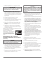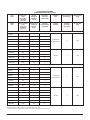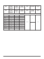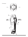
1
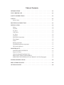
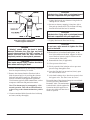
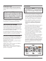
COMPRESSED AIR FILTERS
OPERATOR’S INSTRUCTION MANUAL
PC
CHE
AC
10 - 1476 scfm
5 - 1200 scfm
5 - 1200 scfm
English:
Español:
1-1
2-1
Before installation or use of the filter for the
first time, this manual should be studied
carefully to obtain a clear knowledge of the
unit and of the duties to be performed
maintaining the unit.
RETAIN THIS MANUAL WITH THE UNIT.
This technical manual contains IMPORTANT
SAFETY DATA and should be kept with the
filter at all times.
Bulletin #1341226 (193 Revision B) (2/99)
Copyright ©1999 Ingersoll-Rand Company
Table of Contents
INTRODUCTION. . . . . . . . . . . . . . . . . . . . . . . . . . . . . . . . . . . . . 1-1
TEST CERTIFICATE . . . . . . . . . . . . . . . . . . . . . . . . . . . . . . . . . . 1-1
SAFETY INSTRUCTIONS . . . . . . . . . . . . . . . . . . . . . . . . . . . . . . . 1-1
SAFETY . . . . . . . . . . . . . . . . . . . . . . . . . . . . . . . . . . . . . . . . . . 1-1
Safety Labels . . . . . . . . . . . . . . . . . . . . . . . . . . . . . . . . . . . . . 1-1
RECEIVING & INSPECTION . . . . . . . . . . . . . . . . . . . . . . . . . . . . . 1-1
INSTALLATION . . . . . . . . . . .
Piping . . . . . . . . . . . . . . .
Location . . . . . . . . . . . . . .
PC Series. . . . . . . . . . . . . .
CHE Series . . . . . . . . . . . .
AC Series . . . . . . . . . . . . .
Clearance . . . . . . . . . . . . .
Inlet/Outlet Connections. . . . . .
Filter Bypass . . . . . . . . . . . .
Drains . . . . . . . . . . . . . . .
Racking (Optional) . . . . . . . .
Wall Mounting Bracket (Optional)
.
.
.
.
.
.
.
.
.
.
.
.
.
.
.
.
.
.
.
.
.
.
.
.
.
.
.
.
.
.
.
.
.
.
.
.
.
.
.
.
.
.
.
.
.
.
.
.
.
.
.
.
.
.
.
.
.
.
.
.
.
.
.
.
.
.
.
.
.
.
.
.
.
.
.
.
.
.
.
.
.
.
.
.
.
.
.
.
.
.
.
.
.
.
.
.
.
.
.
.
.
.
.
.
.
.
.
.
.
.
.
.
.
.
.
.
.
.
.
.
.
.
.
.
.
.
.
.
.
.
.
.
.
.
.
.
.
.
.
.
.
.
.
.
.
.
.
.
.
.
.
.
.
.
.
.
.
.
.
.
.
.
.
.
.
.
.
.
.
.
.
.
.
.
.
.
.
.
.
.
.
.
.
.
.
.
.
.
.
.
.
.
.
.
.
.
.
.
.
.
.
.
.
.
.
.
.
.
.
.
.
.
.
.
.
.
.
.
.
.
.
.
.
.
.
.
.
.
.
.
.
.
.
.
.
.
.
.
.
.
.
.
.
.
.
.
.
.
.
.
.
.
.
.
.
.
.
.
.
.
.
.
.
.
.
.
.
.
.
.
.
.
.
.
.
.
.
.
.
.
.
.
.
.
.
.
.
.
.
.
.
.
.
.
.
.
.
.
.
.
.
.
.
.
.
.
.
.
.
.
.
.
1-2
1-2
1-2
1-2
1-2
1-2
1-2
1-2
1-2
1-3
1-3
1-3
∆P Switch (Optional) . . . . . . . . . . . . . . . . . . . . . . . . . . . . . . . . . 1-3
MAINTENANCE . . . . . . . . . . . . . . . . . . . . . . . . . . . . . . .
MAINTENANCE SCHEDULE . . . . . . . . . . . . . . . . . . . . . .
Inspect All Filters . . . . . . . . . . . . . . . . . . . . . . . . . . . . .
Check the Internal Float Drain Valve . . . . . . . . . . . . . . . . . . .
REPLACING THE FILTER ELEMENT . . . . . . . . . . . . . . . . .
SERVICING THE INTERNAL FLOAT DRAIN VALVE (If Equipped)
.
.
.
.
.
.
.
.
.
.
.
.
.
.
.
.
.
.
.
.
.
.
.
.
.
.
.
.
.
.
.
.
.
.
.
.
1-3
1-3
1-3
1-3
1-3
1-5
FILTER SPECIFICATIONS . . . . . . . . . . . . . . . . . . . . . . . . . . . . . . A-2
REPLACEMENT PARTS . . . . . . . . . . . . . . . . . . . . . . . . . . . . . . . . A-5
OPTIONAL PARTS . . . . . . . . . . . . . . . . . . . . . . . . . . . . . . . . . . . A-6
INTRODUCTION
Ingersoll-Rand filters will, when properly installed and
maintained, remove oil and water liquids or mist, dirt
and other particulates from compressed air.
WARNING
These filters are not designed for oxygen
service. Filtration of compressed gases or gas
mixtures other than those specified requires
specialized filters; consult a qualified systems
engineer for more information.
For best results from your Ingersoll-Rand filters, read
and follow the instructions in this manual for filter installation and element replacement.
TEST CERTIFICATE
Ingersoll-Rand certifies that each filter assembly (head
and bowl) is pressure tested to 1½ times the maximum
working pressure specified on the filter. All components
of the filter and differential pressure gauge have been
selected to comply with the highest quality standards.
Elements have been designed, manufactured, and tested
to perform at specified filtration efficiency under specific inlet conditions.
SAFETY INSTRUCTIONS
Safety instructions in this manual are bold-faced for emphasis. The signal words DANGER, WARNING, CAUTION are used to indicate hazard seriousness levels as
follows:
DANGER—Immediate hazard which WILL result in
severe injury or death.
WARNING—Hazard or unsafe practice which COULD
result in severe injury or death.
CAUTION—Hazard or unsafe practice which COULD
result in minor injury or product or property damage.
bility for the consequences of use of equipment containing non-approved parts.
2. Compressed air is dangerous. Before performing
maintenance on any component of a compressed air
system, including filters, ensure the system has been
vented to atmospheric pressure.
3. Do not use Ingersoll-Rand filters at pressures or
temperatures which exceed the maximum pressure
and temperature shown on the filter label.
4. Inspect the filter head, bowl, differential pressure
(∆P) gauge and housing, and element upon receipt
and before installing in a compressed air system. If
any component is damaged, do not install the filter.
Contact your nearest Ingersoll-Rand distributor.
5. Do not allow the transparent face on the ∆P gauge
to come in contact with methanol, gasoline, xylene,
toluene; synthetic or fire-retardant lubricants (chlorinated hydrocarbons, phosphate esters); lacquer,
aromatic or chlorinated hydrocarbon solvents; acetone or other ketones. These materials will cause the
differential pressure gauge face to dissolve or stress
crack, and may result in equipment failure.
Safety Labels
Filter labels providing important safety information are
included in this manual (Figure 1, page 1-2) and are attached to the filter itself. If any label is missing or damaged, contact your Ingersoll-Rand representative for a
replacement.
RECEIVING & INSPECTION
Upon receipt of the filter, immediately check for damage that may have occurred during shipment. If there is
any damage, do not install or attempt to repair the filter.
File a claim with the shipping company and contact
your local distributor for further instructions. Since the
filter is shipped F.O.B. Factory, the carrier is legally re-
SAFETY
WARNING
Failure to comply with the following safety
guidelines may result in equipment failure,
serious injury or death.
1. The use of replacement parts or elements other than
those supplied by Ingersoll-Rand may cause failure
of the filter, property damage or serious personal injury. Therefore, Ingersoll-Rand bears no responsiPC-Series, CHE-Series and AC-Series Filters (Bulletin 193)
Figure 1
Filter Safety Label.
1-1
sponsible for shipping damage. Such damage is not covered by the filter warranty.
afterfilters for refrigerated dryers, to remove any traces
of oil mist.
A rattling noise may or may not be heard in the assembled filter prior to installation. This is normal. The element inside the filter is held in place at the head of the
filter and by supports in the bottom of the bowl. The rattling sound is the bottom of the element moving back
and forth between those supports. Once the filter is
pressurized, the element will remain securely in place.
Note: A coalescing filter does not lower the dew
point of the compressed air. Temperature changes
downstream of the filter may result in condensation
of water and oil vapors.
INSTALLATION
Piping
Ingersoll-Rand filters must be selected on the basis of
compressed air flow rate (scfm) and pressure, not on the
basis of pipe size. Piping must also be selected based on
appropriate flow rate and pressure, and not filter connection size. The weight of all piping and filters must be
properly supported.
Connections and fittings must be rated for the maximum
operating temperature and pressure shown on the filter
nameplate or label, and must be in accordance with established engineering standards and codes.
Note: Plastic piping is never recommended for compressed air distribution.
Location
The maximum operating temperature for all
Ingersoll-Rand filters is 150°F (65°C). Install your filter
downstream of an aftercooler, or at any other location in
the system where the temperature does not exceed the
recommended maximum of 120°F (49°C). Coalescing
efficiency deteriorates rapidly above this temperature.
PC Series
These filters will remove solid particulate contamination such as pipe scale, rust, dirt and metal flakes from
your compressed air. They also provide general-purpose
removal of oil mists or liquids, and liquid water. They
can be installed as prefilters for CHE Series (High Efficiency Coalescer) or AC Series (Vapor Removal) filters, to prolong CHE and AC element life.
AC Series
Activated carbon filters remove organic vapors and their
associated tastes and smells from compressed air. When
used with PC or CHE filters, AC filters will provide
suitable compressed air for extremely demanding applications. In such applications, the air filtration system
must be maintained per the manufacturer’s instructions.
DANGER
AC filters will not convert compressed air into
breathing air. Breathing air purifiers must meet
rigid design specifications and provide outlet
air which conforms to federal and state
regulations, including carbon monoxide and
carbon dioxide levels, which are not affected
by the AC Series filters.
Clearance
Allow sufficient clearance below the filter for removal
of the filter bowl and element. Refer to page A-2 for the
required element changeout clearances.
Inlet/Outlet Connections
Inlet and outlet air connections are shown with flow direction arrows on the tops of all filter heads. Ensure air
flows through the filter in the direction specified: airflow through the filter in the wrong direction will not be
filtered properly. Refer to page A-2 for inlet and outlet
connection sizes.
Filter Bypass
A three-valve bypass installation is recommended (Figure 2), to allow isolation and depressurization of the fil-
PC Series filters are also recommended as afterfilters
for non-lubricated compressors and desiccant dryers.
CHE Series
High efficiency coalescing filters will remove virtually
all liquids and aerosol mists from your compressed air.
They should be installed as prefilters for desiccant dryers, to protect the desiccant from oil and water, and as
1-2
Figure 2
A three-valve isolation/bypass system allows
maintenance of the filter.
PC-Series, CHE-Series and AC-Series Filters (Bulletin 193)
ter for maintenance without shutting down the air
system. Support all piping to prevent stressing the filter
connections. Be sure to include a pressure bleed valve
between the isolation valves as shown, to allow venting
of internal pressure to atmosphere.
Applications which cannot tolerate unfiltered air should
have a second filter installed in the bypass loop.
Drains
All filters up to 175CHE and 300PC scfm are equipped
with internal float drains to facilitate removal of liquid
contaminants. Refer to the Filter Specifications section
for the drain connection sizes.
Filters 250CHE and 400PC scfm and larger are
equipped with manual drains as standard. Automatic
drains are available as an option. Refer to page A-6 for
the parts list.
Racking (Optional)
An optional racking feature allows two or three filters to
be joined into a single unit to provide a completely customized filter package to meet highly specialized needs.
Ingersoll-Rand filters with the same head size can be
connected directly to each other, with no additional piping and no pipe threads to leak. Refer to page A-6 for
the parts list.
A complete supply of replacement elements to meet
your compressed air filtration needs is available through
your local Ingersoll-Rand representative. Replacement
part numbers can be found on the label attached to the
filter or on page A-5.
MAINTENANCE SCHEDULE
Inspect All Filters
Inspect all filter parts during each element change, and
replace damaged or worn parts when necessary.
The particulate/coarse coalescing (50PC scfm and
higher) and high efficiency coalescing (27CHE and
higher) filters are equipped with a state-of-the-art ∆P
gauge. This gauge is calibrated to instrument-grade accuracy, and rotates in a unique “carousel” action on a
stainless steel bearing within the housing. Filters
10 – 20PC and 5 – 14CHE are equipped with a greento-red ∆P pop-up indicator. The element must be replaced once a year, or when the gauge shows fully
red (approximately 10 psid) or the pop-up indicator
changes to red.
The AC Series activated charcoal element should be replaced every six months, or when odors, tastes or vapors
are detected downstream of the filter.
Check the Internal Float Drain Valve
An optional wall mounting bracket provides additional
support for the filters. Refer to page A-6 for the parts
list.
Inspect the internal float drain valve (if equipped) every
two to three weeks for excessive oil and water by pressing the test valve on the bottom of the filter unit. If more
than one or two drops of oil leak out, the drain valve
should be cleaned or replaced as required.
DP Switch (Optional)
REPLACING THE FILTER ELEMENT
Wall Mounting Bracket (Optional)
An optional ∆P switch allows remote indication when
the filter element needs to be changed. This option is
not available for filters with a pop-up indicator. Refer to
page A-6 for the parts list.
MAINTENANCE
As contaminants are removed from the compressed air,
particulate and coalescing elements become saturated.
This saturation will cause pressure drop across the filter,
and may lead to passage of contaminants through the
filter.
Increased pressure drop reduces system efficiency,
which may damage some system components. Your
compressor will also have to work harder to overcome
the pressure drop, increasing your operating costs.
DANGER
Vent internal pressure to atmospheric
pressure before performing any maintenance.
1. Isolate the filter by opening the bypass valve (in a
three-valve installation; refer to Figure 3), and closing both isolation valves.
2. Open the pressure bleed valve to vent the filter to
atmospheric pressure.
3. Disconnect drain lines at manual and automatic
drain valves (if installed).
Regular, scheduled element changes will ensure a supply of properly filtered compressed air and keep your
operating costs low.
PC-Series, CHE-Series and AC-Series Filters (Bulletin 193)
1-3
CAUTION
Lubricate the O-ring with a petroleum-based
lubricant compatible with your application.
7. Lightly lubricate the new element O-ring before installing the new element.
8. Insert new element, snapping it into place with a
firm push up into the head. The element will hang
from the head until the bowl is installed.
CAUTION
Lubricate the O-ring with a petroleum-based
lubricant compatible with your application.
Figure 3
Side view of filter in a three-valve
isolation/bypass installation.
DANGER
A “hissing” sound while the bowl is being
removed indicates the filter has not been
properly depressurized. DO NOT continue to
remove the bowl until the filter has been
completely vented to atmospheric pressure.
CAUTION
Filter bowls may be heavy. Caution should be
taken when removing the bowl.
4. Remove the bottom bowl by unscrewing it from the
head. A strap wrench may be needed.
5. Remove the element from the filter head with a
brisk downward pull, or by working the element
back and forth until it snaps free. Discard the element in accordance with applicable regulations.
Used elements typically hold contaminants, such as
compressor lubricants and particulate matter.
Note: The element may be unsnapped by DP in
normal operation. This will not affect filtration,
as the O-ring on the element maintains a positive
seal.
9. Lightly lubricate the filter bowl O-ring.
CAUTION
Do not use a pipe wrench to tighten the filter
bowl to the head.
10. Reattach bowl to head and hand tighten. As the
bowl is threaded onto the head, supports in the bottom of the bowl ensure a proper seal between the
element and the filter head.
11. Reattach drain lines (if applicable).
12. Close pressure bleed valve.
13. Slowly open the inlet isolation valve to prevent a
pressure surge through the filter.
14. Once the filter has been pressurized, slowly open
the outlet isolation valve.
15. After both isolation valves have been opened, close
the bypass valve. The filter is now in service.
Record the date of the element change in a record book
or on the provided “Maintenance
Reminder” label. The maintenance MAINTENANCE REMINDER
reminder label with the updated information should be applied over
the previous label each time the element is replaced.
Date Element Changed:
Changed By:
Next Scheduled Change:
Additional elements available from your local
Ingersoll-Rand Compressed Air System supplier
Telephone:
Fax:
6. Clean accumulated debris from the bowl with soap
and water, and dry thoroughly.
1-4
PC-Series, CHE-Series and AC-Series Filters (Bulletin 193)
SERVICING THE INTERNAL FLOAT DRAIN
VALVE (If Equipped)
Note: For filters 20 scfm and less, the float drain
may not stay in one piece when removing from
the filter bowl. Be sure to keep both pieces of the
drain together if not replacing drain.
DANGER
Vent internal pressure to atmospheric
pressure before performing any maintenance.
6. Turn the bowl upside down. The float drain will fall
out.
1. To isolate the filter, open the bypass valve (in a
three-valve installation; refer to Figure 3, page 6)
and close both isolation valves.
7. Inspect the drain for damage. Replace if necessary
or clean with a mild soap and water. Do not use solvents to clean the drain valve as they may damage
the valve.
2. Open the pressure bleed valve to vent the filter to
atmospheric pressure.
3. Disconnect drain lines and automatic drain valves
(if installed).
DANGER
A “hissing” sound while the bowl is being
removed indicates the filter has not been
properly depressurized. DO NOT continue to
remove the bowl until the filter has been
completely vented to atmospheric pressure.
4. Remove the bottom bowl by unscrewing it from the
head. A strap wrench may be needed.
5. Remove the nut from the bottom of the bowl.
Note: For filters 20 scfm and less, be sure both
pieces of the float drain are intact before replacing the nut.
8. Hold the bowl upright and drop in the new or
cleaned drain so that the drain stem is through the
hole at the bottom of the filter.
9. Replace the nut and hand tighten.
10. Reattach bowl to head and hand tighten.
11. Reattach the drain line (if applicable).
12. Close pressure bleed valve.
13. Slowly open the inlet isolation valve to prevent a
pressure surge through the filter.
14. Once the filter has been pressurized, slowly open
the outlet isolation valve.
15. After both isolation valves have been opened, close
the bypass valve. The filter is now in service.
PC-Series, CHE-Series and AC-Series Filters (Bulletin 193)
1-5
FILTROS PARA AIRE COMPRIMIDO
MANUAL DE INSTRUCCIONES
PC
CHE
AC
10 - 1476 scfm
5 - 1200 scfm
5 - 1200 scfm
Antes de instalar o usar el filtro por primera
vez, este manual debe ser estudiado
cuidadosamente para obtener un claro
conocimiento de la unidad y de los requisitos
de mantenimiento de la unidad.
MANTENGA ESTE MANUAL JUNTO CON LA
UNIDAD.
Este manual técnico contiene DATOS
IMPORTANTES DE SEGURIDAD y debe ser
mantenido junto con el filtro todo el tiempo.
Serie PC, Serie CHE y Serie AC (Boletín 193)
Boletín 1341226 (193 Revisión B) (2/99)
Copyright ©1999 Ingersoll-Rand Company
2-1
Tabla de Contenidos
INTRODUCCION . . . . . . . . . . . . . . . . . . . . . . . . . . . . . . . . . . . . 2-3
CERTIFICADO DE PRUEBA . . . . . . . . . . . . . . . . . . . . . . . . . . . . . . 2-3
INSTRUCCIONES DE SEGURIDAD. . . . . . . . . . . . . . . . . . . . . . . . . . 2-3
SEGURIDAD . . . . . . . . . . . . . . . . . . . . . . . . . . . . . . . . . . . . . . . 2-3
Calcomanías de Seguridad. . . . . . . . . . . . . . . . . . . . . . . . . . . . . . . 2-4
RECEPCION E INSPECCION . . . . . . . . . . . . . . . . . . . . . . . . . . . . . 2-4
INSTALACION . . . . . . . . . . . . . . . . . .
Tubería. . . . . . . . . . . . . . . . . . . . .
Ubicación . . . . . . . . . . . . . . . . . . .
Serie PC . . . . . . . . . . . . . . . . . . . .
Serie CHE . . . . . . . . . . . . . . . . . . .
Serie AC . . . . . . . . . . . . . . . . . . . .
Espacio Libre . . . . . . . . . . . . . . . . .
Conexiones de Entrada/Salida . . . . . . . . .
Desvío del Filtro . . . . . . . . . . . . . . . .
Drenajes . . . . . . . . . . . . . . . . . . . .
Sistema de Montaje (Opcional) . . . . . . . .
Abrazadera de montaje a la pared (Opcional) .
.
.
.
.
.
.
.
.
.
.
.
.
.
.
.
.
.
.
.
.
.
.
.
.
.
.
.
.
.
.
.
.
.
.
.
.
.
.
.
.
.
.
.
.
.
.
.
.
.
.
.
.
.
.
.
.
.
.
.
.
.
.
.
.
.
.
.
.
.
.
.
.
.
.
.
.
.
.
.
.
.
.
.
.
.
.
.
.
.
.
.
.
.
.
.
.
.
.
.
.
.
.
.
.
.
.
.
.
.
.
.
.
.
.
.
.
.
.
.
.
.
.
.
.
.
.
.
.
.
.
.
.
.
.
.
.
.
.
.
.
.
.
.
.
.
.
.
.
.
.
.
.
.
.
.
.
.
.
.
.
.
.
.
.
.
.
.
.
.
.
.
.
.
.
.
.
.
.
.
.
.
.
.
.
.
.
.
.
.
.
.
.
.
.
.
.
.
.
.
.
.
.
.
.
.
.
.
.
.
.
.
.
.
.
.
.
.
.
.
.
.
.
.
.
.
.
.
.
.
.
.
.
.
.
.
.
.
.
.
.
2-4
2-4
2-4
2-4
2-4
2-4
2-4
2-5
2-5
2-5
2-5
2-5
Interruptor ∆P (Opcional) . . . . . . . . . . . . . . . . . . . . . . . . . . . . . . . 2-5
MANTENIMIENTO . . . . . . . . . . . . . . . . . . . . .
PROGRAMA DE MANTENIMIENTO . . . . . . . . .
Inspeccione Todos los Filtros . . . . . . . . . . . . . . .
Verifique la Válvula Interna de Drenaje Tipo Flotador . .
REEMPLAZO DEL ELEMENTO DE FILTRO . . . . .
MANTENIMIENTO DE LA VALVULA
INTERNA DE DRENAJE TIPO FLOTADOR (si se usa)
.
.
.
.
.
.
.
.
.
.
.
.
.
.
.
.
.
.
.
.
.
.
.
.
.
.
.
.
.
.
.
.
.
.
.
.
.
.
.
.
.
.
.
.
.
.
.
.
.
.
.
.
.
.
.
.
.
.
.
.
.
.
.
.
.
.
.
.
.
.
2-5
2-5
2-5
2-6
2-6
. . . . . . . . . . . . . . 2-7
ESPECIFICACIONES DE FILTROS . . . . . . . . . . . . . . . . . . . . . . . . . A-2
PIEZAS DE REPOSICIÓN . . . . . . . . . . . . . . . . . . . . . . . . . . . . . . . A-5
PIEZAS OPCIONALES . . . . . . . . . . . . . . . . . . . . . . . . . . . . . . . . . A-6
2-2
Serie PC, Serie CHE y Serie AC (Boletín 193)
INTRODUCCION
Los filtros Ingersoll-Rand, cuando están apropiadamente instalados y atendidos, remueven aceite y agua
líquida o neblina, suciedad y partículas del aire comprimido.
AVISO
Estos filtros no están diseñados para oxígeno.
El filtrado de gases comprimidos o mezclas de
gases diferentes a los especificados, requiere
de filtros especializados; consulte un
ingeniero de sistemas de aire/gas comprimido
calificado para obtener más información.
Para mejores resultados con sus filtros Ingersoll-Rand,
lea y siga las instrucciones en este manual para la instalación del filtro y el mantenimiento del elemento.
CERTIFICADO DE PRUEBA
Ingersoll-Rand certifica que cada conjunto de filtrado
(carcaza y tapa) es probado a una presión de 1½ veces
la presión máxima de trabajo especificada en el filtro.
Todos los componentes del filtro y del manómetro de
presión diferencial han sido seleccionados para cumplir
con los más altos estándares de calidad.
Los elementos han sido diseñados, fabricados y probados para desempeñarse a la eficiencia de filtrado especificada bajo condiciones de admisión determinadas.
INSTRUCCIONES DE SEGURIDAD
Las instrucciones de seguridad en este manual están impresas en negrilla. Las palabras claves PELIGRO, AVISO, PRECAUCION se usan para indicar diferentes
niveles de riesgo como sigue:
PELIGRO—Riesgo inmediato que RESULTARA en
lesiones graves o muerte.
SEGURIDAD
AVISO
E l inc um p l im ie nt o d e l as sig u i e n te s
recomendaciones de seguridad pueden
resultar en falla del equipo, lesiones serias o
muerte.
1. El uso de partes de reemplazo o elementos diferentes de los suministrados por Ingersoll-Rand pueden
causar la falla del filtro, daño a la propiedad o lesiones personales graves. Por lo tanto, Ingersoll-Rand
no se hace responsable por las consecuencias del
uso de equipo que contenga partes no aprobadas.
2. El aire comprimido es peligroso. Antes de hacer
mantenimiento a cualquier componente de un
sistema de aire comprimido, incluyendo filtros,
asegúrese que se haya aliviado la presión del
sistema.
3. No use filtros Ingersoll-Rand a presiones o temperaturas que exceden la presión o la temperatura
máxima impresa en la calcomanía del filtro.
4. Inspeccione la tapa del filtro, carcaza, el manómetro
de presión diferencial y el elemento cuando reciba
estos componentes y antes de instalarlos en el
sistema de aire comprimido. Si cualquier componente está averiado, no instale el filtro. Contacte a
su distribuidor Ingersoll-Rand.
5. No permita que la cara transparente del manómetro
∆P esté en contacto con metanol, gasolina, xileno,
tolueno, lubricantes sintéticos o retardantes de
fuego (cloruros de hidrocarburo, fosfato-ésteres); lacas, solventes aromáticos o con base cloruros de hidrocarbono, o acetonas. Estos materiales causarán
que la cara del manómetro de presión diferencial se
disuelva o se rompa bajo presión, causando una
falla del equipo.
AVISO—Riesgo o práctica insegura que PODRIA resultar en lesiones graves o muerte.
PRECAUCION—Riesgo o práctica insegura que
PODRIA resultar en lesiones menores o en daños al
producto o a la propiedad.
Figura 1
Etiqueta de Seguridad del Filtro
Serie PC, Serie CHE y Serie AC (Boletín 193)
2-3
Calcomanías de Seguridad
En este manual se incluyen ejemplos de las calcomanías
de los filtros que proveen importante información de seguridad (Figura 1, pág. 2-2). Si cualquier calcomanía
está incompleta o perdida, contacte a su distribuidor
Ingersoll-Rand para obtener un reemplazo.
RECEPCION E INSPECCION
Después de recibir el filtro, verifique inmediatamente
que no haya recibido daños durante el transporte. Si hay
algún daño, no instale o intente reparar el filtro. Inicie
un reclamo con la compañía de transporte y contacte su
distribuidor local para obtener instrucciones. Los daños
por transporte no están cubiertos por la garantía del filtro y en cualquier caso, el transportador es legalmente
responsable por cualquier avería.
Es posible que se perciba un ruido en el conjunto del filtro antes de instalarlo. Esto es normal. El elemento dentro del filtro es mantenido en su lugar por medio de la
tapa del filtro y por soportes en el fondo de la carcaza.
El ruido proviene de la parte inferior del elemento al
moverse entre los soportes. Una vez que el filtro está
presurizado, el elemento se mantendrá asegurado en posición.
INSTALACION
Tubería
Los filtros Ingersoll-Rand deben ser seleccionados de
acuerdo con el flujo de aire comprimido (scfm) y la presión, no de acuerdo con el tamaño de la tubería. La tubería debe ser seleccionada también de acuerdo con el
flujo de aire y la presión, y no según el tamaño de conexión del filtro. El peso de la tubería y del filtro deben
ser apropiadamente soportados.
Las conexiones y acoples deben estar seleccionadas
para operar a la temperatura y presión máximas que se
muestran en la identificación o la calcomanía del filtro y
deben estar de acuerdo con estándares y códigos establecidos de ingeniería.
Nota: Nunca es recomendable usar tubería plástica
para distribución de aire comprimido.
Ubicación
La temperatura de operación máxima para todos los filtros Ingersoll-Rand es 150°F (65°C). Instale el filtro
corriente abajo de un postenfriador, o en cualquier otro
lugar en el sistema donde la temperatura no exceda la
máxima recomendada de 120°F (49°C). La eficiencia de
2-4
coalescencia se deteriora rápidamente por encima de
esta temperatura.
Serie PC
Estos filtros remueven contaminación en forma de
partículas sólidas como escamas de tubería, óxido, suciedad y metal del aire comprimido. También sirven
como filtros de propósito general para remover aceite
líquido o en neblina y agua líquida. Pueden ser instalados como prefiltros de la Serie CHE (Coalescente de
Alta Eficiencia) o de la Serie AC (Remoción de vapores), para prolongarla vida de los elementos CHE y
AC.
Los filtros Serie PC se recomiendan también como postfiltros para compresores no lubricados y con secadores
por desecante.
Serie CHE
Los filtros coalescentes de alta eficiencia remueven virtualmente todos los líquidos y aerosoles del aire comprimido. Deben ser instalados como prefiltros con
secadores por desecante, para proteger el desecante del
agua y el aceite, y como postfiltros con secadores refrigerados para remover cualquier traza de neblina de
aceite.
Nota: Un filtro coalescente no reduce el punto de
rocío del aire comprimido. Cambios de temperatura
corriente abajo del filtro puede causar condensación
de vapores de agua o aceite.
Serie AC
Los filtros de carbón activado remueven vapores orgánicos y sabores y olores asociados del aire comprimido.
Cuando se usan con filtros PC o CHE, los filtros AC
suministrarán aire comprimido adecuado para las aplicaciones más exigentes. En tales aplicaciones, el
sistema de filtrado de aire debe ser mantenido de acuerdo a las instrucciones del fabricante.
PELIGRO
Los filtros AC no convierten el aire comprimido
en aire respirable. Los purificadores de aire
r e sp ir ab l e
deben
c um p l ir
rí gi d a s
especificaciones de diseño y proveer aire a la
descarga que sigue regulaciones federales y
estatales, incluyendo niveles de monóxido y
de dióxido de carbono, los cuales no son
modificados por los filtros Serie AC.
Espacio Libre
Permita suficiente espacio libre debajo del filtro para remover la carcaza del filtro y el elemento. Refiérase a la
Serie PC, Serie CHE y Serie AC (Boletín 193)
página A-2 para obtener el espacio libre requerido para
cambiar el elemento.
Conexiones de Entrada/Salida
Las conexiones de entrada y salida de aire se muestran
por medio de flechas en la parte superior de la tapa del
filtro. Asegúrese que el aire fluye a través del filtro en la
dirección especificada. Aire fluyendo en la dirección incorrecta a través del filtro, no será filtrado apropiadamente. Refiérase a la página A-2 para los tamaños de las
conexiones.
Desvío del Filtro
Se recomienda la instalación de una válvula de desvío
de tres vías (Figura 2), para permitir la despresurización
del filtro para mantenimiento sin inhabilitar el sistema.
Soporte toda la tubería para prevenir esfuerzos en las
conexiones del filtro. Asegúrese de incluir una válvula
de alivio de presión entre las válvulas de aislamiento tal
como se muestra, para permitir el alivio de presión interna a la atmósfera.
Las aplicaciones que no pueden operar sin aire filtrado,
deben tener un segundo filtro instalado en paralelo.
Drenajes
Todos los filtros hasta los modelos 175CHE y 300PC
están equipados con drenajes internos tipo flotador para
facilitar la eliminación de contaminantes líquidos. Refiérase a la página A-2 para el tamaño de la conexión de
drenaje.
Los filtros a partir del 250CHE y 400PC están equipados con drenajes manuales como estándar. El drenaje
automático está disponible como opción. Refiérase a la
página A-6 para lista de partes opcionales.
Sistema de Montaje (Opcional)
Por medio de un sistema opcional se pueden instalar dos
o tres filtros juntos como una unidad para proveer un
paquete de filtrado diseñado para cumplir con aplicaciones altamente especializadas. Los filtros Ingersoll-Rand
que tengan el mismo tamaño de tapa pueden ser conectados directamente uno a otro sin tubería adicional ni
conexiones roscadas que puedan tener fugas. Refiérase
a la página A-6 para lista de partes opcionales.
Abrazadera de montaje a la pared
(Opcional)
Usando una abrazadera opcional de montaje a la pared
se puede lograr soporte adicional para los filtros. Refiérase a la página A-6 para lista de partes opcionales.
Interruptor DP (Opcional)
Por medio de un interruptor ∆P opcional se puede obtener indicación remota cuando el elemento de filtro necesita ser reemplazado. Esta opción no está disponible en
filtros con indicador de servicio tipo burbuja. Refiérase
a la página A-6 para lista de partes opcionales.
MANTENIMIENTO
A medida que los contaminantes son removidos del aire
comprimido, los elementos coalescentes y de partículas
se saturan. Esta saturación causa una caída presión a
través del filtro y puede provocar el paso de contaminantes a la red de aire.
Un incremento en la caída de presión reduce la eficiencia del sistema, lo cual puede averiar algunos componentes del sistema. Su compresor tendrá que trabajar
más para recuperar la caída de presión, incrementando
los costos de operación.
El reemplazo periódico y programado de los elementos
asegurará un suministro apropiado de aire comprimido
filtrado y mantendrá bajos los costos de operación.
A través de su distribuidor local de Ingersoll-Rand
puede obtener un suministro completo de elementos de
reemplazo para cumplir con sus necesidades de filtración de aire comprimido. Los números de parte de reemplazo se pueden encontrar en la calcomanía del filtro
o en la página A-5.
PROGRAMA DE MANTENIMIENTO
Inspeccione Todos los Filtros
Figura 2
Una válvula de aislamiento y desvío del sistema
permite el mantenimiento del filtro.
Serie PC, Serie CHE y Serie AC (Boletín 193)
Inspeccione todas las partes del filtro durante el cambio
del elemento y reemplace las partes dañadas o desgastadas cuando sea necesario.
2-5
Los filtros de partículas/propósito general (a partir del
50PC) y los coalescentes de alta eficiencia (a partir del
27CHE) están equipados con un avanzado manómetro
∆P. Este manómetro está calibrado para proveer
precisión de instrumento y gira sobre un rodamiento de
acero inoxidable dentro de la carcaza. Los filtros de
10 – 20PC y 5 – 14CHE están equipados con un
indicador ∆P tipo burbuja que cambia de verde a rojo.
El elemento debe ser reemplazado una vez al año, o
cuando el manómetro esté totalmente en la zona roja
(aproximadamente 10 psid) o cuando el indicador de
burbuja cambie a rojo.
Los elementos de la Serie AC de carbón activado deben
ser reemplazados cada seis meses o cuando sea posible
detectar olores, sabores o vapores corriente abajo del filtro.
Verifique la Válvula Interna de Drenaje Tipo
Flotador
Inspeccione la válvula interna de drenaje tipo flotador
(si se usa) cada dos o tres semanas para detectar una excesiva cantidad de aceite o agua, presionando la válvula
de prueba en la parte inferior del filtro. Si salen más de
dos o tres gotas de aceite, la válvula de drenaje debe ser
limpiada o reemplazada si se requiere.
REEMPLAZO DEL ELEMENTO DE FILTRO
PELIGRO
Alivie la presión interna a la atmósfera antes de
llevar a cabo cualquier mantenimiento.
1. Aísle el filtro abriendo la válvula de desvío (en una
instalación con tres válvulas; refiérase a la Figura
3), y cerrando ambas válvulas de aislamiento.
2. Abra la válvula de alivio de presión para liberar la
presión del filtro a la atmósfera.
3. Desconecte las líneas de drenaje de las válvulas de
drenaje manual y automática (si se usa).
PELIGRO
Cuando se escucha un “silbido” al remover la
carcaza, significa que el filtro no ha sido
apropiadamente despresurisado. NO continúe
removiendo la carcaza hasta que la presión en
el filtro no haya sido totalmente aliviada a la
atmósfera.
PRECAUTION
La carcaza puede ser pesada. Debe ser
cuidosamente removida.
4. Remueva la parte inferior de la carcaza desenroscándola de la parte superior. Es posible que se requiera una llave de correa.
5. Remueva el elemento de la parte superior del filtro
tirando de él hacia abajo. Descarte el elemento de
acuerdo con las regulaciones aplicables. Los elementos usados usualmente contienen contaminantes
como lubricantes de compreso y partículas sólidas.
Nota: El elemento puede ser desasegurado por
presión diferencial en operación normal. Esto no
afectará la filtración debido a que el “O”-ring en
el elemento mantendrá un sello positivo.
6. Limpie cualquier acumulación de suciedad de la
carcaza con agua y jabón y seque completamente.
PRECAUCION
Lubrique el “O”-ring con lubricante a base de
p e t r ó l e o q ue s e a c o m p at ib l e co n s u
aplicación.
7. Lubrique ligeramente el nuevo elemento “O”-ring
antes de instalar el nuevo elemento.
8. Inserte el nuevo elemento asegurándolo firmemente
en su lugar en la parte superior de la carcaza. El elemento quedará colgando de la tapa del filtro hasta
que se instale la carcaza.
Figura 3
Vista lateral del filtro en una instalación de
3-válvulas de aislamiento/desvío.
2-6
PRECAUCION
Lubrique el “O”-ring con lubricante a base de
p e t r ó l e o q ue s e a c o m p at ib l e co n s u
aplicación.
Serie PC, Serie CHE y Serie AC (Boletín 193)
9. Lubrique ligeramente el “O”-ring de la carcaza.
PRECAUCION
No utilice una llave de tubo para adjustar la
carcaza del filtro al cabezal del mismo.
10. Reinstale la carcaza en la tapa y apriete con la
mano. A medida que la carcaza es enroscada en la
tapa, los soportes en el fondo de la carcaza aseguran
que exista un sello apropiado entre el elemento y la
tapa del filtro.
11. Reinstale la líneas de drenaje (si se usan)
12. Cierre la válvula de alivio de presión.
13. Abra lentamente la válvula de aislamiento para prevenir un pico de presión a través del filtro.
14. Una vez que el filtro haya sido presurizado, abra
lentamente la válvula de aislamiento del lado de
descarga.
PELIGRO
Cuando se escucha un “silbido” al remover la
carcaza, significa que el filtro no ha sido
apropiadamente despresurisado. No continúe
removiendo la carcaza hasta que la presión en
el filtro no haya sido totalmente aliviada a la
atmósfera.
4. Remueva la parte inferior de la carcaza desenroscándola de la parte superior. Es posible que se requiera una llave de correa.
5. Remueva la tuerca de la parte inferior de la carcaza.
Nota: Para filtros de menos de 20 scfm, es posible que el flotador de drenaje no permanezca en
una pieza cuando sea removido de la carcaza del
filtro. Asegúrese de mantener las piezas del drenaje juntas si no las va a reemplazar.
6. Gire la carcaza hacia abajo. El flotador de drenaje
caerá por sí solo.
15. Después de que ambas válvulas de aislamiento
estén abiertas, cierre la válvula de desvío. El filtro
está ahora en operación.
Registre la fecha de reemplazo del elemento en el libro
de mantenimiento o en la calcomanía de “Recordatorio de
MAINTENANCE REMINDER
Mantenimiento.” Esta calcomanía
con la información actualizada,
debe ser aplicada sobre la anterior
cada vez que se reemplace el elemento.
7. Verifique que el drenaje no tenga daños. Reemplácelo si es necesario o límpielo con agua y jabón
suave. No use solventes para limpiar la válvula de
drenaje debido a que puede dañarla.
MANTENIMIENTO DE LA VALVULA
INTERNA DE DRENAJE TIPO FLOTADOR
(si se usa)
9. Ponga la tuerca y apriétela a mano.
Date Element Changed:
Changed By:
Next Scheduled Change:
Additional elements available from your local
Ingersoll-Rand Compressed Air System supplier
Telephone:
Fax:
PELIGRO
Alivie la presión interna a la atmósfera antes de
llevar a cabo cualquier mantenimiento.
1. Aísle el filtro abriendo la válvula de desvío (en una
instalación con tres válvulas; refiérase a la Figura
3), y cerrando ambas válvulas de aislamiento.
2. Abra la válvula de alivio de presión para liberar la
presión del filtro a la atmósfera.
3. Desconecte las líneas de drenaje de las válvulas de
drenaje manual y automática (si se usa).
Serie PC, Serie CHE y Serie AC (Boletín 193)
Nota: Para filtros de menos de 20 scfm,
asegúrese que ambas piezas del flotador de drenaje estén intactas antes de reemplazar la tuerca.
8. Mantenga la carcaza en posición vertical y deje caer
el drenaje limpio o nuevo de tal manera que el
vástago del drenaje pasa a través del agujero al
fondo del filtro.
10. Reinstale la carcaza en la tapa del filtro y apriete a
mano.
11. Reinstale la línea de drenaje (si se usa).
12. Cierre la válvula de alivio de presión.
13. Abra lentamente la válvula de aislamiento para prevenir un pico de presión a través del filtro.
14. Una vez que el filtro haya sido presurizado, abra
lentamente la válvula de aislamiento del lado de
descarga.
15. Después de que ambas válvulas de aislamiento
estén abiertas, cierre la válvula de desvío. El filtro
está ahora en operación.
2-7
FILTER SPECIFICATIONS
ESPECIFICACIONES DE FILTROS
REPLACEMENT PARTS
PIEZAS DE REPOSICIÓN
OPTIONAL PARTS
PIEZAS OPCIONALES
PC-Series, CHE-Series and AC-Series Filters (Bulletin 193)
A-1
FILTER SPECIFICATIONS
ESPECIFICACIONES DE FILTROS
Filter
Model
Design Flow
(scfm)
(at 100 psig
operating
pressure)
Element
Changeout
Clearance
(inches)
Inlet/Outlet
Connection
(inches NPT)
Standard
Drain
Drain Connection
(inches NPT)
Max. Pressure
(psig)
Model
Filtro
Flujo de Diseño
(scfm)
(a 100 psig
Pressão de
Operação
Espacio para
Cambio del
Elemento
(pulg.)
Conexión
Entrada/Salida
(pulg. NPT)
Drenaje
Estándar
Conexión
de Drenaje
(plug. NPT)
Presión Max.
(psig)
1¤8
250a
½
300
1¤8
250a
½
300
CHE Series (Serie CHE)
IR5CHE
5
4
¼
IR14CHE
14
6
3¤8
IR27CHE
27
7
½
Internal Float
IR56CHE
56
11
¾
Flotador Interno
IR100CHE
100
9
IR175CHE
175
14
1¼
IR250CHE
250
12
1½
IR450CHE
450
20
2
IR600CHE
600
23
2½
IR750CHE
750
28
2½
IR1000CHE
1,000
33
3
IR1200CHE
1,200
38
3
1
Manual
PC Series (Serie PC)
a
IR10PC
10
4
3¤8
IR20PC
20
6
3¤8
IR50PC
50
7
½
IR56PC
56
7
¾
Internal Float
IR100PC
100
11
¾
Flotador Interno
IR150PC
150
9
1
IR175PC
175
9
1¼
IR300PC
300
14
1¼
IR400PC
400
12
1½
IR450PC
450
12
2
IR600PC
600
20
2
IR800PC
800
23
2½
IR1000PC
1,000
28
3
IR1200PC
1,200
33
3
IR1476PC
1,476
38
3
Manual
Maximum pressure is 300 psig when the internal float drain is removed.
La presión máxima es 300 psig cuando se remueve la válvula de drenaje de flotador interna.
A-2
PC-Series, CHE-Series and AC-Series Filters (Bulletin 193)
Filter
Model
Design Flow
(scfm)
(at 100 psig
operating
pressure)
Element
Changeout
Clearance
(inches)
Inlet/Outlet
Connection
(inches NPT)
Standard
Drain
Drain Connection
(inches NPT)
Max. Pressure
(psig)
Model
Filtro
Flujo de Diseño
(scfm)
(a 100 psig
Pressão de
Operação
Espacio para
Cambio del
Elemento
(pulg.)
Conexión
Entrada/Salida
(pulg. NPT)
Drenaje
Estándar
Conexión
de Drenaje
(plug. NPT)
Presión Max.
(psig)
AC Series (Serie AC)
IR5AC
5
4
¼
IR14AC
14
6
3¤8
IR27AC
27
7
½
IR56AC
56
11
¾
IR100AC
100
9
IR175AC
175
14
1¼
IR250AC
250
12
1½
IR450AC
450
20
2
IR600AC
600
23
2½
IR750AC
750
28
2½
IR1000AC
1,000
33
3
IR1200AC
1,200
38
3
PC-Series, CHE-Series and AC-Series Filters (Bulletin 193)
1¤8
1
300
Manual
½
A-3
FILTER CUTAWAY
A-4
PC-Series, CHE-Series and AC-Series Filters (Bulletin 193)
REPLACEMENT PARTS
PIEZAS DE REPOSICIÓN
*
1
2
3
4
5
*
*
Filter Model
Complete
Filter
Assembly
Replacement
Element
Filter Bowl
O-Ring
Internal Float
Drain Valve
∆P Gauge/
Indicator
ADV Adapter
Recommended Element
Changeout Schedule
Modelo
Filtro
Conjunto
Completo
del Filtro
Elemento
de
Reemplazo
“O”-ring de
la Carcaza
Válvula de
Drenaje de
Flotador
Indicador/
Manómetro
∆P
Adaptador
ADV
Cronograma de
Cambio del Elementro
CHE Series (Serie CHE)
IR5CHE
39240312
39240874
IR14CHE
39240320
39240882
IR27CHE
39240338
39240890
IR56CHE
39240346
39240908
IR100CHE
39240353
39240916
IR175CHE
39240361
39240924
IR250CHE
39240379
39240932
IR450CHE
39240387
39240940
IR600CHE
39240395
39240957
IR750CHE
39240403
39240965
IR1000CHE
39240411
39240973
IR1200CHE
39240429
39240981
39250402
39241567
39241542
39244959
39241575
39241559
39244959
Once a year or when the pop-up indicator changes to red.
1 vez/año o caundo el indicador
cambie a rojo.
39250410
39250428
Once a year or when the gauge
shows fully red (approximately 10
psid).
39250436
1 vez/año o cuando el manómetro
pase completamente a rojo (aprox.
10 psid).
39241559
39250444
PC Series (Serie PC)
IR10PC
39240601
39241070
IR20PC
39240619
39241088
IR50PC
39240627
39241096
IR56PC
39240635
39241104
IR100PC
39240643
39241112
IR150PC
39240650
39241120
IR175PC
39240668
39241138
IR300PC
39240676
39241146
IR400PC
39240684
39241153
IR450PC
39240692
39241161
IR600PC
39240700
39241179
IR800PC
39240718
39241187
IR1000PC
39240726
39241195
IR1200PC
39240734
39241203
IR1476PC
39240742
39241211
39250402
39241567
39241542
39244959
39241575
39241559
39244959
Once a year or when the pop-up indicator changes to red.
1 vez/año o caundo el indicador
cambie a rojo.
39250410
39250428
Once a year or
when the gauge shows fully red
(approximately 10 psid).
1 vez/año o cuando el manómetro
pase completamente a rojo (aprox.
10 psid).
39250436
39241559
39250444
AC Series (Serie AC)
IR5AC
39240759
39241328
IR14AC
39240767
39241336
IR27AC
39240775
39241351
IR56AC
39240783
39241369
IR100AC
39240791
39241377
IR175AC
39240809
39241385
IR250AC
39240817
39241393
IR450AC
39240825
39241401
IR600AC
39240833
39241419
IR750AC
39240841
39241427
IR1000AC
39240858
39241435
IR1200AC
39240866
39241443
39250402
39250410
39250428
Every six months or when odors,
tastes or vapors are detected downstream of the filter.
39250436
Cada 6 meses o cuando olores, sabores o vapores sean detectados
corriente abajo del filtro.
39250444
PC-Series, CHE-Series and AC-Series Filters (Bulletin 193)
A-5
OPTIONAL PARTS
PIEZAS OPCIONALES
Filter
Model
Modelo
Filtro
Automatic Drain Valves 1
ADV-1711,
Electronic,
¼ in. NPT,
115/1/60
ADV-1811,
Electronic,
½ in. NPT,
115/1/60
SSDV-1,
Pneumatic,
½ in. NPT
Válvula de Drenaje Automática1
ADV-1711,
Eletrónica,
¼ pulg. NPT,
115/1/60
ADV-1811,
Eletrónica,
½ pulg. NPT,
115/1/60
SSDV-1,
Neumática,
½ pulg. NPT
Wall Mount
Bracket
Dual
Racking Kit
Triple Racking
Kit
∆P Switch
Sistema de
Montaje en la
Pared
Dual
Sistema de
Ensamble
Triple
Sistema de
Ensamble
Interruptor
DP
CHE Series (Serie CHE)
IR5CHE
IR14CHE
IR27CHE
IR56CHE
IR100CHE
IR175CHE
IR250CHE
IR450CHE
39540026
39558499
39218276
39250279
39250329
39250360
39540026
39558499
39218276
39250287
39250337
39250378
39250097
39540026
39558499
39218276
39250295
39250345
39250386
39250097
39540026
39558499
39218276
39250303
39250352
39250394
39250097
39540026
39558499
39218276
39250311
IR600CHE
IR750CHE
IR1000CHE
39250097
IR1200CHE
PC Series (Serie PC)
IR10PC
IR20PC
39540026
39558499
39218276
39250279
39250329
39250360
39540026
39558499
39218276
39250287
39250337
39250378
39250097
39540026
39558499
39218276
39250295
39250345
39250386
39250097
39540026
39558499
39218276
39250303
39250352
39250394
39250097
39540026
39558499
39218276
39250311
IR50PC
IR56PC
IR100PC
IR150PC
IR175PC
IR300PC
IR400PC
IR450PC
IR600PC
IR800PC
IR1000PC
IR1200PC
39250097
IR1476PC
AC Series (Serie AC)
IR5AC
IR14AC
IR27AC
IR56AC
IR100AC
IR175AC
IR250AC
IR450AC
39540026
39558499
39218276
39250279
39250329
39250360
39540026
39558499
39218276
39250287
39250337
39250378
39250097
39540026
39558499
39218276
39250295
39250345
39250386
39250097
39540026
39558499
39218276
39250303
39250352
39250394
39250097
39540026
39558499
39218276
39250311
IR600AC
IR750AC
IR1000AC
39250097
IR1200AC
1
ADV adapter is required to install automatic drain valves. Refer to the replacement parts list for the ADV adapter parts list.
Se requiere el adaptador ADV para instalar las válvulas de drenaje automáticas. Refiérase a la piezas de reposición para los adaptadores de la válvula ADV.
A-6
PC-Series, CHE-Series and AC-Series Filters (Bulletin 193)