1
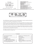
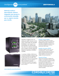
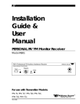
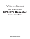
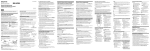
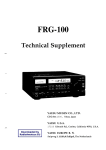
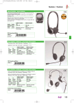
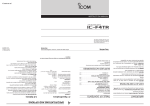
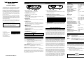
CONTROLS & CONNECTORS
Front Panel
VXR-1000
SPECIFICATIONS
GENERAL
Rear Panel
Frequency Range:
OPERATING MANUAL
The VXR-1000 Series is designed to provide extended
handheld coverage by repeating transmissions in both directions through an existing high power mobile radio.
Reliability is assured by a highly integrated surface mount
circuit design and a aluminum extrusion chassis. Important channel frequency data is stored in EEPROM, and is
easily programmable by dealers using a personal computer and the Vertex Standard VPL-1 Programming Cable
and CE-22 Software.
Please take a few minutes to read this manual carefully.
The information presented here will allow you to derive
maximum performance from your VXR-1000. After reading it, keep the manual handy for quick reference, in case
questions arise later on.
We’re glad you joined the Vertex Standard team. Call on
us any time, because our business is communications.
Let us help you get your message across.
Microphone Jack
Connect the microphone plug to this jack.
CHANNEL Selector Knob
This knob selects the operating channel.
PRI Indicator
When on, “PRI” indicates that the unit is at priority count
zero and will repeat all transmissions.
TX Indicator
When on, “TX” indicates that the repeater is transmitting to
the handheld.
COR Indicator
This lamp blinks red when the VXR-1000 is receiving a signal from a handheld, and glows red while the VXR-1000 is
receiving a sub-audible tone from the handheld.
This device complies with Part 15 of the FCC rules.
Operation is subject to the condition that this device does not cause harmful interference.
PWR Indicator
This is the main “POWER ON” indicator for the VXR-1000.
VOLUME Knob
This knob adjusts the receiver volume.
E
1
3
3
7
7
No portion of this manual
may be reproduced
without the permission of
Vertex Standard LMR, Inc.
5
0
3
ERROR MESSAGE
No Channel Data
TX, COR, and PWR indicators Blinks
(Operating Channel is Vacant)
ARTS Out of Range
PWR indicator Blink
DSUB 9-Pin Accessory Connector
External TX audio line-input, PTT, external RX audio lineoutput, and other signals may be obtained from this connector for use with accessories.
Pin 1
Pin 3
Pin 5
Pin 7
Pin 9
PIN A SSIGNMENT
GND
Pin 2 Mobile Transmit Audio
Power Supply Control
Pin 4 Mobile PTT Output
Vcc (13.8 V DC)
Pin 6 Moble Receive Audio
Mobile COR Detect
Pin 8 Mobile Microphone Audio
Mobile TX Detect / Mobile Micophone PTT
Antenna Socket
The Antenna socket is a standard 50 Ω BNC antenna connector.
RECEIVER
Double Conversion
Superheterodyne
Sensitivity (EIA 12dB SINAD):
0.30 µV (VXR-1000V)
0.35 µV (VXR-1000U)
20 dB Quieting:
0.40 µV (VXR-1000V)
0.45 µV (VXR-1000U)
Squelch Threshold:
0.2 µV to 2 µV
Adjacent Channel Selectivity: 60 dB
Intermodulation Rejection:
60 dB
Spurious and Image Rejection: 60 dB
Conducted Spurious Emissions: −57 dBm
Audio Output:
1 W into 8 Ω w/<5% THD
Hum and Noise:
40 dB
Circuit Type:
TRANSMITTER
FUNCTIONAL DESCRIPTION
When the user leaves the vehicle, they activate their mobile radio via its front panel or a separate switch. When the mobile radio is receiving a signal, the VXR-1000 will begin transmitting
on the hand-held’s receive frequency. The user is able to hear
and respond to all radio traffic, including other hand-helds on the
same frequency. The repeater jumpers and potentiometers are
custom-configured for use with the particular mobile radio to
which it will be connected. The CE-22 software is used to program the repeater for the required operating parameters.
HARDWARE SETTINGS
TRUNKING OPERATION
JP1004: Controls the output impedance of the transmit audio
line to the mobile radio.
Short: low-Z (600 Ω); open: high-Z (4.7 kΩ) *
JP1005: Controls the maximum drive level of the transmit audio output to the mobile.
Short: low level output (0-100 mV)*; open: high level
output (0-5 V).
JP1001/1002/1003: Polarity of Power supply control.
Default setting: active high (JP1003: short).
VR1001: Mobile Microphone level
VR1002: Mobile RX Audio (External Modulation level)
VR1007: Mobile TX Audio (output level)
* default setting
When the radio is connected to a trunking mobile you wish to
access the system from your handheld radio, key the handheld
briefly then release the PTT key. The radio will attempt to acquire a voice channel on the trunking system by keying the mobile for 200 mS and monitoring the “on-air detect” line from the
mobile. If the VXR-1000 does not see the radio transmit at all
(system is busy), it will send a low tone to the handheld to alert
you that the system is busy. The radio will automatically retry
every 5 seconds and send a “busy” tone to the handheld with
each unsuccessful attempt, to indicate progress of the call attempt.
If unsuccessful after 30 seconds, the radio will transmit an “intercept” tone to alert the handheld that the call attempt failed.
The VXR-1000 has a fixed 3 minute time-out timer for base to
handheld transmissions. If the mobile COR is active for more
than 3 minutes it will send a error blip and cease transmission
until the mobile COR is inactive.
Vertex Standard LMR, Inc.
An external loudspeaker may be connected to this 2-contact,
3.5-mm mini-phone jack.
MBL Indicator
This lamp blinks red when the Mobile is receiving signal from
repeater or base, and glows red while the Mobile is transmitting to the repeater or base.
Copyright 2013
Vertex Standard LMR, Inc.
All rights reserved.
EXT SP (External Speaker)
Number of Channels:
Channel Spacing:
Supply Voltage:
Ambient Temperature Range:
Frequency Stability:
RF Input-Output Impedance:
Audio Output Impedance:
Case Size (WHD):
Weight:
150 - 174 MHz (VXR-1000V)
450 - 470 MHz (VXR-1000U)
16 Channels
12.5/25 kHz
13.8V DC
−30 °C to +60 °C
2.5 ppm
50 Ω
8Ω
111 x 25.4 x 136 mm
400 g
When the VXR-1000 detects that the mobile is transmitting, it
will continue to monitor the “on-air detect” line until the transmitter remains keyed for at least 250 mS to determine if the radio
is merely handshaking or retrying. After successful acquisition
of a voice channel, it will continue to hold the mobile’s PTT active for 2 seconds and transmit a “go-ahead” blip to the handheld.
You may then key their handheld to speak on the voice channel.
If you do not key up within the 2-second period, the radio will
un-key the mobile and send the “intercept” tone, as before.
Power Output:
Modulation:
Maximum Deviation:
Conducted Spurious Emissions:
FM Hum and Noise:
5.0/2.5/1.0/0.5 W
16K0F3E /11K0F3E
±5 kHz/2.5 kHz
60 dBc
40 dB
OPTIONAL ACCESSORIES
MH-53A8J
MLS-100
VPL-1
CE-22
FRB-4
T9101411
Microphone
External Loudspeaker
Programming Cable
Programming Software (for IBM PC/compatibles only)
Programming Interface Box
Radio-to-Radio Cloning Connection Cable
(used with the FRB-4 Programming Interface Box)
WARRANTY POLICY
Vertex Standard warrants, to the original purchaser only, its Vertex Standard manufactured communications products against defects in materials and workmanship under normal use and service for a given period of time from the date of purchase.
Limited Warranty Details:
North America customers (USA and Canada):
http://www.vertexstandard.com/lmr/warranty-terms.aspx
Customers outside of North America:
Contact the authorized dealer in your country.
NOTICE
There are no user-serviceable points inside this transceiver.
All service jobs must be referred to your Authorized Service Center or Network Administrator.
CONTROLES Y CONECTORES
MANUAL DE INSTRUCCIONES DEL
Panel Delantero
Panel Posterior
Clavija para micrófono
EXT SP (Parlante Externo)
VXR-1000
La seguridad funcional está respaldada por la extraordinaria
integración de los componentes del circuito y por el chasis de
aluminio fundido a presión que éste posee. Los datos importantes
relativos a la frecuencia de canales son almacenados en la memoria EEPROM, los cuales el distribuidor autorizado puede
configurar sin ninguna dificultad con una computadora personal,
el cable de programación VPL-1 y la rutina para ordenadores
CE-22 de Vertex Standard.
En esta clavija conecte el enchufe para micrófono.
Perilla Selectora de Canales “CHANNEL”
Esta perilla sirve para seleccionar el canal de trabajo que desea
utilizar.
PRI
Cuando el icono “PRI” está iluminado, significa que la unidad
está en la cuenta prioritaria cero y que por ende, va a repetir
todas las transmisiones.
Haga el favor de detenerse unos minutos para leer este manual
con atención. La información que aqu se presenta le permitir
aprovechar al máximo todas las ventajas funcionales del VXR1000. Una vez que termine de leer este manual, manténgalo a
mano para consultarlo, en caso de que en el futuro surja cualquier
duda relacionada con el funcionamiento de este transceptor.
TX
Nos complace que se haya integrado a la familia Vertex Standard. Llámenos cuando quiera, puesto que las comunicaciones
son asunto nuestro y permítanos ayudarle a transmitir su mensaje.
COR [relé accionado por la portadora]
Este equipo ha sido fabricado de acuerdo a la Sección 15
del Reglamento de la Comisión Federal de Comunicaciones
“FCC” y puede operarlo mientras no cause ningún tipo de
interferencia perjudicial a otros usuarios.
ADVERTENCIA
No existe ninguna pieza que pueda ser reparada por el
usuario dentro del transceptor. Todo trabajo de reparación
debe ser atendido en el Centro de Servicio Técnico
Autorizado o si no, por el Administrador de la Red a la que
pertenece.
ERROR MESSAGE
No Channel Data
TX, COR, and PWR indicators Blinks
(Operating Channel is Vacant)
ARTS Out of Range
PWR indicator Blink
Cuando el indicador de “TX” está iluminado, significa que la
repetidora ha comenzado a emitir señales dirigidas al radio
portátil.
Esta luz se enciende de color rojo en forma intermitente
cuando el VXR-1000 está recibiendo una señal proveniente
de un radio portátil, pero permanece fijamente iluminada de
ese mismo color cada vez que capta un tono subaudible
generado por dicho aparato móvil de comunicación.
MBL
Esta luz se enciende de color rojo en forma intermitente apenas
el Móvil recibe una señal proveniente de la estación base o
repetidora, pero se ilumina fijamente de ese mismo color
cuando dicho Móvil comienza a transmitir señales hacia la
estación base o repetidora respectiva.
PWR
Éste es el indicador de “ENCENDIDO” principal que posee el
transceptor VXR-1000.
Perilla del VOLUMEN
Esta perilla sirve para ajustar la intensidad del volumen
correspondiente al receptor.
REGULACIÓN DE LOS DISPOSITIVOS DE CONTROL
JP1004: Controla impedancia de salida de la línea de audio de
transmisión que va hacia el móvil.
En cortocircuito: Z baja (600 Ω); abierto: Z alta (4.7
kΩ)*
JP1005: Controla el nivel de excitación máxima de la salida de
audio de transmisión hacia el móvil.
En cortocircuito: salida de baja potencia (0-100 mV)*;
abierto: salida de alta potencia (0-5 V).
JP1001/1002/1003:
Controla la polaridad de la fuente de alimentación.
Valor de programación original: máximo activo
(JP1003: en cortocircuito).
VR1001: Nivel del Micrófono del móvil.
VR1002: Audio de recepción del móvil (nivel de Modulación
Externa)
VR1007: Audio de transmisión del móvil (nivel de salida)
* corresponde al valor de programación original
El VXR-1000 posee un temporizador fijo de 3 minutos de duración para las transmisiones que se realizan desde la base hacia los equipos
de comunicación portátiles. Si el COR del móvil permaneciera accionado por más de 3 minutos, el radio generará una señal de error,
interrumpiendo entonces toda comunicación hasta que dicho relé sea desactivado por completo.
Este minienchufe para micrófono de 3,5 mm y de 2 dos
alfileres de contacto sirve para conectar un parlante externo
en el transceptor.
Conector para Accesorios
Cuando el usuario se baja del vehículo, él activa el radio portátil
a través del panel frontal o si no, mediante un interruptor de
encendido independiente. En el momento en que el equipo portátil
recibe una señal, el VXR-1000 comienza a transmitir por la
frecuencia de recepción del móvil. El usuario puede entonces
escuchar y responder a todo el tráfico de radiocomunicación,
incluyendo a los demás equipos portátiles que se encuentren en
la misma frecuencia. Los puentes de conexión del repetidor, al
igual que los potenciómetros, también son configurados para que
funcionen específicamente con el radio móvil al cual dicho aparato
ha de ser conectado. La rutina de programación CE-22 se utiliza
para realizar la configuración del repetidor, de modo que
concuerde con los parámetros funcionales exigidos en cada caso.
ESPECIFICACIONES TÉCNICAS
de 9 Alfileres de Contacto “DSUB”
Este conector es el que proporciona para los accesorios una
línea de entrada para audio de TX externo, para el interruptor
del PTT, una línea de salida para audio de RX externo y de
varias otras señales también.
ALFILER DE CONTACTO
El transceptor de la Serie VXR-1000 está proyectado para
expandir la cobertura de equipos portátiles al repetir las
transmisiones en ambos sentidos a través de un radio móvil de
gran potencia existente en el área.
DESCRIPCIÓN FUNCIONAL
1
2
3
4
5
6
7
8
9
Asignación de los Alfileres de Contacto
GND (A tierra)
Audio de Transmisión del Móvil
Control de la Fuente de Alimentación
Salida del PTT para le Móvil
Vcc (13.8 V CC)
Audio de Recepción del Móvil
Detección COR del Móvil
Audio del Micrófono del Móvil
Detector de TX del Móvil / PTT del Micrófono del Móvil
Zócalo de Antena
El zócalo de antena es un conector estándar, tipo BNC para 50 Ω.
FUNCIONAMIENTO DEL SISTEMA DE TRONCALIZACIÓN
Cuando el radio está conectado a un móvil de troncalización a
cuyo sistema desea ingresar a partir de su radio portátil, usted
debe conmutar brevemente dicho aparato y luego soltar el
interruptor del PTT. En ese momento, el radio intentará adquirir
un canal de voz en el sistema de troncalización conmutando el
móvil durante 200 ms y vigilando la línea de “detección en el
aire” proveniente de dicho móvil. Si el VXR-1000 no llega a
distinguir ninguna trasmisión proveniente del radio (al encontrarse
ocupado el sistema), éste le enviará un tono bajo al portátil con el
objeto de advertirle que por el momento el sistema no está
disponible. El radio en forma automática seguirá intentándolo
una vez cada 5 segundos, en cuyo caso enviará un tono de
“ocupación” al equipo portátil cada vez que no logre encontrar
un canal, con el objeto de dar a conocer el resultado de cada uno
de los intentos de llamada. Si transcurren 30 segundos sin que el
radio logre establecer contacto, éste emitirá un tono de
“intercepción” para indicarle al equipo portátil que todos los
intentos de llamada han fracasado.
Cuando el VXR-1000 detecta al móvil transmitiendo, éste
continúa vigilando la línea de “detección en el aire” hasta que el
transmisor permanezca activado durante 250 ms por lo menos,
con el objeto de comprobar si el radio se encuentra meramente
reconociendo el protocolo o realizando un nuevo intento. Una
vez que logra adquirir un canal de voz, el transceptor sigue
manteniendo activado el PTT del móvil durante 2 segundos más,
para luego enviar la señal de “invitación a transmitir” al equipo
portátil. Posteriormente, usted puede conmutar el equipo portátil
remoto con el propósito de hablar por el canal de voz. Si no
manipula tal equipo dentro de los 2 segundos establecidos, el
radio suspenderá la conmutación del móvil y enviará el tono de
“intercepción”, tal como se indicó en el caso anterior.
ASPECTOR GENERALES
150 - 174 MHz (VXR-1000V)
450 - 470 MHz (VXR-1000U)
Número de Canales:
16 Canales
Espaciamiento de Canales:
12.5/25 kHz
Tensión de Alimentación:
13.8V CC
Margen de Temperatura Ambiental: de –30 °C a +60 °C
Estabilidad de Frecuencia:
2.5 ppm
Impedancia de entrada-salida de RF: 50 Ω
Impedancia de Salida de Audio: 8 Ω
Tamaño del Estuche:
111 x 25,4 x 136 mm
(ancho, alto, fondo)
Peso:
400 gr.
Gama de Frecuencias:
RECEPTOR
Heterodino de Doble Conversión
0.30 µV (VXR-1000V)
0.35 µV (VXR-1000U)
Silenciamiento de 20 dB:
0.40 µV (VXR-1000V)
0.45 µV (VXR-1000U)
Umbral de Silenciamiento:
0.2 µV a 2 µV
Selectividad de Canal Adyacente: 60 dB
Rechazo a la Intermodulación: 60 dB
Rechazo de Frec. Imagen y de Espurias: 60 dB
Emisiones Espurias Propagadas: –57 dBm
por Conducción
Salida de Audio:
1 vatio en 8 Ω con una
Distorsión Armónica Global
de <5%
Perturbaciones y Ruidos:
40 dB
Tipo de Circuito:
Sensibilidad (EIA 12dB SINAD):
TRANSMISOR
Salida de Potencia:
Modulación:
Desviación Máxima:
Emisiones Espurias:
Propagadas por Conducción
Perturbaciones y Ruidos de FM:
MH-53A8J
MLS-100
VPL-1
CE-22
FRB-4
T9101411
5.0/2.5/1.0/0.5 vatios
16K0F3E /11K0F3E
±5 kHz/2.5 kHz
60 dBc
40 dB
ACCESORIOS
Micrófono
Parlante Externo
Cable de Programación
Rutina de Programación (sólo para computadores
IBM o compatibles)
Caja de Conversión para Programación
Cable Conector de Duplicación de Radio a Radio