1
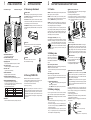
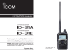
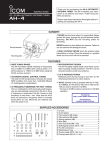
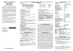
IMPORTANT
READ ALL INSTRUCTIONS carefully and completely before
using the transceiver.
SAVE THIS INSTRUCTION MANUAL. This manual contains
important safety and operating instructions for the IC-F4TR.
EXPLICIT DEFINITIONS
NEVER allow the antenna to come close to, or touch,
exposed body parts, especially the face or eyes while transmitting.
NEVER disassemble the transceiver. incorrect reassemble
may result in a fire hazard or electric shock.
NEVER operate the transceiver near unshielded electrical
TABLE OF CONTENTS
IMPORTANT
EXPLICIT DEFINITIONS
TABLE OF CONTENTS
SUPPLIED ACCESSORIES
1 PANEL DESCRIPTION
2 GETTING STARTED
2-1 Accessory attachment . . . . . . . . . . . . . . . . . . . . 2-1
2-2 Turning POWER ON . . . . . . . . . . . . . . . . . . . . .2-2
3 BATTERY PACKS AND BATTERY CASE
3-1 Caution . . . . . . . . . . . . . . . . . . . . . . . . . . . . . . .3-1
3-2 Battery case . . . . . . . . . . . . . . . . . . . . . . . . . . . .3-2
3-3 Battery charging . . . . . . . . . . . . . . . . . . . . . . . . .3-3
4 SPECIFICATIONS AND OPTIONS
4-1 Specifications . . . . . . . . . . . . . . . . . . . . . . . . . . .4-1
4-2 Options . . . . . . . . . . . . . . . . . . . . . . . . . . . . . . .4-2
4
SPECIFICATIONS AND OPTIONS
4-1 Specifications
• GENERAL
Frequency coverage (MHz)
Mode
Usable temperature range
Dimensions (proj not incl.)
Weight (with BP-196)
• TRANSMITTER
Output power
: 400–430, 450–490, 480–512
: 16K0F3E (25 kHz)
11K0F3E (12.5 kHz)
: –30˚C to +60˚C; –22°F to +140°F
: 57(W)×140(H)×37 (D) mm
; 21⁄4(W)×51⁄2(H)×115⁄32(D) in
: 390 g; 13.8 oz
:4W
• RECEIVER
Sensitivity (12 dB SINAD)
: 0.3 µV
Intermodulation rejection ratio : 75 dB typ.
Spurious response rejection : 70 dB typ.
Adjacent channel selectivity : 70 dB typ. (25 kHz)
65 dB typ. (12.5 kHz)
: 500 mW (at 5% distortion with an 8 Ω
Audio output power
blasting caps or in an explosive area.
AVOID the use of chemical agents such as benzene or alcohol when cleaning—use a water-dampened cloth only.
For U.S.A. only
CAUTION: changes or modifications to this transceiver, not
expressly approved by icom inc., could void your authority to
operate this transceiver under fcc regulations.
load)
SUPPLIED ACCESSORIES
q
w
e
r
Battery pack (comes attached to the transceiver)
Flexible antenna
Belt clip
1922 A-REAR SHEET
4-2 Options
• HM-46/HM-54/HM-75A SPEAKER-MICROPHONES
Combination speaker-microphone that provides convenient operation while hanging the transceiver from your belt clip.
• BC-119 DESKTOP CHARGER + AD-81 CHARGER ADAPTER
Used for rapid charging of battery packs. Charging time: 1.5 to 2
hours. An AC adapter is supplied with the chargers (depending on
version).
• BC-121 MULTI-CHARGER + AD-81 CHARGER ADAPTER
+ BC-124 AC ADAPTER
Rapidly charges of up to 6 battery packs (six AD-81’s are required)
at once. Charging time: 1.5 to 2 hours.
• BC-133 DESKTOP CHARGER
Regularly charges battery pack with/without transceiver. The AC
adapter, BC-122, is additionally required. Charging time: approx. 15
hours
• BC-110A/D/V WALL CHARGER
Used for charging via a domestic AC wall socket.
•CP-12L CIGARETTE LIGHTER CABLE
Used for charging via a vehicle’s cigarette lighter socket (12 V).
•OPC-254L DC POWER CABLE
Used for charging with an external power supply.
•BP-194 BATTERY CASE
Takes eight (8) AA (R6) size batteries. External DC-jack on the
transceiver can be used to charge the Ni-Cd battery cells.
•SP-13 EARPHONE
Provides clear audio in noisy environments.
All stated specifications are subject to change without notice or
obligation.
A-5632D-1US
Printed in Japan
© 1999 Icom Inc.
6-9-16 Kamihigashi, Hirano-ku, Osaka 547-0002 Japan
This device complies with Part 15 of
the FCC Rules. Operation is subject to
the condition that this device does not
cause harmful interference.
iF4TR
UHF TRUNKED RADIO
INSTRUCTION MANUAL
Count on us!
1
PANEL DESCRIPTION
IC-F4TR with keypad
IC-F4TR without keypad
q
2
GETTING STARTED
e
BATTERY PACKS AND BATTERY CASE
2-1 Accessory attachment
3-1 Caution
D BATTERY PACK
Before attaching, or replacing the battery pack, the volume
control MUST be rotated fully counterclockwise, until a click is
heard, to turn the power OFF.
NEVER incinerate used battery packs or battery cells. Internal
battery gas may cause an explosion.
• TO ATTACH the battery pack to the transceiver, mate the
notched ends of the battery pack and the transceiver, and
push the battery pack until it clicks into place.
w
3
• TO REMOVE the battery pack from the transceiver, push
and hold the battery release downwards, then lift up the battery pack.
r
NEVER immerse the battery pack or the battery case in
water. If the battery pack or case becomes wet, be sure to
wipe it dry BEFORE attaching it to the transceiver.
NEVER short terminals of the battery pack or battery case.
Also, current may flow into nearby metal objects so be careful
when placing battery packs in handbags, etc.
D With the BC-119 or BC-121
The optional BC-119 and BC-121 provide rapid charging of
optional Ni-Cd battery pack/s.
The following are additionally required:
• Only one AD-81 for the BC-119; six AD-81s for the BC-121.
• An AC adapter (may be supplied with the BC-119 depending on
version; The optional AC adapter, BC-124, for the BC-121).
Turn power
OFF.
Turn power
OFF.
If your battery pack seems to have no capacity even after
being charged, completely discharge it by leaving the power
ON overnight. Then, fully charge the battery pack again. If the
battery pack still does not retain a charge (or very little), a
new battery pack must be purchased.
RGER
I-CHA
MULT
D Recycling information (U.S.A. only)
t
y
u
D BELT CLIP
Attach the belt clip to the transceiver as illustrated below.
i
Attach the belt-clip
Release the belt-clip
o
q ANTENNA CONNECTOR
Connects the supplied antenna.
w VOLUME CONTROL [VOL]
Turns power ON and adjusts the audio level.
e [SP]/[MIC] JACK
Connect optional speaker-microphone, or headset.
3-2 Battery case
D ANTENNA
The antenna screws onto the transceiver as illustrated as at right.
t ACTIVITY LED
Lights red while transmitting.
u CHANNEL UP/DOWN KEYS [Y]/[Z]
Push either switch to change the operating channel.
i DEALER PROGRAMMABLE KEYS
[P0]/[P1]/[P2]/[P3]/[A]*/[B]*/[C]*/[D]*/[Ω]*/[–]
Can each be programmed for one of several functions by
your Icom dealer or system operator.
D Programmable key reference.
[–]
[P0]
[P1]
[P2]
[P3]
[Ω]*
[A]*
[B]*
[C]*
[D]*
*10-keypad type only.
o KEYPAD
Used to enter DTMF codes, the operating channel, etc.
When using the optional BP-194
attached to the transceiver, install 8 AA (R6) size Alkaline or
Ni-Cd batteries as illustrated as
at right.
When installing Ni-Cd batteries:
• Make sure all cells are the same brand, type and capacity.
• Never mix old and new batteries.
Either of the above may cause a fire hazard or damage the
transceiver.
r PTT SWITCH [PTT]
Transmits during push; receives during release.
y FUNCTION DISPLAY
Displays the preset user information.
The product that you have purchased contains a rechargeable battery. The battery is recyclable. At the end of its life,
under various state and local laws, it may be illegal to dispose of this battery into the municipal
waste stream. Call 1-800-822-8837 for battery
recycling options in your area or contact your
dealer.
2-2 Turning POWER ON
Rotate the volume control to the 12 o’clock position.
• A power-up alert tone sounds for about 2 sec. and an opening message may appear. (Depend on pre-setting.)
• Then the LCD shows user information.
(depending on pre-setting).
NOTE: If the power-up alert tone does not sound or a
channel number does not appear on the display, turn the
transceiver OFF, check the battery, then turn the transceiver back ON. If the power-up tone still does not sound
or a channel number does not appear, charge the battery
or replace it.
When installing dry or alkaline cells:
• Never connect DC power to the transceiver. Such a connection always charges the installed batteries and will damage the transceiver.
D LOW BATTERY INDICATION
- When
appears, battery capacity is becoming low and
transmitting is impossible.
- When
flashes, battery capacity is nearly exhausted.
3-3 Battery charging
Prior to using the transceiver for the first time, the battery
pack must be fully charged for optimum life and operation.
CAUTION: To avoid damage to the transceiver, turn it OFF
while charging.
• Recommended temperature range for charging: +10°C to
+40°C (+50°F to +104°F)
• Use the Icom’s charger (BC-119/BC-121 for rapid charging, BC110, and BC-133 for regular charging) only. NEVER use another
manufacturers’ chargers.
• An optional cable OPC-254L (for 13.8 V power source) or CP12L (for 12 V cigarette lighter socket) can be used in-stead of
the AC adapters of the supplied charger.
BC-121 + AD-81 (6 pcs.)
BC-119 + AD-81
AC adapter, BC-124
(purchased separately)
When using the BC-119 in the vehicle: If the charge indicator flashes orange, the vehicle battery voltage is low
and charging may not be performed. Check the vehicle
battery voltage in this case. If the charge indicator flashes
red, there may be a problem with the battery pack (or
charger). Re-insert the battery pack or contact your dealer.
D With the BC-133
The optional BC-133 provides regular
charging of optional Ni-Cd battery pack
with/without transceiver.
The following are additionally required:
• The optional AC adapter, BC-122.
D With the BC-110 or an optional cables
CAUTION: Only Ni-Cd batteries can be charged. NEVER
connect a wall charger when dry or Alkaline cells are installed in the BP-194 BATTERY CASE— the transceiver and/or
battery case may be damaged.
CAUTION: Even if the power source has enough capacity, the [CHARGE] jack can be used for charging purposes
only. You can not operate the transceiver without an internal power source.
Connect the optional BC-110, CP-12L or OPC-254L to the
[CHARGE] jack on the transceiver as illustrated below. Be
careful of battery overcharging as the connected battery is
charged simultaneously..
• Approx. charging period: 15 hrs.
• DO NOT turn power ON while connecting the BC-110A/D/V.
Current capacity is insufficient.
• AVOID over charging. The charging period should be less
than 48 hours.
BC-110A/D/V
(to AC outlet)
To
[CHARGE]
CP-12L
(to 12–16 V DC power source)
white
black
OPC-254L
(to 12–16 V DC power source)