1
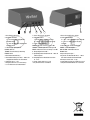
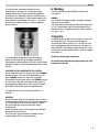
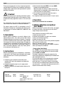
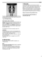
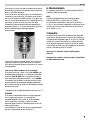
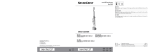
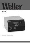
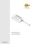
WTS A
Betriebsanleitung - Operating Instructions - Manual de uso
Inhaltsverzeichnis
Seite
1. Achtung!
2. Beschreibung
Technische Daten
3. Inbetriebnahme
4. Betrieb
5. OFFSET Schrauberkalibrierung
6. Wartung
7. Garantie
Table of contents
1
1
1
1
1
1
2
2
Page
1. Caution!
2. Description
Technical data
3. Instructions
4. Operation
5. OFFSET calibration screwdriver
6. Maintenance
7. Warranty
Índice
3
3
3
3
3
3
4
4
Página
1. ¡Atención!
2. Descripción
Datos técnicos
3. Puesta en servicio
4. Funcionamiento
5. Calibración de la compensación del destornillador
6. Mantenimiento
7. Garantía
5
5
5
5
5
5
6
6
1
2
1. Anschlussbuchse 8 Pin
2. High/Low Schalter*
L = 0%to 30% des angegebenen
Drehmomentes
H = 20% to 100% des angegebenen
Drehmomentes
3. LED Anzeige: grün/gelb/rot
POWER: Gerät an
TORQUE: Verschraubung in Ordnung
ERROR: Fehler
4. Drehmomenteinstellung *
5. Drehzahleinstellung von 40% - 100% des
angegebenen Wertes des Schraubers.
6. Softstart von 0 - 2 sec.
7. Hauptschalter mit 3,15 A Sicherung
* nur für ECL-Serie Schraubendreher
3
4
5
6
1. Screw driver 8 pin connector
2. High/Low Switch *
L = 0%to 30% of the torque range
H = 20% to 100% of the torque range
3. Lights: green/yellow/red
POWER: indicates that the system is OK
TORQUE: indicates that the screwing is OK
ERROR: indicates that the screwing is not OK
4. Torque Adjustment Knob *
5. Speed Adjustment Knob from 40 - 100% of
nominal speed
6. Ramp Adjustment Knob Soft start from
0 - 2 sec.
7. Power supply with fuse 3,15 A
* only for ECL-Series screwdriver
7
1. Base de conexión de 8 clavijas
2. Interruptor Alto/Bajo*
B = 0 % a 30 % del par de giro indicado
A = 20 % al 100 % del par de giro
indicado
3. Indicador LED: verde/amarillo/rojo
POWER: unidad encendida
PAR DE GIRO: atornillado correcto
ERROR: Fallo
4. Ajuste del par de giro *
5. Ajuste de la velocidad del 40 % - 100 %
del valor indicado del destornillador.
6. Arranque suave de 0 - 2 seg.
7. Interruptor principal con fusible de 3,15 A
* solo para destornilladores de la serie ECL
Deutsch
Wir danken Ihnen für das Vertrauen, dass sie mit dem Kauf des
Weller WTS A Steuergerät in unser Unternehmen gesetzt
haben.
Bei
der
Fertigung
wurden
strengste
Qualitätsanforderungen zugrunde gelegt, die eine einwandfreie
Funktion des Gerätes garantieren.
1. Achtung!
Lesen Sie diese Betriebsanleitung und die beigelegten
Sicherheitshinweise aufmerksam durch. Bei Nichtbeachtung
der Sicherheitsvorschriften droht Gefahr für Leib und Leben.
Für andere, von der Betriebsanleitung abweichende
Verwendung, sowie bei eigenmächtiger Veränderung, wird
von Seiten des Herstellers keine Haftung übernommen.
Das elektrische Steuergerät WTS A entspricht der EGKonformitätserklärung in Übereinstimmung mit den grundlegenden Sicherheitsanforderungen der Richtlinien
2006/42/EG, 2006/95/EG und 2004/108/EG.
b) Stecken Sie den Controllerstecker in eine Netzsteckdose
90 / 260 V- 50 / 60 Hz.
c) Schalten Sie den Controller am schwarzen Knopf auf der
Rückseite ein.
d) Wählen Sie die gewünschte Drehzahl (SPEED) und den
gewünschten Anlauf (RAMP) über die entsprechenden
Knöpfe aus Stellen Sie das Drehmoment ein. Stellen Sie
sicher, dass die gewählten Werte kompatibel mit dem eingestellten Drehmomentwert sind, so dass die Kupplung
korrekt eingreifen kann.
e) Schieben Sie nicht den Vorwärts-/Rückwärts-Schalter,
während der Motor läuft; der Motor könnte beschädigt
werden!
Überschreiten Sie für eine lange Lebensdauer des Motors
nicht 60° C, wenn er in Betrieb ist.
4. Betrieb
Siehe Handbuch des Elektronischen Schraubers.
5. Offset Schrauberkalibrierung
(nur ECL- Modelle)
2. Beschreibung
Das WELLER Steuergerät wird zum Festziehen mit dem entsprechenden Drehmoment von Schrauben, Muttern,
Gewindebolzen und anderen Arten von Anschlüssen mit
Gewinden in jedem Material verwendet. Selbstverständlich
können die Schrauber mit Schrauben mit einem größeren
Durchmesser verwendet werden, sofern der Drehmoment in
den angegebenen Bereich fällt. Alle Modelle verfügen über
einen Linkslauf und können demzufolge zum Lösen von
Verschraubungen verwendet werden. Elektroschrauber werden hauptsächlich in der Elektronikindustrie sowie für elektrische Anwendungen, Verkabelungen, Spielzeuge, Lampen,
Brillen, sowie in der Leichtmechanikindustrie usw.
verwendet.
3. Inbetriebnahme
Das WELLER Schraubersystem besteht aus einem Schrauber,
einem Kabel mit 2 8-poligen x M12-Buchsen, einer
Stromversorgung und einem Steuergerät. Befolgen Sie zur
Installation bitte die folgenden Anweisungen.
a) Schließen Sie die 8-poligen Anschlüsse des Kabels am
WTS-Controller und am Schrauber an und ziehen Sie die
entsprechenden Muttern fest.
Wird der Schrauber zum ersten Mal verwendet, sollten Sie
den Offset im Steuergerät kalibrieren, so dass der volle
Drehmomentbereich erreicht werden kann.
Bitte befolgen Sie die Anleitung der WTS-Station
a) Schalten Sie das Steuergerät aus
b) Schließen Sie den Schrauber so an, dass er im
Uhrzeigersinn läuft
c) Drücken Sie den Startschieber und halten Sie ihn fest
d) Schalten Sie das Steuergerät ein
Nach 5 Sekunden beginnen die Motoren bis zum Ende des
Offsetzyklus mit unterschiedlichen Drehzahlen.
Wiederholen Sie dieses Vorgehen sowohl im L- als auch im
H -Bereich.
Tun Sie dies einmal; eine Wiederholung ist nicht notwendig,
bis Sie den Schrauber wechseln.
- Drehmomenteinstellung Kupplungsmodell:
Der "TORQUE"-Knopf und der H/L-Drehmomentschalter
haben keine Funktion mehr und der Benutzer kann am
Steuergerät lediglich RAMP und SPEED einstellen.
Das Drehmoment wird durch Änderung der Kompression
der Kupplungsfeder, Festziehen oder Lösen des
Gewinderings nach Lösen der Sicherungsmutter eingestellt.
Technische Daten
Bestellnummer
T0053901699
1
Modell
WTS A
Funktionen
Eingang: 90/260 VAC
50/60 HZ
Ausgang: 40 VDC 120 VA max
Sicherung: 3,15 A
Abmessungen mm
190 x 170 x 105
Gewicht
1,7 kg
Deutsch
Zur Erhöhung des Drehmoments drehen Sie den
Gewindering im Uhrzeigersinn; zur Verringerung des
Drehmoments drehen Sie den Gewindering gegen den
Uhrzeigersinn. Am Kupplungsring gibt es eine Skala zum
Ablesen des Drehmoments, sie bietet jedoch lediglich eine
grobe Übersicht (die Kupplung kann auch 2 - 3 mm unter
dem Minimum arbeiten, wichtig ist, dass die Kupplung
korrekt eingreift.)
6. Wartung
Das WTS-Steuergerät und die WBTS-Schrauber sind
wartungsfrei
HINWEIS
Der von WELLER Elektroschraubern erzeugte Schallpegel
liegt immer unter 55dB(A).
Die an den Benutzer übertragenen Vibrationen liegen unter
2,5 m/s². Insbesondere liegt die Vibrationsexposition für
Bediener, die bis zu 4200 Schraubzyklen täglich durchführen, unter 1 m/s².
7.Garantie
Die Mängelansprüche des Käufers verjähren in einem Jahr
ab Ablieferung an ihn. Dies gilt nicht für Rückgriffsansprüche des Käufers nach §§ 478, 479 BGB. Aus einer
von uns abgegebenen Garantie haften wir nur, wenn die
Beschaffenheits- oder Haltbarkeitsgarantie von uns schriftlich und unter Verwendung des Begriffs „Garantie“ abgegeben worden ist.
Technische Änderungen vorbehalten!
Zur Sicherung des eingestellten Drehmomentwertes
können Sie den Feststellring verwenden bzw. durch
Entfernung des Stahlrings können Sie eine Einstellschraube
befestigen, wobei Sie auf die entsprechenden Rillen achten
müssen.
Die aktualisierten Betriebsanleitungen finden Sie unter
www.weller-tools.com
LEUCHTEN AUF DER VORDERSEITE DER STATION:
Auf der Vorderseite gibt es 3 Leuchten: die grüne (POWER)
leuchtet konstant, wenn das Gerät eingeschaltet ist; die
gelbe (TORQUE) leuchtet nur, wenn das eingestellte
Drehmoment erreicht wurde, und die rote (ERROR) leuchtet
nur, wenn das eingestellte Drehmoment nicht korrekt ist
(Schraubvorgang abgeschlossen oder Drehzahl während
ANLAUFZEIT erreicht oder Verlust der Motorkontrolle).
Die Temperatur des Geräts kann normalerweise 45 °C
erreichen.
ACHTUNG:
Auf der Rückseite findet sich ein Anschluss, der mit einem
Sicherungsträger und einem Ein-/Aus-Schalter ausgestattet
ist. Für den Austausch der Sicherung ziehen Sie einfach
den Sicherungsträger heraus und tauschen Sie die
Sicherung aus.
Achten Sie immer darauf, das Steuergerät am Ende jeder
Arbeitsschicht auszuschalten.
Zum Testen des Drehmomentwerts empfehlen wir die
Verwendung des WTT 5 Drehmomenttesters.
2
English
Thank you for placing your trust in our company by purchasing the Weller WTS A control unit. Production was based on
stringent quality requirements which guarantee the perfect
operation of the device.
1.Caution!
Please read carefully these Operating Instructions and the
attached safety information prior to initial operation. Failure
to observe the safety regulations results in a risk of life and
limb.
d) Select the desired speed (SPEED) and ramp (RAMP)
through the corresponding knobs.
Adjust the torque (see section 3). Make sure that the
selected values are compatible with the torque value set
so that the clutch can shoot properly.
e) Do not slide the forward/reverse while the motor is
running, it’s dangerous for the motor!
For a long life of motor not pass over 60 °C when it works.
4. Operation
Please refer to manual of the screwdriver.
The manufacturer shall not be liable for damage resulting
from misuse of the machine or unauthorised alterations.
The electric control unit WTS A corresponds to the EC
Declaration of Conformity in accordance with the basic safety requirements of Directives 2006/42/CE, 2006/95/CE and
2004/108/CE.
2. Description
WELLER electric screwdrivers are used to tighten to the
required torque screws, nuts, studs and any other kind of
threaded connection on any material. Obviously, it is possible
to use the screwdrivers with screw having a larger diameter
if the torque falls within the indicated range. All models are
reversible and can consequently be used to unscrew. Electric
screwdrivers are mainly used in the electronic industry as
well as for electric appliances, wiring, toys, lamps, glasses,
in the mechanical light industry etc.
3. Instructions
WELLER screwdriving system is composed by a screwdriver,
a cable with 2 x M12 female 8 pin connectors and a power
supply and control unit. To install it please follow the
instructions.
a) Connect the 8-pin connectors of the cable to the
controller WTS and to the screwdriver and tighten the
relevant nuts.
b) Connect the controller plug to a main supply socket
90/260 V- 50/60 Hz.
c) Switch the controller on through the black button on the
back panel.
5. Offset calibration screwdriver
(ECL Model)
When the screwdriver is used for the first time, we suggest
to calibrate the offset in the control unit so that the full
range of torque may be achieved.
Please follow the instructions of WTS station
a) Switch the control unit OFF
b) Connect the screwdriver in order to run clockwise
c) Push start and keep on pushing
d) Switch the control unit ON
After 5 secs, the motor will start running at different speeds
until the end of the offset cycle.
Repeat this procedure either in L and H range.
Do this once; it will not be necessary to repeat it anymore,
unless you change the screwdriver.
- Torque setting Clutch Model:
The "TORQUE" knob and the H/L torque switch no longer
have any function and the operator can set on the control
unit only RAMP and SPEED.
The torque is adjusted by varying the compression the
clutch spring, tightening or untightening the threaded collar
after loosening the lock nut.
To increase the torque, turn the threaded collar clockwise.
To decrease the torque, turn counterclockwise. On the
clutch ring there is a scale label to help to set the torque.
The value must be considered merely indicative (the clutch
may also work 2 - 3 mm below the minimum level, but it is
important that the clutch shots correctly.)
Technical Data
Order-No.
T0053901699
3
Model
WTS A
Features
Dimensions mm
Input: 90/260 V AC
190 x 170 x 105
50/60 HZ
Output: 40 VDC 120 VA max
Fuse: 3,15 A
Weight
1,7 kg
English
7. Warranty
Claims based on defects will fall under the statute of
limitations 12 months after delivery to the purchaser of the
goods. This shall not apply to rights of recourse of the
purchaser according to sections 478, 479 German Civil
Code. We shall assume liability for warranties supplied by
us only if the quality guarantee or service warranty has
been submitted in writing and using the term "Warranty".
Subject to technical change without notice!
See the updated operating instructions at
www.weller-tools.com.
To set the torque, screw or unscrew the lock nut. Then the
removing steel ring can be fixed by a grain* taking care of
it in the appropriate grooves.
* grain not included in delivery
FRONT PANEL LIGHTS AT STATION:
On the front panel you can also see 3 lights: the green one
(POWER) will light permanently when the power is on; the
yellow one (TORQUE) will light only when the torque has
been reached and the red one (ERROR) will light only when
the torque is not correct (screw closed or torque reached
during the RAMP time).
The temperature of the unit can normally reach 45°C.
ATTENTION :
On the back panel you can find a socket equipped with a
fuse holder and on/off switch. To replace the fuse just pull
out the fuse holder and change the fuse.
Always remember to switch off the control unit at the end
of each working shift.
To check the torque value we suggest the use of WTT5
torque tester.
6. Maintenance
The WTS control unit and the WBTS screwdrivers are
maintenance free
NOTE
The sound level generated by WELLER electric screwdrivers
is always lower than 55 dB(A).
The vibrations transmitted to operator’s hand are lower
than 2.5 m/s². In particular the exposition to vibrations is
lower than 1 m/s² for operators who make up to 4200
screwing cycles per day.
4
Español
Gracias por depositar su confianza en nuestra empresa al
adquirir la unidad de control WTS A Weller. La fabricación de
este aparato está sometida a los más rigurosos controles de
calidad para garantizar un perfecto funcionamiento del
mismo.
1. ¡Atención!
Lea detenidamente este manual de instrucciones y la
información de seguridad adjunta. Si no se cumplen las
instrucciones de seguridad prescritas, corre el riesgo de
sufrir lesiones graves e incluso peligro de muerte.
El fabricante no asume ninguna responsabilidad por una
utilización diferente a la descrita en el manual de
instrucciones ni tampoco en caso de realizar
modificaciones arbitrarias.
La unidad de control eléctrica WTS A dispone de la
Declaración de Conformidad CE que certifica el
cumplimiento de los requisitos básicos de seguridad
contemplados en las Directivas 2006/42/CE,
2006/95/CE y 2004/108/CE.
2. Descripción
La unidad de control WELLER se usa para apretar tornillos,
tuercas, espárragos y cualquier tipo de conexión roscada al
par de giro necesario sobre cualquier material.
Evidentemente, es posible usar los destornilladores con
tornillos de un diámetro más grande si el par de giro está
dentro del rango indicado. Todos los modelos disponen de
giro reversible y, por consiguiente, se pueden usar para
destornillar. Los destornilladores eléctricos se usan
principalmente en la industria electrónica, así como en los
aparatos eléctricos, cableados, juguetes, lámparas, gafas, en
la industria mecánica ligera,
etc.
3. Puesta en servicio
El sistema de destornillado WELLER consta de un
destornillador, un cable con 2 casquillos x M12 de 8 polos,
una fuente de alimentación y una unidad de control.
Para instalarlo siga las instrucciones.
a) Conecte los conectores de 8 polos del cable al
controlador WTS y al destornillador y apriete las tuercas
pertinentes.
b) Conecte el enchufe del controlador a una toma de
suministro de corriente de 90/260 V - 50/60 Hz.
c) Encienda el controlador mediante el botón negro situado
en la parte trasera del panel.
d) Seleccione la velocidad de giro (VELOCIDAD) y el
arranque (RAMPA) deseadas mediante los botones
correspondientes, ajuste el par de giro. Asegúrese de que
los valores seleccionados son compatibles con el valor del
par de giro ajustado para que el embrague pueda
engranar correctamente.
e) No deslice el interruptor de adelante/atrás mientras el
motor está en marcha, se podría dañar el motor.
Para mantener una larga vida útil del motor, no sobrepase los
60 °C durante el funcionamiento.
4. Funcionamiento
Consulte el manual del destornillador eléctrico.
5. Calibración de la compensación
del destornillador
(solo modelos ECL)
Cuando use el destornillador por primera vez, le
recomendamos que calibre la compensación en la unidad
de control para alcanzar la totalidad del rango del par de
giro.
Siga las instrucciones de la estación WTS
a) Apague la unidad de control
b) Conecte el destornillador para que funcione en el sentido
de las agujas del reloj
c) Pulse el interruptor de inicio y manténgalo pulsado
d) Encienda la unidad de control
Tras 5 segundos, los motores empezarán a funcionar a
diferentes velocidades hasta el final del ciclo de
compensación.
Repita este procedimiento tanto en el rango B como en el A.
Efectúelo una sola vez, ya no será necesario volver a repetir
este procedimiento hasta que cambie el destornillador.
- Ajuste del par de giro en el modelo con embrague:
El botón "PAR DE GIRO" y el interruptor de par de giro A/B
ya no tienen función y el operario solo puede ajustar
RAMPA y VELOCIDAD en la unidad de control.
Datos técnicos
Referencia
T0053901699
5
Modelo
WTS A
Funciones
Entrada: 90/260 V CA
50/60 HZ
Salida: 40 V CC 120 VA máx
Fusible: 3,15 A
Dimensiones mm
190 x 170 x 105
Peso
1,7 kg
Español
El par de giro se ajusta variando la compresión del muelle
del embrague, apretando o aflojando el anillo roscado tras
aflojar la tuerca de seguridad.
Para incrementar el par de giro, gire el anillo roscado en el
sentido de las agujas del reloj. Para reducir el par de giro,
gire el anillo roscado en sentido contrario a las agujas del
reloj. En el anillo del embrague hay una etiqueta de escala
para ayudar a ajustar el par de giro. Este valor debe
considerarse como meramente indicativo (puede que el
embrague funcione 2 - 3 mm por debajo del nivel mínimo,
pero es importante que el embrague engrane
correctamente).
6. Mantenimiento
La unidad de control WTS y los destornilladores WBTS no
requieren ningún mantenimiento
NOTA
El nivel de sonido generado por los destornilladores
eléctricos WELLER es siempre inferior a 55 dB(A).
Las vibraciones transmitidas al operario son inferiores a
2,5 m/s². Particularmente la exposición a vibraciones de los
usuarios que realizan hasta 4.200 ciclos de atornillado al
día es inferior a 1 m/s².
7.Garantía
Los derechos de reclamación por defectos del comprador
prescriben un año después de la compra. Solo válido para
los derechos del comprador según el art. §§ 478, 479 BGB
(código civil alemán). Únicamente nos responsabilizamos
de los derechos de garantía cuando la garantía de compra
y vida útil del aparato haya sido entregada por nosotros por
escrito y utilizando el término "Garantía".
¡Reservado el derecho a realizar modificaciones
técnicas!
Encontará los manuales de instrucciones actualizados
en www.weller-tools.com.
Para fijar el par de giro ajustado puede usar la tuerca de
seguridad o apretar una tuerca de ajuste tras extraer el
anillo de acero, procurando que ésta encaje en las ranuras
correspondientes.
LUCES EN EL PANEL FRONTAL DE LA ESTACIÓN:
En el panel frontal hay 3 luces: la luz verde (POWER) está
encendida permanentemente si la unidad está encendida;
la amarilla (PAR DE GIRO) solo se encenderá cuando se
haya alcanzado el par de giro ajustado, y la roja (ERROR)
se encenderá solo cuando el par de giro ajustado no sea
correcto (proceso de atornillado finalizado, velocidad de
giro alcanzada durante el TIEMPO DE ARRANQUE o pérdida
del control del motor).
La temperatura de la unidad normalmente alcanza los 45 °C.
ATENCIÓN:
En el panel trasero puede encontrar una toma equipada
con un soporte para fusible y un interruptor de
encendido/apagado. Para sustituir el fusible solo debe
extraer el soporte para fusible y cambiar el fusible.
Recuerde apagar siempre la unidad de control al final de
cada turno de trabajo.
Para comprobar el valor del par de giro le recomendamos
que use el comprobador de par de giro WTT 5.
6
G E R M A N Y
Weller Tools GmbH
Carl-Benz-Str. 2
74354 Besigheim
Phone: +49 (0) 7143 580-0
Fax: +49 (0) 7143) 580-108
G R E A T B R I T A I N
Apex Tool Group
(UK Operations) Ltd
4th Floor Pennine House
Washington, Tyne & Wear
NE37 1LY
Phone: +44 (0191) 419 7700
Fax: +44 (0191) 417 9421
I T A L Y
Apex Tool S.r.I.
Viale Europa 80
20090 Cusago (MI)
Phone: +39 (02) 9033101
Fax: +39 (02) 90394231
S W I T Z E R L A N D
Apex Tool Switzerland Sàrl
Rue de la Roselière 8
1400 Yverdon-les-Bains
Phone: +41 (024) 426 12 06
Fax: +41 (024) 425 09 77
A U S T R A L I A
Apex Tools
P.O. Box 366
519 Nurigong Street
Albury, N. S. W. 2640
Phone: +61 (2) 6058-0300
Fax: +61 (2) 6021-7403
CANADA
Apex Tools - Canada
164 Innnisfil street
Barrie Ontario
Canada L4N 3E7
Phone: +1 (705) 728 5564
Fax: +1 (705) 728 3406
F R A N C E
Apex Tool Group S.A.S.
25 Avenue Maurice Chevalier BP 46
77832 Ozoir-la-Ferrière, Cedex
Phone:+33 (0) 160.18.55.40
Fax: +33 (0) 164.40.33.05
C H I N A
Apex Tools
18th Floor, Yu An Building
738 Dongfang Road
Pudong, Shanghai
200122 China
Phone: +86 (21) 5111-8300
Fax: +86 (21) 5111-8446
U S A
Apex Tool Group, LLC.
14600 York Rd. Suite A
Sparks, MD 21152
Phone: +1 (800) 688-8949
Fax: +1 (800) 234-0472
www.weller-tools.com
Weller® is a registered Trademark and registered Design of Apex Tool Group, LLC.
© 2011, Apex Tool Group, LLC.
T005 57 226 00 / 08.2011