1
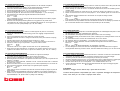
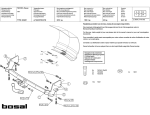
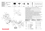
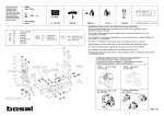
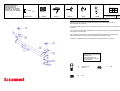
Montagehandleiding
Fitting instruction
Montageanleitung
Description de montage
Istruzioni di montaggio
Instrucciones de montaje
SUZUKI Vitara
7/1988 -
TYPE: 016172
NL
D
I
F
GB
E
EC 94/20
e4
00-0974
1450 kg
1500 kg
50 kg
7,23 kN
(c) BOSAL 08-03-2005
Rev. nr. 01
Raadpleeg uw dealer voor de max. massa die uw wagen mag trekken.
Die maximale Anhängelast ihres Fahrzeuges können Sie im Fahrzeugschein oder im
Benutzerhandbuch nachlesen.
For the max. trailer weight of your car please refer to the owner's manual or your car homologation
documents.
Pour connaître le poids maxi remorquable pour votre voiture consulter la notice d'utilisation de
votre voiture ou la carte grise.
Per conoscere il peso massimo rimorchiabile dalla propria autovettura, fare riferimento al
manuale d'istruzione od ai documenti di omologazione della vettura stessa.
Consulte a su distribuidor sobre el peso máximo que puede remolcar su vehículo.
Meegeleverde onderdelen
Mitgelieferte Befestigungsteile
Provided parts
Materiel de fixation joint
Componenti forniti a corredo
Piezas incluidas
4x
2x
M12x1,25x35
M12x110
6x
M12
4x
M12
016172 MONTAGEHANDLEIDING
1. Meegeleverde onderdelen en bevestigingsmaterialen van de trekhaak verwijderen.
Eventueel aanwezige kit ter plaatse van de bevestigingspunten verwijderen.
2. Demonteer de demontabele sleepogen (deze komen te vervallen).
3. Monteer de trekhaak bij de gaten “A” m.b.v. de bouten M12x1,25x35 (veer- en sluitringen!).
4. Boor de bestaande gaten t.p.v. “B” door de chassisbalk op ca. ø 13mm.
5. Monteer bij de gaten “B” de bouten M12x110 met contraplaatjes “1” ( incl. veerringen).
6. Zet de trekhaak vast. Hierbij de volgende aanhaalmomenten hanteren:
M12x1,25 87 Nm
M12
79 Nm.
Het is noodzakelijk om na ca. 1000 km gebruik de boutverbindingen na te trekken (volgens
gegeven aanhaalmomenten).
7. Bosal kan niet aansprakelijk worden gesteld voor enig gebrek in het produkt zoals
veroorzaakt door de schuld of door welk onoordeelkundig gebruik ook van de gebruiker of
een persoon voor wie hij aansprakelijk is (art. 185, lid 2 N.B.W.).
016172 DESCRIPTION DE MONTAGE
1. Séparer les différents éléments d’attelage. Enlever le mastic de protection autour des points de fixation.
2. Démonter les anneaux de remorquage amovible (ils ne seront pas remontés).
3. Monter l’attelage au niveau des trous “A” à l’aide des boulons M12x1,25x35, des rondelles grower et des
rondelles plates.
4. Percer les trous existants au niveau des trous “B” à travers du longeron du châssis au ± ø 13mm.
5. Monter les boulons M12x110 avec les contre-plaques “1” et les rondelles grower au niveau des trous
“B”.
6. Fixer l’attelage. Bloquer l’ensemble de la boulonnerie aux couples de serrage suivants:
M12x1,25
87 Nm
M12
79 Nm.
Il est conseillé de vérifier le serrage de toute la boulonnerie aprés 1000 Km de traction.
7. Bosal décline toute responsabilité concernant des défauts éventuels de cet attelage qui seraient causés
par une mauvaise utilisation. Seul l’utilisateur est responsable (art 185 lid 2 NBW).
016172 FITTING INSTRUCTIONS
1. Unpack the towing bracket and check it’s contents against the parts list. If necessary,
remove the underseal from around the fitting points of the luggage compartment/frame
members.
2. Remove the detachable towing rings (these will no longer be used).
3. Mount the towbar at the holes “A” using the bolts M12x1,25x35, plain washers and spring
washers.
4. Drill the existing holes at “B” through the frame member to ± ø 13mm.
5. Mount the bolts M12x110 with backing plates “1” (with spring wahsers) at the holes “B”.
6. Secure the towbar using a torque-wrench. Torque the bolts as follows:
M12x1,25
87 Nm
M12
79 Nm.
After about 1000 km use, re-tighten the bolts and nuts to the specified torque.
7. Bosal cannot be held responsible for any defects in the product caused by fault or by any
injudicious use whatever of the user or a person he is liable for. (sect. 185, art. 2 N.B.W.)
016172 ANBAUANWEISUNG
1. Die Anhängevorrichtung auspacken und die Befestigungsteile auf Vollständigkeit überprüfen. Im Bereich
der Befestigungspunkte den Unterbodenschutz entfernen.
2. Die abnehmbaren Abschleppösen demontieren (diese werden nicht mehr benötigt).
3. Die Anhängevorrichtung mit Schrauben M12x1,25x35, Federringen und Unterlegscheiben an die Löcher
“A” montieren.
4. Die vorhandenen Löcher “B” durch den Chassisrahmen auf ø 13mm bohren.
5. Die Schrauben M12x110, Gegenplatten “1” und Federringen an die Löcher “B” montieren.
6. Die Anhängevorrichtung ausrichten und alle Schrauben mit folgenden Drehmomenten anziehen:
M12x1,25
87 Nm
M12
79 Nm.
Nach ca. 1000 km die Bolzenverbindungen, wie angegeben, nachziehen.
7. Für einen Mangel am Produkt, der durch den Fahrzeughalter oder eine andere Person aufgrund
unsachgemäßer Benutzung verursacht wurde, übernimmt Bosal keine Haftung. (art. 185 lid 2 N.B.W.)
016172 INSTRUCCIONES DE MONTAJE
1. Sacar las piezas y el material de sujección incluidos en el gancho de remolque.
Si procede, retirar el pegamento existente en los puntos de sujección.
2. Retirar los pernos originales del chasis (Estos no volverán a emplearse).
3. Montar el gancho en los orificios “A” empleando los tornillos M12 x 1,25 x 35, incluyendo los aros
elásticos y arandelas.
4. Ensanchar los orificios existentes, marcados como “B” a través del chasis hasta un diámetro
de 13mm (más o menos).
5. Montar los tornillos M12x110 con la placas (con los muelles separadores) en los orificios “B”.
6. Fijar el gancho de remolque. Atenerse aquí a los siguientes pares de apriete:
M12x1,25
87 Nm
M12
79 Nm
Cada 1000 km de uso es necesario comprobar las conexiones del perno (según los pares de
apriete dados).
7. Bosal no asume responsabilidad de ningún tipo por defectos en el producto causados por o
debidos a un uso imprudente, tanto por parte del usuario como de cualquier persona bajo su
responsabilidad (art. 185, párrafo 2 N.B.W. (Código Civil Holandés)).
016172 ISTRUZIONI DI MONTAGGIO
1. Aprire la confezione d’imballaggio della struttura di traino e controllare il contenuto a fronte dell’elenco
componenti. Se necessario, rimuovere il mastice di protezione intorno ai punti di fissaggio.
2. Smontare gli anelli amovibili di traino di emergenza (non saranno più rimontati).
3. Montare il dispositivo di traino nei fori “A” con bulloni M12x1.25x35, rondelle elastiche e rondelle piane.
4. Forare i fori esistenti all’altezza dei fori “B” attraverso il longherone del telaio a diam. 13 mm.
5. Montare i bulloni M12x110 con le contropiastre “1” e le rondelle elastiche nei fori “B”.
6. Fissare il dispositivo di traino. Bloccare l’insieme della bulloneria alle coppie di serraggio seguenti:
M12x1.25 = 87 Nm
M12 = 79 Nm
ATTENZIONE:
Verificare il serraggio di tutti i bulloni dopo i primi 1000 Km di traino.
La Bosal declina qualsiasi responsabilità per errato o imperfetto montaggio del dispositivo di
traino, come anche per uso errato o improprio dello stesso.