1
BA_U1_86_01.fm Seite 0 Dienstag, 6. April 2004 9:40 09
STIH)
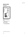
STIHL FS 55
Instruction Manual
Manual de instrucciones
Warning!
For safe operation follow all safety
precautions in Instruction Manual - improper
use can cause serious injury.
Advertencia!
Para su seguridad durante el manejo de este
producto, siga siempre las precauciones de
seguridad dadas en el manual de
instrucciones - el uso indebido puede causar
lesiones graves.
English / USA
© ANDREAS STIHL AG & Co. KG, 2007
0458 233 8621 C. M16. H7. CP. Printed in USA
Printed on chlorine-free paper.
Printing inks contain vegetable oils; paper can be recycled.
BA_SE_012_006_01_12.fm
Contents
Guide to Using this Manual .............. 2
Safety Precautions and
Working Techniques ......................... 3
Approved Combinations
of Mowing Tool, Deflector,
Handle and Harness ....................... 16
Mounting the Bike Handle .............. 18
Mounting the Loop Handle ............. 19
Fitting the Carrying Eye .................. 20
Mounting the Deflector ................... 21
Mounting the Cutting Tools ............. 21
Fuel ................................................ 26
Fueling ............................................ 27
Fitting the Harness ......................... 27
Balancing the Brushcutter .............. 28
Starting / Stopping .......................... 29
Operating Instructions .................... 33
Cleaning the Air Filter ..................... 33
Motor Management ........................ 34
Adjusting the Carburetor ................ 34
Checking the Spark Plug ................ 36
Rewind Starter ................................
Storing the Machine .......................
Lubricating the Gearbox .................
Sharpening
Metal Cutting Tools .........................
Inspections and Maintenance
by STIHL Service ...........................
Maintenance Chart .........................
Parts and Controls .........................
Specifications .................................
Special Accessories .......................
Maintenance and Repairs ..............
STIHL Incorporated
Federal Emission Control
Warranty Statement ........................
STIHL Incorporated California
Exhaust and Evaporative
Emissions Control
Warranty Statement ........................
Trademarks ....................................
37
37
37
38
39
40
41
43
44
45
46
48
50
Allow only persons who understand this
manual to operate your trimmer/
brushcutter.
To receive maximum performance and
satisfaction from your STIHL trimmer/
brushcutter, it is important that you read
and understand the maintenance and
safety precautions, starting on page 3,
before using your trimmer/brushcutter.
Contact your STIHL dealer or the STIHL
distributor for your area if you do not
understand any of the instructions in this
manual.
!Warning!
Because a trimmer/brushcutter is a highspeed cutting tool some special safety
precautions must be observed to reduce
the risk of personal injury.
Careless or improper use may cause
serious or even fatal injury. Make sure
your unit is equipped with the proper
deflector, handle and harness for the
type of cutting attachment being used.
Always wear proper eye protection.
STIHL's philosophy is to continually
improve all of its products. As a result,
engineering changes and improvements are made from time to time. If the
operating characteristics or the appearance of your trimmer/brushcutter differs
from those described in this manual,
please contact your STIHL dealer for
information and assistance.
STIHl
FS 55
1
English / USA
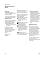
Guide to Using this Manual
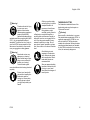
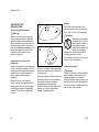
Pictograms
All the pictograms attached to the
machine are shown and explained in
this manual.
The operating and handling instructions
are supported by illustrations.
In addition to the operating instructions,
this manual may contain paragraphs
that require your special attention. Such
paragraphs are marked with the
symbols described below:
Symbols in text
Warning where there is a risk of an
accident or personal injury or
serious damage to property.
The individual steps or procedures
described in the manual may be marked
in different ways:
Caution where there is a risk of
damaging the machine or its
individual components.
:
Note or hint which is not essential
for using the machine, but may
improve the operator’s understanding of the situation and result
in better use of the machine.
A bullet marks a step or procedure
without direct reference to an
illustration.
A description of a step or procedure that
refers directly to an illustration may
contain item numbers that appear in the
illustration.
Example:
Loosen the screw (1)
Lever (2) ...
2
Note or hint on correct procedure in
order to avoid damage to the
environment.
Equipment and features
This instruction manual may refer to
several models with different
features. Components that are not
installed on all models and related
applications are marked with an
asterisk (*). Such components may
be available as special accessories
from your STIHL dealer.
Engineering improvements
STIHL’s philosophy is to continually
improve all of its products. As a result,
engineering changes and improvements
are made from time to time. If the
operating characteristics or the
appearance of your machine differ from
those described in this manual, please
contact your STIHL dealer for
assistance.
Therefore some changes, modifications
and improvements may not be covered
in this manual.
FS 55
English / USA
Safety Precautions and
Working Techniques
Warning!
Because a brushcutter is
a high-speed, fast-cutting
power tool, special safety
precautions must be
observed to reduce the risk of personal
injury.
It is important that you
read, fully understand and
observe the following
safety precautions and
warnings. Read the
owner's manual and the
safety instructions periodically. Careless
or improper use of any brushcutter may
cause serious or fatal injury.
Have your STIHL dealer show you how
to operate your brushcutter. Observe all
applicable local safety regulations,
standards and ordinances.
!Warning!
Do not lend or rent your brushcutter
without the owner's manual. Be sure that
anyone using your brushcutter
understands the information contained
in this manual.
FS 55
!Warning!
The use of any brushcutter may be
hazardous. If the rotating cutting tool
comes in contact with your body, it will
cut you. When it comes in contact with
solid foreign objects such as rocks or
bits of metal, it may fling them directly or
by ricochet in the direction of bystanders
or the operator.
Striking such objects could damage the
cutting attachment and may cause
blades to crack, chip or break.
STIHL does not recommend the use of
rigid blades when cutting in stony areas.
Thrown objects or damaged blades may
result in serious or fatal injury to the
operator or bystanders.
!Warning!
Minors should never be allowed to use a
brushcutter. Bystanders, especially
children, and animals should not be
allowed in the area where a brushcutter
is in use.
Never let the brushcutter run
unattended.
Most of these safety precautions and
warnings apply to the use of all STIHL
brushcutters. Different models may have
different parts and controls. See the
appropriate section of your owner's
manual for a description of the controls
and function of the parts of your model
brushcutter.
Safe use of a brushcutter involves
1.
the operator
2.
the brushcutter
3.
the use of the brushcutter.
THE OPERATOR
Physical Condition
You must be in good physical condition
and mental health and not under the
influence of any substance (drugs,
alcohol, etc.) which might impair vision,
dexterity or judgement. Do not operate a
brushcutter when you are fatigued.
Be alert – if you get tired while operating
your brushcutter, take a break.
Tiredness may result in loss of control.
Working with any brushcutter can be
strenuous. If you have any condition that
might be aggravated by strenuous work,
check with your doctor before operating
a brushcutter.
3
English / USA
!Warning!
–
Prolonged use of a brushcutter (or other
machines) exposing the operator to
vibrations may produce whitefinger
disease (Raynaud's phenomenon) or
carpal tunnel syndrome.
These conditions reduce the hand's
ability to feel and regulate temperature,
produce numbness and burning
sensations and may cause nerve and
circulation damage and tissue necrosis.
All factors which contribute to whitefinger disease are not known, but cold
weather, smoking and diseases or
physical conditions that affect blood
vessels and blood transport, as well as
high vibration levels and long periods of
exposure to vibration are mentioned as
factors in the development of whitefinger
disease. In order to reduce the risk of
whitefinger disease and carpal tunnel
syndrome, please note the following:
4
Most STIHL power tools are
available with an anti-vibration
("AV") system designed to reduce
the transmission of vibrations
created by the engine to the
operator's hands. An AV system is
recommended for those persons
using power tools on a regular or
sustained basis.
–
Wear gloves and keep your hands
warm.
–
Keep the AV system well
maintained. A brushcutter with
loose components or with damaged
or worn AV buffers will tend to have
higher vibration levels.
–
Maintain a firm grip at all times, but
do not squeeze the handles with
constant, excessive pressures and
take frequent breaks.
All the above mentioned precautions do
not guarantee that you will not sustain
whitefinger disease or carpal tunnel
syndrome. Therefore continual and
regular users should monitor closely the
condition of their hands and fingers. If
any of the above symptoms appear,
seek medical advice immediately.
!Warning!
The ignition system of the STIHL unit
produces an electromagnetic field of a
very low intensity. This field may
interfere with some pacemakers. To
reduce the risk of serious or fatal injury,
persons with pacemaker should consult
their physician and the pacemaker
manufacturer before operating this tool.
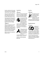
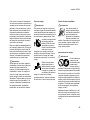
Proper Clothing
!Warning!
To reduce the risk of injury, the operator
should wear proper protective apparel."
The deflector provided with your
brushcutter may not protect the operator
from all foreign objects (gravel, glass,
wire, etc.) thrown by the rotating cutting
attachment. Thrown objects may also
ricochet and strike the operator.
FS 55
English / USA
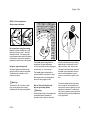
!Warning!
To reduce the risk of injury
to your eyes never
operate a brushcutter
unless wearing goggles or
properly fitted safety
glasses with adequate top
and side protection complying with ANSI
Z 87.1 (or your applicable national
standard). To reduce the risk of injury to
your face STIHL recommends that you
also wear a face shield or face screen
over your goggles or safety glasses.
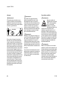
!Warning!
Brushcutter noise may
damage your hearing.
Wear sound barriers (ear
plugs or ear mufflers) to
protect your hearing.
Continual and regular
users should have their hearing checked
regularly.
Protect your hands with
gloves when handling the
brushcutter and the
cutting tool. Heavy-duty,
nonslip gloves improve
your grip and protect your
hands.
FS 55
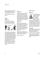
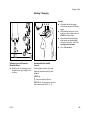
Clothing must be sturdy
and snug-fitting, but allow
complete freedom of
movement. Avoid loosefitting jackets, scarfs,
neckties, jewelry, flared or
cuffed pants, unconfined longhair or
anything that could become caught on
branches, brush or moving parts of the
unit. Wear long pants made of heavy
material to protect your legs. Do not
wear shorts, pants, sandals or go bare
foot. Secure hair so it is above shoulder
level.
Good footing is most
important in brushcutter
work. Wear sturdy boots
with nonslip soles. Steeltoed safety boots are
recommended.
THE BRUSHCUTTER
For illustrations and definitions of the
brushcutter parts see the chapter on
"Parts and Controls".
!Warning!
Never modify a brushcutter in any way.
Only attachments supplied by STIHL or
expressly approved by STIHL for use
with the specific STIHL brushcutter
models are authorized. Although certain
unauthorized attachments are useable
for the STIHL brushcutter, their use may,
in fact, be extremely dangerous.
Wear an approved safety
hard hat to reduce the risk
of injury to your head
when there is a danger of
head injuries.
5
English / USA
THE USE OF THE
BRUSHCUTTER
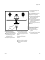
Fueling
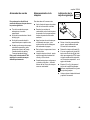
A
Your STIHL brushcutter uses an oilgasoline mixture for fuel (see the chapter on "Fuel" of your owner's manual).
Transporting the brushcutter
Adjust carrying harness and hand grip to
suit your size before starting work. The
machine should be properly balanced as
specified in your owner's manual for
proper control and less fatigue in
operation.
Always check your brushcutter for
proper condition and operation before
starting, particularly the throttle trigger,
throttle trigger interlock (if applicable),
stopswitch, cutting tool, deflector and
harness.
6
B
000BA007 KN
Preparation for the use of the
brushcutter
000BA006 KN
!Warning!
Always turn off the engine and make
sure the cutting attachment has stopped before putting a brushcutter down.
When transporting your brushcutter in a
vehicle, properly secure it to prevent
turnover, fuel spillage and damage to the
brushcutter. Keep metal cutting tools
covered with the transport guard
(optional accessory).
!Warning!
Gasoline is an extremely
flammable fuel. If spilled
and ignited by a spark or
other ignition source, it
can cause fire and serious
burn injury or property
damage. Use extreme caution when
handling gasoline or fuel mix.
Do not smoke or bring any fire or flame
near the fuel or brushcutter.
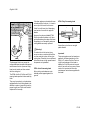
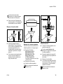
Fueling Instructions
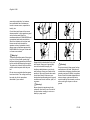
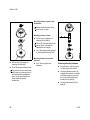
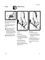
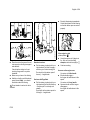
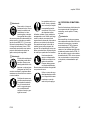
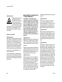
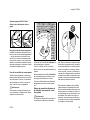
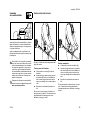
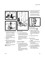
Arrows on the deflector (A) and stop (B)
show the correct direction of rotation of
the cutting tool.
The throttle trigger must move freely and
always spring back to the idle position.
The cutting tool must be properly
tightened and in safe operating
condition. Inspect for loose parts (nuts,
screws, etc.) and for cracked, bent,
warped or damaged blades.
!Warning!
Fuel your brushcutter in well-ventilated
areas, outdoors. Always shut off the
engine and allow it to cool before
refueling. Gasoline vapor pressure may
build up inside the fuel tank depending
on the fuel used, the weather conditions
and the tank venting system.
FS 55
English / USA
In order to reduce the risk of burns and
other personal injury from escaping gas
vapor and fumes, remove the fuel filler
cap on your brushcutter carefully so as
to allow any pressure build-up in the
tank to release slowly. Never remove
fuel filler cap while engine is running.
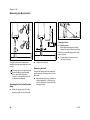
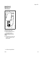
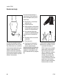
Cap with Grip
Screw Cap
!Warning!
!Warning!
In order to reduce the risk of fuel spillage
and fire from an improperly tightened
fuel cap, correctly position and tighten
the fuel cap in the fuel tank opening.
Select bare ground for fueling and move
at least 10 feet (3 m) from the fueling
spot before starting the engine. Wipe off
any spilled fuel before starting your
brushcutter and check for leakage.
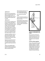
To do this with this STIHL
cap, raise the grip on the
top of the cap until it is
upright at a 90° angle.
Insert the cap in the fuel
tank opening with the
triangular marks on the grip of the cap
and on the fuel tank opening lining up.
Using the grip, turn the cap firmly
clockwise as far as it will go (approx. a
quarter turn).
Unit vibrations can cause
an improperly tightened
fuel filler cap to loosen or
come off and spill
quantities of fuel. In order
to reduce the risk of fuel
spillage and fire, tighten the fuel filler cap
by hand with as much force as possible.
!Warning!
Check for fuel leakage while refueling
and during operation. If fuel or oil
leakage is found, do not start or run the
engine until leak is fixed and spilled fuel
has been wiped away. Take care not to
get fuel on your clothing. If this happens,
change your clothing immediately.
Different models may be equipped with
different fuel caps.
FS 55
Fold the grip flush with the
top of the cap. If the grip
does not lie completely
flush with the cap and the
detent on the grip does
not fit in the
corresponding recess in the filler neck,
the cap is not properly seated and
tightened and you must repeat the
above steps.
Operating instructions
! Warning!
Improper use of
any brushcutter
can cause serious
or fatal personal
injury. To reduce
the risk of personal injury to the operator
from blade contact and thrown objects,
make sure your unit is equipped with the
proper deflector, handle and harness for
the type of cutting attachment being
used (see chart in chapter on "Approved
Combinations of Cutting Tool, Deflector,
Handle and Harness").
7
English / USA
Keep the deflector (and the skirt where
appropriate) adjusted properly at all
times (see chapter on mounting the
various cutting tools of your owner's
manual).
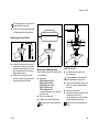
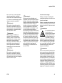
Starting
!Warning!
Your brushcutter is a one-person
machine. Once started, it may fling
foreign objects for a great distance.
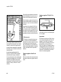
15m (50ft)
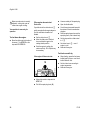
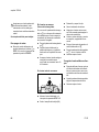
To reduce the risk of eye and other injury
insure that bystanders are at least 50
feet (15 m) away. Bystanders should be
encouraged to wear eye protection. Stop
the engine and cutting tool immediately
if you are approached. Start and operate
your brushcutter without assistance. For
specific starting instructions, see the
appropriate section of your manual.
Place the brushcutter on firm ground or
other solid surface in an open area.
Maintain a good balance and secure
footing.
8
!Warning!
To reduce the risk of injury from loss of
control, be absolutely sure that the
cutting tool is clear of you and all other
obstructions and objects, including the
ground, because when the engine starts
at starting-throttle, engine speed will be
fast enough for the clutch to engage and
turn the cutting tool.
!Warning!
When you pull the starter grip, don't
wrap the starter rope around your hand.
Do not allow the grip to snap back, but
guide the starter rope to rewind it
properly. Failure to follow this procedure
may result in injury to hand or fingers
and may damage the starter
mechanism.
With the engine running but at idle,
attach the brushcutter to the spring hook
of your harness (see appropriate
chapter of this manual).
Catalytic converter
!Warning!
Some STIHL brushcutter
models are equipped with
a catalytic converter,
which is designed to
reduce the exhaust
emissions of the engine
by a chemical process in the muffler.
Due to this process, the muffler does not
cool down as rapidly as conventional
mufflers when the engine returns to idle
or is shut off. To reduce the risk of fire
and burn injuries, the following specific
safety precautions must be observed.
!Warning!
Since a muffler with a catalytic converter
cools down less rapidly than conventional mufflers, always set your
brushcutter down in the upright position
and never locate it where the muffler is
near dry brush, grass, wood chips or
other combustible materials while it is
still hot.
FS 55
English / USA
Let the engine cool down sitting on
concrete, metal, bare ground or solid
wood (e.g. the trunk of a felled tree)
away from any combustible substances.
!Warning!
To reduce the risk of fire or burn injury,
let the unit cool down before refueling
your brushcutter after use.
!Warning!
Never disassemble or modify your
muffler. The muffler could be damaged
and cause an increase in heat radiation
or sparks, thereby increasing the risk
of fire or burn injury. You may also
permanently damage the engine. Have
your muffler serviced and repaired by
your STIHL Servicing Dealer only.
!Warning!
To reduce the risk of fire or burn injury,
keep the area around the muffler clean.
Remove all debris such as pine needles,
branches or leaves.
FS 55
!Warning!
An improperly mounted or damaged
cylinder housing or a damaged/
deformed muffler shell may interfere
with the cooling effect of the catalytic
converter. To reduce the risk of fire or
burn injury, do not continue work with a
damaged or improperly mounted
cylinder housing or a damaged/
deformed muffler shell. Your catalytic
converter is furnished with screens
designed to reduce the risk of fire from
the emission of hot particles. Due to the
heat from the catalytic reaction, these
screens will normally stay clean and
need no service or maintenance. If you
experience loss of performance and you
suspect a clogged screen, have your
muffler maintained by a STIHL Servicing
Dealer.
Working Conditions
Operate and start your brushcutter only
outdoors in a ventilated area.
Operate the brushcutter under good
visibility and daylight conditions only.
Work carefully.
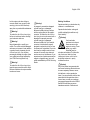
!Warning!
Your brushcutter
produces toxic exhaust
fumes as soon as the
engine is running. These
gases (e.g. carbon
monoxide) may be
colorless and odorless. To reduce the
risk of serious or fatal injury from
inhaling toxic fumes, never run the
brushcutter indoors or in poorly
ventilated locations.
!Warning!
Use of this product can generate dust
and fumes containing chemicals known
to cause respiratory disease, cancer,
birth defects, or other reproductive
harm. If you are unfamiliar with the risks
associated with the particular dust or
fume at issue, consult your employer,
governmental agencies such as OSHA
and NIOSH and other sources on
hazardous materials. California and
9
English / USA
002BA024 LÄ
!Warning!
The muffler and other parts of the engine
(e.g. fins of the cylinder, spark plug)
become hot during operation and remain
hot for a while after stopping the engine.
To reduce risk of burns do not touch the
muffler and other parts while they are
hot.
Do not cut any material other than grass,
brush and wood. The cutting tools may
be used only for the operations
described in your manual.
002BA080 KN
002BA055 KN
Control dust and fumes at the source
where possible. In this regard use good
work practices and follow the
recommendations of OSHA/NIOSH and
occupational and trade associations.
When the inhalation of toxic dust and
fumes cannot be eliminated, the
operator and any bystanders should
always wear a respirator approved by
NIOSH/MSHA for the type of dust and /
or fumes encountered.
002BA054 KN
some other authorities, for instance,
have published lists of substances
known to cause cancer, reproductive
toxicity, etc.
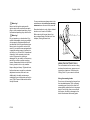
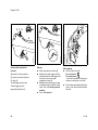
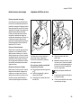
Always hold the brushcutter firmly with
both hands. Wrap your fingers tightly
around the handles, keeping the
handles cradled between your thumb
and forefinger. Keep your hands in this
position to have your brushcutter under
control at all times. Make sure your
brushcutter handles and grip are in good
condition and free of moisture, pitch, oil
or grease.
!Warning!
!Warning!
Do not overreach. Keep proper footing
and balance at all times. Special care
must be taken in slippery conditions (wet
ground, snow) and in difficult, overgrown
terrain. Watch for hidden obstacles such
as tree stumps, roots and ditches to
avoid stumbling. Be extremely cautious
when working on slopes or uneven
ground.
Never attempt to operate any brushcutter with one hand. Loss of control of
the brushcutter resulting in serious or
fatal injury may result.
10
FS 55
English / USA
!Warning!
Before cutting, inspect the
area for stones, glass,
pieces of metal, trash or
other solid objects. The
cutting attachment could
throw objects of this kind.
!Warning!
When using rigid blades, avoid cutting
close to fences, sides of buildings, tree
trunks, stones or other such objects that
could cause the brushcutter to kick out
or could cause damage to the blade.
STIHL recommends use of the nylon line
heads or PolyCut head for such jobs. In
addition, be alert to an increased
possibility of ricochets in such situations.
!Warning!
This brushcutter is normally to be used
at ground level with the cutting attachment parallel to the ground. Use of a
brushcutter above ground level or with
the cutting attachment perpendicular to
the ground may increase the risk of
injury, since the cutting attachment is
more fully exposed and the brushcutter
may be more difficult to control. Never
use your brushcutter as a hedge
trimmer.
FS 55
Do not operate using the starting throttle
lock as you do not have control of the
engine speed. See section of your
owner's manual on the proper use of the
slide control.
If the cutting tool or deflector becomes
clogged or stuck, always turn off the
engine and make sure the cutting tool
has stopped before cleaning. Grass,
weeds, etc. should be cleaned off the
cutting tool at regular intervals.
!Warning!
During cutting, check the tightness and
the condition of the cutting tool at regular
intervals. If the behavior of the tool
changes, stop the engine immediately,
and check the nut securing the tool for
tightness and the cutting tool for cracks
and damage. Replace cracked, bent,
warped, damaged or dull cutting tools
immediately. Such tools may shatter at
high speed and cause serious or fatal
injury.
!Warning!
A loose blade may cause the blade to
vibrate, crack, break or come off the
brushcutter, which may result in serious
or fatal injury. Make sure that the blade
is properly tightened. Use the wrench
supplied or one of sufficient length to
obtain the proper torque. If the blade
loosens after being properly tightened,
stop work immediately. The retaining nut
may be worn or damaged and should be
replaced. Never use unauthorized parts
to secure the blade. If the blade
continues to loosen, see your STIHL
dealer. Never use a brushcutter with a
loose blade.
Do not attach any blade to a unit without
proper installation of all required parts.
Never use unauthorized parts to secure
the blade. Failure to use the proper parts
may cause the blade to fly off and
seriously injure the operator or
bystanders.
11
English / USA
!Warning!
Keep hands and feet
away from cutting tool.
Never touch a rotating
cutting tool with your hand
or any part of your body. It
continues to rotate for a
short period after the throttle trigger is
released (flywheel effect).
Important adjustments
MAINTENANCE, REPAIR AND
STORING
Maintenance, replacement, or repair
of the emission control devices and
systems may be performed by any
nonroad engine repair establishment
or individual. However if you claim
warranty coverage for a component
which has not been serviced or
maintained properly or if
nonapproved replacement parts were
used, STIHL may deny warranty.
!Warning!
!Warning!
To reduce the risk of personal injury from
loss of control or contact with the
running cutting tool, do not use a cutting
tool with incorrect idle adjustment. At
correct idle speed, the cutting tool
should not move. For directions on how
to adjust idle speed, see the appropriate
section of your owner's manual.
Use only identical STIHL replacement
parts for maintenance and repair. Use of
non-STIHL parts may cause serious or
fatal injury.
If you cannot set the correct idle speed,
have your STIHL dealer check your
brushcutter and make proper
adjustments and repairs.
Follow the maintenance and repair
instructions in the appropriate section of
your owner's manual. Please refer to the
maintenance chart on the last pages of
this manual.
!Warning!
Always stop the engine and make sure
that the cutting tool is stopped before
doing any maintenance or repair work or
cleaning the brushcutter. Do not attempt
any maintenance or repair work not
described in your owner's manual. Have
such work performed at your STIHL
service shop only.
!Warning!
To reduce the risk of injury from contact
with a rotating head always stop engine
and allow the mowing head to
completely stop before you adjust the
nylon line.
!Warning!
Never repair damaged cutting attachments by welding, straightening or
modifying the shape. This may cause
parts of the cutting tool to come off and
result in serious or fatal injuries.
!Warning!
To reduce the risk of fire and burn
injuries, check fuel filler cap for leaks at
regular intervals. Use the specified
spark plug and make sure it and the
ignition lead are always clean and in
good condition. Always press spark plug
boot snugly onto spark plug boot of the
proper size. (Note: If boot has
detachable SAE adapter nut, it must be
attached.) A loose connection between
spark plug boot and ignition wire
connector in the boot may create arcing
that could ignite combustible fumes and
cause a fire.
Wear gloves when handling or doing
maintenance on blade.
12
FS 55
English / USA
Never test the ignition system with
ignition wire boot removed from spark
plug or with unseated spark plug, since
uncontained sparking may cause a fire.
!Warning!
Do not operate your brushcutter if the
muffler is damaged, missing or modified.
An improperly maintained muffler will
increase the risk of fire and hearing loss.
Never touch a hot muffler or burn will
result. If your muffler was equipped with
a spark-arresting screen to reduce the
risk of fire (e.g. in the USA, Canada and
Australia), never operate your brushcutter if the screen is missing or
damaged. Do not modify or remove any
part of the muffler or spark arresting
screen. Remember that the risk of forest
fires is greater in hot or dry weather.
Keep cutting tool sharp. Tighten all nuts,
bolts and screws, except the carburetor
adjustment screws, after each use.
Additionally, the daily maintenance
schedule for your brushcutter set forth in
your STIHL Owner's Manual should be
strictly followed.
FS 55
For any maintenance please refer to the
maintenance chart and to the warranty
statement near the end of this manual.
Store brushcutter in a dry, high or locked
location out of reach of children.
Before storing for longer than a few
days, always empty the fuel tank. See
chapter „Storing the machine“.
002BA018 LÄ
!Warning!
USING THE CUTTING TOOLS
For an illustration of the various cutting
tools and instructions on proper mounting see the chapter on "Mounting the
Cutting Tools" in your owner's manual.
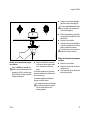
Using the mowing heads
Do not use with mowing line larger than
the intended diameter. With a properly
mounted guard, the built-in cutter will
automatically adjust the line to its proper
length. Overly long lines can overload
the engine, resulting in damage to the
clutch mechanism and nearby parts.
13
English / USA
If the lawn edges are planted with trees
or bordered by a fence etc., it is best to
use a nylon line head. It achieves a
"softer" cut with less risk of damaging
tree bark etc. than with the polymer
blades.
STIHL PolyCut mowing head
000BA015 KN
!Warning!
The damaged clutch may cause the
cutting attachment to rotate at idle speed
and increase the risk of personal injury
from loss of control and from contact
with the cutting tool.
The STIHL AutoCut, PolyCut and FixCut
mowing heads produce a clean and tidy
finish.
To reduce the risk of serious injury,
never use wire or metal-reinforced line
or other material in place of the nylon
cutting lines. Pieces of wire could break
off and be thrown at high speed toward
the operator or bystanders.
STIHL AutoCut mowing head
Nylon cutting cord advances automatically when tapped against the
ground.
002BA049 KN
However, the polymer bladed STIHL
PolyCut produces a better cut if there
are no plants along the edge of the lawn.
Sharpening is not necessary and worn
cutting blades are easily replaced.
Uses either nylon lines or nonrigid
plastic blades
Important!
Three rectangular wear limit marks are
applied to the base (periphery) of the
PolyCut. To reduce the risk of serious
injury from breakage of the head or
blades, the PolyCut must not be used
when it has worn as far as one of these
marks. It is important to follow the
maintenance instructions supplied with
the head!
They may be used only on brushcutters
equipped with a line-limiting blade in the
deflector in order to keep the line at the
proper length (see "Parts and Controls"
chapter of this manual).
14
FS 55
English / USA
STIHL FixCut mowing head
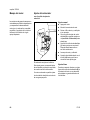
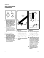
Using the grass-cutting blade
All kinds of grass and weeds can be
easily cut with the grass-cutting blade.
The brushcutter is swept in an arc
similiar to a scythe.
000BA020 KN
Do not continue using the mowing
head if the raised moldings (1) on the
base are missing or worn – see right
illustration above. The mowing head
may otherwise shatter and flying objects
could result in injury to the operator or
bystanders. Install a new mowing head.
The 4-tooth grass cutting blade is
intended to cut grass and weeds.
It has 4 cutting knives with cutting edges
on both sides, i.e. front and rear.
The 8-tooth grass cutting blade is
recommended for cutting fern or reed.
Both blades have to be resharpened
when all cutting edges are dull.
!Warning!
To reduce the risk of serious or fatal
injury never attempt to cut woody
materials with the grass-cutting blade.
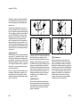
Risk of "kickout" (blade thrust)
with all rigid cutting blades
!Warning!
Kickout (blade thrust) is the sudden and
uncontrolled motion towards the
operator's right or rear that can occur
FS 55
000BA012 KN
Observe wear indicators.
when the shaded area of the rotating
blade comes in contact with a solid
object like a tree, rock, bush or wall.
The rapid counterclockwise rotation of
the blade may be stopped or slowed,
and the cutting attachment may be
thrown in an area to the right or to the
rear.
This kickout (blade thrust) may cause
loss of control of the brushcutter and
may result in serious or fatal injury to the
operator or bystanders. To reduce the
risk of injury, extreme caution should be
used when cutting with the shaded area
of any rigid blade.
15
English / USA
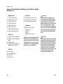
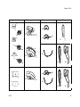
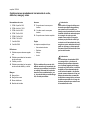
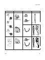
Approved Combinations of Mowing Tool, Deflector, Handle
and Harness
Mowing tools
Harnesses
1 STIHL SuperCut 20-2
17 Shoulder strap may be used
2 STIHL AutoCut C 25-2
18 Shoulder strap must be used
3 STIHL AutoCut 25-2
19 Full harnesss may be used
4 STIHL TrimCut 30-2
5 STIHL PolyCut 20-3
6 STIHL FixCut 25-3
7 Grass cutting blade 230-4
8 Grass cutting blade 230-8
Deflectors
9 Deflector for mowing heads
10 Deflector for all mowing tools
with
11 Skirt and blade
12 Deflector for all mowing tools
without skirt and blade
Handles
13 Loop handle
Equipment
The complete unit includes:
-
Mowing tool
Deflector
Handle
Harness (bike unit only)
Select the correct combination from
the table according to the mowing
tool you intend to use. Read the table
horizontally from left to right. Other
combinations, e.g. reading the table
diagonally, are not permitted.
Warning!
To reduce the risk of injury from
thrown objects and blade contact,
never operate your unit without the
proper deflector for the mowing
attachment being used. To reduce the
risk of injury from loss of control
and / or contact with the mowing tool,
make sure your unit is equipped with
a proper handle and harness for the
type of mowing attachment beeing
used.
Warning!
Stihl brushcutters with a loop handle
without barrier bar may be used only
with the above mentioned mowing
head with nylon line or plastic blades.
Other plastic or metal mowing tool
may only be used on brushcutters
with a bike-handle or loop-handle
with barrier bar in order to reduce the
risk of personal injury through
contact with the mowing tool.
14 Loop handle with
15 Barrier bar
16 Bike handle
16
FS 55
FS 55
12
8
6
7
14
16
15
18
19
18
19
002BA127 KN
16
002BA125 KN
17
002BA127 KN
14
002BA005 K
Handles
002BA005 K
3
002BA002 K
13
002BA003 K
2
002BA001 K
681FK023
Deflectors
002BA003 K
10
681BA002 KN
681FK037 KN
9
681FK021
681FK111 KN
681FK011
681FK003
Mowing tools
002BA001 K
681FK014
681FK006
English / USA
Harnesses/Straps
1
15
4
11
5
17
English / USA
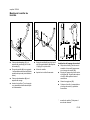
Mounting the Bike Handle
5
11
A
4
7
4
10
9
3
4
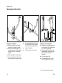
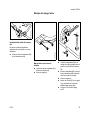
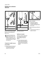
Fitting the handlebar
:
Place the clamp (1) and handle
support (2) on the drive tube (3).
:
Position the handlebar (4) in the
handle support – the rubber grip (5)
must be on the left (viewed from
engine).
:
Place clamp (6) on handle support.
:
Insert screws (7) in the holes and
screw down as far as stop in clamp.
233BA018 KN
3
233BA025 KN
2
1
12
8
:
Secure handlebar (4) on the drive
tube (3) at distance (A) of approx.
15 cm (6 in) from the powerhead.
:
Align the handlebar.
:
Tighten down the screws firmly.
12
233BA038 KN
6
Fitting the control handle
:
Release the screw (8) and remove it
with the washer. The nut (9) remains
in the control handle (10).
:
Push the control handle onto the
handlebar (4) – the throttle trigger
(11) must point towards the
gearhead.
:
Line up the holes (12).
:
Fit screw and washer in control
handle and tighten down firmly.
* see “Guide to Using this Manual”
18
FS 55
English / USA
Mounting the Loop Handle
14
233BA027 KN
13
2
4
14
2
3
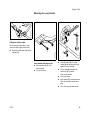
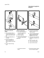
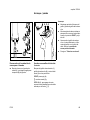
Fitting the throttle cable
Do not kink the throttle cable - make
sure the throttle trigger moves freely.
Push the throttle cable (13) into the
retainer (14).
5
1
6
002BA098 KN
:
1
Loop handle with barrier bar
:
Insert square nuts (1) in the
barrier bar (2).
:
Line up the holes.
002BA099 KN
13
7
:
Place the clamp (3) in the loop
handle (4) and position them both
against the drive tube (5).
:
Fit the clamp (6) and place the
barrier bar (2) in position.
Note correct position.
FS 55
:
Line up the holes.
:
Insert screws (7) in holes and screw
them into the barrier bar as far as
stop.
:
Go to “Securing the loop handle”.
19
English / USA
Fitting the Carrying Eye
8
7
8
7
1
4
A
9
4
10
3
1
1
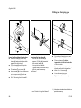
Loop handle without barrier bar
Securing the loop handle
:
Place the clamp (3) in the loop
handle (4) and position them both
against the drive tube (5).
:
Secure the loop handle (4)
approx. 8”/20cm (A) forward of
the control handle (9).
:
Fit the clamp (6) and line up the
holes.
:
Line up the loop handle.
:
Tighten down the screws firmly –
lock the nuts if necessary.
:
Fit washers (7) on screws (8).
:
Insert screws (8) in holes and screw
on the square nuts (1) as far as
stop.
:
10= Sleeve*
:
For position of carrying eye1) see
"Parts and Controls"
:
Place the clamp (1) with the
tapped hole on the left-hand side
of the drive tube.
:
Squeeze the two ends of the clamp
together and hold in that position.
:
Insert M 6 x 14 screw (2).
:
Line up the carrying eye.
:
Tighten down the screw firmly.
Go to “Securing the loop handle”.
*
20
2
002BA142 KN
1
002BA147 KN
6
002BA136 KN
5
see “Guide to Using this Manual”
1) Included as standard or available as
special accessory
FS 55
English / USA
Mounting the Deflector
Mounting the Cutting Tools
1
002BA104 KN
4
4
3
1
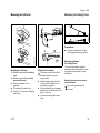
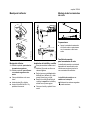
Preparations
2
:
Mounting the deflector
002BA103 KN
3
002BA102 KN
5
Fitting skirt and blade
1 = Deflector approved for all cutting
tools
2 = Deflector approved for use with
mowing heads only
:
Place the deflector on the
gearhead.
:
Fit the plate (3) and line it up.
:
Insert M 5 x 18 screws and tighten
down firmly.
FS 55
These parts must be fitted to the
deflector (1) when you use a
mowing head:
:
Slide the lower guide slot of the
skirt (4) onto the deflector (1) – it
must snap into position.
:
Push the blade (5) into the upper
guide slot on the skirt and line it up
with the first hole.
:
Fit the screw and tighten it down
firmly.
Lay your brushcutter on its back
with the gearhead facing upward.
Mounting Hardware
for Cutting Tools
The mounting hardware supplied
depends on the cutting tool that comes
as original equipment with the new
brushcutter.
Mounting hardware is not packed
with the machine
Only mowing heads may be
mounted.
21
English / USA
Mounting hardware is packed with
the machine
3
Mowing heads and metal cutting
tools may be mounted.
4
Mounting hardware is loose
:
5
The nut (3), rider plate (4) and thrust
washer (5) are in the parts kit
supplied with the machine.
1
002BA164 KN
:
2
:
Pull the hose (1) (protector for
shipping) off the shaft (2).
:
Go to "Mounting the Mowing Head".
If you want to mount a metal cutting
tool in place of a mowing head, you
will need the following additional
parts: Nut (3), rider plate (4) and
thrust washer (5) (special
accessories).
22
Pull the hose (1) (protector for
shipping) off the shaft (2).
Go to "Mounting the Mowing Head"
or "Mounting Metal Cutting Tools".
Mounting hardware is secured to
gearhead
:
Go to "Removing Mounting
Hardware"
Removing Mounting Hardware
:
Block the shaft – see next section
on "Blocking the Output Shaft".
:
Use the combination wrench (6)
(supplied with machine or available
as special accessory) to unscrew
the nut (3) clockwise (left-hand
thread) from the shaft (2).
:
Pull the thrust washer (5) off the
shaft (2).
FS 55
English / USA
The rider plate (4) is in the parts kit
supplied with the machine.
:
Go to "Mounting the Mowing Head"
or "Mounting Metal Cutting Tools".
Blocking the Output Shaft
2
7
:
:
7
002BA081 KN
8
002BA166 KN
1
Insert the stop pin or screwdriver (7)
(supplied with machine or available
as special accessories) in the hole
(8) in the gearhead as far as stop –
apply slight pressure.
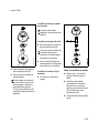
Mounting the Mowing Head
STIHL FixCut 25-2
:
Rotate nut or cutting tool on the
shaft (2) until the stop pin slips into
position and blocks the shaft.
Keep instruction sheet for mowing head
in a safe place.
:
FS 55
Screw the
STIHL SuperCut 20-2,
STIHL AutoCut 25-2,
STIHL AutoCut C 25-2,
STIHL TrimCut 30-2,
STIHL PolyCut 20-3
counterclockwise onto the shaft (1)
as far as stop.
Place the mowing head on the
thrust plate (2).
Collar (arrows) must locate in the
mowing head’s mounting hole
:
Push the thrust washer (3) over the
shaft (1) so that it locates against
the base.
:
:
:
Block the output shaft.
:
Tighten down the mowing head.
Block the output shaft.
Screw the mounting nut (4) with the
combination wrench (5)
counterclockwise on to the output
shaft and tighten down firmly.
Remove the tool used to block the
shaft.
Remove the tool used to block the
shaft.
23
English / USA
Removing the Mowing Head
STIHL AutoCut
:
:
Block the output shaft.
STIHL SuperCut 20-2,
STIHL AutoCut 25-2,
STIHL AutoCut C 25-2,
STIHL TrimCut 30-2,
STIHL PolyCut 20-3
:
Unscrew the mowing head
clockwise.
STIHL FixCut 25-2
:
Use the combination wrench to
unscrew the mounting nut clockwise
from the output shaft
If the mounting nut is too loose, fit a
new one
Adjusting Nylon Line
STIHL SuperCut
Fresh line is advanced automatically if
remaining line is still min. 2 1/2" (6 cm)
long. The blade on the deflector trims
overlong line to the correct length.
24
Hold the rotating mowing head
above the ground – tap it on the
ground once – about 1 1/4" (3 cm)
fresh line is advanced.
The blade on the deflector trims
overlong line to the correct length –
avoid tapping head more than once at a
time.
Line feed operates only if both lines
still have a minimum length of 1"
(2.5 cm).
All other mowing heads
Refer to the instructions supplied with
the mowing head.
To reduce the risk of injury, always
shut off the engine before adjusting
the nylon line by hand.
Replacing Nylon Line or Cutting
Blades
Refer to the instructions supplied with
the mowing head.
FS 55
English / USA
:
Collar (see arrow) must locate in
cutting tool’s mounting hole.
8
1
6
2
5
3
:
Slip thrust washer (5) and rider plate
(6) over the output shaft (7).
:
Block the output shaft.
:
Screw the mounting nut (8) onto the
output shaft counterclockwise and
tighten down firmly.
If the mounting nut is too loose, fit a
new one.
7
002BA120 KN
4
Mounting metal cutting tools
Remove the skirt and blade from
the deflector before mounting Grass
cutting blade 230-4 (1) or Grass
cutting blade 230-8 (2).
See chapter “Mounting the Deflector”
:
Place the cutting tool (3) on the
thrust plate (4).
Lay your brushcutter on its back
with the gearhead facing upward.
Cutting edges of (1) may point in either
direction.
Removing metal cutting tool
:
Block the output shaft.
:
Unscrew the mounting nut
clockwise.
:
Take the parts off the shaft - do not
remove the thrust plate (4).
Cutting edges of (2) must point
clockwise.
Direction of rotation is marked by
arrow on inside of mowing head
deflector.
FS 55
25
English / USA
Fuel
This engine is certified to operate on
unleaded gasoline and the STIHL twostroke engine oil at a mix ratio of 50:1.
Your engine requires a mixture of highquality gasoline and quality two-stroke
air cooled engine oil.
Use mid-grade unleaded gasoline with a
minimum octane rating of 89 (R+M/2). If
the octane rating of the mid-grade
gasoline in your area is lower, use
premium unleaded fuel.
Fuel with a lower octane rating may
increase engine temperatures. This, in
turn, increases the risk of piston seizure
and damage to the engine.
The chemical composition of the fuel is
also important. Some fuel additives not
only detrimentally affect elastomers
(carburetor diaphragms, oil seals, fuel
lines, etc.), but magnesium castings and
catalytic converters as well. This could
cause running problems or even
damage the engine. For this reason
STIHL recommends that you use only
nationally recognized high-quality
unleaded gasoline!
26
Use only STIHL two-stroke engine oil or
equivalent high-quality two-stroke
engine oils that are designed for use
only in air cooled two-cycle engines.
We recommend STIHL 50:1 two-stroke
engine oil since it is specially formulated
for use in STlHL engines.
Do not use BIA or TCW rated (twostroke water cooled) mix oils or other
mix oils that state they are for use in both
water cooled and air cooled engines
(e.g., outboard motors, snowmobiles,
chainsaws, mopeds, etc.).
Take care when handling gasoline.
Avoid direct contact with the skin and
avoid inhaling fuel vapor. When filling at
the pump, first remove the canister from
your vehicle and place the canister on
the ground before filling. Do not fill fuel
canisters that are sitting in or on a
vehicle.
Fuel mix ages
Only mix sufficient fuel for a few days
work, not to exceed 3 months of storage.
Store in approved fuel-canisters only.
When mixing, pour oil into the canister
first, and then add gasoline. Close the
canister and shake it vigorously by hand
to ensure proper mixing of the oil with
the fuel.
Gasoline
Oil (STIHL 50:1 or
equivalent high-quality oils)
US gal.
1
2 1/2
5
US fl.oz
2.6
6.4
12.8
Dispose of empty mixing-oil canisters
only at authorized disposal locations.
The canister should be kept tightly
closed in order to avoid any moisture
getting into the mixture.
The machine‘s fuel tank and the canister
in which fuel mix is stored should be
cleaned as necessary.
FS 55
English / USA
Fitting the Harness
232BA046 KN
Fueling
Before fueling, clean the filler cap and
the area around it to ensure that no dirt
falls into the tank.
Always thoroughly shake the mixture in
the canister before fueling your
machine.
In order to reduce the risk of burns
or other personal injury from
escaping gas vapor and fumes,
remove the fuel filler cap carefully
so as to allow any pressure build-up
in the tank to release slowly.
After fueling, tighten fuel cap as
securely as possible by hand.
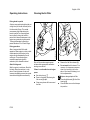
The type and style of harness depend on
the market.
Full harness
:
Put on the full harness (1).
Shoulder strap*
:
Adjust length until the spring hook
(2) is about a hand’s width below
your right hip.
:
Balance the brushcutter.
:
Put on the shoulder strap (1).
:
Adjust length until the spring hook
(2) is about a hand’s width below
your right hip.
:
Balance the brushcutter.
The use of the shoulder strap is
described in chapter “Approved
Combinations of Cutting Tool, Deflector,
Handle and Harness”.
FS 55
The use of the harness is described in
chapter “Approved Combinations of
Cutting Tool, Deflector, Handle and
Harness”.
27
English / USA
A
002BA034 KN
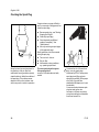
Balancing the Brushcutter
Floating position
A
Mowing tools
Mowing heads and grass cutting
blades should just touch the ground.
When the correct floating position has
been reached:
:
The type and style of harness and
carabiner (spring hook) depend on the
market.
The carrying ring is integrated in the
control handle on loop-handled
units – see "Main Parts and
Controls". Loop-handled units do
not need to be balanced.
Attaching the Unit to the Shoulder
Strap
:
28
:
Tighten down the screw on the
carrying ring firmly.
Loosen the screw (3).
Balancing the Unit
Proceed as follows until the conditions
specified under "Floating position" have
been met:
:
Adjust the carrying ring – tighten the
screw moderately – let the unit go
until it is balanced – then check the
floating position.
Attach the spring hook (1) to the
carrying ring (2) on the drive tube.
FS 55
English / USA
Starting / Stopping
Starting
6 5 4
P
7
3
:
Hold down the throttle trigger
interlock and squeeze the throttle
trigger.
:
While holding both levers in this
position, move the slide control to
START and hold it there.
:
Now release the throttle trigger,
slide control and throttle trigger
interlock in that order. This is the
starting throttle poistion.
:
Go to “All versions”.
STO
1
Detaching the Unit from the
Shoulder Strap
:
Press the bar on the spring hook (1)
and pull the carrying ring (2) out of
the hook.
233BA037 KN
2
Version with bike handle
Controls
Throttle trigger interlock (1), throttle
trigger (2) and slide control (3) with
positions:
START (4),
# - normal run position (5) and
STOP–O (6) - to stop engine, move the
slide control in direction of h (7).
FS 55
29
English / USA
3 1 2
9
4
8
6
233BA043 KN
233BA034 KN
7 6
Version with loop handle
Starting
Controls
:
Move stop switch to position #
Stop switch (1) with positions:
:
Hold down throttle trigger interlock
and squeeze the throttle trigger until
the notch on the tongue (6)
engages the housing.
:
Release the throttle trigger, tongue
and throttle trigger interlock in that
order. This is the starting throttle
position.
:
Go to “All versions”.
# - normal run position (2) and
O - Stop (3)
Throttle trigger interlock (4).
Throttle trigger (5) with
tongue (6) and notch (7).
30
232BA011 KN
5
All versions
:
Set the choke lever (8):
For cold start to g
For warm start to e
– also use this position if the engine
has been running but is still cold.
:
Press fuel pump bulb (9) at least five
times – even when the bulb is filled
with fuel.
FS 55
English / USA
Do not let the starter grip snap back.
Guide it slowly back into the housing
so that the starter rope can rewind
properly.
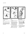
233BA020 KN
:
:
Place the unit on the ground: It must
rest securely on the engine support
and deflector.
Check that the cutting tool is not
touching the ground or any other
obstacles.
:
Make sure you have a firm footing.
:
Hold the unit with your left hand and
press it down firmly - your thumb
should be under the housing.
Do not stand or kneel on the drive
tube!
FS 55
232BA014 KN
233BA014 KN
232TI015 KN
8
If the engine is cold:
(choke position g)
:
Crank the engine until it begins to
fire. After no more than five
attempts, set choke lever (8) to e.
:
Continue cranking.
Standard versions:
:
Pull the starter grip slowly with your
right hand until you feel it engage –
and then give it a brisk strong pull.
Do not pull out the starter rope all
the way – it might break.
As soon as the engine runs:
:
Versions with ErgoStart:
:
Pull the starter grip slowly with your
right hand until you feel the first stop
– and then pull it out slowly and
steadily.
Do not pull out the starter rope to its
full length – it might break.
:
On version with bike handle:
Blip the throttle trigger –
the engine will settle down to idle
speed.
On version with loop handle:
Squeeze throttle until the tongue
disengages –
the engine will settle down to idle
speed.
31
English / USA
Make sure carburetor is correctly
adjusted – cutting tool must not
rotate when engine is idling.
Your machine is now ready for
operation.
If the engine does not start
:
Unscrew and dry off the spark plug.
Choke lever
:
Open the throttle wide.
If you did not set the choke lever to e
quickly enough after the engine began to
fire, the combustion chamber has
flooded.
:
Crank the engine several times with
the starter to clear the combustion
chamber.
:
Refit the spark plug and connect the
spark plug boot - push it down firmly.
:
Set the stop switch or slide control
to I / #
:
Set choke lever to e – even if
engine is cold.
:
Now start the engine.
To shut down the engine:
:
Set the choke lever to e
:
:
Move the slide control, interlock
lever and throttle trigger to the
starting throttle position.
Move the slide control in direction of
the arrow (h) to STOP–O or the
stop switch to STOP / O.
:
Start the engine by pulling the
starter rop firmly. 10 to 20 pulls may
be necessary.
Fuel tank run until dry
If the engine still does not start:
232BA048 KN
10
32
:
Move slide control or stop switch to
STOP / O.
:
Pull off the spark plug boot (10).
:
After refueling, press the fuel pump
bulb at least five times – even when
bulb is filled with fuel.
:
Set the choke lever according to
engine temperature.
:
Now start the engine.
FS 55
English / USA
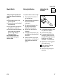
Operating Instructions
Cleaning the Air Filter
During break-in period
A factory new machine should not be run
at high revs (full throttle off load) for the
first three tank fillings. This avoids
unnecessary high loads during the
break-in period. As all moving parts
have to bed in during the break-in
period, the frictional resistances in the
engine are greater during this period.
The engine develops its maximum
power after about 5 to 15 tank fillings.
4
2
During operation
After finishing work
Wait for engine to cool down. Drain the
fuel tank. Store the machine in a dry
place. Check tightness of nuts and
screws (not adjusting screws) at regular
intervals and retighten as necessary.
FS 55
3
1
Dirty air filters reduce engine power
increase fuel consumption and make
starting more difficult.
232BA018 KN
232BA017 KN
After a long period of full-throttle
operation, allow engine to run for a while
at idle speed so that the heat in the
engine can be dissipated by flow of
cooling air. This protects enginemounted components (ignition,
carburetor) from thermal overload.
:
Remove the felt filter element (3).
:
Do not wash the felt element. Fit a
new one. As a temporary measure,
clean it by knocking it out on the
palm of your hand or blowing it out
with compressed air.
If there is a noticeable loss of engine
power
:
Set choke lever to g
:
Press in the tab (1) and swing the
filter cover (2) open.
:
:
Clean away loose dirt from around
the filter.
Place the felt element (3) in the filter
housing (4).
:
Close the filter cover so that it snaps
into position.
Replace damaged parts of filter.
33
English / USA
Motor Management
Exhaust emissions are controlled by the
design of the fundamental engine
parameters and components (e.g.
carburation, ignition, timing and valve or
port timing) without the addition of any
major hardware.
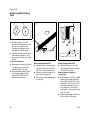
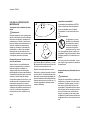
Adjusting the Carburetor
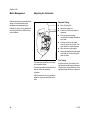
Standard Setting
H
3 /4
L
1
233BA028 KN
LA
:
Shut off the engine.
:
Mount the cutting tool.
:
Check the air filter and replace if
necessary.
:
Turn high speed screw (H)
counterclockwise (max. 3/4 turn) as
far as stop.
:
Carefully screw the low speed
screw (L) down onto its seat. Then
open it one turn counterclockwise
:
Start and warm up the engine.
:
Adjust idle speed with the idle speed
screw (LA) so that the cutting tool
does not rotate.
Fine Tuning
The carburetor comes from the factory
with a standard setting.
This setting provides an optimum fuel-air
mixture under most operating
conditions.
A slight correction of the setting of the
high speed screw (H) may be necessary
if engine power is not satisfactory when
operating at high altitude or at sea level.
With this carburetor it is only possible to
adjust the engine idle speed within fine
limits.
34
FS 55
English / USA
Rule of thumb
Rotate the high speed screw (H) about
/4 turn for every 1000 meter (3300 ft)
change in altitude.
At high altitudes
:
1
Conditions for adjustment
Carry out adjustment with nylon line
cutting head, making sure the
cutting lines are at full length (as far
as limiter blade on deflector).
Carry out standard setting without
altering position of the high speed
screw (H).
:
Warm up engine for about
5 minutes if a metal cutting tool is
fitted or about 3 minutes if a nylon
line cutting head is fitted.
:
Open the throttle wide.
:
At sea level
:
Use standard setting for metal
cutting tools.
:
Turn the high speed screw (H)
clockwise (leaner) no further than
stop until there is no noticeable
increase in engine speed.
Cutting tool rotates when engine is
idling
Turn the high speed screw (H)
counterclockwise (richer) no further
than stop until there is no noticeable
increase in engine speed.
It is possible that maximum engine
speed will already be reached with
the standard setting in each case.
Erratic idling behavior, engine stops
even though setting of LA screw is
correct, poor acceleration
:
Adjusting Idle Speed
It is usually necessary to change the
setting of the idle speed screw (LA)
after every correction to the low speed
screw (L).
:
Warm up engine.
Turn idle speed screw (LA) slowly
counterclockwise until cutting tool
stops rotating and then turn the
screw about another 1/2 to 1 turn in
the same direction.
Idle setting too lean:
Turn low speed screw (L)
counterclockwise (about 1/4 turn)
until the engine runs and
accelerates smoothly.
Erratic idling behavior
:
Idle setting too rich:
Turn low speed screw (L) clockwise
(about 1/4 turn) until the engine runs
and accelerates smoothly.
Engine stops while idling
:
FS 55
Turn idle speed screw (LA) slowly
clockwise until the engine runs
smoothly – cutting tool must not
rotate.
35
English / USA
Checking the Spark Plug
If engine is down on power, difficult to
start or runs poorly at idling speed, first
check the spark plug.
Remove spark plug – see "Starting /
Stopping the Engine".
:
Clean dirty spark plug.
:
Check electrode gap (A) and
readjust if necessary – see
"Specifications".
:
Use only resistor type spark plugs
of the approved range.
000BA002 KN
Rectify problems which have caused
fouling of spark plug:
Wrong fuel mix (too much engine oil in
the gasoline), a dirty air filter and
unfavorable running conditions (mostly
at part throttle etc.) affect the condition of
the spark plug. These factors cause
deposits to form on the insulator nose
which may result in trouble in operation.
36
:
Too much oil in fuel mix.
:
Dirty air filter.
:
Unfavorable running conditions,
e.g. operating at part load.
Fit a new spark plug after approx.
100 operating hours
or earlier if the electrodes are badly
eroded.
1
000BA036 TR
:
To reduce the risk of fire and burn
injury, use only spark plugs
authorized by STIHL. Always press
spark plug boot (2) snugly onto
spark plug terminal (1) of the proper
size. (Note: If terminal has
detachable SAE adapter nut, it must
be attached.)
A loose connection between spark
plug boot and ignition wire
connector in the boot may create
arcing that could ignite combustible
fumes and cause a fire.
FS 55
English / USA
Storing the Machine
To help prolong the wear life of the
starter rope, observe the following
points:
For periods of about 3 months or longer
:
Drain and clean the fuel tank in a
well ventilated area.
:
Pull the starter rope only in the
direction specified.
:
:
Do not pull the rope over the edge of
the guide bushing.
Dispose fuel properly in accordance
with local environmental
requirements.
:
Do not pull out the rope more than
specified since it might break.
:
Do not let the starter grip snap back,
guide it slowly into the housing.
See also chapter “Starting /
Stopping the Engine”!
Have a damaged starter rope
replaced in good time by your
servicing dealer.
Lubricating the
Gearbox
1
2
233BA010 KN
Rewind Starter
:
Run engine until carburetor is dry –
this helps prevent carburetor
diaphragms sticking together.
:
Remove, clean and inspect the
cutting tool.
:
Check grease level regularly - about
every 25 hours of operation.
:
Thoroughly clean the machine – pay
special attention to the cylinder fins
and air filter.
:
Unscrew the filler plug (1).
:
If no grease can be seen on the
inside of the filler plug, screw the
tube (2) of STIHL gear lubricant for
brushcutters - see “Special
Accessories” - into the filler hole.
:
Squeeze up to 1/5 oz (5 g) grease
into the gear housing.
:
Store the machine in a dry, high or
locked location – out of the reach of
children and other unauthorized
persons.
Do not completely fill the gear
housing with grease.
:
FS 55
Refit the filler plug and tighten it
down firmly.
37
English / USA
Sharpening Metal Cutting
Tools
1
1
:
R2
Resharpen the cutters (1) uniformly
- do not alter the contour or the
parent blade (2) in any way.
:
After resharpening about 5 times,
have blade checked on STIHL
balancer 5910 850 2600 and
rebalanced as necessary.
R1
A
3
Resharpen frequently, take away as
little material as possible - two or
three strokes of the file are usually
enough.
:
3
B
Use flat file 0814 212 3310 to
sharpen dull cutting blades. In case
of more serious wear or nicks:
Resharpen with grinder or have
work done by a STIHL dealer.
To avoid out-of-balance:
38
D
3
B
3
C
002BA044 KN
:
2
002BA043 KN
2
002BA124 KN
A
Grass cutting blade 230-4
Grass cutting blade 230-8
:
Resharpen when all cutting edges
(3) on both sides of the blade are
dull: This ensures balanced wear.
:
:
Maintain a sharpening angle of 30°
(A) on the cutting edge (3).
Measurements and angles for
resharpening
:
File back the cutting edge parallel to
the lines (B).
:
Leave clearance of 5/64" (2 mm) (B)
between cutting edge and parent
blade - R1 should be 5/64" (2 mm).
Radius R2 is 7/64" (2.5 mm) and is
obtained automatically if you use
the specified file – see “Special
Accessories” – and maintain a filing
angle of 30° (C).
:
Sharpen cutting edge as shown by
the lines (D) in the illustration.
Resharpen when the tips of the
cutting edges (3) have worn down to
about 3/64" (1 mm) (A).
FS 55
English / USA
232BA021KN
Inspections and
Maintenance by
STIHL Service
Fuel pickup body in tank
:
Have the pickup body in the fuel
tank replaced every year.
Spark arresting screen in the
muffler*
:
*
If the engine is low on power, have
the spark arresting screen in the
muffler checked
see “Guide to Using this Manual”
FS 55
39
English / USA
Complete machine
Visual inspection (condition,
leaks)
X
Air filter
Pick-up body in fuel tank
Check operation
X
X
Check1)
X
X
Replace
Carburetor
Check idle adjustment cutting tool must not turn
X
X
Replace
Clean
X
X
X
X
X
Readjust idle
Cooling inlets
Spark arresting screen* in muffler
All accessible screws and nuts (not adjusting
screws)
X
Replace after about 100
operating hours
X
Inspect
X
Clean
Inspect1)
X
X
Clean or replace1)
X
X
X
Retighten
X
X
Check tightness
X
X
Metal cutting tools
Sharpen
X
Safety labels
Replace
Visual inspection
Mowing tool
X
X
Readjust electrode gap
Spark plug
as required
X
Clean
Fuel tank
if damaged
if problem
every 12 months
monthly
weekly
after each
refueling stop
X
X
Clean
Control handle
after finishing
work or daily
Please note that the following maintenance intervals apply for normal operating
conditions. If your daily working time is longer than normal or cutting conditions
are difficult, shorten the specified intervals accordingly..
before
starting work
Maintenance Chart
X
Replace
X
X
1) STIHL recommends the STIHL
dealer
* Not in all versions, market-specific
40
FS 55
English / USA
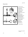
Parts and Controls
1 Fuel pump
3
7
6
2 Carburetor adjusting screw
3 Spark plug boot
4
1
4 Starter grip
2
8
5 Muffler (with spark arresting
screen) 1)
6 Throttle trigger
5
9
11
20
7 Slide control
15
13
8 Throttle trigger interlock
9 Bike handle
14
12
10 Handle support
11 Carrying eye*
12 Throttle cable retainer
16
10
#
13 Choke lever
14 Air filter cover
17
15 Fuel filler cap
18
19
11
21
17 Machine support
8
18 Loop handle
19 Barrier bar 1)
6
233BA042 KN
20
16 Fuel tank
20 Drive tube
21 Stop switch
#
Machine number
1) country specific depending on
version
FS 55
41
English / USA
Definitions
1.
Fuel pump.
Provides additional fuel feed for a
cold start.
8. Throttle trigger interlock.
Must be depressed before the
throttle trigger can be activated.
2.
Carburetor adjusting screw.
For tuning carburetor.
3.
Spark plug boot.
Connects the spark plug to the
ignition wire.
9. Bike handle.
To hold the brushcutter with both
hands.
4.
5.
Starter grip.
The grip of the pull starter, which is
the device to start the engine.
Muffler
(with spark arresting screen).
Attenuates exhaust noises and
diverts exhaust gases away from
operator.
6.
Throttle trigger.
Controls the speed of the engine.
7.
Slide control / Stop switch.
Starting throttle lock and stop
switch. Keeps the throttle partially
open during starting and switches
the engine's ignition off and stops
the running engine.
42
10. Handle support.
Connects the drive shaft to the
handle bars.
11. Carrying eye.
The device to connect the
brushcutter to the harness.
12. Throttle cable retainer.
Fixes the throttle cable on the drive
shaft.
13. Choke lever.
Eases engine starting by enriching
mixture.
16. Fuel tank.
For fuel and oil mixture.
17. Machine support.
For resting machine on the ground.
18. Loop handle.
For easy control of machine during
cutting work.
19. Barrier bar.
Helps keep cutting attachment away
from operator's feet and legs.
20. Drive tube.
Device to connect the engine with
the gearbox.
21. Stop switch.
Switches the engine's ignition
system off and stops the running
engine.
14. Air filter cover.
Covers the air filter element.
15. Fuel filler cap.
For closing the fuel tank.
FS 55
English / USA
Specifications
2
1
Definitions
EPA / CEPA:
1.
Mowing head
The cutting attachment, i. e. mowing
head, for different purposes
(special accessory).
2.
Deflector
The deflector is designed to reduce
the risk of injury from foreign objects
flung backwards toward the
operator by the cutting tool and from
contact with the cutting tool.
The Emission Compliance Period
referred to on the Emissions
Compliance Label indicates the number
of operating hours for which the engine
has been shown to meet Federal
emission requirements.
3
3.
5
4
4.
1
1 = Mowing head
2 = Deflector
(for mowing heads only)
3 = Line limiting blade
4 = Deflector with skirt
(for all cutting tools)
5 = Skirt
6 = Metal mowing tool
FS 55
4
002BA114 KN
6
3
Line limiting blade
Metal blade at the deflector in order
to keep the line of the mowing head
at the proper length.
Deflector with skirt
The deflector is designed to reduce
the risk of injury from foreign objects
flung backwards toward the
operator by the cutting tool and from
contact with the cutting tool. Is not
designed to contain fragmented
metal blades.
5.
Skirt
The skirt at the bottom of the
deflector must be adjusted as
described in the chapters on
mounting the various cutting tools.
6.
Metal mowing tool
The cutting attachment, i. e. blade,
made from metal for different
purposes (special accessory).
Category
A = 300 hours,
B = 125 hours,
C = 50 hours
CARB:
The Emission Compliance Period used
on the CARB Air Index Label indicates
the terms:
Extended = 300 hours
Intermediate = 125 hours
Moderate = 50 hours
Engine
Single cylinder two-stroke engine
Displacement:
1.66 cu.in
(27.2cm3)
Bore:
1.34 in (34 mm)
Stroke:
1.18 in (30 mm)
Engine power to
ISO 8893:
1 bhp (0.75 kW)
Idle speed:
2,800 rpm
Max. engine speed: 9,500 rpm
Max. output shaft
speed (cutting tool) 7,700 rpm
43
English / USA
Special Accessories
Ignition System
Weights
Type: Electronic magneto ignition
without cutting tool and deflector
FS 55 1)
11.0 lb (5.0 kg)
FS 55 R
10.6 lb (4.8 kg)
1) 2)
FS 55
11.2 lb (5.1 kg)
FS 55 R 2)
10.8 lb (4.9 kg)
Spark plug
(suppressed):
Electrode gap:
Spark plug thread:
Bosch WSR 6 F,
NGK BPMR 7 A
0.02 in (0.5 mm)
M 14 x 1.25;
0.37 in long
(9.5 mm)
Contact your STIHL dealer for
information regarding special
accessories that may be available for
your product.
1)
2)
Version with bike handle
Version with catalytic converter
R Version with loope handle
Versions with ErgoStart
Fuel System
Carburetor: All position diaphragm
carburetor with integral fuel pump
Air filter:
Fuel tank capacity:
Fuel mix:
44
Felt element
11.2 oz.
(0.33 l)
see “Fuel”
without cutting tool and deflector
11.5 lb (5.2 kg)
FS 55 C 1)
FS 55 RC
11.0 lb (5.0 kg)
FS 55 C 1) 2)
11.7 lb (5.3 kg)
FS 55 RC 2)
11.2 lb (5.1 kg)
1)
2)
Version with bike handle
Version with catalytic converter
R Version with loope handle
FS 55
English / USA
Maintenance and Repairs
Users of this unit should carry out only
the maintenance operations described
in this manual. Other repair work may be
performed only by authorized STIHL
service shops.
Warranty claims following repairs can be
accepted only if the repair has been
performed by an authorized STIHL
servicing dealer using original STIHL
replacement parts.
Original STlHL parts can be identified by
the STlHL part number, the STIHl
logo and, in some cases, by the STlHL
parts symbol (. This symbol may
appear alone on small parts.
FS 55
45
English / USA
Not for California:
STIHL Incorporated Federal Emission Control Warranty
Statement
Your Warranty Rights and
Obligations
Manufacturer's Warranty
Coverage:
The U.S. Environmental Protection
Agency (EPA) and STIHL Incorporated
are pleased to explain the Emission
Control System Warranty on your equipment type engine. In the U.S. new 1997
and later model year small off-road
equipment engines must be designed,
built and equipped, at the time of sale, to
meet the U.S. EPA regulations for small
non road engines. The equipment
engine must be free from defects in
materials and workmanship which
cause it to fail to conform with U.S. EPA
standards for the first two years of
engine use from the date of sale to the
ultimate purchaser.
In the U.S., 1997 and later model year
small off-road equipment engines are
warranted for two years. If any emissionrelated part on your engine is defective,
the part will be repaired or replaced by
STIHL Incorporated free of charge.
STIHL Incorporated must warrant the
emission control system on your small
off-road engine for the period of time
listed below provided there has been no
abuse, neglect or improper maintenance
of your small off-road equipment engine.
Your emission control system includes
parts such as the carburetor and the
ignition system. Also included may be
hoses, and connectors and other
emission related assemblies.
Where a warrantable condition exists,
STIHL Incorporated will repair your
small off-road equipment engine at no
cost to you, including diagnosis (if the
diagnostic work is performed at an
authorized dealer), parts, and labor.
46
Owner's Warranty
Responsibilities:
As the small off-road equipment engine
owner, you are responsible for the
performance of the required maintenance listed in your owner's manual.
STIHL Incorporated recommends that
you retain all receipts covering
maintenance on your small off-road
equipment engine, but STIHL
Incorporated cannot deny warranty
solely for the lack of receipts or for your
failure to ensure the performance of all
scheduled maintenance.
Any replacement part or service that is
equivalent in performance and durability
may be used in non-warranty
maintenance or repairs, and shall not
reduce the warranty obligations of the
engine manufacturer.
As the small off-road equipment engine
owner, you should be aware, however,
that STIHL Incorporated may deny you
warranty coverage if your small off-road
equipment engine or a part has failed
due to abuse, neglect, improper maintenance or unapproved modifications.
You are responsible for presenting your
small off-road equipment engine to a
STIHL service center as soon as a
problem exists. The warranty repairs will
be completed in a reasonable amount of
time, not to exceed 30 days.
If you have any questions regarding your
warranty rights and responsibilities,
please contact a STIHL customer
service representative at 1-800-4678445 or you can write to
STIHL Inc.,
536 Viking Drive, P.O. Box 2015,
Virginia Beach, VA 23450-2015.
Coverage by STIHL Incorporated
STIHL Incorporated warrants to the
ultimate purchaser and each subsequent purchaser that your small off-road
equipment engine will be designed, built
and equipped, at the time of sale, to
meet all applicable regulations. STIHL
Incorporated also warrants to the initial
purchaser and each subsequent
purchaser that your engine is free from
defects in materials and workmanship
which cause the engine to fail to conform
with applicable regulations for a period
of two years.
Warranty Period
The warranty period will begin on the
date the utility equipment engine is
purchased by the initial purchaser and
you have signed and sent back the
warranty card to STIHL.
FS 55
English / USA
If any emission related part on your
engine is defective, the part will be
replaced by STIHL Incorporated at no
cost to the owner. Any warranted part
which is not scheduled for replacement
as required maintenance, or which is
scheduled only for regular inspection to
the effect of "repair or replace as
necessary" will be warranted for the
warranty period. Any warranted part
which is scheduled for replacement as
required maintenance will be warranted
for the period of time up to the first
scheduled replacement point for that
part.
Diagnosis
You, as the owner, shall not be charged
for diagnostic labor which leads to the
determination that a warranted part is
defective. However, if you claim
warranty for a component and the
machine is tested as non-defective,
STIHL Incorporated will charge you for
the cost of the emission test. Mechanical
diagnostic work will be performed at an
authorized STIHL servicing dealer.
Emission test may be performed either
at STIHL Incorporated or at any
independent test laboratory.
Warranty Work
STIHL Incorporated shall remedy
warranty defects at any authorized
STIHL servicing dealer or warranty
station. Any such work shall be free of
charge to the owner if it is determined
that a warranted part is defective.
FS 55
Any manufacturer-approved or
equivalent replacement part may be
used for any warranty maintenance or
repairs on emission-related parts and
must be provided without charge to the
owner. STIHL Incorporated is liable for
damages to other engine components
caused by the failure of a warranted part
still under warranty.
Limitations
This Emission Control Systems
Warranty shall not cover any of the
following:
:
repair or replacement required
because of misuse, neglect or lack
of required maintenance,
:
repairs improperly performed or
replacements not conforming to
STIHL Incorporated specifications
that adversely affect performance
and/or durability, and alterations or
modifications not recommended or
approved in writing by STIHL
Incorporated,
The following list specifically defines the
emission-related warranted parts:
Carburetor
Choke (Cold start enrichment system)
Intake manifold
Air filter
Spark plug
Magneto or electronic ignition system
(ignition module)
Catalytic converter (if applicable)
Fasteners
Where to make a claim for
Warranty Service
and
:
replacement of parts and other
services and adjustments
necessary for required maintenance
at and after the first scheduled
replacement point.
Bring the product to any authorized
STIHL servicing dealer and present the
signed warranty card.
Maintenance Requirements
The maintenance instructions in this
manual are based on the application of
the recommended 2-stroke fuel-oil
mixture (see also instruction "Fuel").
Deviations from this recommendation
regarding quality and mixing ratio of fuel
and oil may require shorter maintenance
intervals.
47
English / USA
For California only:
STIHL Incorporated California Exhaust and Evaporative Emissions Control Warranty
Statement
Your Warranty Rights and
Obligations
Manufacturer’s Warranty
Coverage:
The California Air Resources Board
(CARB) and STIHL Incorporated are
pleased to explain the emissions control
system's warranty on your 2007 and
later small off-road equipment engine.
This emissions control system is
warranted for two years in California. If
any emissions-related part on your
equipment is defective, the part will be
repaired or replaced by STIHL
Incorporated free of charge.
In California, new equipment that uses
small off-road-engines must be
designed, built, and equipped to meet
the State's stringent anti-smog
standards. STIHL Incorporated must
warrant the emissions control system on
your small off-road engine for the period
listed below provided there has been no
abuse, neglect or improper maintenance
of your small off-road engine.
Your emissions control system may
include parts such as:
Air filter, Carburetor, Purger, Choke
(Cold Start Enrichment System), Control
Linkages, Intake Manifold, Magneto or
Electronic Ignition System (Ignition
module), Spark Plug, Catalytic
Converter (if applicable), Fuel Tank, Fuel
Cap, Fuel Line, Fuel Line Fittings,
Clamps, Fasteners.
Where a warrantable condition exists,
STIHL Incorporated will repair your
small off-road equipment engine at no
cost to you including diagnosis, parts
and labor.
48
Owner’s Warranty
Responsabilities:
As the small off-road equipment engine
owner, you are responsible for
performance of the required
maintenance listed in your instruction
manual. STIHL Incorporated
recommends that you retain all receipts
covering maintenance on your small offroad equipment engine, but STIHL
Incorporated cannot deny warranty
solely for the lack of receipts or your
failure to ensure the performance of all
scheduled maintenance.
As the small off-road equipment engine
owner, you should however be aware
that STIHL Incorporated may deny you
warranty coverage if your small off-road
equipment engine or a part has failed
due to abuse, neglect, or improper
maintenance or unapproved
modifications.
You are responsible for presenting your
small off-road equipment engine to a
STIHL servicing dealer as soon as the
problem exists. The warranty repairs
should be completed in a reasonable
amount of time, not to exceed 30 days. If
you have any questions regarding your
warranty rights and responsibilities,
please contact a STIHL customer
service representative at 1-800-4678445 or you can write to
STIHL Inc., 536 Viking Drive,
P.O. Box 2015,
Virginia Beach, VA 23450-2015.
Coverage by STIHL Incorporated
STIHL Incorporated warrants to the
ultimate purchaser and each
subsequent purchaser that your small
off-road equipment engine is designed,
built and equipped, at the time of sale, to
meet all applicable emission
regulations.
STIHL Incorporated also warrants to the
initial purchaser and each subsequent
purchaser that your engine is free from
defects in materials and workmanship
which cause the engine to fail to conform
to applicable emission regulations for a
period of two years.
FS 55
English / USA
Defects Warranty Period
The warranty periods will begin on the
date the utility equipment engine is
purchased by the initial purchaser. If any
emission related part on your engine is
defective, the part will be replaced by
STIHL Incorporated at no cost to the
owner.
Add on or modified parts that are not
exempted by CARB may not be used.
The use of any non exempted add on or
modified parts will be grounds for
disallowing a warranty claim. STIHL
Incorporated will not be liable to warrant
failures of warranted parts caused by the
use of a non exempted add on or
modified part.
The warranty on emissions-related parts
will be interpreted as follows:
1. Any warranted part that is not
scheduled for replacement as required
maintenance in the written instructions
required in the Emission Warranty Parts
List (see below) must be warranted for
the warranty period defined in
Subsection COVERAGE BY STIHL
INCORPORATED, see above. If any
such part fails during the period of
warranty coverage, it must be repaired
or replaced by the manufacturer
according to Subsection (4) below. Any
such part repaired or replaced under the
warranty must be warranted for the
remaining warranty period.
FS 55
2. Any warranted part that is
scheduled only for regular inspection in
the written instructions required by the
Emission Warranty Parts List (see
below) must be warranted for the
warranty period defined in Subsection
COVERAGE BY STIHL
INCORPORATED, see above. A
statement in such written instructions to
the effect of "repair or replace as
necessary" will not reduce the period of
warranty coverage. Any such part
repaired or replaced under warranty
must be warranted for the remaining
warranty period.
5. Notwithstanding the provisions of
Subsection (4) above, warranty services
or repairs will be provided at all
manufacturer distribution centers that
are authorized to service the subject
engines.
3. Any warranted part that is
scheduled for replacement as required
maintenance in the written instructions
required by the Emission Warranty Parts
List (see below) must be warranted for
the period of time prior to the first
scheduled replacement point for that
part. If the part fails prior to the first
scheduled replacement, the part must
be repaired or replaced by the engine
manufacturer according to Subsection
(4) below. Any such part repaired or
replaced under warranty must be
warranted for the remainder of the
period prior to the first scheduled
replacement point for the part.
Warranty Work
4. Repair or replacement of any
warranted part under the warranty must
be performed at a warranty station at no
charge to the owner.
6. The owner must not be charged for
diagnostic labor that leads to the
determination that a warranted part is in
fact defective, provided that such
diagnostic work is performed at a
warranty station.
STIHL Incorporated shall remedy
warranty defects at any authorized
STIHL servicing dealer or warranty
station. Any such work shall be free of
charge to the owner if it is determined
that a warranted part is defective. Any
manufacturer approved or equivalent
replacement part may be used for any
warranty maintenance or repairs on
emission related parts and must be
provided without charge to the owner.
STIHL Incorporated is liable for
damages to other engine components
caused by the failure of a warranted part
still under warranty.
49
English / USA
Trademarks
Emission Warranty Parts List
STIHL Registered Trademarks
Air filter, Carburetor, Purger, Choke
(Cold Start Enrichment System), Control
Linkages, Intake Manifold, Magneto or
Electronic Ignition System (Ignition
Module), Spark Plug, Catalytic
Converter (if applicable), Fuel Tank, Fuel
Cap, Fuel Line, Fuel Line Fittings,
Clamps, Fasteners
STIHL®
Where to make a claim for
Warranty Service
AUTOCUT®
Bring the STIHL product to any
authorized STIHL servicing dealer and
present the signed STIHL product
registration card, or the print-out of the
electronic product registration.
OILOMATIC®
Limitations
The repair or replacement of any
warranted part otherwise eligible for
warranty coverage may be excluded
from such warranty coverage if STIHL
Incorporated demonstrates that the
STIHL product has been abused,
neglected, or improperly maintained,
and that such abuse, neglect, or
improper maintenance was the direct
cause of the need for repair or
replacement of the part. That
notwithstanding, any adjustment of a
component that has a factory installed,
and properly operating, adjustment
limiting device is still eligible for warranty
coverage.
50
Some of STIHL’s Common Law
Trademarks
q
(
The color combination orange-grey
(U.S. Registrations #2,821,860;
#3,010,057; and #3,010,058)
4-MIX®
EASYSTART®
STIHL Cutquik®
STIHL DUROMATIC®
STIHL Farm Boss®
STIHL Quickstop®
STIHL ROLLOMATIC®
STIHL WOOD BOSS®
TIMBERSPORTS®
YARD BOSS®
BioPlus™
Easy2Start™
EasySpool™
ElastoStart™
Ematic™ / Stihl-E-Matic™
FixCut™
HT Plus™
IntelliCarb™
Master Control Lever™
Micro™
Pro Mark™
Quad Power™
Quiet Line™
STIHL Arctic™
STIHL Compact™
STIHL HomeScaper Series™
STIHL Interchangeable Attachment
Series™
FS 55
English / USA
STIHL Magnum™ / Stihl-Magnum™
STIHL MiniBoss™
STIHL MotoPlus 4™
STIHL Multi-Cut HomeScaper Series™
Stihl Outfitters™
STIHL PICCO™
STIHL PolyCut™
STIHL PowerSweep™
STIHL Precision Series™
STIHL Protech™
STIHL RAPID™
STIHL SuperCut™
STIHL Territory™
TapAction™
TrimCut™
This listing of trademarks is subject to
change.
Any unauthorized use of these
trademarks without the express written
consent of
ANDREAS STIHL AG & Co. KG,
Waiblingen is strictly prohibited.
FS 55
51
English / USA
52
FS 55
español / EE.UU
© ANDREAS STIHL AG & Co. KG, 2007
0458 233 8621 C. M16. H7. CP. Printed in USA
Impreso en papel sin cloro.
Las tintas contienen aceites vegetales,el papel es reciclable.
BA_SE_012_006_31_12.fm
Contenido
Guía para el uso
de este manual ...............................
Medidas de seguridad y
técnicas de manejo ........................
Combinaciones aprobadas
de herramienta de corte,
deflector, mango y arnés ................
Montaje del manillar de
bicicleta ...........................................
Montaje del mango tórico ...............
Colocación de la argolla
de transporte ..................................
Montaje del deflector ......................
Montaje de las herramientas
de corte ..........................................
Combustible ...................................
Llenado
de combustible ...............................
Colocación del arnés ......................
Equilibrio de la cortadora
de matorrales .................................
Arranque / parada ...........................
Instrucciones de manejo ................
Limpieza del filtro de aire ...............
Manejo del motor ............................
Ajuste del carburador .....................
Revisión de la bujía ........................
STIHl
FS 55
54
55
68
70
71
72
73
73
78
79
79
80
81
85
85
86
86
88
Arrancador de cuerda .................... 89
Almacenamiento
de la máquina ................................. 89
Lubricación
de la caja de engranajes ................ 89
Afilado de las herramientas
de corte metálicas .......................... 90
Inspecciones y mantenimiento
por el centro de servicio STIHL ...... 91
Tabla de mantenimiento ................. 92
Piezas y controles .......................... 93
Especificaciones ............................ 95
Accesorios especiales .................... 96
Mantenimiento y
reparaciones .................................. 97
Declaración de garantía de
STIHL Incorporated sobre
sistemas de control de emisiones
según normas Federales ............... 98
Declaración de garantía de
STIHL Incorporated sobre
el control de emisiones de gases
de escape y emisiones por
evaporación para
el Estado de California ................. 100
Marcas comerciales ..................... 102
Permita que solamente las personas
que comprenden la materia tratada en
este manual manejen su orilladora/
cortadora de matorrales. Para obtener el
rendimiento y satisfacción máximos de
la orilladora/cortadora de matorrales
STIHL, es importante leer y comprender
las instrucciones de mantenimiento y las
precauciones de seguridad, que
empiezan en la página 55, antes de usar
la orilladora/cortadora de matorrales.
Comuníquese con el concesionario o
distribuidor de STIHL si no se entiende
alguna de las instrucciones dadas en el
presente manual.
!Advertencia!
Dado que la orilladora/cortadora de
matorrales es una herramienta de corte
motorizada de gran velocidad, es
necesario tomar medidas especiales de
seguridad para reducir el riesgo de
lesiones. El uso descuidado o
inadecuado puede causar lesiones
graves e incluso mortales. Asegúrese
que su máquina esté equipada con el
deflector, mango y arnés adecuados
para el tipo de accesorio de corte que se
está utilizando. La filosofía de STIHL es
mejorar continuamente todos sus
productos. Como resultado, de vez en
cuando se llevan a cabo modificaciones
y mejoramientos técnicos. Si las
características de funcionamiento o la
apariencia de su orilladora/cortadora de
matorrales difieren de aquéllas descritas
en este manual, le rogamos ponerse en
contacto con el concesionario STIHL
para recibir más información y
asistencia.
53
español / EE.UU
Guía para el uso de este
manual
Pictogramas
Todos los pictogramas que se
encuentran en la máquina se muestran
y explican en este manual.
Las instrucciones de uso y manipulación
vienen acompañadas de ilustraciones.
Símbolos en el texto
Los pasos individuales o procedimientos
descritos en el manual pueden estar
señalados en diferentes maneras:
:
Un punto identifica un paso o
procedimiento sin referencia directa
a una ilustración.
Una descripción de un paso o
procedimiento que se refiere
directamente a una ilustración puede
tener números de referencia que
aparecen en la ilustración.
Ejemplo:
Suelte el tornillo (1)
Palanca (2) ...
Además de las instrucciones de uso, en
este manual pueden encontrarse
párrafos a los que usted debe prestar
atención especial. Tales párrafos están
marcados con los símbolos que se
describen a continuación.
Advertencia donde existe el riesgo
de un accidente o lesiones
personales o daños graves a la
propiedad.
Precaución donde existe el riesgo
de dañar la máquina o los
componentes individuales.
Nota o sugerencia que no es
esencial para el uso de la máquina,
pero puede ayudar al operador a
comprender mejor la situación y
mejorar su manera de manejar la
máquina.
Nota o sugerencia sobre el
procedimiento correcto con el fin de
evitar dañar el medio ambiente.
Equipo y características
Este manual de instrucciones
puede describir varios modelos con
diferentes características. Los
componentes que no se encuentran
instalados en todos los modelos y
las aplicaciones correspondientes
están marcados con un asterisco
(*). Esos componentes pueden ser
ofrecidos como accesorios
especiales por el concesionario
STIHL.
Mejoramientos técnicos
La filosofía de STIHL es mejorar
continuamente todos su productos.
Como resultado de ello, periódicamente
se introducen cambios de diseño y
mejoras. Si las características de
funcionamiento o la apariencia de su
máquina difieren de las descritas en
este manual, comuníquese con el
concesionario STIHL para obtener la
ayuda que requiera.
Por lo tanto, es posible que algunos
cambios, modificaciones y
mejoramientos no hayan sido descritos
en este manual.
54
FS 55
español / EE.UU
Medidas de seguridad y
técnicas de manejo
Advertencia
Dado que la cortadora de
matorrales es una herramienta de corte motorizada que funciona a gran
velocidad, es necesario tomar medidas
especiales de seguridad para reducir el
riesgo de lesiones.
Es importante que usted
lea, comprenda bien y
respete las siguientes
advertencias y medidas
de seguridad. Lea el
manual del usuario y las
instrucciones de seguridad periódicamente. El uso descuidado o inadecuado
de cualquier cortadora de matorrales
puede causar lesiones graves e incluso
mortales.
Pida a su concesionario STIHL que le
enseñe el manejo de la cortadora de
matorrales. Respete todas las disposiciones, reglamentos y normas de seguridad locales del caso.
!Advertencia
No preste ni alquile nunca su cortadora
de matorrales sin el manual del usuario.
Asegúrese que todas las personas que
utilicen la cortadora de matorrales lean y
comprendan la información contenida
en este manual.
FS 55
!Advertencia
El uso de cualquier cortadora de matorrales puede ser peligroso. Si la herramienta de corte giratoria llega a quedar
en contacto con su cuerpo, le ocasionará una cortadura. Cuando choca con
algún objeto extraño sólido tal como
rocas o pedazos de metal, puede arrojarlo directamente o por rebote en dirección de personas que se encuentren en
la cercanía o del operador.
El contacto con dichos objetos puede
dañar los accesorios de corte y puede
hacer que las cuchillas se rompan, astillen o agrieten.
STIHL no recomienda el uso de cuchillas rígidas en zonas pedregosas. Los
objetos arrojados o las cuchillas dañadas pueden provocar lesiones graves o
mortales al operador o a personas que
se encuentren en su proximidad.
!Advertencia
Nunca se debe permitir a los niños que
usen una cortadora de matorrales. No
se debe permitir la proximidad de otros,
especialmente niños y animales, donde
se esté utilizando la cortadora de matorrales.
Nunca deje la cortadora de matorrales
funcionando sin vigilancia.
La mayoría de las medidas de seguridad
y avisos contenidos en este manual se
refieren al uso de todas las cortadoras
de matorrales de STIHL. Los distintos
modelos pueden contar con piezas y
controles diferentes. Vea la sección
correspondiente de su manual del usuario para tener una descripción de los
controles y la función de cada componente de su modelo de cortadora de
matorrales.
El uso seguro de una cortadora de
matorrales atañe a
1.
2.
3.
el operador
la cortadora de matorrales
el uso de la cortadora de matorrales.
EL OPERADOR
Condición física
Usted debe estar en buenas condiciones físicas y psíquicas y no encontrarse
bajo la influencia de ninguna sustancia
(drogas, alcohol, etc.) que le pueda restar visibilidad, destreza o juicio. No
maneje la cortadora de matorrales
cuando está fatigado.
Esté alerta. Si se cansa durante el
manejo de su cortadora de matorrales,
tómese un descanso. El cansancio
puede provocar una pérdida del control.
El uso de cualquier cortadora de matorrales es fatigoso. Si usted padece de
alguna dolencia que pueda ser agravada por la fatiga, consulte a su médico
antes de utilizar la cortadora de matorrales.
55
español / EE.UU
!Advertencia
–
El uso prolongado de una cortadora de
matorrales (u otras máquinas) expone al
operador a vibraciones que pueden provocar el fenómeno de Raynaud (dedos
blancos) o el síndrome del túnel del carpio.
Estas condiciones reducen la capacidad
manual de sentir y regular la temperatura, producen entumecimiento y ardor y
pueden provocar trastornos nerviosos y
circulatorios, así como necrosis de los
tejidos.
No se conocen todos los factores que
contribuyen a la enfermedad de Raynaud, pero el clima frío, el fumar y las
enfermedades o condiciones físicas que
afectan los vasos sanguíneos y la circulación de la sangre, como asimismo los
niveles altos de vibración y períodos
prolongados de exposición a la vibración son mencionados como factores en
el desarrollo de la enfermedad de Raynaud. Por lo tanto, para reducir el riesgo
de la enfermedad de dedos blancos y
del síndrome del túnel del carpio, sírvase notar lo siguiente:
56
La mayor parte de las herramientas
motorizadas de STIHL se ofrecen
con un sistema antivibración ("AV")
cuyo propósito es reducir la transmisión de las vibraciones creadas por
el motor a las manos del operador.
Se recomienda el uso del sistema
AV a aquellas personas que utilizan
herramientas motorizadas en forma
constante y regular.
–
Use guantes y mantenga las manos
abrigadas.
–
Mantenga el sistema AV en buen
estado. Una cortadora de matorrales con componentes flojos o con
amortiguadores AV dañados o desgastados también tendrá tendencia
a tener niveles más altos de vibración.
–
Agarre firmemente los mangos en
todo momento, pero no los apriete
con fuerza constante y excesiva;
tómese descansos frecuentes.
Todas las precauciones antes mencionadas no le garantizan que va a estar
totalmente protegido contra la enfermedad de Raynaud o el síndrome del túnel
del carpio. Por lo tanto, los operadores
constantes y regulares deben controlar
con frecuencia el estado de sus manos
y dedos. Si aparece alguno de los síntomas arriba mencionados, consulte
inmediatamente al médico.
!Advertencia
El sistema de encendido de la máquina
STIHL produce un campo electromagnético de intensidad muy baja. El mismo
puede interferir con algunos tipos de
marcapasos. Para reducir el riesgo de
lesiones graves o mortales, las personas portadoras de marcapasos deben
consultar a sus médicos y al fabricante
del marcapasos antes de usar esta
máquina.
Vestimenta adecuada
!Advertencia
Para reducir el riesgo de lesiones el
operador debe usar el equipo protector
adecuado." El deflector provisto con su
cortadora de matorrales no siempre protege al operador contra todos los objetos extraños (gravilla, vidrio, alambre,
etc.) arrojados por el accesorio de corte
giratorio. Los objetos arrojados o lanzados por el accesorio también pueden
rebotar y golpear al operador.
FS 55
español / EE.UU
!Advertencia
Para reducir el riesgo de
lesionarse los ojos, nunca
maneje la cortadora de
matorrales si no tiene
puestas gafas o anteojos
de seguridad bien ajustados con una protección adecuada en las
partes superior y laterales que satisfagan la norma ANSI Z 87.1 (o la norma
nacional correspondiente). Para reducir
el riesgo de lesionarse la cara, STIHL
recomienda usar también una careta o
protector facial adecuado sobre las
gafas o anteojos de seguridad.
!Advertencia
El ruido de la cortadora de
matorrales puede dañar
los oídos. Siempre use
amortiguadores del ruido
(tapones u orejeras) para
protegerse los oídos. Los
usuarios constantes y regulares deben
someterse con frecuencia a un examen
o control auditivo.
Protéjase las manos con
guantes cuando manipule
la cortadora de matorrales y la herramienta de
corte. Los guantes gruesos y antideslizantes
mejoran el manejo y protegen las manos.
FS 55
La ropa debe ser de confección fuerte y ajustada,
pero no tanto que impida
la completa libertad de
movimiento. Evite el uso
de chaquetas sueltas,
bufandas, corbatas, joyas, pantalones
acampanados o con vueltas, pelo largo
suelto o cualquier cosa que pueda
engancharse en las ramas, matorrales o
piezas en movimiento de la máquina.
Use pantalones largos hechos de un
material grueso para protegerse las
piernas. No use pantalones cortos, sandalias o pies descalzos. Sujétese el pelo
de modo que quede sobre los hombros.
Una buena base de
apoyo es indispensable
cuando se maneja la cortadora de matorrales.
Póngase botas gruesas
con suela antideslizante.
Recomendamos las botas de seguridad
con puntera de acero.
LA CORTADORA DE MATORRALES
Para las ilustraciones y definiciones de
los componentes de la cortadora de
matorrales, vea el capítulo "Piezas y
controles".
!Advertencia
Nunca modifique, de ninguna manera,
una cortadora de matorrales. Utilice únicamente los accesorios y repuestos
suministrados por STIHL o expresamente autorizados por STIHL para
usarse con los modelos específicos de
cortadoras de matorrales de STIHL. Si
bien es posible conectar a la cortadora
de matorrales de STIHL ciertos accesorios no autorizados, su uso puede ser,
en la práctica, extremadamente peligroso.
Utilice un casco de seguridad aprobado para reducir el riesgo de lesionarse
la cabeza en caso de
existir tal tipo de peligro.
57
español / EE.UU
USO DE LA CORTADORA DE
MATORRALES
Llenado de combustible
A
Transporte de la cortadora de matorrales
Preparación para el uso de la cortadora de matorrales
Ajuste el arnés y la empuñadura de
modo correspondiente a su estatura
antes de empezar a trabajar. La
máquina debe estar correctamente
equilibrada de la forma especificada en
el manual del operador para un control
correcto y menos fatiga de trabajo.
Compruebe siempre la condición y funcionamiento de su cortadora de matorrales antes de ponerla en marcha,
especialmente el gatillo de aceleración,
el bloqueo del gatillo de aceleración (si
lo tiene), el interruptor de parada, la
herramienta de corte, el deflector y el
arnés.
58
B
000BA007 KN
Siempre apague el motor y asegúrese
de que el accesorio de corte esté detenido antes de apoyar la cortadora de
matorrales en el suelo. Cuando transporte la cortadora de matorrales en un
vehículo, sujétela firmemente para
impedir su volcadura, el derrame de
combustible y el daño a la cortadora.
Mantenga las herramientas de corte
metálicas cubiertas con el protector para
el transporte (accesorio opcional).
000BA006 KN
!Advertencia
Las flechas (A) en el deflector y el tope
(B) muestran el sentido correcto de rotación de la herramienta de corte.
El gatillo acelerador deberá moverse
libremente y siempre regresar a la posición de ralentí. La herramienta de corte
debe estar correctamente apretada y en
buenas condiciones de trabajo. Busque
piezas sueltas (tuercas, tornillos, etc.) y
cuchillas agrietadas, dobladas, deformadas o dañadas.
La cortadora de matorrales de STIHL
utiliza una mezcla de aceite-gasolina
como combustible (vea el capítulo
"Combustible" en el manual del usuario).
!Advertencia
La gasolina es un combustible muy inflamable.
Si se derrama y arde a
causa de una chispa u
otra fuente de ignición,
puede provocar un incendio y quemaduras graves o daños a la
propiedad. Tenga sumo cuidado cuando
manipule gasolina o la mezcla de combustible.
No fume cerca del combustible, ni acerque ningún fuego o llama a la cortadora
de matorrales.
Instrucciones para el llenado de combustible
!Advertencia
Cargue de combustible su cortadora de
matorrales en lugares al aire libre bien
ventilados. Siempre apague el motor y
deje que se enfríe antes de llenar de
combustible. Dependiendo del combustible utilizado, de las condiciones climáticas y del sistema de ventilación del
tanque, es posible que se forme vapor
de gasolina a presión dentro del tanque
de gasolina de los motores de dos tiempos.
FS 55
español / EE.UU
Para reducir el riesgo de quemaduras,
así como otras lesiones corporales ocasionadas por los escapes de vapor de
gasolina y otras emanaciones, quite la
tapa de llenado de combustible de la
cortadora de matorrales cuidadosamente de modo que la presión que se
pueda haber acumulado en el tanque se
disipe lentamente. Nunca quite la tapa
de llenado de combustible mientras el
motor está funcionando.
Elija una superficie despejada para llenar el tanque y aléjese 3 m (10 pies) por
lo menos del lugar en que lo haya llenado antes de arrancar el motor. Limpie
los derrames de combustible antes de
arrancar la cortadora de matorrales y
compruebe que no existen fugas.
!Advertencia
Compruebe que no existen fugas de
combustible mientras llena el tanque y
durante el funcionamiento de la
máquina. Si detecta alguna fuga de
combustible o aceite, no arranque el
motor ni lo haga funcionar sin antes
reparar la fuga y limpiar el combustible
derramado. Tenga cuidado de no mancharse la ropa con combustible. Si la
mancha, cámbiesela inmediatamente.
La tapa de llenado de combustible
puede diferir en los distintos modelos.
Tapa con mango
Tapa de llenado atornillable
!Advertencia
!Advertencia
Para reducir el riesgo de que ocurran
incendios y fugas de combustible debido
a una tapa de llenado mal apretada, es
necesario insertarla correctamente en la
boca de llenado y apretarla bien firme.
Las vibraciones de la
máquina pueden aflojar
una tapa de combustible
que ha quedado mal
apretada, o simplemente
soltarla y derramar combustible. Para reducir el riesgo de derrames e incendio, apriete la tapa de llenado de combustible a mano con la
mayor fuerza posible.
Levante el mango situado
encima de la tapa de
llenado STIHL de modo
que quede en posición
vertical. Inserte la tapa de
modo que la marca
triangular en el mango coincida con
aquélla en la boca de llenado. Gire en
sentido horario el mango de la tapa
hasta donde tope (aprox. un cuarto de
vuelta).
Doble el mango hasta
dejarlo plano sobre la
tapa de llenado. La tapa
no está bien colocada si
el mango no queda a ras
con la tapa y la traba en el
mango no encaja en la cavidad
correspondiente en la boca de llenado.
En este caso, vuelva a colocar la tapa.
Instrucciones de manejo
! Advertencia
El uso indebido de
cualquier cortadora de matorrales
puede causar
lesiones graves o
mortales. Para reducir el riesgo de sufrir
lesiones corporales debido a la pérdida
de control y/o al contacto con la cuchilla
y objetos arrojados, asegúrese que su
máquina está equipada con el deflector,
mango y arnés correctos para el tipo de
accesorio de corte que está usando (vea
el capítulo "Combinaciones aprobadas
de la herramienta de corte, deflector,
mango y arnés").
Mantenga siempre el deflector (y la faldilla en su caso) bien ajustado (vea en
su manual del usuario el capítulo sobre
montaje de las diversas herramientas de
corte).
FS 55
59
español / EE.UU
Arranque
!Advertencia
Su cortadora de matorrales es una
máquina que debe ser manejada por
solamente una persona. Una vez que
está funcionando, puede arrojar objetos
extraños a gran distancia.
15m (50ft)
!Advertencia
Para reducir el riesgo de lesiones
debido a la pérdida de control, esté
absolutamente seguro que la herramienta de corte se encuentra lejos de su
cuerpo y de todas las obstrucciones y
objetos, incluido el suelo, porque al
arrancar el motor acelerado, su velocidad será lo suficientemente rápida para
que el embrague se engrane y haga
girar la herramienta de corte.
!Advertencia
Para reducir el riesgo de ocasionar
lesiones a los ojos u otras partes del
cuerpo, asegúrese que las personas
estén a por lo menos 15 m (50 pies) de
distancia de la máquina. Se debe aconsejar a las personas que se encuentran
cerca de la máquina a que usen protección de los ojos. Apague el motor y la
herramienta de corte inmediatamente si
se le aproxima alguna persona. Ponga
en marcha y maneje su cortadora de
matorrales sin ayuda de nadie. Para las
instrucciones específicas de arranque,
vea la sección correspondiente en el
manual del usuario. Coloque la cortadora de matorrales sobre suelo firme u
otra superficie sólida en un lugar abierto.
Mantenga buen equilibrio con los pies
bien apoyados.
60
Cuando tire del mango de arranque, no
enrolle la cuerda de arranque alrededor
de la mano. No permita que la manija
regrese abruptamente, sino guíe la
cuerda de arranque para que se enrolle
correctamente. Si no ejecuta este procedimiento puede lastimarse la mano o los
dedos y también dañar el mecanismo de
arranque.
Con el motor funcionando pero a velocidad de ralentí, enganche la cortadora de
matorrales al gancho de resorte de su
arnés (vea el capítulo correspondiente
en este manual).
Convertidor catalítico
!Advertencia
Algunos modelos de
cortadoras de matorrales
STIHL están equipados
con un convertidor
catalítico, el que está
diseñado para reducir las
emisiones de escape del motor
mediante un proceso químico en el
silenciador. Debido a este proceso, el
silenciador no se enfría tan rápidamente
como los del tipo convencional cuando
el motor regresa a ralentí o es apagado.
Para reducir el riesgo de incendio y de
lesiones por quemadura, es necesario
respetar las siguientes medidas de
seguridad específicas.
!Advertencia
Como un silenciador con convertidor
catalítico se enfría más lentamente que
los silenciadores convencionales, apoye
siempre su cortadora de matorrales en
posición vertical y no lo coloque nunca
donde el silenciador quede cerca de
material seco como por ejemplo
matorrales, pasto o virutas de madera, o
sobre otros materiales combustibles
mientras todavía está caliente.
FS 55
español / EE.UU
Deje que el motor se enfríe apoyado
sobre una superficie de hormigón,
metal, suelo raso o madera maciza (por
ej., el tronco de un árbol caído) lejos de
cualquier sustancia combustible.
!Advertencia
Para reducir el riesgo de incendio o
lesiones por quemadura, deje que la
máquina se enfríe antes de reabastecer
de combustible la cortadora de matorrales después de usarlo.
!Advertencia
Nunca desarme ni modifique el
silenciador. El silenciador podría
dañarse y causar el aumento de la
radiación de calor o chispas, aumentando así el riesgo de incendio o
lesiones por quemadura. Además, se
podría dañar permanentemente el
motor. Haga reparar el silenciador
únicamente por el concesionario de
servicio STIHL.
!Advertencia
Para reducir el riesgo de incendio o
lesiones por quemadura, mantenga
limpia la zona alrededor del silenciador.
Quite toda la basura tal como las agujas
de pinos, ramas u hojas.
FS 55
!Advertencia
Una caja de cilindro dañada o mal
instalada, o una envuelta del silenciador
dañada o deformada, puede perjudicar
el efecto de enfriamiento del convertidor
catalítico. Para reducir el riesgo de
incendio o lesiones por quemadura, no
continúe trabajando con una caja de
cilindro dañada o mal instalada, o una
envuelta del silenciador dañada o
deformada. El convertidor catalítico está
dotado de rejillas diseñadas para reducir
el riesgo de incendio debido a la emisión
de partículas calientes. Debido al calor
de la reacción catalítica, estas rejillas
normalmente permanecen limpias y no
necesitan servicio o mantenimiento. Si
el rendimiento de su máquina comienza
a disminuir y sospecha que las rejillas
están obstruidas, haga reparar el
silenciador por un concesionario de
servicio STIHL.
Condiciones de trabajo
Maneje y arranque su cortadora de
matorrales solamente al aire libre en un
lugar bien ventilado.
Maneje la cortadora de matorrales solamente en condiciones de buena visibilidad y a la luz del día. Trabaje con mucho
cuidado.
!Advertencia
Su cortadora de matorrales emite gases de
escape tóxicos apenas el
motor empieza a funcionar. Estos gases (por ej.,
monóxido de carbono)
pueden ser incoloros e inodoros. Para
reducir el riesgo de sufrir lesiones graves o mortales por respirar gases tóxicos, nunca haga funcionar la cortadora
de matorrales puertas adentro o en
lugares mal ventilados.
!Advertencia
El uso de este producto puede generar
polvo y vapores que contienen productos químicos considerados como causantes de enfermedades respiratorias,
cáncer, defectos de nacimiento u otra
toxicidad reproductora. Si usted desconoce los riesgos asociados con el polvo
o vapor en cuestión, consulte con su
empleador, autoridades gubernamentales tales como OSHA y NIOSH y otras
fuentes de información sobre materiales
peligrosos. Por ejemplo, el estado de
61
español / EE.UU
002BA024 LÄ
!Advertencia
El silenciador y otros componentes del
motor (por ej., aletas del cilindro, bujía)
se calientan durante el funcionamiento y
permanecen calientes por un buen rato
después de apagar el motor. Para reducir el riesgo de quemaduras, no toque el
silenciador y otros componentes mientras están calientes.
No corte ningún tipo de material que no
sea pasto, matorrales y madera. Las
herramientas de corte pueden usarse
solamente para las operaciones descritas en su manual.
002BA080 KN
002BA055 KN
Siempre que sea posible, controle el
polvo y los vapores en su punto de origen. Al respecto, emplee buenas prácticas de trabajo y siga las recomendaciones de OSHA/NIOSH y asociaciones
laborales y comerciales. Cuando sea
imposible eliminar la inhalación del
polvo o vapores tóxicos, el operador y
las personas que se encuentren en la
cercanía siempre deberán usar un respirador aprobado por NIOSH/MSHA para
el tipo de polvo y/o vapores presentes
en el lugar.
002BA054 KN
California y algunas otras autoridades
han publicado varias listas de sustancias carcinógenas, de toxicidad reproductora, etc.
Siempre sujete la cortadora de matorrales firmemente con ambas manos.
Envuelva los dedos firmemente en los
mangos, manteniéndolos sujetos entre
los dedos índice y pulgar. Mantenga sus
manos en esta posición para tener la
cortadora de matorrales bajo control en
todo momento. Asegúrese que los mangos de la cortadora de matorrales y el
mango de arranque están en buenas
condiciones y sin humedad, resina,
aceite o grasa.
!Advertencia
!Advertencia
No trate de alcanzar más lejos de lo
debido. Mantenga los pies bien apoyados y equilibrados en todo momento. Se
debe tener cuidado especial cuando las
condiciones del suelo son resbaladizas
(suelo húmedo, nieve) y en terreno difícil
y con mucha vegetación. Para evitar tropezarse, esté atento a los obstáculos
ocultos tales como tocones, raíces y
zanjas. Sea precavido cuando trabaje
en declives o terreno irregular.
Nunca intente manejar ninguna cortadora de matorrales con una sola mano.
La pérdida de control de la cortadora de
matorrales puede ocasionar lesiones
graves o mortales.
62
FS 55
español / EE.UU
!Advertencia
Antes de cortar, inspeccione el área en busca de
piedras, vidrio, pedazos
de metal, basura u otros
objetos sólidos. El accesorio de corte puede arrojar los objetos de esta clase.
!Advertencia
Cuando utilice cuchillas rígidas, evite
cortar cerca de vallas, edificios, tocones,
piedras u otros objetos de ese tipo que
puedan causar contragolpe de la cortadora de matorrales o daños a la cuchilla.
Para ese tipo de trabajo, STIHL recomienda el uso de cabezas con hilo de
nilón o una cabeza PolyCut. Además,
tenga cuenta que en estos casos
aumenta la posibilidad de que ocurran
rebotes.
!Advertencia
La cortadora de matorrales normalmente se usa a nivel del suelo con el
accesorio de corte paralelo al suelo. El
uso de la cortadora de matorrales sobre
el nivel del suelo o con el accesorio de
corte perpendicular al suelo puede
incrementar el riesgo de lesiones, dado
que el accesorio de corte queda casi
totalmente expuesto y la cortadora de
matorrales es más difícil de controlar.
No use nunca la cortadora de matorrales para recortar setos.
FS 55
No la maneje usando el bloqueo de acelerador de arranque, pues no tendrá
control de la velocidad del motor. Vea la
sección en su manual del usuario sobre
el uso correcto del control deslizante.
Si la herramienta de corte o el deflector
se atasca o queda pegado, siempre
apague el motor y asegúrese que la
herramienta de corte está detenida
antes de limpiarla. Limpie el pasto, las
malezas, etc. de la herramienta de corte
en intervalos regulares.
!Advertencia
Durante el corte, revise el apriete y la
condición de la herramienta de corte en
intervalos regulares. Si nota un cambio
en el comportamiento de la herramienta,
apague el motor inmediatamente, y
revise el apriete de la tuerca que sujeta
la herramienta y busque si hay grietas y
daños en la herramienta de corte. Cambie inmediatamente las herramientas de
corte que presenten grietas, torceduras,
combadura, daños o que no tengan filo.
Las herramientas en esas condiciones
pueden romperse a alta velocidad y causar lesiones graves o mortales.
!Advertencia
Una cuchilla suelta puede vibrar, agrietarse, romperse o salirse de la cortadora
de matorrales, lo que puede provocar
lesiones graves o mortales. Asegúrese
de que la cuchilla esté correctamente
apretada. Utilice la llave suministrada o
cualquier otra que tenga el largo adecuado para obtener el par de apriete
adecuado. Si la cuchilla se suelta después de haberla apretado correctamente, deje de manejar la máquina
inmediatamente. La tuerca de retención
puede estar desgastada o dañada y
debe ser sustituida. No utilice nunca piezas no autorizadas para sujetar la cuchilla. Si la cuchilla continúa floja, consulte
al concesionario STIHL. No use nunca
una cortadora de matorrales con una
cuchilla suelta.
No instale ninguna cuchilla a una
máquina sin que todas las piezas requeridas estén correctamente instaladas.
No utilice nunca piezas no autorizadas
para sujetar la cuchilla. Si no se utilizan
las piezas debidas se puede causar el
desprendimiento de la cuchilla y lesionar
gravemente al operador o a las personas que encuentren en su proximidad.
63
español / EE.UU
!Advertencia
Mantenga las manos y los
pies lejos de la herramienta de corte. No toque
nunca con las manos o
cualquier parte del cuerpo
una herramienta de corte
que está girando. La herramienta sigue
girando por un rato después que se
suelta el gatillo de aceleración (efecto
de volante).
Ajustes importantes
!Advertencia
Para reducir el riesgo de lesiones personales debido a la pérdida de control o al
contacto con la herramienta de corte en
movimiento, no use una herramienta
cuyo ralentí está mal regulado. Cuando
el ralentí está correctamente regulado,
la herramienta de corte no debe girar.
Para instrucciones de ajuste del ralentí,
vea la sección correspondiente en el
manual del usuario.
Si no puede regular correctamente el
ralentí, pida a su concesionario STIHL
que revise la cortadora de matorrales y
haga los ajustes o reparaciones correspondientes.
64
MANTENIMIENTO, REPARACION
Y ALMACENAMIENTO
Use guantes para manipular o reparar la
cuchilla.
Los trabajos de mantenimiento,
reemplazo o reparación de los dispositivos y sistemas de control de emisiones de escape pueden ser realizados por cualquier taller o técnico de
motores no diseñados para vehículos. Sin embargo, si usted está reclamando cobertura de garantía para
algún componente que no ha sido
reparado o mantenido debidamente,
o cuando se utilizan repuestos no
autorizados, STIHL puede denegar la
garantía.
!Advertencia
!Advertencia
Utilice solamente piezas de repuesto de
STIHL para el mantenimiento y reparación. El uso de piezas no fabricadas por
STIHL puede causar lesiones graves o
mortales.
Siga las instrucciones de mantenimiento
y reparación dadas en la sección correspondiente del manual del usuario. Consulte la tabla de mantenimiento en las
últimas páginas de este manual.
!Advertencia
Siempre apague el motor y asegúrese
que la herramienta de corte está detenida antes de hacer cualquier trabajo de
mantenimiento, reparación o limpieza
de la cortadora de matorrales. No
intente hacer ningún trabajo de mantenimiento o reparación que no esté descrito en su manual del usuario. Este tipo
de trabajo debe realizarse únicamente
en el taller de servicio de STIHL.
Para reducir el riesgo de lesionarse
como resultado del contacto con la
cabeza segadora en movimiento, siempre apague el motor y permita que la
cabeza segadora se detenga por completo antes de ajustar el hilo de nilón.
!Advertencia
Nunca repare los accesorios de corte
dañados aplicándoles soldadura, enderezándolos o modificándoles su forma.
Esto puede causar el desprendimiento
de alguna pieza de la herramienta de
corte y producir lesiones graves o mortales.
!Advertencia
Para reducir el riesgo de incendio y de
quemaduras, revise si hay fugas en la
tapa de llenado de combustible en intervalos regulares. Use la bujía especificada y asegúrese de que ella y el cable
de encendido están limpios y en buen
estado. Siempre inserte el casquillo de
la bujía bien apretado en el borne de la
bujía del tamaño adecuado. (Nota: Si el
casquillo tiene una tuerca adaptadora
SAE desmontable, tiene que ser instalada.) Una conexión suelta entre el casquillo de la bujía y el conector del cable
de encendido en el casquillo puede
crear un arco voltaico y encender los
vapores del combustible, provocando
un incendio.
FS 55
español / EE.UU
No pruebe nunca el sistema de encendido con el casquillo del cable de encendido desconectado de la bujía, o sin
tener bien instalada la bujía, ya que las
chispas al descubierto pueden causar
un incendio.
!Advertencia
No maneje nunca su cortadora de matorrales si el silenciador está dañado, se
ha perdido o si fue modificado. Un silenciador mal cuidado aumenta el riesgo de
incendio y puede causar pérdida del
oído. No toque nunca un silenciador
caliente, puede quemarse. Si el silenciador está equipado con un chispero para
reducir el riesgo de incendio (por ejemplo, en EE.UU., Canadá y Australia), no
maneje nunca la cortadora de matorrales si le falta el chispero o si el mismo
está dañado. No modifique ni retire ninguna pieza del silenciador o chispero.
Recuerde que el riesgo de incendios
forestales es mayor durante las estaciones calurosas y secas.
Mantenga la herramienta de corte bien
afilada. Apriete todas las tuercas, pernos y tornillos, excepto los tornillos de
ajuste del carburador, después de cada
uso.
Además, es imprescindible seguir el
programa de mantenimiento diario indicado en el manual del usuario de la cortadora de matorrales de STIHL.
FS 55
Para todo trabajo de mantenimiento, sírvase consultar la tabla de mantenimiento y la declaración de garantía
que se encuentra al final de este
manual.
Guarde la cortadora de matorrales en un
lugar seco, elevado o con llave lejos del
alcance de los niños.
Antes de guardar la máquina durante un
período de más de algunos días, siempre vacíe el tanque de combustible.
Consulte el capítulo "Almacenamiento
de la máquina"
002BA018 LÄ
!Advertencia
USO DE LAS HERRAMIENTAS DE
CORTE
Para una ilustración de las diversas
herramientas de corte y las instrucciones sobre el montaje correcto, vea el
capítulo sobre "montaje de las herramientas de corte" en su manual del
usuario.
Uso de las cabezas segadoras
No use un hilo de segado más larga que
el diámetro indicado. Con un protector
debidamente instalado, la cortadora
integral automáticamente ajusta el hilo
al largo adecuado. Los hilos excesivamente largos pueden sobrecargar al
motor, dañando el mecanismo del
embrague y las piezas relacionadas.
65
español / EE.UU
Si las orillas del césped tienen árboles o
están bordeadas por un cerco, etc., es
mejor usar el cabezal de hilo de nilón.
Cabeza segadora "PolyCut" de
STIHL
000BA015 KN
Sin embargo, las cabezas PolyCut de
STIHL con cuchilla de polímero producen un mejor corte si no hay plantas a lo
largo de la orilla del césped. No es necesario afilar y las cuchillas de corte desgastadas se pueden cambiar fácilmente.
Un embrague dañado puede hacer que
un accesorio de corte gire con el motor
a ralentí y aumentar el riesgo de lesiones personales causadas por la pérdida
de control y por el contacto con la herramienta de corte.
Las cabezas segadoras AutoCut,
PolyCut y FixCut de STIHL producen
una terminación limpia y ordenada.
Se usan solamente en las cortadoras de
matorrales equipadas con una cuchilla
limitadora en el deflector para poder
mantener el hilo al largo correcto (vea el
capítulo "Piezas y controles" en este
manual).
66
!Advertencia
Para reducir el riesgo de lesiones graves, nunca use un hilo de alambre o
reforzado con metal ni ningún otro material en lugar de los hilos de corte de
nilón. Es posible que unos pedazos de
alambre sean desprendidos y arrojados
a gran velocidad contra el operador o
terceros.
002BA049 KN
Este hilo deja un corte más "suave" con
menos riesgo de dañar la corteza de los
árboles, etc., que si se usan cuchillas de
polímero.
Utiliza hilos de nilón o cuchillas de plástico no rígidas
Importante
En la base (periferia) de la PolyCut hay
tres marcas rectangulares de límite de
desgaste. Para reducir el riesgo de
lesiones graves causadas por la rotura
de la cabeza o de las cuchillas, la
PolyCut no debe ser utilizada cuando se
ha desgastado hasta una de estas marcas. ¡Es importante seguir las instrucciones para el mantenimiento suministradas con la cabeza segadora!
Cabeza segadora AutoCut de
STIHL
El hilo de corte de nilón avanza automáticamente cuando se le golpea contra el
suelo.
FS 55
español / EE.UU
Cabeza segadora STIHL FixCut
Uso de la cuchilla de cortar pasto
Todos los tipos de pasto y malezas se
pueden cortar fácilmente con la cuchilla
de cortar pasto. Para ello, la cortadora
de matorrales se mueve en forma de
arco, como si fuera una guadaña.
!Advertencia
Para reducir el riesgo de lesiones graves o mortales, no intente nunca cortar
madera con esta cuchilla.
La función de la cuchilla de 4 dientes es
la de cortar pasto y malezas.
Tiene 4 cuchillos con filo en los dos
lados, esto es, en las partes delantera y
trasera.
Recomendamos la cuchilla de 8 dientes
de cortar pasto para los casos en que
haya que cortar helechos o cañas.
Las dos cuchillas deben ser afiladas al
desgastarse sus filos o bordes cortantes.
Riesgo de expulsión (disparo de
la cuchilla) con todas las cuchillas rígidas
!Advertencia
La expulsión (disparo de la cuchilla) es
el movimiento repentino y descontro-
FS 55
000BA012 KN
No siga usando la cabeza segadora si
le faltan los rebordes salientes (1) en la
base o si los mismos están desgastados
– vea la ilustración a la derecha más
arriba. De lo contrario la cabeza segadora podría romperse y los objetos lanzados en consecuencia podrían causar
lesiones al operador o a terceros. Instale
una cabeza segadora nueva.
000BA020 KN
Observe los indicadores de desgaste.
lado hacia la derecha o la parte trasera
del usuario que puede ocurrir cuando la
zona sombreada de la cuchilla giratoria
entra en contacto con un objeto sólido,
como un árbol, una roca, un matorral o
una pared. La rápida rotación en sentido
contrahorario puede ser detenida o aminorada y el accesorio puede salir despedido hacia la derecha o detrás.
Esta expulsión (disparo de la cuchilla)
puede ocasionar la pérdida de control
de la cortadora de matorrales y provocar
lesiones graves o mortales al usuario o
a las personas que se encuentran en su
proximidad. Para reducir el riesgo, es
necesario extremar las precauciones a
la hora de cortar con la zona sombreada
de cualquier cuchilla rígida.
67
español / EE.UU
Combinaciones aprobadas de herramienta de corte,
deflector, mango y arnés
Herramientas de corte
1 STIHL SuperCut 20-2
Arneses
2 STIHL AutoCut C 25-2
17 Se puede usar la correa para
hombro
3 STIHL AutoCut 25-2
18
4 STIHL TrimCut 30-2
5 STIHL PolyCut 20-3
Se debe usar la correa para
hombro
19 Se puede usar el arnés completo
6 STIHL FixCut 25-2
7 Cuchilla 230-4
Equipo
8 Cuchilla 230-8
La máquina completa incluye:
Deflectores
9 Deflectores para cabezas segadoras
10 Deflector para todas las herramientas de corte con
–
Herramienta de corte
–
Deflector
–
Mango
–
Arnés
11 Faldilla y cuchilla
12 Deflector para todas las herramientas de corte sin faldilla y cuchilla
Mangos
13 Mango tórico
14 Mango tórico con
15 Barra de defensa
16 Manillar de bicicleta
68
Elija la combinación correcta de la
tabla de acuerdo a la herramienta de
corte que vaya a utilizar. Lea la tabla
en sentido horizontal de izquierda a
derecha. Otras combinaciones, por
ej., leyendo la tabla en sentido diagonal, no están permitidas.
Advertencia
Para reducir el riesgo de daños ocasionados por objetos despedidos y
por contacto con la cuchilla, no
maneje nunca la cortadora si no tiene
instalado el deflector adecuado para
el accesorio de corte que está
usando. Para reducir el riesgo de
lesiones por pérdida de control y/o
contacto con la herramienta de corte,
asegúrese que su máquina esté equipada con el mango y arnés apropiados para el tipo de accesorio de corte
que se está usando.
Advertencia
Las cortadoras de matorrales Stihl
con mango tórico y sin barra de
defensa pueden usarse solamente
con el cabezal segador arriba mencionado con hilo de nilón o cuchillas
de plástico. Otras herramientas de
corte hechas de metal o de plástico,
pueden usarse solamente en las cortadoras de matorrales con manillar
de bicicleta o mango tórico con barra
de defensa para reducir el riesgo de
lesiones corporales por contacto con
la herramienta de corte.
FS 55
8
FS 55
681FK014
12
7
6
14
16
15
18
19
18
19
002BA127 KN
16
002BA125 KN
17
002BA006 K
10
002BA005 K
14
002BA003 K
Mangos
002BA005 K
3
002BA001 K
13
002BA003 K
2
002BA002 K
Deflectores
002BA001 K
5
681FK023
9
681BA002 KN
681FK037 KN
681FK003
Herramientas de corte
681FK021
681FK111 KN
681FK011
681FK006
español / EE.UU
Arneses/Correas
1
15
4
11
69
español / EE.UU
Montaje del manillar de
bicicleta
5
11
A
4
7
4
10
9
3
4
:
:
233BA018 KN
3
233BA025 KN
2
1
Coloque la abrazadera (1) y el
soporte del manillar (2) en el tubo
de mando (3).
:
Ponga el manillar (4) en su soporte
- la empuñadura de caucho (5) debe
quedar a la izquierda (vista desde el
motor).
:
Alinee el manillar.
:
Apriete los tornillos firmemente.
:
Coloque la abrazadera (6) en el
soporte del mango.
:
Inserte los tornillos (7) en los agujeros y atorníllelos hasta donde topen
en la abrazadera.
Sujete el manillar (4) en el eje impulsor (3) a una distancia (A) de aprox.
12 pulg (30 cm) del motor.
12
Instalación del mango de control
:
Afloje el tornillo 8) y retírelo con la
arandela. La tuerca 9) permanece
en el mango de control (10).
:
Empuje el mango de control contra
el manillar (4) - el gatillo de aceleración (11) debe apuntar hacia el
mecanismo.
:
Alinee los agujeros (12).
:
Coloque el tornillo y la arandela en
el mango de control y apriételos
firmemente.
*
70
12
8
233BA038 KN
6
consulte el capítulo "Guía para el
uso de este manual"
FS 55
español / EE.UU
Montaje del mango tórico
14
233BA027 KN
13
2
4
14
2
3
Instalación del cable del acelerador
1
No tuerza el cable del acelerador asegúrese de que el gatillo se mueva
libremente.
1
Inserte el cable del acelerador (13)
en los retenedores (14).
Mango tórico con barra de
defensa
FS 55
6
002BA098 KN
:
5
:
Inserte las tuercas cuadradas (1) en
la barra de defensa (2).
:
Alinee los agujeros.
7
002BA099 KN
13
:
Coloque la abrazadera (3) en el
mango tórico (4) y ponga los dos en
posición contra el tubo de mando
(5).
:
Instale la abrazadera (6) y coloque
la barra de defensa (2) en posición.
Observe la posición correcta.
:
Alinee los agujeros.
:
Inserte los tornillos (7) en los agujeros y atorníllelos en la barra de
defensa hasta donde topen.
:
Prosiga a "Fijación del mango
tórico".
71
español / EE.UU
Colocación de la argolla de
transporte
8
7
8
7
1
4
A
9
4
10
3
1
1
Mango tórico sin barra de
defensa
:
Coloque la abrazadera (3) en el
mango tórico (4) y ponga los dos en
posición contra el tubo de mando
(5).
:
Coloque las arandelas (7) en los
tornillos (8).
:
Inserte los tornillos (8) en los
agujeros y atorníllelos en las
tuercas cuadradas (1) hasta donde
topen.
:
Fijación del mango tórico
:
Fije el mango tórico (4) aprox. a
8 pulg (20 cm) (A) delante del
mango de control (9).
:
Alinee el mango tórico.
:
Apriete los tornillos firmemente y, si
es necesario, trabe las tuercas.
:
Para la posición de la argolla de
transporte1) consulte la sección
"Piezas y controles"
:
Coloque la abrazadera (1) con el
agujero roscado hacia el lado
izquierdo del tubo de mando.
:
Apriete juntos los dos extremos de
la abrazadera y sosténgala en esa
posición.
:
Inserte el tornillo M6 x 14 (2).
:
Alinee la argolla de transporte.
:
Apriete el tornillo firmemente.
10= Manguito*
Prosiga a "Fijación del mango
tórico".
*
72
2
002BA142 KN
1
002BA147 KN
6
002BA136 KN
5
vea “Guía para el uso de este
manual”
1) Parte del equipo estándar o disponible como un accesorio especial
FS 55
español / EE.UU
Montaje del deflector
Montaje de las herramientas
de corte
1
002BA104 KN
4
4
3
1
Preparaciones
2
:
Montaje del deflector
002BA103 KN
3
002BA102 KN
5
Instalación de la faldilla y cuchilla
1 = Deflector aprobado para todas las
herramientas segadoras.
2 = Deflector aprobado para utilizarse
con cabezas segadoras solamente.
:
Coloque el deflector en el mecanismo.
:
Instale la placa (3) y alinéela.
:
Inserte los tornillos de M5 x 18 y
apriételos firmemente.
FS 55
Estas piezas deben instalarse en el
deflector (1) cuando se utiliza una
cabeza segadora:
:
:
:
Deslice la ranura guía inferior de la
faldilla (4) en el deflector (1) – debe
encajar a presión en su lugar.
Empuje la cuchilla (5) dentro de la
ranura guía superior en la faldilla y
alinéela con el primer agujero.
Apoye la cortadora de matorrales
en el suelo sobre su parte trasera
con el mecanismo vuelto hacia
arriba.
Tornillería de montaje
para herramientas de corte
La tornillería de montaje suministrada
depende de la herramienta de corte
incluida como equipo original con la
nueva cortadora de matorrales.
La tornillería de montaje no se
embala con la máquina
Solamente las cabezas segadoras
pueden montarse.
Coloque el tornillo y apriételo firmemente.
73
español / EE.UU
La tornillería de montaje se embala
con la máquina
3
Se pueden montar cabeza
segadoras y herramientas de corte
metálicas.
4
La tornillería de montaje está suelta
:
5
La tuerca (3), placa de refuerzo (4)
y arandela de empuje (5) se
encuentran en el juego de piezas
suministrado con la máquina.
002BA164 KN
1
2
:
Retire la manguera (1) (protección
para el transporte) del eje (2).
:
Pase a la sección "Montaje de la
cabeza segadora".
Si desea instalar una herramienta
de corte metálica en lugar de una
cabeza segadora, necesitará las
piezas adicionales siguientes:
Tuerca (3), placa de refuerzo (4) y
arandela de empuje (5) (accesorios
especiales).
74
Retire la manguera (1) (protección
para el transporte) del eje (2).
:
Pase a la sección "Montaje de la
cabeza segadora" o "Montaje de las
herramientas de corte metálicas".
La tornillería de montaje se fija al
mecanismo.
:
Retiro de la tornillería de montaje
:
Bloquee el eje – vea la sección
siguiente, "Bloqueo del eje de
salida".
:
Use la llave combinada (6)
(suministrada con la máquina o
disponible como un accesorio
especial) para destornillar la tuerca
(3) en sentido horario (rosca
izquierda) del eje (2).
:
Quite la arandela de empuje (5) del
eje (2).
Vea "Retiro de la tornillería de
montaje"
FS 55
español / EE.UU
La placa de refuerzo (4) se
encuentra en el juego de piezas
suministrado con la máquina
:
Pase a la sección "Montaje de la
cabeza segadora" o "Montaje de las
herramientas de corte metálicas".
Bloqueo del eje de salida
1
7
:
:
7
002BA166 KN
8
002BA081 KN
2
Inserte el pasador de tope o
destornillador (7) (suministrados
con la máquina o disponibles como
accesorios especiales) en la
cavidad (8) del mecanismo hasta
donde tope, aplicando una ligera
presión.
Montaje de la cabeza segadora
STIHL FixCut 25-2
Guarde la hoja de instrucciones de la
cabeza segadora en un lugar seguro.
:
:
Gire la tuerca o la herramienta de
corte en el eje (2) hasta que el
pasador de tope se deslice a su
lugar y bloquee el eje.
Enrosque la cabeza
STIHL SuperCut 20-2,
STIHL AutoCut 25-2,
STIHL AutoCut C 25-2,
STIHL TrimCut 30-2,
ó STIHL PolyCut 20-3
en sentido contrahorario en el eje
(1) hasta el tope.
:
Bloquee el eje de salida.
:
Apriete la cabeza segadora.
Quite la herramienta usada para
bloquear el eje.
FS 55
Coloque la cabeza segadora en la
placa de empuje (2).
El collar (vea la flechas) debe
encajar en el agujero de montaje de
la cabeza segadora.
:
Empuje la arandela de empuje (3)
sobre el eje (1) para que quede contra la base.
:
:
Bloquee el eje de salida.
Con la llave combinada (4) atornille
la tuerca de montaje (4) en sentido
contrahorario en el eje de salida y
apriétela firmemente.
Quite la herramienta usada para
bloquear el eje.
75
español / EE.UU
Retiro de la cabeza segadora
STIHL AutoCut
:
:
Bloquee el eje de salida.
STIHL SuperCut 20-2,
STIHL AutoCut 25-2,
STIHL AutoCut C 25-2,
STIHL TrimCut 30-2,
STIHL PolyCut 20-3
:
Destornille la cabeza segadora en
sentido horario.
STIHL FixCut 25-2
:
Utilice la llave combinada para destornillar la tuerca de montaje (en
sentido horario) del eje de salida.
Si la tuerca de montaje está demasiado floja, instale una nueva.
Mantenga la cabeza segadora
sobre el suelo mientras está
girando, golpéela contra el suelo, y
avanzarán aproximadamente 3 cm
(1-1/4 pulg) de hilo nuevo.
La cuchilla en el deflector corta el hilo
sobrante al largo correcto. Evite golpear
la cabeza más de una vez.
El avance del hilo funciona solamente si
los dos hilos todavía tienen una longitud mínima de 2,5 cm (1 pulg).
Todas las otras cabezas segadoras
Consulte las instrucciones que se suministran con la cabeza segadora.
Para reducir el riesgo de sufrir lesiones, siempre apague el motor antes
de ajustar el hilo de nilón con la
mano.
Ajuste del hilo de nilón
STIHL SuperCut
Un pedazo de hilo nuevo avanza automáticamente cuando el hilo todavía
tiene una longitud mínima de 6 cm
(2-1/2 pulg). La cuchilla en el deflector
corta el hilo sobrante al largo correcto.
76
Sustitución del hilo de nilón o
cuchillas segadoras
Consulte las instrucciones que se suministran con la cabeza segadora.
FS 55
español / EE.UU
:
El collar (vea la flecha) debe encajar en el agujero de montaje de la
herramienta segadora.
8
1
6
2
5
3
7
:
Deslice la arandela de empuje (5) y
la placa de refuerzo (6) sobre el eje
de salida (7).
:
Bloquee el eje de salida.
:
Atornille la tuerca de montaje (8) en
el sentido contrahorario en el eje de
salida y apriétela firmemente.
Si la tuerca de montaje está demasiado floja, instale una nueva.
002BA120 KN
4
Montaje de las herramientas segadoras metálicas
Retire la faldilla y la cuchilla del
deflector antes de instalar la cuchilla
segadora 230-4 (1) o cuchilla segadora 230-8 (2). Consulte el capítulo
"Montaje del deflector"
:
Coloque la herramienta segadora
(3) sobre la placa de empuje (4).
Apoye la cortadora de matorrales
en el suelo sobre su parte trasera
con el mecanismo vuelto hacia
arriba.
Los bordes segadores de (1) pueden
quedar orientados hacia cualquiera de
las dos direcciones.
Retiro de la herramienta segadora
metálica
:
Bloquee el eje de salida.
:
Destornille la tuerca de montaje en
sentido horario.
:
Quite las piezas del eje - no retire la
placa de empuje (4).
Los bordes segadores de (2) deben
apuntar en sentido horario.
El sentido de rotación está indicado
por la flecha ubicada en la superficie interior del deflector de la
cabeza segadora.
FS 55
77
español / EE.UU
Combustible
Este motor está certificado para funcionar con una mezcla de 50 a 1 de gasolina sin plomo y aceite STIHL para motores de dos tiempos.
Su motor requiere una mezcla de gasolina de calidad y aceite de calidad para
motores de dos tiempos enfriados por
aire.
Use gasolina sin plomo regular con un
octanaje mínimo de 89 (R+M/2). Si el
octanaje de la gasolina regular en su
zona es más bajo, use combustible sin
plomo superior.
El combustible de octanaje bajo puede
aumentar la temperatura de funcionamiento del motor. Esto, a su vez,
aumenta el riesgo de que se agarrote el
pistón y se dañe el motor.
La composición química del combustible también es importante. Algunos aditivos de combustible no solamente tienen efectos perjudiciales en los
elastómeros (diafragmas de carburador,
sellos de aceite, tuberías de combustible, etc.), sino también en las piezas
fundidas de magnesio y en los convertidores catalíticos. Esto podría causar
problemas de funcionamiento e incluso
daño del motor. Por esta razón, STIHL
recomienda el uso exclusivo de gasolina
sin plomo de buena calidad.
78
Use solamente el aceite STIHL para
motores de dos tiempos o un aceite de
marca equivalente para motores de dos
tiempos diseñado para usar exclusivamente con los motores de dos tiempos
enfriados por aire.
Recomendamos el aceite STIHL para
motores de dos tiempos 50:1 pues está
especialmente formulado para usarse
en motores STIHL.
No use aceites para mezclar con designaciones BIA o TCW (para motores de
dos tiempos enfriados por agua) ni otros
aceites para mezclar diseñados para
usar en motores enfriados por agua o
por aire (por ejemplo, para motores
marinos fuera de borda, motonieves,
sierras de cadenas, bicimotos, etc.).
Manipule la gasolina con sumo cuidado.
Evite el contacto directo con la piel y
evite inhalar los vapores de combustible. Cuando se reabastece de combustible, quite primero el envase del vehículo y colóquelo en el suelo antes de
llenarlo. No llene un envase que está en
un vehículo o apoyado sobre el mismo.
Duración de la mezcla de combustible
Mezcle una cantidad suficiente de combustible para trabajar unos pocos días,
no lo guarde por más de 3 meses. Guárdelo únicamente en envases aprobados
para combustible. Para el proceso de
mezclado, vierta el aceite en el envase
primero y luego agregue la gasolina.
Cierre el envase y agítelo vigorosamente a mano para asegurar que se
mezclen bien el aceite y la gasolina.
Gasolina
gal
EE.UU.
1
2 1/2
5
Aceite (STIHL 50:1 ó aceite
de calidad equivalente)
oz fl
EE.UU.
2.6
6.4
12.8
Deseche los envases vacíos usados
para mezclar el aceite únicamente en
vertederos autorizados para ello.
Mantenga el envase bien cerrado para
evitar la entrada de humedad a la mezcla.
Según sea necesario, limpie el tanque
de combustible de la máquina y el
envase en que se guarda la mezcla de
combustible.
FS 55
español / EE.UU
Colocación del arnés
232BA046 KN
Llenado
de combustible
Antes de llenar de combustible, limpie la
tapa de llenado y el área alrededor de
ella para asegurarse que no caiga tierra
o mugre al tanque.
Agite completamente la mezcla en el
recipiente antes de vaciarla al tanque de
la máquina.
Para reducir el riesgo de quemaduras, así como otras lesiones corporales ocasionadas por los escapes
de vapor de gasolina y otras emanaciones, quite la tapa de llenado
de combustible cuidadosamente de
modo que la presión que se pueda
haber acumulado en el tanque se
disipe lentamente.
Después de llenar de combustible,
apriete a mano la tapa del tanque lo
más apretada posible.
El tipo y el estilo del arnés dependen del
lugar de venta.
Arnés completo
:
Colóquese el arnés completo (1).
Correa para el hombro
:
Ajuste el largo hasta que el gancho
de resorte (2) esté a una distancia
más o menos igual al ancho de la
mano por debajo de la cadera derecha.
:
Equilibre la cortadora de matorrales.
:
Colóquese la correa (1) sobre el
hombro.
:
Ajuste el largo hasta que el gancho
de resorte (2) esté a una distancia
más o menos igual al ancho de la
mano por debajo de la cadera derecha.
:
Equilibre la cortadora de matorrales.
El uso de la correa para el hombro se
describe en el capítulo "Combinaciones
aprobadas de herramienta de corte,
deflector, mango y arnés".
FS 55
El uso del arnés se describe en el capítulo "Combinaciones aprobadas de
herramienta de corte, deflector, mango y
arnés".
79
español / EE.UU
A
002BA034 KN
Equilibrio de la cortadora de
matorrales
Posición de flotación
A
Herramientas segadoras
Las cabezas de segado y la
cuchillas para pasto apenas deben
tocar el suelo.
Cuando se alcanza el punto de flotación
correcto:
:
El tipo y el estilo del arnés y mosquetón
(gancho con resorte) dependen del
lugar de venta.
La argolla para transporte forma
parte del mango de control en las
unidades con mango tórico – vea
"Piezas principales y controles". No
es necesario equilibrar las unidades
con mango tórico.
Conexión de la unidad a la correa
para el hombro
:
80
:
Suelte el tornillo (3).
Apriete firmemente el tornillo en la
argolla de transporte.
Equilibrio de la unidad
Proceda de la manera indicada hasta
que se satisfagan las condiciones
especificadas bajo "Posición de
flotación":
:
Ajuste la argolla para transporte –
apriete el tornillo moderadamente –
suelte la unidad hasta que quede
equilibrada – revise la posición de
flotación.
Enganche el gancho de resorte (1)
en la argolla para transporte (2)
ubicada en el tubo de mando.
FS 55
español / EE.UU
Arranque / parada
Arranque
6 5 4
P
7
3
:
Mantenga oprimido el bloqueo del
gatillo y oprima el gatillo de aceleración.
:
Mientras sujeta los dos controles en
esta posición, mueva el control deslizante a la posición START y sujételo allí.
:
Ahora suelte el gatillo de aceleración, el control deslizante y el bloqueo del gatillo, en el orden indicado. Esta es la posición de
arranque del acelerador.
:
Prosiga a “Todas las versiones”.
STO
1
Desconexión de la unidad de la
correa para el hombro
:
Empuje a barra en el gancho de
resorte (1) y extraiga la argolla para
transporte (2) del gancho.
233BA037 KN
2
Versión con manillar de bicicleta
Controles
Bloqueo del gatillo de aceleración (1),
gatillo de aceleración (2) y control deslizante (3) con las posiciones:
START (arranque) (4),
# - marcha normal (5) y
STOP–O (6) - para apagar el motor,
mueva el control deslizante en el sentido
indicado por la flecha h (7).
FS 55
81
español / EE.UU
3 1 2
9
4
8
6
233BA043 KN
233BA034 KN
7 6
232BA011 KN
5
Versión con mango tórico
Arranque
Todas las versiones
Controles
:
:
Interruptor de parada (1) con las posiciones:
Mueva el interruptor de parada a la
posición #
:
# - marcha normal (2) y O - parada (3);
Bloqueo del gatillo de aceleración (4).
Gatillo de aceleración (5) con pestaña
(6) y muesca (7).
Mantenga oprimido el bloqueo del
gatillo y oprima el gatillo de aceleración hasta que la muesca en la pestaña (6) se enganche en la caja.
:
Ahora suelte el gatillo de aceleración, la pestaña y el bloqueo del
gatillo, en el orden indicado. Esta es
la posición de arranque del acelerador.
Ajuste la palanca del estrangulador
(8):
Para arranque en frío en g
Para arranque caliente en e
- Utilice esta posición también si el
motor ha estado en marcha, pero
todavía se encuentra frío.
:
Oprima el bulbo (9) de la bomba de
combustible por lo menos cinco
veces, aunque el bulbo esté lleno
de combustible.
:
82
Prosiga a “Todas las versiones”.
FS 55
español / EE.UU
No deje que el mango de arranque
salte bruscamente hacia atrás.
Guíelo lentamente hacia el interior
de la caja para que la cuerda de
arranque se enrolle correctamente.
233BA020 KN
:
:
Coloque la unidad en el suelo: Debe
quedar firmemente apoyada en el
soporte del motor y el deflector.
Verifique que la herramienta de
corte no esté tocando el suelo ni
ningún otro obstáculo.
:
Asegúrese de tener los pies bien
apoyados.
:
Sujete la máquina con la mano
izquierda y empuje hacia abajo firmemente - el pulgar debe estar
debajo de la caja.
No se pare ni se arrodille sobre el
tubo de mando.
FS 55
232TI015 KN
232BA014 KN
233BA014 KN
8
Si el motor está frío:
(posición de estrangulador g)
:
Haga girar el motor hasta que
empiece a encenderse. Luego de
no más de cinco intentos, mueva
la palanca del estrangulador (8)
a e.
:
Siga haciendo girar el motor.
Versiones estándar:
:
Con la mano derecha tire lentamente del mango de arranque hasta
que sienta una resistencia definitiva
y en seguida dele un tirón fuerte y
rápido. No tire de la cuerda de
arranque totalmente hasta fuera, se
podría cortar.
Versiones con ErgoStart:
:
Con la mano derecha tire lentamente del mango de arranque hasta
que sienta el primer tope, y después
tire del mismo de modo lento y
constante.
No tire de la cuerda de arranque
totalmente hasta afuera, al hacerlo
se podría cortar.
Tan pronto arranca:
:
:
En la versión con manillar tipo
bicicleta:
Accione momentáneamente el gatillo de aceleración –
el motor funcionará en ralentí.
En la versión con mango tórico:
Oprima el acelerador hasta que la
pestaña se desenganche –
el motor funcionará en ralentí.
83
español / EE.UU
Asegúrese que el carburador esté
correctamente ajustado, la herramienta de corte no debe girar
cuando el motor está funcionando a
ralentí.
Su máquina está lista para trabajar.
Para apagar el motor:
:
Mueva el control deslizante en el
sentido indicado por la flecha (h) a
STOP – O o mueva el interruptor de
parada a la posición STOP-O.
Si el motor no arranca
:
Destornille y seque la bujía.
Palanca del estrangulador
:
Abra el acelerador al máximo.
Si no se movió la palanca del estrangulador a e en un tiempo suficientemente
corto después que el motor empezó a
encenderse, la cámara de combustión
se encuentra "ahogada".
:
Haga girar el motor varias veces
con el arrancador para despejar la
cámara de combustión.
:
Vuelva a colocar la bujía y conecte
su casquillo, empujándolo firmemente.
:
Ponga el interruptor de parada o el
control deslizante en I / #
:
Ponga la palanca del estrangulador
en e – aun si el motor está frío.
:
Ahora arranque el motor.
:
Ponga la palanca del estrangulador
en e
:
Ponga el control deslizante, la
palanca de bloqueo y el gatillo de
aceleración en la posición de arranque.
:
Arranque el motor tirando enérgicamente de la cuerda de arranque.Puede ser necesario hacer 10
a 20 intentos.
Se agotó el combustible en el tanque
:
Después de llenar el tanque, oprima
el bulbo de la bomba de combustible por lo menos cinco veces, aunque el bulbo esté lleno de combustible.
:
Ajuste la palanca del estrangulador
según la temperatura del motor.
:
Ahora arranque el motor.
Si el motor todavía no arranca:
232BA048 KN
10
84
:
Mueva el control deslizante o el
interruptor de parada a STOP / O.
:
Quite el casquillo de la bujía (10).
FS 55
español / EE.UU
Instrucciones de manejo
Limpieza del filtro de aire
Durante el período de rodaje
Una máquina nueva no debe hacerse
funcionar a velocidad alta (aceleración
máxima sin carga) por el lapso que tome
llenar el tanque tres veces. Esto evita la
imposición de cargas innecesariamente
altas durante el período de rodaje.
Puesto que todas las piezas móviles
necesitan un período de rodaje, las
resistencias causadas por la fricción en
el motor son mayores durante este
período. El motor desarrolla su potencia
máxima después de haber llenado el
tanque de 5 a 15 veces.
4
2
Después de terminar el trabajo
Espere que el motor se enfríe. Vacíe el
tanque de combustible. Almacene la
máquina en un lugar seco. Revise el
apriete de las tuercas y tornillos (no los
tornillos de ajuste) periódicamente y
vuelva a apretar según sea necesario.
FS 55
Los filtros de aire sucios reducen la
potencia del motor, aumentan el
consumo de combustible y dificultan
el arranque del motor.
232BA018 KN
232BA017 KN
Durante el funcionamiento
Después de un período largo de funcionamiento con el acelerador a fondo,
deje funcionar el motor por un rato en
ralentí de modo que el calor en el motor
sea disipado por la corriente de aire de
enfriamiento. Esto ayuda a evitar que
los componentes montados en el motor
(encendido, carburador) sufran sobrecargas térmicas.
3
1
:
Retire el elemento de fieltro
de filtro (3).
:
No lave el elemento de fieltro. Coloque uno nuevo. Como una medida
provisoria, límpielo golpeándolo en
la palma de la mano o soplándolo
con aire comprimido.
Si se nota una pérdida considerable
de la potencia del motor
:
Ponga la palanca de estrangulación
en g
:
Oprima la lengüeta (1) y abra la
cubierta del filtro (2).
:
:
Limpie toda la suciedad de alrededor del filtro.
Coloque el elemento de fieltro (3) en
la caja del filtro (4).
:
Cierre la cubierta del filtro de modo
que encaje en su lugar.
Sustituya las piezas dañadas del
filtro.
85
español / EE.UU
Manejo del motor
Ajuste del carburador
con el tornillo de ajuste de
ralentí LA
Las emisiones de gases de escape son
controladas por el diseño de parámetros
y componentes fundamentales del
motor (por ej. carburación, encendido,
regulación y regulación de la válvula o
lumbrera) sin la adición de ningún
equipo importante.
Ajuste normal
H
3 /4
L
1
:
Apague el motor.
:
Monte la herramienta de corte.
:
Revise el filtro de aire y sustitúyalo
si es necesario.
:
Gire el tornillo de ajuste de velocidad alta (H) en sentido contrahorario (no más de 3/4 de vuelta) hasta
donde tope.
:
Atornille el tornillo de velocidad baja
(L) hasta que tope en su asiento.
Después ábralo una vuelta en
sen-tido contrahorario
:
Arranque el motor y caliéntelo.
:
Ajuste la velocidad de ralentí con el
tornillo (LA) hasta que la herramienta de corte deje de girar.
233BA028 KN
LA
El carburador se ajusta en la fábrica.
Este ajuste provee una mezcla óptima
de combustible y aire bajo la mayoría de
las condiciones de funcionamiento.
Con este carburador es posible ajustar
la velocidad de ralentí del motor dentro
de una gama pequeña.
86
Ajustes finos
Puede ser necesario efectuar un ajuste
ligero del tornillo de velocidad alta (H) si
la potencia del motor no es adecuada
para trabajar en grandes altitudes o al
nivel del mar.
FS 55
español / EE.UU
Regla general
Gire el tornillo de ajuste de velocidad
alta (H) aproximadamente 1/4 de vuelta
cada 1000 metros (3000 pies) de cambio de altura.
Condiciones para ajuste
Haga el ajuste con el cabezal de
corte de hilo de nilón, asegurándose que los hilos de corte estén al
largo máximo (hasta la cuchilla
limi-tadora en el deflector).
A gran altitud
:
.
:
.
:
Lleve a cabo el procedimiento de
ajuste estándar sin alterar la
posi-ción del tornillo de velocidad
alta (H)
Caliente el motor por aproximadamente 5 minutos si tiene instalada
una herramienta de corte metálica,
o por aproximadamente 3 minutos
si tiene instalada el cabezal de corte
de hilo de nilón
Abra el acelerador al máximo.
:
Gire el tornillo de velocidad alta (H)
en sentido contrahorario (mezcla
más rica) hasta que no haya un
aumento de velocidad del motor
(pero no más allá del tope).
Es posible que se alcance la velocidad máxima del motor con el ajuste
normal en cada caso.
Ajuste de ralentí
:
Caliente el motor.
El motor se para durante el
funciona-miento a ralentí
Gire lentamente el tornillo de ajuste
de ralentí (LA) en sentido horario
hasta que el motor funcione de
modo suave - la herramienta de
corte no debe girar.
Gire el tornillo de ralentí (LA) lentamente en sentido contrahorario
hasta que la herramienta de corte
se detenga y luego gire el tornillo
aproximadamente otra media vuelta
a vuelta completa en el mismo sentido.
Funcionamiento irregular a ralentí, el
motor se para aunque se ha corregido el ajuste del tornillo LA, aceleración inadecuada
:
Generalmente es necesario cambiar
el ajuste del tornillo de ralentí (LA)
des-pués de cada corrección hecha al
torni-llo de velocidad baja (L).
:
FS 55
:
Al nivel del mar
Utilice el ajuste estándar para las
herramien-tas de corte metálicas.
:
Gire el tornillo de velocidad alta (H)
en sentido horario (mezcla más
pobre) hasta que no haya un
aumento de velocidad del motor
(pero no más allá del tope).
La herramienta de corte gira cuando
el motor funciona a ralentí
Ajuste de ralentí con mezcla muy
pobre:
Gire el tornillo de velocidad baja (L)
en sentido contrahorario (aprox. 1/4
de vuelta) hasta que el motor
fun-cione y se acelere de modo
uni-forme.
Funcionamiento irregular a ralentí
:
Ajuste de ralentí con mezcla muy
rica:
Gire el tornillo de velocidad baja (L)
en sentido contrahorario (aprox. 1/4
de vuelta) hasta que el motor
fun-cione y se acelere de modo
uni-forme.
87
español / EE.UU
Revisión de la bujía
La mezcla de combustible incorrecta
(demasiado aceite de motor en la gasolina), el filtro de aire sucio y condiciones
de funcionamiento desfavorables (generalmente a media aceleración, etc.)
afectan la condición de la bujía. Estos
factores causan la formación de depósitos en la punta del aislador lo que puede
dificultar el funcionamiento.
88
:
Saque la bujía – vea „Arranque /
parada del motor“.
:
Limpie la bujía sucia.
:
Mida la separación entre electrodos
de la bujía (A). Vuelva a ajustar si es
necesario. Vea “Especificaciones”.
:
Use únicamente bujías de tipo
resistencia de capacidad aprobada.
Corrija la causa de la suciedad de la
bujía:
:
Demasiado aceite en la mezcla de
combustible.
:
Filtro de aire sucio.
:
Condiciones de funcionamiento
desfavorables, por ej., funcionamiento a media aceleración.
Coloque una bujía nueva después de
100 horas de funcionamiento, aproximadamente, o más temprano si nota
que los electrodos están muy desgastados.
1
000BA036 TR
000BA002 KN
Si el motor tiene poca potencia, le
cuesta arrancar o funciona deficientemente a velocidad de ralentí, primero
revise la bujía.
Para reducir el riesgo de incendios y
lesiones por quemadura, use solamente bujías autorizadas por
STIHL. Siempre encaje un casquillo
(2) del tamaño correcto bien ajustado en el borne (1) de la bujía.
(Nota: Si el borne tiene una tuerca
adaptadora SAE desprendible,
colóquela.) Una conexión suelta
entre el casquillo de la bujía y el
conector del alambre de encendido
puede formar un arco eléctrico,
inflamar los vapores combustibles y
finalmente causar un incendio.
FS 55
español / EE.UU
Almacenamiento de la
máquina
Para prolongar la vida útil de la
cuerda de arranque, siempre observe
los puntos siguientes:
Para intervalos de 3 meses o más
:
Vacíe y limpie el tanque de combustible en una zona bien ventilada.
:
:
Deseche los residuos de
combustible y solución de limpieza
de acuerdo con los requerimientos
locales de protección del medio
ambiente.
Tire de la cuerda de arranque
solamente en el sentido
especificado.
:
No tire de la cuerda sobre el borde
del buje guía.
:
No tire de la cuerda más de lo
especificado pues se podría cortar.
:
No deje que el mango de arranque
retroceda bruscamente, guíelo
lentamente al interior de la caja.
Consulte también el capítulo
"Arranque/parada del motor".
Pida que el concesionario STIHL
sustituya la cuerda de arranque
dañada oportunamente.
FS 55
:
:
Haga funcionar el motor hasta que
el carburador se seque – esto
ayuda a evitar que los diafragmas
del carburador se peguen.
Retire, limpie e inspeccione el accesorio de corte.
:
Limpie la máquina a fondo - preste
atención especial a las aletas del
cilindro y al filtro de aire.
:
Guarde la máquina en un lugar seco
y elevado, o bajo llave – fuera del
alcance de los niños y de otras personas no autorizadas.
Lubricación de la
caja de engranajes
1
2
233BA010 KN
Arrancador de cuerda
:
Revise el nivel de grasa periódicamente - aproximadamente cada
25 horas de funcionamiento.
:
Destornille el tapón de llenado (1).
:
Si no se ve grasa en el interior del
tapón, atornille el tubo (2) del lubricante para engranajes STIHL especial para cortadoras de matorrales vea "Accesorios especiales" - en el
agujero de llenado.
:
Exprima 1/5 oz (5 g) de grasa al
interior de la caja de engranajes.
No llene completamente con grasa
la caja de engranajes.
:
Vuelva a colocar el tapón de llenado
y apriételo firmemente.
89
español / EE.UU
Afilado de las herramientas
de corte metálicas
1
1
:
D
B
Use una lima plana 0814 212 3310
para afilar las cuchillas que estén
romas o embotadas. En el caso de
desgaste o mellas más serios:
Vuelva a afilar con una rectificadora
o pida que el trabajo se lo haga el
concesionario STIHL.
Afile la cuchilla frecuentemente,
quitando la menor cantidad posible
de material; por lo general dos o
tres pasadas de la lima son suficientes.
R2
:
Afile las cuchillas (1) uniformemente - no altere de manera alguna
el contorno o la cuchilla matriz (2).
Después de aproximadamente 5
afiladas, haga revisar la cuchilla en
el equilibrador 5910 850 2600
STIHL y vuelva a ajustar el equilibrio según sea necesario.
R1
A
3
3
B
3
Cuchilla 230-8
:
Afílela cuando todos los bordes cortantes (3) en ambas caras de la
cuchilla estén desafilados: Eso asegura un desgaste uniforme.
:
:
Mantenga un ángulo de afilado de
30° (A) en el borde cortante (3).
Medidas y ángulos para el afilado
:
Lime el borde cortante paralelo a las
líneas (B).
:
:
90
C
Cuchilla 230-4
Para evitar el desequilibrio:
:
3
002BA044 KN
:
2
002BA043 KN
2
002BA124 KN
A
Afile la cuchilla cuando las puntas
de los bordes cortantes (3) se
hayan desgastado hasta aproximadamente 3/64 pulg (1 mm) (A).
Deje un espacio libre de 5/64 pulg
(2 mm) (B) entre el borde cortante y
la cuchilla matriz - R1 debe medir
5/64 pulg (2 mm). El radio R2 mide
7/64 pulg (2,5 mm) y se obtiene
automáticamente si se utiliza la lima
especificada - vea "Accesorios
especiales" - y se mantiene un
ángulo de limado de 30° (C).
Afile el borde de corte como lo
muestran las líneas (D) en la
ilustración.
FS 55
español / EE.UU
232BA021KN
Inspecciones y mantenimiento por el centro de
servicio STIHL
Captador de combustible en el
tanque
:
Cada año, pida que le sustituyan el
captador en el tanque.
Chispero en silenciador*
:
Si el motor pierde potencia, haga
revisar el chispero del silenciador.
* vea "Guía para el uso de este manual"
FS 55
91
español / EE.UU
Máquina completa
Inspección visual (condición general,
fugas)
Mango de control
Comprobar funcionamiento
X
X
X
X
Limpiar
X
X
Reemplazar
Revisar 1)
X
Cuerpo aspirador en el tanque de
combustible
Reemplazar
Tanque de combustible
Limpiar
Carburador
Comprobar el ajuste de ralentí la herramienta de corte no debe girar
X
X
X
X
X
X
X
Ajustar la distancia entre electrodos
Entradas de enfriamiento
Chispero en silenciador*
Todos los tornillos y tuercas accesibles
(salvo los tornillos de ajuste)
Cambiar después de aprox. 100 horas
de funcionamiento
X
Inspeccionar
X
Limpiar
Inspeccionar
1)
X
X
Limpiar o reemplazar1)
X
X
X
Revisar el apriete
X
X
Herramientas de corte metálicas
Afilar
X
Etiquetas de seguridad
Reemplazar
1)
*
92
X
X
Volver a apretar
Inspección visual
Cabeza segadora
X
X
Ajustar el ralentí
Bujía
según se requiera
si tiene daños
si hay problema
cada 12 meses
mensualmente
semanalmente
después de cada parada
para cargar combustible
X
X
Limpiar
Filtro de aire
después de terminar
el trabajo o diariamente
Sírvase notar que los intervalos de mantenimiento siguientes son aplicables en
condiciones normales de funcionamiento. Si su jornada diaria es más larga que lo
normal o las condiciones de corte son difíciles, acorte los intervalos especificados de
acuerdo a ello.
antes de comenzar
el trabajo
Tabla de mantenimiento
X
Reemplazar
X
X
STIHL recomienda que el concesionario STIHL efectúe este trabajo
No se instala en todas las versiones, depende del mercado
FS 55
español / EE.UU
Piezas y controles
1= Bomba de combustible
3
7
6
2= Tornillo de ajuste del carburador
3= Casquillo de bujía
4
1
4= Mango de arranque
2
8
5= Silenciador con chispero1)
6= Gatillo de aceleración
5
9
11
20
7= Control deslizante
15
13
8= Bloqueo del gatillo de aceleración
9= Manillar
10= Soporte del manillar
14
12
11= Argolla de transporte
12= Grapa del cable del acelerador
16
10
#
13= Palanca de estrangulación
14= Cubierta del filtro de aire
17
15= Tapa de llenado de combustible
16= Tanque de combustible
18
11
21
17= Apoyo de la máquina
8
18= Mango tórico
19= Barra de defensa1)
6
233BA042 KN
20
19
20= Tubo de mando
21= Interruptor de parada.
#
Número de la máquina
1) Para país específico, dependiendo
de la version
FS 55
93
español / EE.UU
Definiciones
1.
Bomba de combustible.
Suministra alimentación adicional
de combustible para el arranque en
frío.
2.
Tornillo de ajuste del carburador.
Para afinar el carburador.
3.
Casquillo de la bujía.
Conecta la bujía al alambre de
encendido.
4.
Mango de arranque.
El mango de la cuerda de arranque,
el cual es el dispositivo usado para
arrancar el motor.
5.
Silenciador (con chispero).
Atenúa los ruidos del tubo de
escape y desvía los gases de
escape lejos del operador.
6.
Gatillo de aceleración.
Regula la velocidad del motor.
7.
Control deslizante .
Interruptor de bloqueo de aceleración de arranque y de parada. Mantiene el acelerador parcialmente
abierto durante el arranque y apaga
el encendido del motor y detiene su
marcha.
94
8. Bloqueo del gatillo de aceleración.
Debe ser oprimido antes de poder
activar el gatillo de aceleración.
9. Manillar de bicicleta.
Para sujetar la cortadora de matorrales con las dos manos.
10. Apoyo del manillar.
Conecta el eje impulsor al manillar.
11. Argolla de transporte.
Un dispositivo para conectar la cortadora de matorrales al arnés.
12. Retenedor del cable del acelerador.
Fija el cable del acelerador al eje
impulsor.
13. Palanca de estrangulación.
Facilita el arranque del motor al
enriquecer la mezcla.
14. Cubierta del filtro de aire.
Cubre el elemento del filtro de aire.
15. Tapa de llenado de combustible.
Para tapar el tanque de combustible.
16. Tanque de combustible.
Contiene la mezcla de combustible
y aceite.
17. Apoyo de la máquina.
Para apoyar la máquina en el suelo.
18. Mango tórico.
Para facilitar el control de la
máquina durante el proceso de
corte.
19. Barra de defensa.
Ayuda a mantener el accesorio de
corte alejado de los pies y piernas
del operador.
20. Tubo de mando.
Dispositivo que conecta el motor
con la caja de engranajes.
21. Interruptor de parada.
Apaga el sistema de encendido del
motor y para el motor.
FS 55
español / EE.UU
Especificaciones
Parte 2
Definiciones
Motor
1.
E.P.A:
2
2.
1
3
5
4
1
1 = Cabeza segadora
2 = Deflector (para cabezas segadoras
solamente)
3 = Cuchilla limitadoras del hilo
4 = Deflector con faldilla (para todas las
herramientas de corte)
5 = Faldilla
6 = Herramienta segadora metálica
FS 55
Deflector
El deflector tiene por objeto reducir
el riesgo de lesiones causadas por
objetos extraños arrojados contra el
operador por la herramienta de
corte y por el contacto con la herramienta de corte.
3.
Cuchilla limitadora del hilo
Una cuchilla de metal en el deflector
para mantener el hilo de la cabeza
segadora al largo adecuado.
4.
Deflector con faldilla
El deflector tiene por objeto reducir
el riesgo de lesiones causadas por
objetos extraños arrojados contra el
operador por la herramienta de
corte y por el contacto con la herramienta de corte. No está diseñado
para contener las cuchillas metálicas fragmentadas.
4
002BA114 KN
6
3
Cabeza segadora
El accesorio de corte, por ejemplo
una cabeza segadora, que se usa
para diferentes propósitos (accesorio especial).
5.
Faldilla
La faldilla que se encuentra en la
parte inferior del deflector debe ser
ajustada de la manera que se
explica en los capítulos de montaje
de las distintas herramientas de
corte.
6.
Herramienta segadora metálica
El accesorio de corte, es decir la
cuchilla, hecha de metal, que se usa
para diferentes propósitos (accesorio especial).
El período de cumplimiento de emisiones indicado en la etiqueta de cumplimiento de emisiones es la cantidad de
horas de funcionamiento para la cual la
máquina ha demostrado la conformidad
con los requerimientos de emisiones del
Gobierno federal de los EE.UU.
Categoría A = 300 horas, B = 125 horas,
C = 50 horas
CARB:
El período de cumplimiento de emisiones empleado en la etiqueta del
índice de aire CARB tiene las siguientes
definiciones:
Extended (extendido) = 300 horas
Intermediate (intermedio) = 125 horas
Moderate (moderado) = 50 horas
Motor
Motor de un cilindro, dos tiempos
Cilindrada:
27,2 cm3
(1,66 pulg3)
Diámetro:
34 mm
(1,34 pulg)
Carrera:
30 mm
(1,18 pulg)
Potencia del motor
según ISO 8893:
0,75 kW (1 bhp)
Ralentí:
2,800 rpm
Velocidad máx. del
motor:
9,500 rpm
Velocidad máx. de
eje de salida (herramienta de corte)
7700 rpm
95
español / EE.UU
Accesorios especiales
Sistema de encendido
Pesos
Tipo:
Versiones estándar
Bujía (extinguida):
Encendido por
magneto electrónico
Bosch WSR 6 F,
NGK BPMR 7 A
Distancia entre
electrodos:
0,5 mm
(0,02 pulg)
Roscas de la bujía: M14 x 1,25;
9,5 mm
(0,37 pulg) de
largo
Sistema de combustible
Carburador: Carburador de diafragma
de todas posiciones con bomba de combustible integral
Filtro de aire:
Elemento de fieltro
Capacidad del tanque de combustible: 0,33 l
(11.2 oz.)
Mezcla de combustible:
vea "Combustible"
96
sin herramienta de corte y deflector
11.0 lb (5.0 kg)
FS 55 1)
FS 55 R
10.6 lb (4.8 kg)
FS 55 1) 2)
11.2 lb (5.1 kg)
2)
FS 55 R
10.8 lb (4.9 kg)
Comuníquese con su concesionario
STIHL para información acerca de los
accesorios especiales que pueden estar
disponibles para su producto.
1)
2)
Versión con manillar de bicicleta
Versión con convertidor catalítico
R Versión con mango tórico
Versión con ErgoStart
sin herramienta de corte y deflector
FS 55 C 1)
11.5 lb (5.2 kg)
FS 55 RC
11.0 lb (5.0 kg)
1)
2)
FS 55 C
11.7 lb (5.3 kg)
FS 55 RC 2)
11.2 lb (5.1 kg)
1)
2)
Versión con manillar de bicicleta
Versión con convertidor catalítico
R Versión con mango tórico
FS 55
español / EE.UU
Mantenimiento y
reparaciones
Los usuarios de esta máquina deben
efectuar únicamente los trabajos de
mantenimiento descritos en este
manual. Solamente los talleres autorizados por STIHL deben llevar a cabo los
demás trabajos de reparación.
Los reclamos de garantía presentados
después de realizadas las reparaciones
serán aceptados únicamente si las mismas fueron ejecutadas por un concesionario de servicio autorizado STIHL utilizando piezas de repuesto originales de
STIHL.
Es posible identificar las piezas originales de STIHL por el número de pieza
STIHl, el logotipo de STIHL y, en
algunos casos, el símbolo ( de piezas
STIHL. En las piezas pequeñas el símbolo puede aparecer solo.
FS 55
97
español / EE.UU
No para California:
Declaración de garantía de STIHL Incorporated sobre
sistemas de control de emisiones según normas Federales
Sus derechos y obligaciones de
garantía
La Agencia de Protección del Medio
Ambiente (EPA) de los EE.UU. y STIHL
Incorporated se complacen en explicarle la garantía del sistema de control
de emisiones instalado en el motor de
su equipo. En los EE.UU., los nuevos
motores pequeños para equipos de uso
fuera de carretera modelos 1997 y posteriores deben estar diseñados, construidos y equipados, al tiempo de la
venta, de conformidad con los reglamentos de la EPA de los EE.UU. para
los motores pequeños de uso fuera de
carretera. El motor del equipo debe
carecer de defectos en el material y la
fabricación que puedan causar el incumplimiento de las normas de la EPA de los
EE.UU. durante los primeros dos años
de uso del motor a partir de la fecha de
compra por el último comprador.
STIHL Incorporated debe garantizar el
sistema de control de emisiones en el
motor pequeño para uso fuera de carretera por el intervalo mencionado más
arriba, siempre que dicho motor no haya
estado sujeto a maltrato, negligencia o
cuidado inapropiado.
El sistema de control de emisiones de su
máquina incluye piezas tales como el carburador y el sistema de encendido. Además puede incluir mangueras, conectores
y otros conjuntos relativos a emisiones.
En los casos de existir una condición
amparada bajo garantía, STIHL Incorporated reparará el motor pequeño para
equipo de uso fuera de carretera sin
98
costo alguno, incluido el diagnóstico (si
el trabajo de diagnóstico fue realizado
por un concesionario autorizado), las
piezas y la mano de obra.
Cobertura de garantía del fabricante:
En los EE.UU., los motores pequeños
para equipos de uso fuera de carretera
modelos 1997 y posteriores también
están garantizados por dos años. En el
caso de encontrarse defectos en cualquiera de las piezas del motor relacionadas con el sistema de control de emisiones, la pieza será reparada o sustituida
por STIHL Incorporated sin costo
alguno.
Responsabilidades del usuario
relativas a la garantía:
Como propietario de motor pequeño
para equipo de uso fuera de carretera,
usted tiene la responsabilidad de realizar el mantenimiento requerido descrito
en su manual del usuario. STIHL Incorporated le recomienda guardar todos los
recibos comprobantes de los trabajos de
mantenimiento hechos a su motor
pequeño para equipo de uso fuera de
carretera, pero STIHL Incorporated no
puede negar garantía basado en el solo
hecho de faltar los recibos o del incumplimiento del propietario de realizar
todos los trabajos de mantenimiento
programados.
El uso de cualquier pieza de repuesto o
servicio cuyo comportamiento y durabilidad sean equivalentes está permitido en
trabajos de mantenimiento o reparación
no contemplados en la garantía, y no
reducirá las obligaciones de la garantía
del fabricante del motor.
Sin embargo, como propietario del
motor pequeño para equipo de uso
fuera de carretera usted debe estar
consciente de que STIHL Incorporated
puede negarle cobertura de garantía si
dicho motor o una pieza del mismo ha
fallado debido a maltrato, descuido,
mantenimiento inadecuado o modificaciones no autorizadas.
Usted es responsable de llevar el motor
pequeño para equipo de uso fuera de
carretera a un centro de servicio STIHL
tan pronto surja el problema. Las reparaciones bajo garantía serán realizadas
en un tiempo razonable, sin exceder de
30 días.
Ante cualquier duda respecto a sus
derechos y responsabilidades bajo esta
garantía, sírvase contactar al representante de atención al cliente STIHL llamando al 1-800-467-8445, o si lo prefiere puede escribir a
STIHL Inc.,
536 Viking Drive, P.O. Box 2015,
Virginia Beach, VA 23450-2015 EE.UU.
Cobertura por
STIHL Incorporated
STIHL Incorporated garantiza al último
comprador y a cada comprador subsiguiente que el motor pequeño para
equipo de uso fuera de carretera está
diseñado, construido y equipado, al
tiempo de la venta, de conformidad con
todos los reglamentos aplicables. Además, STIHL Incorporated garantiza al
comprador inicial y a cada comprador
FS 55
español / EE.UU
subsiguiente que el motor está libre de
defectos en el material y fabricación que
puedan causar el incumplimiento de los
reglamentos aplicables durante un
período de dos años.
Período de garantía
El período de garantía comienza en la
fecha en que el motor del equipo utilitario es entregado a usted y usted firma y
remite la tarjeta de garantía a STIHL.
Si cualquier pieza relacionada con el
sistema de control de emisiones está
defectuosa, la pieza será sustituida por
STIHL Incorporated sin costo alguno
para el propietario. Cualquier pieza
garantizada cuyo reemplazo no está
programado como mantenimiento
requerido, o que debe recibir únicamente inspección regular en el sentido
de "reparar o sustituir según sea necesario", estará garantizada por el período
de garantía. Cualquier pieza cuyo reemplazo está programado como mantenimiento requerido estará garantizada por
el intervalo hasta el primer punto de
reemplazo programado para esa pieza.
Diagnóstico
Como propietario, a usted no se le debe
cobrar la mano de obra por los diagnósticos que determinen que una pieza
garantizada está defectuosa. No obstante, si usted reclama garantía para un
componente y se comprueba que la
máquina no está defectuosa, STIHL
Incorporated le cobrará el costo de
la prueba del sistema de control de
emisiones.
FS 55
El trabajo de diagnóstico mecánico se
realiza en un centro de servicio autorizado por STIHL. La prueba del sistema
de control de emisiones se realiza ya
sea en la fábrica de STIHL Incorporated
o en un laboratorio de ensayos independiente.
Trabajo bajo garantía
STIHL Incorporated reparará los defectos amparados por la garantía en cualquier estación de garantía o centro de
servicio autorizado por STIHL. Todo trabajo de este tipo se hará gratis para el
propietario siempre que se determine
que la pieza cubierta por la garantía está
defectuosa. Se puede usar cualquier
pieza de repuesto aprobada por el fabricante o equivalente en las piezas relacionadas con el sistema de control de
emisiones, y debe ser suministrada gratis al propietario. STIHL Incorporated es
responsable por daños a otros componentes del motor causados por la falla
de una pieza garantizada que todavía
está bajo garantía.
La lista siguiente define específicamente las piezas garantizadas y relacionadas con las emisiones:
Carburador
Estrangulador (sistema de refuerzo para
arranque en frío)
Múltiple de admisión
Filtro de aire
Bujía
Magneto o sistema de encendido electrónico (módulo de encendido)
Convertidor catalítico (si lo tiene)
Sujetadores/pernos
Dónde presentar el reclamo para
servicio bajo garantía
Lleve el producto a cualquier centro de
servicio autorizado por STIHL y presente la tarjeta de garantía firmada.
Requerimientos de mantenimiento
Las instrucciones presentadas en este
manual se basan en la aplicación de la
mezcla recomendada para motores de 2
tiempos (vea también la instrucción
"Combustible"). Las discrepancias de
estas recomendaciones con respecto a
la calidad y la proporción de la mezcla
de combustible y aceite pueden exigir
intervalos de mantenimiento más cortos.
Limitaciones
Esta garantía de los sistemas de control
de emisiones no cubrirá ninguno de los
puntos siguientes:
:
reparación o sustitución requerida
debido a maltrato, negligencia o
falta del mantenimiento requerido,
:
reparaciones mal hechas o sustituciones contrarias a las especificaciones de STIHL Incorporated que
afecten desfavorablemente el funcionamiento y/o la durabilidad, y las
alteraciones o modificaciones no
recomendadas o aprobadas por
escrito por STIHL Incorporated,
y
:
la sustitución de piezas y otros servicios y ajustes necesarios para el
mantenimiento requerido en y después del primer punto de reemplazo
programado.
99
español / EE.UU
Solamente para California:
Declaración de garantía de STIHL Incorporated sobre el control de emisiones de gases de
escape y emisiones por evaporación para el Estado de California
Sus derechos y obligaciones de
garantía
Cobertura de garantía del
fabricante:
El Consejo de Recursos del Aire del
Estado de California (CARB) y STIHL
Incorporated se complacen en explicarle la
garantía del sistema de control de
emisiones instalado en el motor de su
equipo de uso fuera de carretera para el
año 2007 y posteriores.
El sistema de control de emisiones tiene
una garantía de dos años en California. En
el caso de encontrarse defectos en
cualquiera de los componentes del motor
relacionados con el sistema de control de
emisiones, el mismo será reparado o
sustituido por STIHL Incorporated sin
costo alguno.
En California, el equipo nuevo que tiene
motores pequeños para uso fuera de
carretera debe estar diseñado, construido
y equipado de conformidad con las
rigurosas normas de contaminación del
aire del estado. STIHL Incorporated debe
garantizar el sistema de control de
emisiones en el motor pequeño para uso
fuera de carretera por el intervalo
mencionado más arriba, siempre que
dicho motor pequeño para uso fuera de
carretera no haya estado sujeto a maltrato,
negligencia o cuidado inapropiado.
El sistema de control de emisiones puede
contar con los siguientes componentes:
Filtro de aire, carburador, purgador,
estrangulador (sistema de
enriquecimiento para arranque en frío),
varillaje de control, colector de admisión,
magneto o sistema de encendido
electrónico (módulo de encendido), bujía,
convertidor catalítico (si lo tiene), tanque
de combustible, tapa de tanque de
combustible, línea de combustible,
adaptadores de líneas de combustible,
abrazaderas y sujetadores.
En los casos de existir una condición
amparada bajo garantía, STIHL
Incorporated reparará el motor pequeño
para equipo de uso fuera de carretera sin
costo alguno, incluido el diagnóstico, las
piezas y la mano de obra.
100
Responsabilidades del usuario
relativas a la garantía:
Como propietario de motor pequeño para
equipo de uso fuera de carretera, usted
tiene la responsabilidad de realizar el
mantenimiento requerido descrito en su
manual de instrucciones. STIHL
Incorporated le recomienda guardar todos
los recibos comprobantes de los trabajos
de mantenimiento hechos a su motor
pequeño para equipo de uso fuera de
carretera, pero STIHL Incorporated no
puede negar garantía basado en el solo
hecho de faltar los recibos o de su
incumplimiento de realizar todos los
trabajos de mantenimiento programados.
Sin embargo, como propietario del motor
pequeño para equipo de uso fuera de
carretera usted debe ser consciente de
que STIHL Incorporated puede negarle
cobertura de garantía si dicho motor o un
componente del mismo ha fallado debido a
maltrato, descuido, mantenimiento
inadecuado o modificaciones no
autorizadas.
Usted es responsable de llevar el motor
pequeño para equipo de uso fuera de
carretera a un concesionario de servicio
STIHL tan pronto surja el problema. Las
reparaciones bajo garantía deben
realizarse en un tiempo razonable, sin
exceder de 30 días. Ante cualquier duda
respecto a sus derechos y
responsabilidades bajo esta garantía,
sírvase contactar al representante de
atención al cliente STIHL llamando al 1800-467-8445, o si lo prefiere puede
escribir a
STIHL Inc., 536 Viking Drive,
P.O. Box 2015,
Virginia Beach, VA 23450-2015 EE.UU.
Cobertura por STIHL
Incorporated
STIHL Incorporated garantiza al último
comprador y a cada comprador
subsiguiente que el motor pequeño para
equipo de uso fuera de carretera está
diseñado, construido y equipado, al tiempo
de la venta, de conformidad con todos los
reglamentos acerca de emisiones
aplicables.
Además, STIHL Incorporated garantiza al
comprador inicial y a cada comprador
subsiguiente que el motor está libre de
defectos en el material y fabricación que
puedan causar el incumplimiento de los
reglamentos acerca de emisiones
aplicables durante un período de dos
años.
FS 55
español / EE.UU
Período de garantía contra
defectos
Los períodos de garantía comenzarán el
día en que el motor de equipo utilitario es
comprado por el comprador inicial. Si
cualquier componente relacionado con el
sistema de control de emisiones está
defectuoso, el mismo será sustituido por
STIHL Incorporated sin costo alguno para
el propietario.
No se permite usar componentes
adicionales o modificados que no hayan
sido eximidos por el Consejo de Recursos
del Aire (CARB). El uso de cualquier
componente adicional o modificado no
eximido será motivo para la denegación
del reclamo bajo garantía. STIHL
Incorporated no es responsable por las
fallas de los componentes garantizados
causadas por el uso de un componente
adicional o modificado no eximido.
La garantía de los componentes
relacionados con el control de emisiones
se interpretará de la manera siguiente:
1. Cualquier componente garantizado
cuyo reemplazo no está programado como
mantenimiento requerido en las
instrucciones escritas requeridas en la
Lista de Piezas bajo la Garantía de Control
de Emisiones (vea más abajo) debe
garantizarse por el período de garantía
definido en la subsección COBERTURA
POR STIHL INCORPORATED, vea más
arriba. Si uno de estos componentes falla
durante el período de garantía, el
fabricante debe reparar o sustituir el
mismo de acuerdo con la subsección (4)
más abajo. Un componente reparado o
sustituido bajo la garantía debe
garantizarse durante el resto del período
de garantía.
FS 55
2. Cualquier componente garantizado
que solamente debe inspeccionarse
periódicamente de acuerdo con las
instrucciones escritas requeridas en la
Lista de Piezas bajo la Garantía de Control
de Emisiones (vea más abajo) debe
garantizarse por el período de garantía
definido en la subsección COBERTURA
POR STIHL INCORPORATED, vea más
arriba. Una declaración en las
instrucciones escritas tal como "reparar o
sustituir según sea necesario" no acortará
el período de cobertura de garantía. Un
componente de este tipo reparado o
sustituido bajo la garantía debe
garantizarse durante el resto del período
de garantía.
3. Cualquier componente garantizado
que debe sustituirse como un elemento de
mantenimiento requerido en las
instrucciones escritas requeridas por la
lista de piezas bajo la garantía de control
de emisiones (vea más abajo) debe
garantizarse por el intervalo antes del
primer punto de sustitución programado
para este componente. Si el componente
falla antes del primer punto de sustitución
programado, el fabricante del motor debe
reparar o sustituir el mismo de acuerdo
con la subsección (4) más abajo. Un
componente de este tipo reparado o
sustituido bajo la garantía debe
garantizarse durante el resto del período
de garantía antes del primer punto de
sustitución programado para el
componente.
5. No obstante lo expuesto en la
subsección (4) de arriba, los servicios o las
reparaciones bajo garantía pueden
obtenerse en todos los centros de
distribución del fabricante autorizados
para dar servicio a los motores en
cuestión.
6. Al propietario no se le debe cobrar el
trabajo del diagnóstico que establece que
el componente garantizado es de hecho
defectuoso, a condición de que tal trabajo
de diagnóstico se realice en una estación
de reparaciones bajo garantía.
Trabajo bajo garantía
STIHL Incorporated reparará los defectos
amparados por la garantía en cualquier
estación de garantía o centro de servicio
autorizado por STIHL. Todo trabajo de
este tipo se hará gratis para el propietario
siempre que se determine que la pieza
cubierta por la garantía está defectuosa.
Se puede usar cualquier pieza de repuesto
aprobada por el fabricante o equivalente
para el mantenimiento o la reparación de
los componentes relacionados con el
sistema de control de emisiones, y la
misma debe ser suministrada gratis al
propietario. STIHL Incorporated es
responsable por daños a otros
componentes del motor causados por la
falla de una pieza garantizada que todavía
está bajo garantía.
4. La reparación o sustitución de
cualquier componente garantizado debe
llevarse a cabo en una estación de
reparaciones bajo garantía sin costo
alguno para el propietario.
101
español / EE.UU
Marcas comerciales
Lista de piezas bajo la garantía de
emisiones
Filtro de aire, carburador, purgador,
estrangulador (sistema de
enriquecimiento para arranque en frío),
varillaje de control, colector de admisión,
magneto o sistema de encendido
electrónico (módulo de encendido), bujía,
convertidor catalítico (si lo tiene), tanque
de combustible, tapa de tanque de
combustible, línea de combustible,
adaptadores de líneas de combustible,
abrazaderas y sujetadores.
Marcas registradas de STIHL
STIHL®
q
(
La combinación de colores anaranjadogris (N° de registro EE.UU. #2,821,860;
#3,010,057; y #3,010,058)
4-MIX®
AUTOCUT®
EASYSTART®
Dónde presentar el reclamo para
servicio bajo garantía
OILOMATIC®
Lleve el producto de STIHL a cualquier
concesionario de servicio autorizado por
STIHL y presente la tarjeta de registro de
producto STIHL firmado o la copia impresa
del registro electrónico del producto.
STIHL DUROMATIC®
STIHL Cutquik®
STIHL Farm Boss®
STIHL Quickstop®
Limitaciones
STIHL ROLLOMATIC®
La reparación o la sustitución de cualquier
componente garantizado y normalmente
abarcado por la garantía se puede excluir
de la garantía si STIHL Incorporated
demuestra el maltrato, negligencia o
mantenimiento incorrecto del producto de
STIHL, y que tal maltrato, negligencia, o
mantenimiento incorrecto era la causa
directa de la necesidad de reparación o
sustitución del componente. A pesar de lo
anterior, el ajuste de un componente que
tiene un dispositivo limitador instalado en
fábrica y funcionando correctamente no
perjudicará la cobertura bajo garantía.
STIHL WOOD BOSS®
102
Marcas comerciales de STIHL por
ley común
TIMBERSPORTS®
YARD BOSS®
BioPlus™
Easy2Start™
EasySpool™
ElastoStart™
Ematic™ / Stihl-E-Matic™
FixCut™
HT Plus™
IntelliCarb™
Master Control Lever™
Micro™
Pro Mark™
Quad Power™
Quiet Line™
STIHL Arctic™
STIHL Compact™
STIHL HomeScaper Series™
STIHL Interchangeable Attachment
Series™
FS 55
español / EE.UU
STIHL Magnum™ / Stihl-Magnum™
STIHL MiniBoss™
STIHL MotoPlus 4™
STIHL Multi-Cut HomeScaper Series™
Stihl Outfitters™
STIHL PICCO™
STIHL PolyCut™
STIHL PowerSweep™
STIHL Precision Series™
STIHL Protech™
STIHL RAPID™
STIHL SuperCut™
STIHL Territory™
TapAction™
TrimCut™
Esta lista de marcas comerciales está
sujeta a cambios.
Queda terminantemente prohibido todo
uso de estas marcas comerciales sin el
consentimiento expreso por escrito de
ANDREAS STIHL AG & Co. KG,
Waiblingen.
FS 55
103
español / EE.UU
104
FS 55
BA_U4_86_01.fm Seite 1 Dienstag, 6. April 2004 9:41 09
! WARNING!
! ADVERTENCIA!
The engine exhaust from this product
contains chemicals known to the State
of California to cause cancer, birth
defects or other reproductive harm.
El gas de escape del motor de esta máquina
contiene productos químicos que en el estado de
California son considerados como causantes de
cáncer, defectos de nacimiento u otros efectos
nocivos para los órganos de la reproducción.
0458 233 8621 C
englisch / English USA / spanisch / español EE.UU / CARB / EPA