1
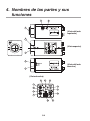
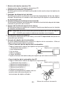
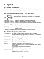
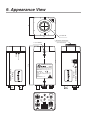
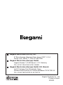
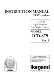
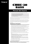
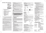
INSTRUCTION MANUAL
B/W CAMERA
MODEL
ICD-48
OUTDOOR USE WARNING
WARNING – TO PREVENT FIRE OR
ELECTRIC SHOCK, DO NOT
EXPOSED THIS APPLIANCE TO
RAIN OR MOISTURE.
Ikegami Tsushinki Co., Ltd.
Thank you very much for your wise choice of the Ikegami B/W Camera. Please carefully
read this Instruction Manual to keep your camera at full capacity.
Contents
1.
2.
3.
4.
5.
6.
7.
8.
9.
10.
Page
Handling precautions ............................................................................... E-1
General .................................................................................................... E-1
Features ................................................................................................... E-1
Names of Parts and their functions .......................................................... E-2
Setting ...................................................................................................... E-5
5-1. User setting ..................................................................................... E-5
5-2. Setting switches and their functions ................................................ E-5
5-3. User setting menus ......................................................................... E-5
Communication Command ...................................................................... E-6
6-1. Communicating conditions .............................................................. E-6
6-2. Command format ............................................................................ E-6
6-3. Communication flow ........................................................................ E-7
6-4. Communication command .............................................................. E-8
6-5. Table of OSD display character codes ............................................ E-9
Specifications ........................................................................................... E-10
Warranty and after-sale service ............................................................... E-11
Appearance View
Setup Menu
The exclamation point within an equilateral triangle is intended to alert the user to the presence of
important operating and maintenance (servicing) instructions in the literature accompanying the
appliance.
NOTE:
This equipment has been tested and found to comply with the limits for a Class A digital device,
pursuant to Part 15 of the FCC Rules. These limits are designed to provide reasonable protection against
harmful interference when the equipment is operated in a commercial environment. This equipment
generates, uses and can radiate radio frequency energy and, if not installed and used in accordance with
the instruction manual, may cause harmful interference to radio communications. Operation of this
equipment in a residential area is likely to cause harmful interference in which case the user will be required
to correct the interference at his own expense.
CAUTION;
ANY CHANGES OR MODIFICATIONS NOT EXPRESSLY APPROVED BY THE PART RESPONSIBLE
FOR COMPLIANCE COULD VOID THE USERS AUTHORITY TO OPERATE THE EQUIPMENT.
Instructions for Disposal of Electric and Electronic Equipment in Private Household
Disposal of used Electric and Electronic Equipment
(Applicable in the European Union and other European countries with separate
collection systems)
This symbol on the product, or in the related documents in the package, indicates that this
product shall not be treated as normal household waste. Instead, it should be taken to a proper
applicable collection point or depot for the recycling of electric and electronic equipment.
By ensuring this product is disposed of correctly, you will help prevent possible negative consequences for the
environment and human health, which could otherwise be caused by inappropriate waste handling of this
product. The recycling of materials will help to conserve natural resources.
For more detailed information about recycling of this product, please contact your local city authority, your
household waste disposal service or the place where you purchased the product.
1. Handling precautions
(1)Do not open the case of camera and never touch inside, where precision parts are
assembled. A trouble or accident may result.
(2)Do not install the unit where it is exposed to water splash, high humidity and heavy
dust. Internal parts may be damaged.
(3)Be very careful not to drop or shock the camera.
(4)Never touch the CCD surface.
2. General
This is a B/W camera of high sensitivity, high resolution and high picture quality using a
1/2 inch CCD having high sensitivity to near-infrared ray.
It has a high resolution of 570 horizontal lines (EIA), minimum illumination of 0.01 lux,
and a smear level of -120 dB, and is equipped with such functions as line lock, automatic
electronic shutter, backlight compensation, two-way automatic iris, etc. It is a high utility
video camera for monitoring the outdoor scene and as a night-vision camera in combination
with near-infrared ray projector.
Moreover, since it is endowed with OSD and RS-485 communicating function, a highgrade monitor system architecture is also possible.
3. Features
(1) Compactness
(2) High sensitivity and high resolution
(3) High sensitivity to near-infrared ray
(4) Reduced smear
(5) Backlight compensation (BLC)
(6) Two-way auto iris function
(7) Line lock
(8) AES (Automatic Electronic Shutter)
(9) Flange focal distance adjustment
(10) RS-485 communicating function
E-1
4. Names of parts and their
functions
7
6
2
(LEFT VIEW)
5
(TOP VIEW)
1
3
(RIGHT VIEW)
4
(BACK VIEW)
8
10
9
14
11
15
12
16
19
13
18
E-2
17
① Lens mount (CS mount)
Accepts many types of CS mount lenses.
② C mount adaptor (Accessory)
Attached to the lens mount to accept many types of C mount lenses.
③ Flange focal distance adjuster
Used to adjust the flange focal distance depending on the type of lens used. Helpful
when the lens’ focus ring fails to put into focus.
④ Flange focal distance lock screw
Used to mechanically lock the flange focal distance after fine adjustment of it.
⑤ Holder screw hole
Used to mount the camera onto the camera holder. Effective for general camera tripods.
Note: Be sure to use less than 5.5mm- long setscrew (1/4” – 20 UNC) for mounting
the camera to tripods or holder.
⑥ Lens selector switch
Used to choose between the video iris and the DC iris depending on the type of auto
iris lens used.
⑦ Auto iris lens connector
Specifically used to connect the auto iris lens. Use the connector plug that is attached
to the camera.
• For the video type auto iris lens
Set the lens selector switch to VIDEO position.
Auto iris lens
— Connector cable leads —
4
2
1. Red (power)
2. Not used
3. White (video)
3
1
4. Black (shielded)
* Dress the tip of the green lead to prevent a short-circuit.
• For the DC type auto iris lens
Set the lens selector switch to DC position.
— Connector cable leads —
2
1. Damping coil (-)
2. Damping coil (+)
3. Driving coil (+)
4. Driving coil (-)
1
* Connect the leads as shown above.
Refer also to the instructions of the lens.
Auto iris lens
4
3
3
1
4
2
Numbers of connector pins
E-3
⑧ - ⑫ Camera setting function switches
Use them by referring to each operation item.
⑬ Video output terminal
Used to give out the video signal. Connect this to the video input terminal of a monitor,
switcher etc. (To be terminated with 75-ohm impedance.)
⑭ External sync signal input terminal
Used to receive the GENLOCK (general lock) signal. For external synchronization,
input VBS or BBS signal.
⑮ External sync signal 75-ohm termination switch
Set to HIGH position when the GENLOCK signal is looped with T-shaped connector.
Usually, set at 75-OHM position.
⑯ Power indicator
Green LED lights up when power is supplied to the camera.
⑰ Terminal switch for RS-485
In RS-485 communication control, turn this switch to ON side for one-to-one control,
and turn it to OFF side for daisy-chain connection. (For use in daisy-chain connection,
turn ON the terminal switch by terminal connection equipment.)
⑱ RS-485 connection terminal block
Used for RS-485 connection.
⑲ AC24V/DC12V power input terminal
Input the power of AC21.6~26.4V or DC10.5~15V.
※ This installation should be made by a qualified service person and should conform
to all local codes.
E-4
5. Setting
5-1. User setting
On this camera, user can make settings of picture quality, synchronization, identification
etc. by himself or herself.
The setup menu is formed in a tree view, and the picture sharpness, synchronization, ID
and others can be set up by on-screen characters. (See the setup tree given in the end
of this manual.)
5-2. Setting switches and their functions
SET UP
L
U
R
D
E
On the back of the camera there are the pushbutton switches and
display as shown at the left.
UP switch (U):
Setting item selection (up)
DOWN switch (D):Setting item selection (down)
RIGHT switch (R): Setting change and setting item selection (right)
LEFT switch (L): Setting change and setting item selection (left)
ENTER (E):
Setting mode call on/off, setting entry
* To enter into the setup mode, keep pressing the E button.
5-3. User setting menus
(1)CAMERA ID
(2)SHUTTER
(3)LIGHT CONT.
(4)GAIN
(5)SYNC
(6)MENU LOCK
Up to 16 characters can be accepted and displayed.
Switching on and off the CAMERA ID function and presetting ID code
characters.
Setting of high-speed electronic shutter
Selection of high-speed shutter, display of the screen at VARIABLE
mode
Selection of AES or auto iris lens
Setting of back-light compensation as sub-menu
Selection of AGC, HYP-AGC and fix
Selection of synchronization system (INT, LL)
(It is impossible to select LL when the power is not synchronous.)
GENLOCK is selected automatically.
(GENLOCK is not displayed without external sync signal.)
It is possible to adjust the phase on sub-menu.
Setting procedure is locked. (Unlocking: U→R→D→L→U →D→E)
● Setting Indications and functions common on the setting menu
(1)EXIT
Ending (Saving) the setting mode and returning to the regular display.
(2)CANCEL
Recalling the previously saved settings.
(3)RESET
Recalling the factory-settings.
(4)RET
Returning to the preceding setting menu.
Select one of these indications and press the E switch.
E-5
6. Communication Command
6-1. Communicating conditions
(1) Baud rate
(2) Data length
(3) Parity
(4) Stop bit
: 9600 bps
: 8 bits
: None
: 1 bit
6-2. Command format
1
2
3
4
5
6
7
8
9
SOH (01h)
Receiving model ID
Receiving sub ID
Transmitting model ID
Optional bit function
Transmitting sub ID
Reservation (80 h)
STX (02h)
*1
*2
*3
*4
*5
Command (Variable length)
n
n+1 ETX (03h)
n+2 BCC (Exclusive-OR of receiving model ID to ETX)
4th to 7th bytes can be omitted.
To the commands omitted of transmitting ID and transmitting sub ID, response is given
from camera in the setting as follow:
Transmitting model ID omitted → No response from camera
Transmitting sub ID omitted
→ Response is given from camera by transmitting sub
ID = 30 h.
*1 Transmitting model ID ICD-48...43h
*2 Transmitting sub ID
ICD-48...Camera No. + 30h (30h ~ FFh)
Set the camera No. by “RS-485 ID” items in the special menu for setup. Camera can not
be operated unless the settings of “Transmitting sub ID” and “RS-485 ID” are identical.
Ex. Camera No. 1 = 31h
Camera No. 15 = 3Fh
E-6
*3 Transmitting model ID Set the transmitting model ID. (20h ~ 7Dh)
Keyboard ID (2Dh) etc.
*4 Optional bit function
Bit
7
6
5
4
3
2
1
0
Settings
Regular 1
Backup
Backup
Backup
Backup
Backup
Backup
Request for ACK/NAK response (0: No, 1: Yes)
*5 Transmitting sub ID Set the transmitting sub ID. (30h ~ FFh)
6-3. Communication flow
Operating machine
ICD-48
Control command
ACK
Inquiry command
ACK
Status command
E-7
6-4. Communication command
Command
1
a
b
2
?
Dat
3
4
5
Function
6
Inquiries by type of camera
Camera ID display ON/OFF
(0:Off, 1:On)
Setting of camera ID display position
c
x1 x2 y1 y2
xx: Horizontal position (07h ~ 3Fh)
yy: Vertical position (02h ~ 35h)
d Pos Str1 Str2 Str3 Str4 Setting of camera ID display characters
Pos: Setting head character position
(0h ~ Fh)
Str: Character code (20h ~ FFh)
g Dat
Setting high-speed shutter speed
0:Off, 1:1/100, 2:1/125, 3:250, 4:1/500,
5:1/1000, 6:1/2000, 7:1/4000, 8:1/10000,
9:Variable, A:1/100000
h Dat
LENS/AES mode (0:LENS, 1:AES)
i Dat
Setting of backlight compensation mode
(0:Off, 1:On, 2:SPOT)
j Dat1 Dat2
Setting of backlight compensation level
(40h~BFh)
l Dat
Gain setting
0:LOW, 1:MID, 2:HIGH,
3:AGC, 4:HYP-AGC
o Dat
Sync. mode setting (0:INT, 1:LL)
p Cor Fin1 Fin2
V-phase setting in LL mode
Cor: LL COARSE
(0:0°, 1:90°, 2:180°, 3:270°)
Fin: LL FINE (00h ~ FFh)
q Pha1 Pha2
Setting gain lock H-phase (00h~FFh)
u Dat1 Dat2
Detail level setting (00h~0Fh)
v Dat1 Dat2
Pedestal level setting (00h~0Fh)
w Sw Lock
Setting of camera body switch input
permission/prohibition
Sw: Switch input (0: prohibit, 1: permit)
Lock: Setup lock (0: Off, 1: On)
x Dat
Storage, cancellation and resetting of setting
(0: store, 1: cancel, 2: reset)
? Cod
Inquiry of setting status
80 Dat1 Dat2 Dat3
Variable shutter speed setting
032h (1/60) ~ 1FFh (1/100000)
82 Dat1 Dat2
DC iris level setting (00h~1Fh)
83 x1 x2 y1 y2
Setting of spot photometric area coordinates
xx: abscissa information
yy: ordinate information
Blank : Space or omittable
E-8
Remarks
*1
Character code
can be designated
up to maximum 16
characters.
*2
*3
*1 Information of the type and software version of camera and is given.
Ex. Inquiry about the type and version of camera for ICD-48 Version 1.00A
a? → ICD-48NV1.00A
*2 Response to the inquiry about the setting status is given in the format identical to that
of each setup expansion command.
Ex. Inquiry about the setting of high-speed shutter speed in OFF setting
? g → g0
*3 Spot photometric area coordinates is designated by information of the following
settings.
However, these settings should be in such combination that the ordinate and abscissa
the right end and the bottom should be maximum within Fh.
x1 : Ordinate at left end in photometric area (0 ~ Fh)
x2 : Width of photometric area (0 ~ Fh)
y1 : Abscissa at the top in photometric area (0 ~ Fh)
y2 : Height of in photometric area (0 ~ Fh)
6-5. Table of OSD display character codes
2
3
4
5
6
7
0
1
0
1
SP
!
0
1
@
A
P
Q
`
a
p
q
2
3
4
“
#
$
2
3
4
B
C
D
R
S
T
b
c
d
r
s
t
5
6
%
&
5
6
R
F
U
V
e
f
u
v
7
8
‘
(
7
8
G
H
W
X
g
h
w
x
9
A
)
∗
9
:
I
J
Y
Z
i
j
y
z
B
C
→
+
,
↑
←
K
L
[
¥
k
l
D
E
←
↑
–
.
↓
→
M
N
]
^
m
n
F
↓
/
O
_
o
E-9
7. Specifications
(1)
(2)
(3)
(4)
(5)
(6)
Imaging device:
Effective pixels:
Scanning system:
Scanning system:
Synchronization system:
GENLOCK input:
1/2 inch, IT-CCD
768(H) x 494(V), about 380,000 pixels
2:1 interlace, as per EIA system
525 lines at 59.94 Hz
INT, LINE LOCK, GENLOCK
VBS or VS; 1.0 Vp-p/75 ohms (High impedance
selectable)
BBS; 0.45 Vp-p/75 ohms (High impedance selectable)
(7) Video output:
VS; 1.0 Vp-p/75 ohms
(8) Horizontal resolution:
570 TV lines
(9) S/N ratio:
50 dB/rms or more
(AGC OFF, DETAIL OFF, weighting ON)
(10) Minimum illumination:
0.01 lux/F1.4 (AGC ON)
(Color temp.: 2856K, Light source: Halogen lamp)
(11) Backlight compensation function: ON/OFF switchable
(12) AES function:
ON/OFF switchable
(AES range: About 1 : 1600)
(13) High-speed electronic shutter: Make selection among 1/60~1/100,000 sec. , 9-STEP and
VARIABLE.
In the case of "VARIABLE", it can be set within the range
of 1/60~1/100,000 sec.
(14) AGC (Automatic gain control): ON (AGC, HYPER AGC)/OFF (LOW, MID, HIGH)
switchable
(15) Auto iris function:
Compatible with video iris and DC iris (selectable)
(With DC iris level adjuster)
(16) Camera ID function:
Provided (One line, 16 characters)
(17) Local setting functions:
Selectable and adjustable with on-screen display using 5
control buttons; Camera ID, AES/electronic shutter, BLC
ON/OFF/SPOT selection and level adjustment, DC iris
level, INT/LL, external sync frequency phase adjustment,
DETAIL level, AGC ON/OFF, PED. level, menu lock
selectable.
(18) RS-485 communicating function: Provided
Control item:
Settable items include local setup function and RS-485
function ID.
(19) Lens mount:
CS/C mount (with C mount adaptor)
(20) Flange focal distance adjuster: Provided
(21) Power supply:
AC 24V ±10%, 60 Hz/ DC 12V (10.5-15V)
(However, the power supply should withstand 48-hour
continuous operation at +20%)
(22) Power consumption:
AC/24V/DC12V: Approx. 4.3W
(23) Ambient temp./humidity
-10°C to +50°C/Within 30~90%RH
for operation:
(No dew condensation)
E-10
(24) Camera mount:
(25) External dimensions:
(W x H x D)
(26) Weight:
(27) I/O connectors:
(28) Accessories:
1/4"-20UNC
(Attachable on top and bottom.)
62(W) x 55(H) x 118(D) mm (No projections included)
Approx. 430 g
• VIDEO OUT:
BNC
• GENLOCK IN:
BNC
• LENS:
4-pin
(Applicable plug: E4-191J-150 or equivalent)
• RS-485 communicating: 5 pin push-in terminal
• AC 24V/DC 12V input: 2 pin push-in terminal
• Instruction manual
1
• C mount adaptor
1
* The specifications and appearance may be subject to change without prior notice.
8. Warranty and after-sale service
A warranty accompanies this product. Read and fill out the warranty card that you have
received at your dealer. Keep this card in a safe place.
• Please consult Ikegami Electronics (U.S.A.), Inc. or your dealer for full warranty
information. Your dealer will repair or replace free of charge within the warranty period
according to the warranty coverage.
• For repairs after the expiration of the warranty period, consult your dealer or sales
representative. It will first be judged whether the trouble is repairable or not. Charged
servicing will then be made upon the request of user.
• Before you ask for servicing, take trouble of reading the Instruction Manual. If the
unit still fails, take note of the model number, date of purchase, problem etc. in detail,
and inform your dealer or sales representative.
• If you have questions about the after-sale service, contact your dealer or sales
representative.
* We suggest you ask for preventive inspection earlier.
E-11
Muchísimas gracias por haber elegido la cámara en N/B de Ikegami. Lea cuidadosamente este manual
de instrucciones para mantener su cámara en las mejores condiciones de funcionamiento.
Indice
1.
2.
3.
4.
5.
6.
7.
8.
9.
10.
Page
Precauciones de manejo ......................................................................... S-1
Nociones generales ................................................................................. S-1
Características ......................................................................................... S-1
Nombres de las partes y sus funciones ................................................... S-2
Ajuste ....................................................................................................... S-5
5-1. Ajuste del usuario ............................................................................ S-5
5-2. Conmutadores de ajuste y sus funciones ....................................... S-5
5-3. Menús de ajuste del usuario ........................................................... S-5
Comando de comunicación ..................................................................... S-6
6-1. Condiciones de comunicación ........................................................ S-6
6-2. Formato de comando ...................................................................... S-6
6-3. Flujo de comunicación .................................................................... S-7
6-4. Comando de comunicación ............................................................. S-8
6-5. Tabla de códigos de caracteres de visualización OSD .................... S-9
Especificaciones ...................................................................................... S-10
Garantía y servicio postventa .................................................................. S-12
Appearance View
Setup Menu
El signo de exclamaci n dentro de un tri ngulo equil tero tiene la finalidad de avisar al usuario de
la presencia de instrucciones de funcionamiento y mantenimiento (reparaciones) importantes en los
manuales que acompa an al aparato.
NOTA:
Este equipo ha sido probado y ha demostrado cumplir con los l mites establecidos para los dispositivos digitales de
la clase A, de conformidad con el Apartado 15 de las normas de la FCC. Estos l mites han sido establecidos para
proporcionar una protecci n razonable contra la interferencia perjudicial cuando el equipo se utiliza en un ambiente
comercial. Este equipo genera, utiliza y puede radiar energ a radioel ctrica, y, si no se instala y utiliza seg n las
indicaciones del manual de instrucciones, puede causar interferencias perjudiciales en las comunicaciones por
radio. El funcionamiento de este equipo en una zona residencial causar probablemente interferencias
perjudiciales, en cuyo caso, el usuario tendr que eliminarlas corriendo el mismo con los gastos pertinentes.
AVISO:
CUALQUIER CAMBIO O MODIFICACI N NO APROBADA EXPRESAMENTE POR LA PARTE RESPONSABLE DEL BUEN
FUNCIONAMIENTO DEL APARATO PODRŒA ANULAR LA AUTORIZACI N DEL USUARIO PARA UTILIZAR EL EQUIPO.
Instrucciones para eliminar equipos eléctricos y electrónicos de una casa privada
Eliminación de equipos eléctricos y electrónicos usados
(Normas aplicables en la Unión Europea y en otros países europeos con diferentes
sistemas de recogida)
Este símbolo en el producto, o en los documentos relacionados, indica que este producto no
deberá ser tratado como un residuo doméstico normal. En cambio, deberá ser llevado a un
punto o lugar donde los equipos eléctricos y electrónicos sean recogidos para ser reciclados.
Asegurándose de que este producto sea eliminado correctamente, usted ayudará a impedir las posibles
consecuencias negativas sobre el medio ambiente y la salud humana que podrían ser causadas por el
manejo inapropiado de este producto como residuo doméstico. El reciclado de los materiales ayudará a
conservar los recursos naturales.
Para conocer una información más detallada acerca del reciclado de este producto, póngase en contacto con
las autoridades de su localidad, con su servicio de recogida de residuos domésticos o con el comercio donde
adquirió el producto.
1. Precauciones de manejo
(1)No abra la caja de la cámara ni toque nunca el interior de la misma, donde se
encuentran instaladas piezas de alta precisión. De lo contrario podría ocurrir un
problema o un accidente.
(2)No instale la unidad donde quede expuesta a las salpicaduras del agua, a un humedad
alta y al polvo pesado. Las piezas internas pueden dañarse.
(3)Tenga cuidado de no dejar caer ni golpear la cámara.
(4)No toque nunca la superficie del CCD.
2. Nociones generales
Ésta es una cámara en B/N de alta sensibilidad, alta resolución y alta calidad de imagen
que emplea un CCD de 1/2 pulgada altamente sensible al rayo infrarrojo próximo.
Tiene una resolución alta de 570 líneas horizontales (EIA), una iluminación mínima de
0,01 luxes y un nivel de borrosidad de –120 dB, y está equipada con funciones tales
como bloqueo de línea, obturador electrónico automático, compensación de luz de fondo,
iris automático de dos vías, etc. Es una videocámara de mucha utilidad para monitorear
escenas exteriores y sirve también como una cámara de visión nocturna cuando se
combina con un proyector de rayo infrarrojo próximo.
Además, como dispone de OSD y función de comunicación RS-485, también es posible
disponer de una arquitectura de sistema de monitoreo de alta calidad.
3. Características
(1) Compactibilidad
(2) Alta sensibilidad y alta resolución
(3) Alta sensibilidad al rayo infrarrojo próximo
(4) Borrosidad reducida
(5) Compensación de luz de fondo (BLC)
(6) Función de iris automático de dos vías
(7) Bloqueo de línea
(8) AES (Obturador electrónico automático)
(9) Ajuste de distancia focal de brida
(10) Función de comunicación RS-485
S-1
4. Nombres de las partes y sus
funciones
7
6
2
(Vista del lado
izquierdo)
5
(Vista superior)
1
3
(Vista del lado
derecho)
4
(Vista derecha)
8
10
9
14
11
15
12
16
19
13
18
S-2
17
① Montura del objetivo (montura CS)
Acepta muchos tipos de objetivos de montura CS.
② Adaptador de montura C (Accesorio)
Se coloca en la montura del objetivo para poder instalar muchos tipos de objetivos de
montura C.
③ Ajustador de distancia focal de brida
Se utiliza para ajustar la distancia focal de brida dependiendo del tipo de objetivo
utilizado. Resulta muy útil cuando el anillo de enfoque del objetivo no puede realizar
un enfoque adecuado.
④ Tornillo de bloqueo de distancia focal de brida
Se utiliza para bloquear mecánicamente la distancia focal de brida después de haber
realizado el ajuste fino de la misma.
⑤ Agujero del tornillo del soporte de la cámara
Se utiliza para montar la cámara en su soporte. Resulta muy efectivo para los trípodes
de cámaras convencionales.
Nota: Asegúrese de utilizar tornillos de fijación de menos de 5,5 mm de longitud
(1/4" - 20 UNC) para montar la cámara en trípodes o en el soporte.
⑥ Conmutador selector de objetivo
Se utiliza para elegir entre el iris de vídeo y el iris de DC dependiendo del tipo de iris
automático que se utilice.
⑦ Conector de objetivo de iris automático
Se utiliza específicamente para conectar el objetivo de iris automático. Utilice el
conector que está colocada en la cámara.
• Para el vídeo del tipo de objetivo de iris automático
Ponga el conmutador selector del objetivo en la posición VIDEO.
— Conductores de conexión —
Objetivo de iris automático
4
2
1. Rojo (alimentación)
2. No se utiliza
3. Blanco (imagen)
3
1
4. Negro (blindado)
* Prepare el extremo del cable verde para impedir que se formen cortocircuitos.
• Para el objetivo de iris automático tipo DC
Ponga el conmutador selector de objetivo en la posición DC.
Objetivo de iris automático
— Conductores de conexión —
4
2
1. Bobina de amortiguamiento (–)
2. Bobina de amortiguamiento (+)
3. Bobina de excitación (+)
3
1
4. Bobina de excitación (–)
* Conecte correctamente los cables como se
3
muestra más arriba consultando las
instrucciones del objetivo utilizado.
1
4
2
Número de contactos de conexión
S-3
⑧ - ⑫ Conmutadores de funciones de ajuste de la cámara
Utilícelos consultando cada elemento de la operación.
⑬ Terminal de salida de vídeo
Se utiliza para dar salida a la señal de vídeo. Conecte este terminal al terminal de
entrada de vídeo de un monitor, conmutador, etc. (Será terminado con una impedancia
de 75 ohmios.)
⑭ Terminal de entrada de señal de sincronización externa
Se utiliza para recibir la señal GENLOCK (bloqueo general). Para la sincronización
externa, introduzca una señal VBS o BBS.
⑮ Conmutador de terminación de 75 ohmios para la señal de sincronización externa
Póngalo en la posición HIGH cuando la señal GENLOCK se conecte en bucle con el
conector en forma de T. Generalmente, póngalo en la posición 75-OHM.
⑯ Indicador de alimentación
El LED verde se enciende cuando se suministra alimentación a la cámara.
⑰ Conmutador de terminal para RS-485
En el control de comunicación RS-485, ponga este conmutador en el lado ON para
hacer el control uno a uno, y póngalo en el lado OFF para hacer la conexión en
cadena tipo margarita. (Para el uso de conexión en cadena tipo margarita, active el
conmutador de terminal mediante el equipo de conexión de terminal.)
⑱ Bloque terminal de conexión RS-485
Se usa para la conexión RS-485.
⑲ Terminal de entrada de alimentación CA 24 V/CC 12 V
Entrada de alimentación de CA 21,6~26,4 V o CC 10,5~15 V.
※ Esta instalación deberá ser realizada por un técnico cualificado y deberán cumplir
con todos los reglamentos locales.
S-4
5. Ajuste
5-1. Ajuste del usuario
El menú de configuración tiene forma de árbol, y la nitidez de la imagen, la sincronización,
la identificación y demás pueden configurarse mediante caracteres en pantalla. (Consulte
el árbol de configuración al final de este manual.)
5-2. Conmutadores de ajuste y sus funciones
En la parte posterior de la cámara, como se muestra a la izquierda,
se encuentran los conmutadores pulsadores y el visualizador.
SET UP
U
L
R
D
E
Conmutador UP (U):
Selección (ascendente) de elementos de ajuste
Conmutador DOWN (D): Selección (descendente) de elementos de ajuste
Conmutador RIGHT (R): Cambio de ajuste y selección (hacia la derecha) de elementos
de ajuste
Conmutador LEFT (L): Cambio de ajuste y selección (hacia la izquierda) de elementos
de ajuste
ENTER (E):
Activación/desactivación de la llamada al modo de ajuste,
entrada de ajuste
* Para entrar en el modo de configuración, mantenga pulsado el botón E.
5-3. Menús de ajuste del usuario
(1)CAMERA ID
Se puede aceptar y visualizar un máximo de 16 caracteres.
Activación/desactivación de la función CAMERA ID y preajuste de
los caracteres del código ID.
(2)SHUTTER
Ajuste del obturador electrónico de alta velocidad
Selección del obturador de alta velocidad, visualización de la pantalla
en el modo VARIABLE.
(3)LIGHT CONT. Selección de AES o del objetivo de iris automático
Ajuste de la compensación de luz de fondo como menú secundario
(4)GAIN
Selección de AGC, HYP-AGC y fijación
(5)SYNC
Selección del sistema de sincronización (INT, LL)
(No es posible seleccionar LL cuando la alimentación no está
sincronizada.)
GENLOCK se selecciona automáticamente.
(GENKLOCK no se visualiza sin señal de sincronización externa.)
En el menú secundario se puede ajustar la fase.
(6)MENU LOCK El procedimiento de ajuste se bloquea.
(Desbloqueo: U→R→D→L→U→D→E)
S-5
● Ajuste de indicaciones y funciones comunes en el menú de ajuste
(1)EXIT
Se finaliza (guarda) el modo de ajuste y se vuelve a la visualización
convencional.
(2)CANCEL
Llamada a los ajustes guardados previamente.
(3)RESET
Recuperación de los ajustes de fábrica.
(4)RET
Retorno al menú de ajuste anterior.
Seleccione una de estas indicaciones y pulse el conmutador E.
6. Comando de comunicación
6-1. Condiciones de comunicación
(1) Velocidad de transmisión en baudios
(2) Longitud de datos
(3) Paridad
(4) Bit de parada
:9600 bps
:8 bits
:Ninguna
:1 bit
6-2. Formato de comando
1
2
3
4
5
6
7
8
9
SOH (01h)
Identificación del modelo de recepción
Identificación secundaria de recepción
Identificación del modelo de transmisión
Función de bit opcional
Identificación secundaria de transmisión
Reserva (80 h)
STX (02h)
*1
*2
*3
*4
*5
Comando (Longitud variable)
n
n+1 ETX (03h)
n+2 BCC (Circuito OR exclusivo de identificación del
modelo de recepción a ETX)
Se pueden omitir los bytes 4to. a 7mo.
A los comandos omitidos de la identificación de transmisión e identificación secundaria
de transmisión, la respuesta se da desde la cámara con el ajuste siguiente:
Identificación de modelo de transmisión omitida → No hay respuesta desde la cámara
Identificación secundaria de transmisión omitida → Hay respuesta desde la cámara
mediante la identificación secundaria de transmisión = 30 h.
S-6
*1 Identificación del modelo de transmisión
*2 Identificación secundaria de transmisión
ICD-48...43h
ICD-48...N.° de cámara + 30h (30h ~ FFh)
Ponga el número de la cámara mediante los elementos “RS-485 ID” en el menú especial
para instalación. La cámara no se podrá utilizar a menos que los ajustes de “Identificación
secundaria de transmisión” y “RS-485 ID” sean idénticos.
Ejemplo: Cámara N.° 1 = 31h
Cámara N.° 15 = 3Fh
*3 Identificación del modelo de transmisión: Ponga la identificación del modelo de
transmisión. (20h ~ 7Dh)
Identificación de teclado (2Dh), etc.
*4 Función de bit opcional
Bit
7
6
5
4
3
2
1
0
Ajustes
Regular 1
Apoyo
Apoyo
Apoyo
Apoyo
Apoyo
Apoyo
Solicitud de respuesta ACK/NAK (0: No, 1: Sí)
*5 Identificación secundaria de transmisión
transmisión. (30h ~ FFh)
Ponga la identificación secundaria de
6-3. Flujo de comunicación
Máquina en funcionamiento
ICD-48
Comando de control
ACK
Comando de pregunta
ACK
Comando de estado
S-7
6-4. Comando de comunicación
1
a
b
2
?
Dat
Comando
3
4
5
Función
6
Preguntas por tipo de cámara
Encendido/Apagado de visualización de
identificación de cámara (0:OFF, 1:ON)
c
x1 x2 y1 y2
Ajuste de la posición de visualización de
identificación de cámara
xx: Posición horizontal (07h ~ 3Fh)
yy: Posición vertical (02h ~ 35h)
d Pos Str1 Str2 Str3 Str4 Ajuste de los caracteres de visualización de
identificación de cámara
Pos: Ajuste de la posición de caracteres
de encabezamiento (0h ~ Fh)
Str: Código de caracteres (20h ~ FFh)
g Dat
Ajuste de la velocidad del obturador de alta
velocidad
0:Off, 1:1/100, 2:1/125, 3:250, 4:1/500,
5:1/1000, 6:1/2000, 7:1/4000, 8:1/10000,
9:Variable, A:1/100000
h Dat
Modo LENS/AES (0:LENS, 1:AES)
i
Dat
Ajuste del modo de compensación de luz de
fondo (0:OFF, 1:ON, 2:SPOT)
Ajuste del nivel de compensación de luz de fondo
j Dat1 Dat2
(40h~BFh)
l
Dat
Ajuste de ganancia
0:LOW, 1:MID, 2:HIGH,
3:AGC, 4:HYP-AGC
o Dat
Ajuste del modo de sincronización (0:INT, 1:LL)
p Cor Fin1 Fin2
Ajuste de fase V en el modo LL
Cor: LL COARSE (0:0°, 1:90°, 2:180°,3:270°)
Fin: LL FINE (00h ~ FFh)
Ajuste de fase H del bloqueo de ganancia
q Pha1 Pha2
(00h~FFh)
u Dat1 Dat2
Ajuste del nivel de detalle (00h~0Fh)
v Dat1 Dat2
Ajuste del nivel de pedestal (00h~0Fh)
Ajuste de permiso/prohibición de entrada del
w Sw Lock
conmutador del cuerpo de la cámara
Sw: Entrada de conmutador
(0: prohibida, 1: permitida)
Lock: Bloqueo de instalación
(0: Off, 1: On)
Almacenamiento, cancelación y reposición de
x Dat
ajuste (0: almacenar, 1: cancelar, 2: reponer)
? Cod
Pregunta del estado del ajuste
Ajuste de velocidad de obturador variable
80 Dat1 Dat2 Dat3
032h (1/60) ~ 1FFh (1/100000)
82 Dat1 Dat2
Ajuste de nivel de iris DC (00h~1Fh)
83 x1 x2 y1 y2
Ajuste de coordenadas de área
fotométrica de punto
xx: información de abscisa
yy: información de ordenada
En blanco : Espacio o se puede omitir
S-8
Observaciones
*1
El código de
caracteres se
puede designar
con un máximo
de 16 caracteres.
*2
*3
*1 Se da información del tipo y versión de software de la cámara.
Ejemplo: Pregunta acerca del tipo y versión de cámara para ICD-48 Version 1.00A
a? → ICD-48NV1.00A
*2 Se da respuesta a la pregunta acerca del estado del ajuste en formato idéntico al de
cada comando de expansión de instalación.
Ejemplo: Pregunta acerca del ajuste de velocidad del obturador de alta velocidad
en OFF
? g → g0
*3 Las coordenadas del área fotométrica de punto se designan mediante la información
de los ajustes siguientes.
Sin embargo, estos ajustes deberán estar combinados de tal forma que la ordenada y la
abscisa en el extremo derecho y en la parte inferior sean las máximas dentro de Fh.
x1 : Ordenada en el extremo izquierdo del área fotométrica (0 ~ Fh)
x2 : Anchura del área fotométrica (0 ~ Fh)
y1 : Abscisa en la parte superior del área fotométrica (0 ~ Fh)
y2 : Altura en el área fotométrica (0 ~ Fh)
6-5. Tabla de códigos de caracteres de visualización OSD
0
0
1
2
SP
3
0
4
@
5
P
6
`
7
p
1
2
!
“
1
2
A
B
Q
R
a
b
q
r
3
4
#
$
3
4
C
D
S
T
c
d
s
t
5
6
%
&
5
6
R
F
U
V
e
f
u
v
7
8
‘
(
7
8
G
H
W
X
g
h
w
x
9
A
)
∗
9
:
I
J
Y
Z
i
j
y
z
B
C
→
+
,
↑
←
K
L
[
¥
k
l
D
E
←
↑
–
.
↓
→
M
N
]
^
m
n
F
↓
/
O
_
o
S-9
7. Especificaciones
(1)
(2)
(3)
(4)
(5)
(6)
Dispositivo de formación de imagen:
Píxeles efectivos:
Sistema de exploración:
Sistema de exploración
Sistema de sincronización:
Entrada GENLOCK:
(7) Salida de vídeo:
(8) Resolución horizontal:
(9) Relación señal/ruido:
(10) Iluminación mínima:
(11) Función de compensación de
luz de fondo:
(12) Función AES:
1/2 pulgada, IT-CCD
768 (H) x 494 (V), unos 380.000 píxeles
Entrelazado 2:1, como el sistema EIA
525 líneas a 59,94 Hz
INT, Bloqueo de línea, GENLOCK
VBS o VS; 1,0 Vp-p/75 ohmios (alta impedancia
seleccionable)
BBS; 0,45 Vp-p/75 ohmios (alta impedancia
seleccionable)
VS; 1,0 Vp-p/75 ohmios
570 líneas
50 dB/rms o más
(AGC OFF, DETAIL OFF, ponderación activada)
0,01 luxes/F1.4 (Temperatura del color: 2856K,
fuente de luz: Lámpara halógena)
ON/OFF, conmutable
ON/OFF, conmutable
(Gama AES: 1 : 1.600 aproximadamente)
(13) Obturador electrónico de alta velocidad: Seleccione entre 1/60~1/100.000 de segundo, 9STEP y VARIABLE.
En el caso de “VARIABLE”, se puede ajustar un
valor cualquiera dentro del margen de 1/60~
1/100.000 segundos.
(14) AGC (Control de ganancia automática): ON (AGC,HYPER AGC)/OFF (LOW, MID, HIGH),
conmutable
(15) Función de iris automático:
Compatible con iris de vídeo e iris DC
(seleccionable)
(Con regulador de nivel de iris DC)
(16) Función de identificación de cámara: Provista (Una línea, 16 caracteres)
(17) Funciones de ajuste local:
Seleccionables y ajustables con la visualización en
pantalla utilizando 5 botones de control;
identificación de cámara, AES/obturador electrónico,
selección BLC ON/OFF/SPOT y ajuste de nivel,
nivel de iris DC, INT/LL, ajuste de fase de
frecuencia de sincronización externa, nivel DETAIL,
AGC ON/OFF, nivel PED., bloqueo de menú
seleccionable.
(18) Función de comunicación RS-485:
Provista
Elemento de control:
Entre los elementos que se pueden configurar se
incluye la función de configuración local y la
identificación de la función RS-485.
(19) Montura de objetivo:
Montura CS/C (con adaptador para montura C)
(20) Regulador de distancia focal de brida: Suministrado
S-10
(21) Alimentación:
(22) Consumo:
(23) Temperatura/humedad ambiental
de funcionamiento:
(24) Montura de cámara:
(25) Dimensiones externas:
(An x Al x Prof)
(26) Peso:
(27) Conectores de entrada/salida:
(29) Accesorios
24 V CA ±10%, 60 Hz / 12 V CC (10,5-15 V)
(Sin embargo, la alimentación deberá ser capaz de
resistir un funcionamiento continuo de 48 horas a +20%)
24 V CA/12 V CC: Aproximadamente 4,3 W
–10°C a +50°C/Dentro del 30~90% de humedad
relativa (Sin condensación de humedad)
1/4"–20UNC
(Se puede colocar en la parte superior e inferior.)
62 (An) x 55 (Al) x 118 (Prof) mm
(Sin incluir proyecciones)
Aproximadamente 430 g
• VIDEO OUT: BNC
• GENLOCK IN: BNC
• LENS:
4 contactos
(Clavija aplicable: E4-191J-150 o equivalente)
• Comunicación RS-485:
Terminal de encaje
de 5 contactos
• Entrada de 24 V CA/12 V CC: Terminal de encaje
de 2 contactos
• Manual de instrucciones
1
• Adaptador de montura C
1
* Las especificaciones y la apariencia pueden estar sujetas a cambios sin previo aviso.
S-11
8. Garantía y servicio postventa
Este producto va acompañado de una garantía. Lea y rellene la tarjeta de garantía que le ha entregado
su concesionario. Guarde esta tarjeta en un lugar seguro.
• Consulte a Ikegami Electronics (U.S.A.) Inc. o a su concesionario para obtener
información completa acerca de la garantía. Su concesionario hará gratis las
reparaciones o reemplazos que necesite su aparato siempre que la garantía esté
vigente y se cumplan las condiciones de la misma.
• Para hacer reparaciones una vez caducada la garantía, consulte a su concesionario
o representante de ventas. Primero se tendrá en consideración si el problema puede
ser reparado o no. Y luego se le indicará al usuario el coste del servicio si éste así lo
solicita.
• Antes de solicitar el servicio de reparaciones, lea con atención el manual de
instrucciones. Si no puede solucionar el problema, anote el número del modelo y la
fecha de adquisición, describa con todo detalle el problema, etc. e informe a su
concesionario o representante de ventas.
• Si tiene alguna pregunta relacionada con el servicio postventa, consulte a su
concesionario o representante de ventas.
* Le sugerimos que solicite siempre una inspección preventiva.
S-12
55
9. Appearance View
1"-32UN-2B
62
C MOUNT ADAPTOR
(ACCESSORY)
2-1/4"-20UNC
I KEGAMI TSUSHINKI CO., LTD.
MADE IN JAPAN
GENLOCK IN
SET UP
L
U
R
D
E
HIGH
75‰ POWER
VIDEO OUT
DC12V3.9W
AC24V60Hz4.3W
TERM
OFF
ON
RS-485
– +
–+–+
GND
CLASS 2
LENS
DC
Digital
Digital
V I D E O CAMERA
B/W CAMERA
TYPE
MODEL ICD – 48
AC 24 V 60 Hz 4.3 W/DC 12 V 3.9 W REV.
SER. NO.
DATE
V I D E O CAMERA
118
5C46
VIDEO
Max40mA
FOCUS ADJ
LOCK
COMMERCIAL CCTV PRODUCT
¤
THIS DEVICE COMPLIES WITH PART 15 OF THE FCC RULES. OPERATION IS
SUBJECT TO THE FOLLOWING TWO CONDITIONS: (1) THIS DEVICE MAY NOT
CAUSE HARMFUL INTERFERENCE. AND (2) THIS DEVICE MUST ACCEPT ANY
INTERFERENCE RECEIVED. INCLUDING INTERFERENCE THAT MAY CAUSE
UNDESIRED OPERATION.
SETUP MENU
PUSH E
FOR A WHILE
D
R
GAIN
LOW
MID
HIGH
AGC
HYP-AGC
+E
AES
+E
+E
R
LENS
D
LIGHT CONT.
L
U
OFF
1/100
1/125
1/250
1/500
1/1000
1/2000
1/4000
1/10000
1/100000
VARIABLE
ON
OFF
TOP
SHUTTER
CAMERA ID
L
U
*ALPHANUMERIC
*POSITION
RET
L
D
U
R
+E
D
R
+E
SPOT
+E
+E
*ADJUST
EXIT
SPOT SET
IRIS LEVEL
RET
+E
+E
*ADJUST
R
BLC LEVEL
+E
*ADJUST
EXIT
*ADJUST
*ADJUST
EXIT
D
IRIS LEVEL
+E
+E
L
U
RET
BLC LEVEL
R
IRIS LEVEL
D
OFF
RET
L
U
ON
+D
*ADJUST
1/60 - 1/100000
EXIT
L
U
2ND
D
U
*ADJUST
L
R
3RD
10. Setup Menu
OFF
CANCEL
RESET
MENU LOCK
EXIT
TOP
PUSH
L AND R
AT ONCE
SPECIAL MENU
EXT VS
LL
INT
AUTO-CHANGE
SYNC
+E
+E
+E
+E
*BEFORE SETTING
*DEFAULT
ON
+URDLUDE
EXIT
RET
2ND
ENGLISH
FRANCAIS
LANGUAGE
+E
*ADJUST
*ADJUST
SETTING (001-207)
+E
+E
DETAIL
PEDESTAL
RS-485 ID
+E
*ADJUST
EXIT
H.PHASE
RET
+E
EXIT
RET
+E
*ADJUST
*ADJUST
COARSE
FINE
EXT VS
RET
+E
EXIT
+E
3RD
Ikegami Electronics (U.S.A.), Inc.
37 Brook Avenue, Maywood, New Jersey 07607, U.S.A.
Phone: (201) 368-9171, FAX 201-569-1626
Ikegami Electronics (Europe) GmbH
Ikegami Strasse 1, 41460 Neuss 1, F.R. Germany
TEL. 02131-123-0/FAX 02131-102820
Ikegami Electronics (Europe) GmbH U.K. Branch
Unit E1 Cologne Court Brooklands Close,
Windmill Road Sunbury-on-Thames Middlesex TW16 7EB, UK
TEL. 01932-769700/FAX 01-92-769710
Ikegami Tsushinki Co., Ltd.
Printed in Japan.
K35209