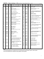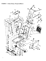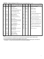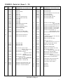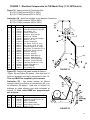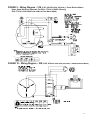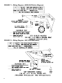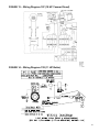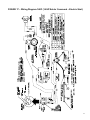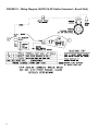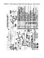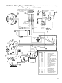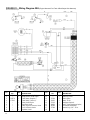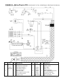
1
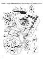
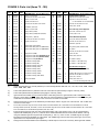
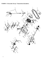
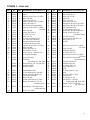
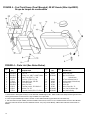
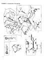
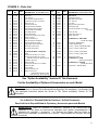
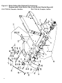
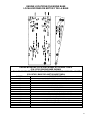
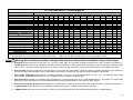
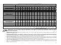
PARTS LIST
LISTA DE PIEZAS
PORT-A-CUT IV
MODELS:
PAC IV–51E
PAC IV–53E
PAC IV–75E
PAC IV–9W
PAC IV–10Y
PAC IV–11R
PAC IV-13.5R PAC IV–14KC PAC IV–14KCR
PAC IV–16KM PAC IV–16BV PAC IV–18BV
PAC IV–20H (Engine Mounted Fuel Tank)
PAC IV–20H (Cowl Mounted Fuel Tank)
PAC IV–8KM
PAC IV–13H
PAC IV–14KM
PAC IV–18H
This Document Supersedes ONLY The “Parts List” Section of
Document P/N 0A7669 “PAV IV Operating Instruction & Parts List”.
Continue Usage Of P/N 0A7669 “Operating Instructions & Parts List”
As “Operating Instructions” For 8KM, 9W, 10Y, 11R, 16BV, 18BV
Models.
Este documento reemplaza SOLAMENTE a la “Lista de Piezas” del
documento P/N 0A7669 “Instrucciones de Operación y Lista de
Piezas del PAV IV”.
Continúa el uso de P/N 0A7669 “Instrucciones de Operación y Lista
de Piezas” como “Instrucciones de Operación” para los modelos
8KM, 9W, 10Y, 11R, 16BV, 18BV.
0A7769
Copyright © December 11, 2003 Electrolux Construction Products.
Printed in USA
17400 West 119th Street
Olathe, Kansas 66061
Customer Service............ 800-288-5040
Corp. Office ..................... 913-928-1000
Cust. Service FAX........... 800-825-0028
Corp. Office FAX ............ 913-438-7951
Customer Service, Int’l .... 913-928-1258
Int’l. FAX ......................... 913-438-7938
Internet......... http://www.targetblue.com
Target Latin America, Mexico,
Caribbean, Central & South
America
17400 West 119th Street
Olathe, Kansas 66061
Phone.............................. 913-928-1255
Fax.................................. 913-438-7938
PARTS LIST INDEX
For quick supply of spare parts and to avoid any lost time, it is essential to quote the data on the
manufacturer’s plate fixed to the machine and the part description to be replaced with every order.
Model Designation Key
Model
PACIV-51E
PACIV-53E
PACIV-75E
PACIV-8KM *
PACIV-9W *
PACIV-10Y **
PACIV-11R *
PACIV-13H
PACIV-13.5R
POWER SOURCE
5 HP Baldor Electric (1 Phase)
5 HP Baldor Electric (3 Phase)
7-1/2 HP Baldor Electric (3 Phase)
8 HP Kohler Magnum
9 HP Wisconsin
10 HP Yanmar Diesel
11 HP Robin
13 HP Honda
13.5 HP Robin
Model
PACIV-14KC
PACIV-14KCR
PACIV-14KM *
PACIV-16KM
PACIV-16BV *
PACIV-18BV *
PACIV-18H *
PACIV-20H
POWER SOURCE
14 HP Kohler Command (Electric)
14 HP Kohler Command (Recoil)
14 HP Kohler Magnum
16 HP Kohler Magnum
16 HP Briggs & Stratton
18 HP Briggs & Stratton
18 HP Honda
20 HP Honda
* Model Out Of Production – Shown For Service Parts Only
** 10Y Model Available Only Upon Special Request
DESCRIPTION
PAGE
Warnings .........................................................................................................................................4 - 5
Figures & Parts Lists & Wiring Diagrams:
1. Frame Group.....................................................................................................................6 - 9
2. Engine & Blade Shaft Group .............................................................................................10 - 15
3. Drivematic Group ..............................................................................................................16 – 18
4. Fuel Tank Group – 20H.....................................................................................................19
5. Accessories.......................................................................................................................20 - 21
6. Wide Cutting Kits (3/4″ & 1″ Wide) (Special Option).........................................................22 - 24
7. Electrical Components (7-1/2 Electric Model Only)...........................................................25
8. Wiring Diagram: 75E.........................................................................................................26
9. Wiring Diagram: 51E.........................................................................................................27
10. Wiring Diagram: 53E.........................................................................................................27
11. Wiring Diagram: 8KM........................................................................................................28
12. Wiring Diagram: 9W..........................................................................................................28
13. Wiring Diagram: 10Y.........................................................................................................29
14. Wiring Diagram: 11R.........................................................................................................29
15. Wiring Diagram: 13H.........................................................................................................30
16. Wiring Diagram: 14KM......................................................................................................30
17. Wiring Diagram: 14KC ......................................................................................................31
18. Wiring Diagram: 14KCR....................................................................................................32
19. Wiring Diagram: 16KM......................................................................................................33
20. Wiring Diagram: 16BV / 18BV...........................................................................................34
21. Wiring Diagram: 18H & 20H..............................................................................................35
22. Wiring Diagram: 20H (Red Stripe Wire Harness) .............................................................36
23. Wiring Diagram: 20H (Blue Stripe Wire Harness).............................................................37
Decal Descriptions and Locations ...................................................................................................38 - 40
Engine Mounting Locations & Base Attaching Points......................................................................41
Option Availability Chart - Per Model...............................................................................................43 - 45
Repair and Spare Parts ..................................................................................................................45
Additional Warnings ........................................................................................................................Back Cover
2
INDICE DE LA LISTA DE PIEZAS
Para una rápida provisión de las piezas de repuesto y para evitar cualquier pérdida de tiempo, con cada
orden de compra es esencial mencionar los datos de la placa del fabricante fijada a la máquina y la
descripción de la pieza a ser reemplazada.
Clave de Designación de Modelos
Modelo
PACIV-51E
PACIV-53E
PACIV-75E
PACIV-8KM *
PACIV-9W *
PACIV-10Y **
PACIV-11R *
PACIV-13H
PACIV-13.5R
FUENTE DE ENERGIA
5 HP, Baldor Eléctrico (1 Fase)
5 HP, Baldor Eléctrico (3 Fases)
7-1/2 HP, Baldor Eléctrico (3 Fases)
8 HP, Kohler Magnum
9 HP, Wisconsin
10 HP, Yanmar Diesel
11 HP, Robin
13 HP, Honda
13.5 HP Robin
Modelo
PACIV-14KC
PACIV-14KCR
PACIV-14KM *
PACIV-16KM
PACIV-16BV *
PACIV-18BV *
PACIV-18H *
PACIV-20H
FUENTE DE ENERGIA
14 HP, Kohler Command (Electric)
14 HP, Kohler Command (Recoil)
14 HP, Kohler Magnum
16 HP, Kohler Magnum
16 HP, Briggs & Stratton
18 HP, Briggs & Stratton
18 HP, Honda
20 HP, Honda
* Modelo fuera de producción – Se muestra para piezas de repuesto solamente
** Modelo 10Y disponible como pedido especial solamente
DESCRIPCION
PAGINA
Advertencias....................................................................................................................................4 – 5
Listas de Ilustraciones y Piezas y Diagramas de Cableado:
1. Grupo de Marco ................................................................................................................6 - 9
2. Grupo del Motor y Eje de la Hoja ......................................................................................10 - 15
3. Transmisión Automática ...................................................................................................16 – 18
4. Grupo de tanque de combustible – 20H ...........................................................................19
5. Accesorios ........................................................................................................................20 - 21
6. Equipos para Corte Ancho (3/4″ y 1″ de Ancho) (Opción Especial) .................................22 - 24
7. Componentes Eléctricos (Modelo Eléctrico 7-1/2 Solamente) .........................................25
8. Diagrama de Cableado: 75E.............................................................................................26
9. Diagrama de Cableado: 51E.............................................................................................27
10. Diagrama de Cableado: 53E.............................................................................................27
11. Diagrama de Cableado: 8KM............................................................................................28
12. Diagrama de Cableado: 9W .............................................................................................28
13. Diagrama de Cableado: 10Y.............................................................................................29
14. Diagrama de Cableado: 11R ............................................................................................29
15. Diagrama de Cableado: 13H ............................................................................................30
16. Diagrama de Cableado: 14KM..........................................................................................30
17. Diagrama de Cableado: 14KC ..........................................................................................31
18. Diagrama de Cableado: 14KCR .......................................................................................32
19. Diagrama de Cableado: 16KM..........................................................................................33
20. Diagrama de Cableado: 16BV / 18BV ..............................................................................34
21. Diagrama de Cableado: 18H / 20H...................................................................................35
22. Diagrama de Cableado: 20H ............................................................................................36
23. Diagrama de Cableado: 20H ............................................................................................37
Descripciones y Localizaciones de Calcomanías ...........................................................................38 - 40
Localizaciones del Montaje del Motor y Puntos de Colocación de Bases ......................................41
Tabla de Disponibilidad de Opciones - Por Modelo ........................................................................43 - 45
Piezas de Repuesto y Reparación .................................................................................................45
Advertencias Adicionales ....................................................................................... Cubierta Posterior
3
SAFETY FIRST!!
WARNINGS
WARNING: FAILURE TO COMPLY WITH THESE WARNINGS
AND INSTRUCTIONS COULD RESULT IN DEATH OR SERIOUS INJURY.
Each machine is supplied with an operating instruction manual. Operators
and maintenance people of this equipment must read and be familiar with
the safety warnings in the operation manual. Failure to obey the warnings
may result in serious injury or death. Follow instructions strictly to ensure
long service in normal operation. If you do not have an operator’s manual
(P/N 0A7768), call TOLL FREE 1-800-288-5040.
Read the entire operator’s manual before operating this machine.
Understand all the warnings, instructions and controls. If you do not have
an operator’s manual (P/N 0A7768) call TOLL FREE 1-800-288-5040.
Always park the machine on a level surface with the engine “OFF” and the
ignition switch set in the “OFF” position before performing any
maintenance. Let the machine cool down! Disconnect battery!
The manufacturer accepts no responsibility caused by unsuitable use or
modifications.
For repairs and service parts, contact you authorized DB/T dealer.
This saw was designed for certain applications only DO NOT modify this
saw or use for any application other than for which it was designed. If you
have any questions relative to its application, DO NOT use the saw until
you have contacted Diamant Boart Inc. and we have advised you.
Dimas North America
17400 West 119th Street
Olathe, Kansas 66061
Telephone: 1-800-288-5040
4
¡SEGURIDAD ANTE TODO!
ADVERTENCIAS
ADVERTENCIA: EL NO RESPETAR ESTAS ADVERTENCIAS E INSTRUCCIONES DE
OPERACION PUEDE PROVOCAR GRAVES LESIONES O LA MUERTE.
Cada máquina se suministra con un manual de instrucciones de operación. Los
operadores y los mecánicos de este equipo deben leer y familiarizarse con las
advertencias de seguridad dadas en este manual. El no respetar las
advertencias puede provocar graves lesiones o la muerte. Siga las instrucciones
al pie de la letra para asegurar una larga vida de servicio durante operación
normal. Si no tiene un manual del operador (N/P 0A7768), llame a su
concesionario Target más cercano. Si se necesitan ejemplares adicionales,
lammar SIN CARGO al 1-800-288-5040.
Lea todo este manual y familiarícese con el funcionamiento de la máquina antes
de ponerla en marcha. Entienda todas las advertencias, instrucciones y
controles. Si no tiene un manual del operador (N/P 0A7768), llame a su
concesionario Target más cercano. Si se necesitan ejemplares adicionales,
lammar SIN CARGO al 1-800-288-5040.
Siempre estacione la máquina en una superficie plana con el motor APAGADO
y el interruptor de encendido puesto en la posición APAGADO (OFF) antes de
hacer trabajos de mantenimiento en la máquina. ¡Deje que la máquina se enfríe!
¡Desconecte la batería! El fabricante no se hace responsable del uso o
modificaciones indebidas!
El fabricante no se hace responsable del uso o modificaciones indebidas!
Para reparaciones y piezas de repuesto, póngase en contacto con el
concesionario DB/T autorizado.
Esta sierra fue diseñada para ciertas aplicaciones solamente. NO la modifique
ni utilice para ninguna otra aplicación salvo aquéllas para las cuales fue
diseñada. En caso de dudas respecto a su aplicación, NO use la sierra sin
antes haber consultado por escrito a Diamant Boart, Inc. y haber recibido
nuestras indicaciones.
Diamant Boart, Inc.
17400 West 119th Street
Olathe, Kansas 66061
1-800-288-5040
5
FIGURE 1 – Frame Group / Grupo de Marco
88
90
89
6
FIGURE 1 – Parts List (Items 1 - 62) (See Notes for Items Marked With “C” or “D”)
(REV 12-11-03)
Diag
Loc.
*1
2
3
4
4A
5
Part
No.
167835
020551
139579
049923
020551
020747
Qty
Req
1
2
1
2
2
4
6
*7
*8
*9
*10
040126
167833
139749
162004
167831
2
2
6
6
1
Wheel, 6" OD, 5/8" Bore
Support, Engine Base (Metric)
Capscrew, Hex Hd., M10 x 1.5 x 25mm
Lockwasher, Split, M10
Base, Engine (Metric)
*11
12
13
*14
*15
139741
020788
020745
167439
167819
4
4
4
1
3
Capscrew, Hex Hd., M12 x 1.75 x 30mm
Lockwasher, Split, 1/2"
Washer, Flat, 1/2"
Capscrew, Hex Hd, M12 x 1.75 x 100mm
Bracket, Guard Mounting (Metric)
*16
*17
18
*19
*20
197227
020785
167837
177067
020785
6
6
1
2
2
Capscrew, Hex Hd., M8 x 1.25 x 20mm
Lockwasher, Split, M8
Shaft Guard Weldment
Capscrew, Hex Hd., M8 x 1.25 x 85mm
Lockwasher, Split, M8
21
22
*23
24
*25
167775
043260
167781
041175
139749
1
2
2
2
4
Front Axle Weldment
Collar, 1" Bore
Pivot Block (Metric)
Grease Fitting
Capscrew, Hex Hd., M10 x 1.5 x 25mm
*26
27
28
29
30
162004
020768
020614
040091
160164
4
4
2
2
1
Lockwasher, Split, M10
Washer, Flat, 3/4" SAE
Cotter Pin, 1/8" Dia x 1" Long
Wheel, 5" DIA
Pin, Yoke
31
32
020766
177239
1
1
Washer, Flat, 1/2" SAE
Pin, Rue Ring,1/2" DIA
33
33C
33D
-----177026
177954
-1
1
Use Item 33C or 33D (See Note C or D)
Adjustment Nut w/ Fitting, 5/8-11UNC
Adjustment Nut w/ Fitting, 5/8-8 ACME
34
34C
34D
-----040139
163140
-1
1
Use Item 34C or 34D (See Note C or D)
Grease Fitting
Grease Fitting (2-5/8” Long)
35
35C
35D
-----167789
177915
-1
1
Use Item 35C or 35D (See Note C or D)
Screw, Adjustment, 5/8-11UNC
Screw, Adjustment, 5/8-8 ACME
Description (* Denotes Metric Item)
Frame Weldment (Metric)
Setscrew, Socket Hd., 5/16"-18 x 1/4"
Axle, Rear
Collar, Lock, 5/8" Bore
Setscrew, Socket Hd., 5/16"-18 x 1/4"
Washer, Flat, 5/8" USS
Diag
Loc.
36
37
38
*39
*40
Part
No.
020010
167878
139761
139745
Qty
Req
1
1
1
2
2
41
41C
41D
42
43
-----139024
177922
020788
030210
-1
1
1
1
Use Item 41C or 41D (See Note C or D)
Crank, Handle (Not Available-Use Item ??)
Crank, Handle
Lockwasher, Split, 1/2"
Nut, Acorn, 1/2"-13 UNC
44
44C
44D
45
45C
45D
-----139022
----------139100
032242
-1
--1
1
Use Item 44C or 44D (See Note C or D)
Bolt, Shoulder, 1/2" DIA, 3/8"-16 UNC
-----------Use Item 45C or 45D (See Note C or D)
Handle, Plastic, 3/8"-16 UNC
Handle, Aluminum, Revolving (Press Fit)
46
47
48
139021
020405
020782
1
2
2
Valve, Water
Screw, Round Hd, Phillips, #10-24 x 3/8"
Lockwasher, Split, #10
49
49C
49D
-----020810
------
-1
--
Use Item 49C or 49D (See Note C or D)
Fitting, 90 Street Elbow, 1/2" NPT
------------
50
50C
50D
-----167897
------
-1
--
Use Item 50C or 50D (See Note C or D)
Fitting, 90 Male Elbow, 1/2" NPT
------------
51
51C
51D
52
-----167960
-----045642
-1
-1
Use Item 51C or 51D (See Note C or D)
Fitting, 45 Street Elbow, 1/2" NPT
-----------Hose Fitting & Filter Washer
53
53C
53D
-----167892
176177
-1
1
Use Item 53C or 53D (See Note C or D)
Hose Assy, 1/2" ID x 40" Long
Hose Assy, 1/2" ID x 49" Long
54
55
56
57
167906
167908
041231
041220
1
1
1
1
Bar, Pointer, Straight
Bar, Pointer, Offset
Rod, Pointer, 3/8"-16 UNC
Wheel, 3" Dia, w/Bushing
58
*59
*60
*61
*62
020199
139749
139748
197227
139738
1
2
2
1
1
Locknut, Fiber, 3/8"-16 UNC
Capscrew, Hex Hd., M10 x 1.5 x 25mm
Locknut Fiber, M10 x 1.5
Capscrew, Hex Hd., M8 x 1.25 x 20mm
Locknut, Fiber, M8 x 1.25
542190434
Description (* Denotes Metric Item)
Key, Woodruff (ANSI #405)
Spacer, Zinc Plated
Bearing, 1/2" Bore
Capscrew, Hex Hd., M6 x 1.0 x 20mm
Locknut, Fiber, M6 x 1.0
Notes:
C) These Items (Marked with a C) Effective from First Unit Production (S/N 167250) To Approx. February, 2000.
D) These Items (Marked with a D) Effective Spring (Approx. February) 2000.
7
FIGURE 1 – Frame Group / Grupo de Marco
88
90
89
8
FIGURE 1 – Parts List (Items 63 - 99) (See Notes for Items Marked With “C” or “D”)
(REV 12-2-99)
Diag
Loc.
63
64
65
66
Part
No.
177025
167911
139568
177557
Qty
Req
1
1
2
2
67
67C
67D
-----167800
177909
-1
1
Use Item 67C or 67D (See Note C or D)
Control Panel Weldment, PC Blue
Control Panel Weldment, PC Black
*68
69
*70
*71
*72
197227
020763
139738
177930
139749
9
9
9
1
4
Capscrew, Hex Hd., M8 x 1.25 x 20mm
Washer, Flat, 5/16" SAE
Locknut, Fiber, M8 x 1.25
Cowl Weldment, PC Blue (Metric)
Capscrew, Hex Hd., M10 x 1.5 x 25mm
*73
*74
75
*76
*77
173014
139748
167807
167925
139738
4
4
1
4
4
Washer, Flat, M10
Locknut, Fiber, M10 x 1.5
Cover, Rear Cowl, PC Black (See Note “E”)
Capscrew, Flange Hd., M8 x 1.25 x 30mm
Locknut, Fiber, M8 x 1.25
78
*79
80
81
167814
197227
020785
020763
1
3
3
3
Shield, RH (See Note “E”)
Capscrew, Hex Hd., M8 x 1.25 x 20mm
Lockwasher, Split, 5/16"
Washer, Flat, 5/16" SAE
82
—
—
—
167825
167969
177002
177595
1
1
1
1
Belt Guard (Standard)
Belt Guard (Tall) (5E,7.5E,14KM, 18-20H)
Belt Guard (10Y Only)
Belt Guard (14KCR)
*83
*84
85
86
*87
197227
020785
020763
163988
197170
5
5
5
1
1
Capscrew, Hex Hd., M8 x 1.25 x 20mm
Lockwasher, Split, M8
Washer, Flat, 5/16" SAE
Wrench, 1-1/16" Open End
Wing Bolt, M6 x 1.0 x 16mm
Description (* Denotes Metric Item)
Front Pointer Assy (# 54-59 & #89-92)
Handle Bar Weldment
Grip, Handle Bar
Knob, Handle, 3/8"-16 UNC
Diag
Loc.
88
89
90
91
92
Part
No.
020762
172137
162761
020136
020786
Qty
Req
2
1
3
1
1
93
94
041160
020766
2
1
Collar, Lock, 3/4" Bore
Washer, Flat, 1/2" SAE
95
95C
95D
----------177923
--1
Use Item 95C or 95D (See Note C or D)
---------Latch, Crank Handle, Zinc Plated
96
96C
96D
----------171710
--1
Use Item 96C or 96D (See Note C or D)
---------Washer, Wave Spring, .28 ID
97
97C
97D
----------161531
--1
Use Item 97C or 97D (See Note C or D)
---------Washer, Fiber, .75x.265x.093” Thick
98
98C
98D
----------139761
--1
Use Item 98C or 98D (See Note C or D)
---------Capscrew, Hex Hd., M6 x 1.00 x 20mm
99
99C
99D
----------139745
--1
Use Item 99C or 99D (See Note C or D)
---------Locknut, Fiber, M6 x 1.00
Description (* Denotes Metric Item)
Washer, Flat, 1/4" SAE
Rope, 5/32" x 80" Long (Nylon)
Clamp, Hose
Nut, Std. Hex, 3/8"-16
Lockwasher, Split, 3/8"
Notes:
C) These Items (Marked with a C) Effective from First Unit Production (S/N 167250) To Approx. February, 2000).
D) These Items (Marked with a D) Effective Spring (Approx. February, 2000).
E) These Items Used Only On Drivematic Equipped Models Effective Spring (Approx. February) 2000. Eliminated from
Push Models – can be purchased separately for Push models Effective Spring 2000.
9
FIGURE 2 – Engine & Blade Shaft Groups / Grupo del Motor y Eje de la Hoja
10
FIGURE 2 - Parts List (Items 1 – 12)
(REV 11-25-02)
DIAG
LOC.
QTY
REQ
1
—
—
—
—
—
—
—
—
—
—
—
—
—
—
—
PART
NO.
139214
011401
177015
177118
167821
196010
167861
177607
167996
139250
139697
167981
177282
177461
190334
190092
1
1
1
1
1
1
1
1
1
1
1
1
1
1
1
1
DESCRIPTION (* Denotes Metric Item)
Engine, 8KM
Engine, 9W
Engine, 10Y (Diesel)
Engine, 11R
Engine, 13H
Engine, 13.5R
Engine, 14KC (Electric Start Only)
Engine, 14KCR (Recoil Start Only)
Engine, 14KM
Engine, 16KM
Engine, 16BV
Engine, 18BV
Engine, 18H (No Longer Available)
Engine, 20H (See Note J)
Engine, 20H, Modified (See Note J)
Engine, 20H (See Note J)
1A
—
—
020067
020078
177608
1
1
1
Key, 1/4" Sq. x 1-1/4"
Key, 1/4" Sq. x 3/4" (14KM, 16KM)
Key, Bevel, 1/4" Sq. x 2-5/8” (14KCR)
1B
—
—-----177528
1
1
Element, Air Cleaner (See Note “A”)
Element, Air Cleaner (18H, 20H)
DIAG
LOC.
QTY
REQ
4
—
—
—
—
—
—
—
PART
NO.
161499
163857
163869
161499
163857
172281
163869
161499
*5
139765
4
*––
*—
*—
*—
—
167748
139766
047792
167749
020323
4
4
4
4
4
*––
173058
4
Capscrew, Hex., M10x1.5x40mm
(10Y, 13.5R, 16KM)
Capscrew, Hex Hd., M10x1.5x65mm (18H, 20H)
Capscrew, Hex Hd, M10x1.5x45mm (11R, 13H)
Capscrew, Hex Hd, M10 x 1.5 x 30 mm (8KM)
Capscrew, Hex Hd, M10 x 1.5 x 90 mm (9W)
Capscrew, Hex Hd., 3/8-16UNC x 1”
(Full Thread) (14KC, 14KCR)
Capscrew,Hex Hd.,M8x1.25x45mm (16BV, 18BV)
6
173014
4
Washer, Flat, M10
—
*—
020743
020742
4
4
Washer, Flat, 3/8" (14KC)
Washer, Flat, 5/16" (16BV, 18BV)
*7
139748
4
Locknut, Fiber, M10 x 1.5
—
*—
020786
020199
4
2
Lockwasher, Split, 3/8" (14KC, 14KCR)
Locknut, Fiber, 3/8"-16 (14KM)
*8
*—
—
167133
177065
020819
1
1
1
—
—
––
177017
177018
––
1
1
1
—
177019
1
Fitting, M12 x 10mm Barb (13H)
Fitting Assy, M14 x 3/8” Barb (11R, 13.5R)
Fitting, 3/8" NPT x 3/8" Barb
(9W, 14KC, 14KCR, 16BV, 18BV)
Fitting, 1/2" NPT x 3/8" Barb (8KM)
Fitting, 3/4" NPT x 3/8" Barb (14KM,16KM)
Fitting, Oil Drain (18H, 20H )
(Honda # 15558-ZJ1-010AH)
Fitting Assy, M16 x 1.5 x 3/8" Barb (10Y)
*9
––
––
167305
020967
167304
1
1
1
Hose Assembly, Oil Drain (All except noted)
Hose, Oil Drain (12") (18H, 20H Only)
Hose Assembly, Oil Drain (14KCR)
10
*11
*12
020049
167307
167623
1
1
1
Hose Clamp
Blanking Cap
Tube Nut, M16
2
3
3
3
3
3
4
4
DESCRIPTION (* Denotes Metric Item)
V-Belt, 3VX355 (51E, 53E)
V-Belt, 3VX425 (75E)
V-Belt, 3VX375 (10Y)
V-Belt, 3VX355 (8KM, 11R, 13H, 13.5R, 14KC)
V-Belt, 3VX425 (14KCR)
V-Belt, 3VX400 (9W, 14KM)
V-Belt, 3VX375 (16KM, 18H, 20H)
V-Belt, 3VX355 (16BV, 18BV)
(8KM, 9W, 10Y, 11R, 13H, 13.5R, 16KM, 20H)
(8KM, 9W, 10Y, 11R, 13H, 13.5R, 16KM, 18H, 20H)
2
—
—
177014
000923
167994
1
1
1
Motor, Electric (51E)
Motor, Electric (53E)
Motor, Electric (75E)
3
167746
1
—
—
139298
139288
1
1
—
167942
1
—
167889
1
—
—
060139
041134
1
1
Pulley, 3G3V2.65, 1GRL-1.00 w/SS
(8KM, 10Y, 11R, 13H, 13.5R)
Pulley, 3G3V3.15 - 1.125 w/SS (9W)
Pulley, 3G3V2.65-1.125-w/SS
(14KM, 14KC, 14KCR)
Pulley, 4G3V2.65 - 1.125 w/SS
(16KM, 20H) (See Note J)
Pulley, 4G3V2.65-1.00 w/SS
(16BV, 18BV, 18H, 20H) (See Note J)
Pulley, 2G3V2.65 - .875 w/SS (5E)
Pulley, 3G3V2.80 - 1.375 w/SS (75E)
3A
—
—
020550
020540
020541
2
2
2
Setscrew,Soc. Hd, 5/16-18 x 3/8" (5E, 7.5E)
Setscrew,Soc. Hd,1/4-20 x 1/4" (13-20 HP)
Setscrew, Soc. Hd, 1/4-20 x 3/8" (9 W)
See Notes on Page 15
11
FIGURE 2 – Engine & Blade Shaft Group / Grupo del Motor y Eje de la Hoja (Continued)
12
FIGURE 2- Parts List (Items 13 - 72)
(REV 7-11-02)
DIAG
LOC.
PART
NO.
QTY
REQ
13
––
164238
166673
1
1
DESCRIPTION (* Denotes Metric Item)
Clamp (Used On 1994 Models Only)
Clamp, Insulated, 5/8” I.D. x 1/4" Hole (14kcr)
*14
––
*15
139761
163688
139745
1
1
1
Capscrew, Hex Hd., M6 x 1.0 x 20mm
Capscrew, Hex Hd., M6 x 1.0 x 16mm (14kcr)
Locknut, Fiber, M6 x 1.0
*16
—
17
—
167478
139749
020763
173014
1
4
2
4
Capscrew, Hex Hd., M8 x 1.25 x 25mm
Capscrew, Hex Hd., M10 x 1.5 x 25mm (14KCR)
Washer, Flat, 5/16" SAE
Washer, Flat, M10 (14KCR)
*18
—
*19
*20
*21
139738
139748
139749
173014
139748
1
4
3
3
3
Locknut, Fiber, M8 x 1.25
Locknut, Fiber, M10 x 1.5 (14KCR)
Capscrew, Hex Hd., M10 x 1.5 x 25mm
Washer, Flat, M10
Locknut, Fiber, M10 x 1.5
*22
*23
*24
25
—
139749
173014
139748
167990
177599
4
4
4
1
1
Capscrew, Hex Hd, M10 x 1.5 x 25mm (5E, 75E)
Washer, Flat, M10
Locknut, Fiber, M10 x 1.5
Motor Base (75E)
Engine Base (14KCR)
26
27
28
29
167992
020365
020323
020377
2
2
2
2
Spacer, Engine (9W, 14KM, 18H, 20H)
Capscrew, Hex Hd., 3/8"-16 x 2-1/4"
Capscrew, Hex Hd.,3/8-16 x 1"(Full Thread)
Capscrew, Hex Hd., 3/8"-16 x 1-1/2"
30
—
31
32
32A
167894
167893
167846
167962
167964
1
1
1
1
1
Blade Shaft-Complete-3 Groove (5 – 14 HP)
Blade Shaft-Complete-4 Groove (16 – 20 HP)
Nut, 5/8"-11UNC-LH Thread (Black Finish)
Outer Collar w/ Drive Pin
Drive Pin, 3/8" Dia x 1-1/8" Long
33
33A
34
35
167961
167185
020067
167895
1
2
1
2
Blade Shaft w/ Inner Collars
Inner Collar
Key, 1/4" Sq. x 1-1/4"
Bearing w/Collar & SS (Eccentric Lock)
36
*37
*38
*39
020540
139752
173014
139748
2
4
4
4
Setscrew, Socket Hd., 1/4"-20 x 1/4"
Capscrew, Hex Hd., M10 x 1.5 x 75mm
Washer, Flat, M10
Locknut, Fiber, M10 x 1.5
40
—
40A
—
139300
167896
020541
020541
1
1
2
4
Pulley, 3G3V3.65-1" w/SS (5 - 14HP )
Pulley, 4GR3V3.65-1" w/SS (16 - 20 HP)
Setscrew, Soc. Hd., 1/4"-20x3/8" (For 139300)
Setscrew, Soc. Hd., 1/4"-20x3/8" (For 167896)
41
167847
1
Nut, 5/8"-11UNC-RH Thread (Gray Finish)
DIAG
LOC.
PART
NO.
QTY
REQ
DESCRIPTION (* Denotes Metric Item)
*42
*—
*—
43
—
—
—
—
44
167943
195130
195141
139076
139596
195120
180846
195134
------
1
1
1
1
1
1
1
1
--
Blade Guard Assy – 14” (Complete)
Blade Guard Assy – 18” (Complete)
Blade Guard Assy – 20” (Complete)
Front Blade Guard Weldment – 14”
Front Blade Guard Weldment – 18” (Note H)
Front Blade Guard Weldment – 18” (Note H)
Front Blade Guard Weldment – 20” (Note H)
Front Blade Guard Weldment – 20” (Note H)
Rear Blade Guard - Not Available Use Item 42
45
45A
*46
*46A
47
*47A
139075
195127
139761
167478
020762
173059
1
1
6
6
6
6
Hinge (Note H)
Hinge (Note H)
Capscrew, Hex Hd, M6 x 1.0 x 20mm (Note H)
Capscrew, Hex Hd M8 x 1.25x25mm (Note H)
Washer, Flat, 1/4" SAE (Note H)
Washer, Flat, M8 (Note H)
*48
*48A
49
50
139745
139748
040275
139045
6
7
1
1
Locknut, Fiber, M6 x 1.0 (Note H)
Locknut, Fiber, M8 x 1.25 (Note H)
Fitting, 3/8" NPT Male x 3/4" Male
Manifold
51
*52
*53
54
—
139051
167551
139745
167045
167046
1
4
4
2
2
Gasket, Manifold
Capscrew, Hex Hd, M6 x 1.0 x 40mm
Locknut, Fiber, M6 x 1.0
Water Tube -14"
Water Tube -18" & 20"
55
56
*57
*58
59
020864
049212
167818
139745
040330
2
2
4
4
1
Plug, 1/8" NPT
Clamp, Water Tube
Screw, Flat Hd., M6 x 1.0 x 16mm
Locknut, Fiber, M6 x 1.0
Spring
*60
*61
62
*63
*64
167761
172011
020782
197227
020785
2
4
2
1
1
Capscrew, Hex Hd, M5 x 0.8 x 20mm
Nut, Standard Hex M5 x 0.8
Lockwasher, Split, #10
Capscrew, Hex Hd M8 x 1.25 x 20mm
Lockwasher, Split, M8
*65
*66
*67
68
--
167749
162004
173014
139255
139255A
1
1
1
1
1
Capscrew, Hex Hd, M10 x 1.5 x 90mm
Lockwasher, Split, M10
Washer, Flat, M10
Battery, 12V, 230 CCA – WET
Battery, 12V, 230 CCA - DRY (Opt.)
*69
70
70A
*71
72
167786
167036
163248
197227
020785
1
1
1
2
2
Battery Box Weldment
Strap, Battery Mount (Includes Item70A)
Strip, Sponge Rubber (15 inches)
Capscrew, Hex Hd, M8 x 1.25 x 20mm
Lockwasher, Split, 5/16”
See Notes on Page 15
13
FIGURE 2 – Engine & Blade Shaft Group / Grupo del Motor y Eje de la Hoja (Continued)
14
FIGURE 2- Parts List (Items 73 - 105)
(REV 11-25-02)
DIAG
LOC.
PART
NO.
QTY
REQ
73
*74
75
*76
*77
020763
197227
020763
139738
197227
2
2
2
2
1
Washer, Flat, 5/16” SAE
Capscrew, Hex Hd., M8 x 1.25 x 20mm
Washer, Flat, 5/16" SAE
Locknut, Fiber, M8 x 1.25
Capscrew, Hex Hd., M8 x 1.25 x 20mm
78
79
80
––
020785
020763
177063
542190395
1
1
1
1
Lockwasher, Split, 5/16"
Washer, Flat, 5/16" SAE
Battery Cable (+) (RED)
Battery Cable (+) (RED)(14KC,18H,20H)
*81
*82
*83
167891
163688
139745
1
2
2
Battery Cable, (-) (BLACK)
Capscrew, Hex Hd., M6 x 1.0 x 16mm
Locknut, Fiber, M6 x 1.0
84
––
––
167735
163830
177920
1
1
1
Ignition Switch w/ Key (16KM)
Ignition Switch w/Key (18H, 20H ) (Notes C & F)
Ignition Switch w/Key (18H, 20H ) (Notes D & F)
85
––
––
––
86
—
—
—
—
—
—
—
139272
177283
177913
139156
139196
177021
196019
177022
177612
177023
167727
1
1
1
1
1
1
1
1
1
1
1
1
Wiring Harness (16KM)
Wiring Harness (18H, 20H) (See Notes C & G)
Wiring Harness (18H, 20H) (See Note D & G)
Wiring Harness-20H (See Note K)
Stop Switch Assembly (8KM)
Stop Switch Assembly (9W)
Stop Switch Assembly (11R, 13H)
Stop Switch Assembly (13.5R)
Stop Switch Assembly (14KC)
Stop Switch Assembly (14KCR)
Stop Switch Assembly (14KM)
Stop Switch Assembly (16BV, 18BV)
041317
1
Switch, Push-Button
87
542190390
DESCRIPTION (* Denotes Metric Item)
DIAG
LOC.
PART
NO.
QTY
REQ
DESCRIPTION (* Denotes Metric Item)
88
89
—
—
90
91
167959
180418
—
—
020329
020199
1
4
2
—
2
2
Weight Kit (26 lbs.) (Optional)
Weight Bar-1/2" Thick (6-1/2 lbs. Each)
Weight Bar-1" Thick (13 lbs. Each)
(1" Not Available Use 2 Of P/N 180418)
Capscrew, Hex Hd., 3/8"-16 x 2-3/4"
Locknut, Fiber, 3/8"-16
92
93
94
167963
167865
020304
1
1
1
Outer Collar Assy-1/2"Cut (Optional)
Outer Collar, 4.50 OD x 1/2" Cut
Drive Pin, 3/8" x 1-1/2"
95
96
97
98
167189
167125
020323
020786
1
2
2
2
Tiedown Bracket Kit (Optional)
Eyenut, Saw Tiedown, 3/8"-16UNC
Capscrew, Hex Hd., 3/8"-16 x 1"
Lockwasher, Split, 3/8"
99
100
*101
*102
*103
167985
139098
167761
173047
172316
1
1
2
2
2
Fitting, 45 Deg Street, 3/8" NPT (9W)
Flap, Splash
Capscrew, Hex Hd., M5 x 0.8 x 20mm
Washer, Flat, M5
Locknut, Fiber, M5 x 0.8
104
105
—
177066
177068
177066
2
2
1
Boot, Rubber – Battery
Boot, Rubber – Cable (14KC Only)
Boot, Rubber – Cable (18H, 20H)
—
167104
1
Items Not Shown On Figure 2:
Guard, Muffler (Optional: 14KM, 16KM)
-----
-----166890
020762
139745
1
2
2
2
Regulator (18H, 20H) (Honda P/N 31620-ZG5-003)
Capscrew, Hex Hd, M6 x 1.0 x 30mm **
Washer, Flat, ¼” SAE**
Locknut, Fiber, M6 x 1.0 **
** Use To Attach Regulator (18H, 20H)
Figure 2 Notes:
A)
See Engine Distributor For Item 1B (Element) For The Following Models: 8KM, 9W, 10Y, 11R, 13H, 13.5R, 14KM, 14KCR,
14KC, 16KM, 16BV, 18BV.
C)
These Items (Marked with a C) Effective from First Unit Production (S/N 167250) To Approx. February, 2000).
D)
These Items (Marked with a D) Effective Spring (Approx. February, 2000).
F)
Ignition Switch P/N 163830 must be used with P/N 177283 Wiring Harness. Ignition Switch P/N 177920 must be used
with P/N 177913 Wiring Harness. When both items are serviced together it is suggested that the 177920 / 177913 part
combination be used because the push-on wire connectors are easier to assemble.
G)
Wiring Harness P/N 177913 can be identified by the RED stripe near the “engine end” of the harness. P/N 177283 does
not have a colored stripe.
H)
For Item 45A, P/N 195127 Hinge (1/4” Thick) use P/N 195120 Front Guard Weldment, 18” or P/N 195134 Front Guard Weldment, 20” and M8
attaching hardware (Items 46A, 47A & 48A). For Item 45, P/N 139075 Hinge (1/8” Thick) use P/N 139228 Front Guard Weldment, 18” or P/N 174672
Front Guard Weldment, 20” and M6 attaching hardware (Items 46, 47 & 48).
J)
Engine model changed for saws mfg. After 15November2002. P/N 177461 Engine has a 1.00” dia. Crankshaft and
requires P/N 167889 pulley (1.00” I.D.). Effective about 15November2002 with saw serial number 383022; units mfg.
using P/N 190334 Engine and requires P/N 167942 pulley (1.125” I.D.). P/N’s 177461 & 190334 Engines (w/ Engine
Mounted Fuel Tanks) Not Available as of April 2003. P/N 190092 Engine & Fuel Tank Group (See Figure 4) is the only
replacement for a complete older style engine.
K)
Wiring Harness P/N 542190390 can be identified by a BLUE stripe at one end, & is used only with Engine P/N 190092.
15
16
43
47
45
46
44
48
40
33
54
53
49A
50
41
49
42
36
51
58
52
39A
39
57
17
1
38
18
56
9
34
37
55
10
5
8
7
13
32
35
27
2
12
24
21
27A
23
24A
11
3
6
16
14
25
26
4
15
21
16A
19
31
30
60
29
20A
59A
20
28A
59
22
28
FIGURE 3 - Drivematic Group / Transmisión Automática
FIGURE 3 – Parts List
DIAG
LOC.
PART
NO.
QTY
REQ
DIAG
LOC.
PART
NO.
QTY
REQ
1
2
*3
*4
*5
*6
*7
*8
*9
167876
167882
139749
173014
139748
047792
139748
167791
167034
1
2
2
4
1
1
1
1
1
2
1
1
3
1
1
1
1
4
4
4
1
2
3
Platform Weldment, Transmission
Linkage
Capscrew, Hex Hd., M10 x 1.5 x 25mm
Washer, Flat, M10
Locknut, Fiber, M10 x 1.5
Capscrew, Hex Hd., M10 x 1.5 x 30mm
Locknut, Fiber, M10 x 1.5
Lever, Transmission Engage (Metric)
Capscrew, Hex Hd., M10 x 1.5 x 40mm
Full Thread
Washer, Flat, M10
Locknut, Fiber, M10 x 1.5
Pin, Clevis, 1/2" x 1-1/2"
Washer, Flat, 1/2"
Pin, Cotter, Hair Spring (1/2" Pin)
Knob, Trans. Lever, 3/8-16UNC
Transmission (includes Item 16A)
Oil Reservoir w/Cap and O-Ring
Capscrew, Hex Hd., M10 x 1.5 x 75mm
Washer, Flat, M10
Locknut, Fiber, M10 x 1.5
Pulley 1GA6.00 - .67 w/SS
Setscrew, Soc Hd., 1/4-20UCN x 3/8"
Key, Woodruff (ANSI #404)
*29
*30
31
32
33
34
35
36
37
38
39
39A
139740
139745
020766
044181
020643
044161
164296
041175
167784
020062
041389
020541
2
2
2
2
2
2
1
1
1
1
1
2
*10
*11
12
13
14
15
16
16A
*17
*18
*19
20
20A
21
173014
139748
167843
020766
167035
041427
046131
048326
139752
173014
139748
041360
020541
020085
40
41
42
43
139104
048740
020199
167874
1
4
4
1
*44
177064
1
*45
*46
*47
*48
173014
162004
139750
164968
7
1
1
1
22
—
167932
160938
1
1
V-Belt, 4L410 (16KM)
V-Belt,4L420
49
167764
1
—
—
—
043750
048649
164369
1
1
1
V-Belt, 4L440 (10Y, 11R, 13H, 18H, 20H)
V-Belt, A-44 (14KCR)
V-Belt, A-41 (14KM)
23
24
24A
25
*26
27
27A
167937
046179
020547
020199
173014
041370
020540
1
1
1
1
1
1
2
Lever Weldment, Control
Pin, Pivot w/Setscrew (Incl. Item 24A)
Setscrew, Socket Hd., #10-24 x 1/4"
Locknut, Fiber, 3/8"-16UNC
Washer, Flat, M10
Sprocket, w/Setscrew, #35, 12 Teeth
Setscrew, Socket Hd., 1/4"-20 x 1/4"
(Included w/ Item 27)
49A
*50
*51
*52
53
54
55
56
57
58
59
167762
162004
139750
139748
139102
020618
139102
177000
020766
177239
041301
1
1
1
1
1
1
2
2
8
2
1
59A
020551
2
60
020762
2
DESCRIPTION (* Denotes Metric Item)
(75E, 8KM, 9W, 14KC, 16BV, 18BV)
28
167873
1
28A
———
2
Cable Assembly, Trans. Speed Control
(Includes Item 28A)
Nut, Jam, 7/16"-20UNF
DESCRIPTION (* Denotes Metric Item)
Capscrew, Hex Hd., M6 x 1.0 x 25mm
Locknut, Fiber, M6 x 1.0
Washer, Flat, 1/2" SAE
Wheel, Drive
Roll Pin, 1/4 x 1-1/4"
Bearing, Flange, 3/4" Bore
Fitting, Grease, 45 Deg, 1/4"-28 Thread
Fitting, Grease, 90 Deg, 1/4"-28 Thread
Shaft, Transmission Drive
Key, 3/16" Square x 1-1/4" Long
Sprocket-w/SS, #35,48Teeth,3/4" Bore
Setscrew, Soc Hd, 1/4-20 x 3/8"
(Included w/ Item 39)
Chain, #35, 63 Pitches
Capscrew, Hex Hd., 3/8"-16 x 1-1/4"
Locknut, Fiber, 3/8"-16
Arm, Idler
Capscrew, Hex Hd., M10 x 1.5 x 45mm
Full Thread
Washer, Flat, M10
Lockwasher, Split, M10
Nut, Std. Hex, M10 x 1.5
Capscrew, Hex Hd., M10 x 1.5 x 50mm
Full Thread
Pulley, 1G4L3.0-.375 w/ Bushing
(Includes Item 49A)
Bushing, M10 & 3/8" Bore
Lockwasher, Split, M10
Nut, Std. Hex, M10 x 1.5
Locknut, Fiber, M10 x 1.5
Spring
Pin, Cotter 3/16 Dia x 1" Long
Spring
Pin, Clevis, 1/2 Dia x 1" Long
Washer, Flat 1/2"
Pin, Rue Ring, 1/2" Dia
Pulley 1GA2.75 - 1.125 w/SS
(Includes # 59A) (9W, 14KM, 14KC)
Setscrew, Soc Hd, 5/16"-18 x 1/4"
(9W, 14KM, 14KC)
Washer, Flat, 1/4"
17
FIGURE 4 – Fuel Tank Group (Cowl Mounted): 20 HP Honda (After April2003)
Grupo de tanque de combustible
FIGURE 4 – Parts List (See Notes Below)
DIAG
LOC.
PART
NO.
QTY
REQ
1
2
3
4
5
6
7
8
9
10
11
539300742
539106188
542190393
542190392
191328
174740
542190396
539102845
021416
020742
139744
1
1
1
1
1
1
1
4
4
8
4
DESCRIPTION
Fuel Tank, w/ Bushing (Note 2)
Cap, Fuel
Bushing, Hex, 1/8NPT x 1/4NPT (Male)
Valve, Fuel, 1/8”NPT x ¼” SAE
Fuel Line, ¼”SAE x 15” Long
Clamp, Worm Gear, SAE 006
Fuel Tank Bracket
Spring, Fuel Tank
Capscrew, Hex Hd, .312-18UNC x 1”
Washer, Flat, .312
Capscrew, Hex Hd, M10 x 1.5 x 20mm
DIAG
LOC.
PART
NO.
QTY
REQ
12
13
14
-15
16
17
18
19
20
21
162004
173014
542190401
-190249
190248
197293
197290
167485
542190402
542190403
4
4
1
-1
1
2
2
2
1
1
DESCRIPTION
Lockwasher, Split, M10
Washer, Flat, M10
Light, Low Oil Indicator
Optional Items:
Kit: Tach-Hourmeter (Note 3)
Tach-Hourmeter (Surface Mount)
Screw, M4 x 16
Washer, M4
Locknut, Fiber, M4 x .70
Decal, Low Oil Indicator Light
Tape, Heat Reflecting
Notes:
1. Items shown in this Figure are Only For Use With P/N 192092 Engine, 20H. Older models of the 20hp Honda Engine That Use
The Engine Mounted Fuel Tank Are No Longer Available, As of April 2003.
2. Fuel Tank (P/N 539300742) Includes a Female ¼” NPT Bulkhead Bushing (Not Shown On This Parts List).
3. Tach-Hourmeter Kit (P/N 190249) Includes Installation Instructions, & Items 15-19, & Additional Parts Used For Other Models.
This Tach-Hourmeter Kit Can Also Be Installed On PACIV-13H (13 hp Honda Model), & Most Other Gasoline Powered PAC IV
Models.
18
Notes:
__________________________________________
__________________________________________
__________________________________________
__________________________________________
__________________________________________
__________________________________________
__________________________________________
__________________________________________
19
57
20
57
18
WATER PUMP WIRING DIAGRAM
2
56
65
58
66
55
1
60
58
17
30
59
57
0
32
38
37
33
31
8
34
12
36
13
35
11
49
50
45
44
9
14
10
43
16
46
42
7
41
1
15
18
6
19
47
48
40
5
3
17
4
FIGURE 5 – Accessories / Accesorios
FIGURE 5 – Parts List
DIAG
LOC.
QTY
REQ
0
1
2
3
*4
5
*6
7
8
9
10
11
*12
13
*14
15
16
17
18
19
PART
NO.
167965
177016
———
———
166890
020762
139745
090306
163770
090308
045643
163594
197227
020742
139738
040273
163769
052120
167869
167935
30
31
*32
––
177059
167857
139744
139749
1
1
4
2
*33
*34
*35
*36
37
*38
39
162004
173014
167532
173042
177031
139742
020745
4
4
1
2
1
1
4
1
1
1
4
4
4
4
1
1
1
1
1
2
2
2
1
1
1
1
1
DESCRIPTION (* Denotes Metric Item)
Water Pump Kit
Water Pump
Fuse – 10 Amp
Spacer, Rubber (Included w/ Item 0)
Capscrew, Hex Hd., M6 x 1.0 x 30mm
Washer, Flat, 1/4"
Locknut, Fiber, M6 x 1.0
Fitting, 3/4" NPT 90 Male Elbow
Hose Assembly, Water-3/4" (Inlet)
Fitting, 3/4" NPT 45 Male Elbow
Hose Fitting & Washer
Water Pump Bracket
Capscrew, Hex Hd., M8 x 1.25 x 20mm
Washer, Flat, 5/16"
Locknut, Fiber, M8 x 1.25
Fitting, 3/4" NPT 90 Street Elbow
Hose Assy, Water-3/4" (Outlet)
Toggle Switch, Water Pump On/Off
Wire Harness, Water Pump
Decal, Water Pump On/Off
Kit, Lift Bail (All Models – Except 20H)
Lift Bail
Capscrew, Hex Hd., M10 x 1.5 x 20mm
Capscrew, Hex Hd., M10 x 1.5 x 25mm
(139749 at Lower Holes–18H & 20H Only)
Lockwasher, Split, M10
Washer, Flat, M10
Capscrew, Hex Hd., M12 x 1.75 x 140mm
Washer, Flat, M12
Spacer, Lift Bail
Locknut, Fiber, M12 x 1.75
Washer, Flat, 1/2" USS
(Install between Item 31 & Cowl In
Lower Holes Only– 18H & 20H Only)
DIAG
LOC.
PART
NO.
QTY
REQ
40
41
42
43
44
45
46
*47
167966
139706
177050
177060
020049
174020
177047
167478
1
1
1
1
1
1
1
2
*48
*49
50
173059
139738
167724
4
2
1
55
---------
1
56
57
58
--
177030
163779
177057
177285
1
Hour Meter Group – 16BV & 18BV
(Includes items 56-60)
Control Panel – Modified (Blue)
Hour Meter w/Mounting Kit
Wire Assy – Ground (-) (16KM,16BV,18BV)
Wire Assy – Ground (-) (18H & 20H)
59
--
177058
177286
1
1
Wire Assy – Positive (+) (16B, 18BV)
Wire Assy – Positive (+) (18H & 20H)
60
65
177056
---------
1
1
--
---------
1
66
177051
1
Terminal, 1/4" Female
Hour Meter Group – 16 KM
(Includes items 56-58, 66)
Hour Meter Group – 18H & 20H
(Includes Items 56-59)
Wiring Harness – Modified (16KM)
DESCRIPTION (* Denotes Metric Item)
Water Tank Kit
Tank, Water (5 Gallon)
Spigot, Water Tank (VENT)
Hose – 3/8" x 30"
Hose Clamp
Fitting, 3/4" FGH x 3/8" ID Hose
Bracket, Water Tank
Capscrew,Hex Hd, M8 x 1.25 x 25mm
(Full Thread)
Washer, Flat, M8
Locknut, Fiber, M8 x 1.25
Tiedown, Elastic 28"
See “Option Availability” Section Of This Document
For the Availability of Options & Accessories on each Model
WARNING: Refer To The Operating Instructions And Applicable Instruction Sheets For The
Proper Installation of Options & Accessories Before Beginning The Installation! Part Numbers For
The Applicable Instruction Sheets Are Shown In The “Option Availability” Section Of This
Document.
Ver la Sección “Disponibilidad de Opciones” de Este Documento
Para Verificar la Disponibilidad de Opciones y Accesorios para cada Modelo
ADVERTENCIA: ¡Antes de comenzar la instalación, refiérase a las Instrucciones de
Operación y a las Hojas de Instrucciones aplicables para realizar apropiadamente la
instalación de opciones y accesorios! Los Números de Piezas para las Hojas de
Instrucciones aplicables se muestran en la sección “Disponibilidad de Opciones” de este
documento.
21
Figure 6 – Wide Cutting Kits (Optional Or Accessory)
Equipos para Corte Ancho (3/4″ y 1″ de Ancho) (Opción Especial)
P/N 177535 Kit, Complete, 3/4″ Wide
22
P/N 177542 Kit, Complete, 1″ Wide
Figure 6 – Parts List
Item
---
Qty
1
1
Part No
----
----
----------------
1
2
3
4
5
6
7
7A
-8
9
10
11
12
13
14
15
16
17
18
19
20
21
22
23
1
2
4
4
4
1
1
1
1
1
1
1
1
1
1
2
2
1
1
1
1
1
1
1
1
177531
167895
139752
173014
139748
177529
167963
020304
163485
167896
020067
167847
167846
177536
177533
167553
020785
177538
176668
162004
173014
197227
020785
049196
049206
177535
177542
Description (* Denotes Metric Item)
Kit, Complete, 3/4" Wide Cut (Note 1)
Kit, Complete, 1" Wide Cut (Note 2)
Note 1: 3/4" Kit Includes All Items
except Item 45 & 7A (P/N 163485)
Note 2: 1" Kit Includes Items 1-55
Shaft, Blade (3/4" & 1" Cutting)
Bearing, 1", Eccentric Lock
Capscrew, Hex Hd., M10 x 1.50 x 75 mm
Washer, Flat M10
Locknut, Fiber M10 x 1.50
Collar, Inner
Collar, Outer w/ 1.50" Dowel Pin
Pin, Dowel .375 x 1.50 (.75" Cut)
Pin, Dowel .375 x 1.75 (1.0" Cut) **
Pulley, 4G3V3.65 w/ Setscrews
Key, 1/4" Sq. x 1-1/4"
Nut, Flange, 5/8-11UNC, RH thread
Nut, Flange, 5/8-11UNC, LH thread
Blade Shaft Assembly (Items 1-11)
Guard, Shaft (3/4" & 1" Cutting)
Capscrew, Hex Hd., M8 x 1.25 x 100
Lockwasher, Split M8
Blade Guard Assembly (Items below)
Capscrew, Hex Hd., M10 x 1.5 x 120
Lockwasher, Split M10
Washer, Flat M10
Capscrew, Hex Hd., M8 x 1.25 x 20
Lockwasher, Split M8
Manifold
Gasket, Manifold
Item
24
25
26
27
28
29
30
31
32
33
34
35
36
37
38
39
40
41
42
43
44
45
46
47
48
49
50
51
52
53
54
55
Qty
1
4
4
1
2
2
2
2
2
4
4
1
6
6
6
1
2
4
1
1
2
1
1
1
1
1
1
1
1
1
1
2
Part No
040275
167551
139745
163275
139761
139746
139745
161003
049212
167818
139745
049154
167478
173059
139738
043145
139761
172017
177544
177537
020864
177541
15700939
020815
177547
177548
161133
020811
048902
020764
166672
020049
Description (* Denotes Metric Item)
Adapter, 3/8 NPT-3/4" Garden Hose
Capscrew, Hex Hd., M6 x 1.0 x 40
Locknut, Fiber M6 x 1.0
Guard, Splash
Capscrew, Hex Hd., M6 x 1.0 x 20
Washer, Flat M6
Locknut, Fiber M6 x 1.0
Water Tube w/ Plug
Clamp, Water Tube
Screw, Flat M6 x 1.0 x 16
Locknut, Fiber M6 x 1.0
Hinge
Capscrew, Hex Hd., M8 x 1.25 x 25
Washer, Flat M8
Locknut, Fiber M8 x 1.25
Spring
Capscrew, Hex Hd., M6 x 1.0 x 25
Nut, Hex M6 x 1.0
Front Guard Weldment Only
Spacer, Guard
Plug, 1/8" Socket Head
Spacer, Arbor (1" Cutting Only)**
Fitting, Street Tee, 3/8" NPT
Fitting, Street Elbow, 3/8" NPT
Fitting, 3/8" NPT x 1/4" Barb
Hose, 1/4" ID x 15" Long
Fitting, Female, 1/8" NPT x 1/4" Barb
Fitting, 90° Str. Elbow 1/8" NPT
Nozzle, 30°
Washer, Flat 3/8” SAE
Clamp, 5/16 x 9/32" Hole
Clamp, Gear 7/32-5/8”
23
WARNING: Refer to Instruction Sheet 0A7767 for proper installation of the Wide Cutting Kits. Install the
proper blade spacers (See Below) between each diamond blade so that the segments on the diamond
blades DO NOT touch when the outer flange is tightened. Failure to follow this warning could result in
injury or death to the operator or persons in the work area! Special Note for 1" wide cutting: Replace
the 1-1/2" long dowel pin (Item 7A, P/N 020304) that is installed from the factory in the outer flange with
the 1-3/4" long dowel pin (Item 7A, P/N 163485) included in the 1" wide cutting kit. If dowel pin does not
go through ALL the blades and into inside flange then the maximum blade stacking capacity has been
exceeded, and some blade(s) MUST be removed.
Blade Spacers (Not Included in this Kit)
Part No.
Qty
Description
049500
049502
As Required
As Required
Spacer, 5.0" Outside Dia x 1.00" Arbor x 16 Gauge (.060") Thick
Spacer, 5.0" Outside Dia x 1.00" Arbor x 18 Gauge (.048") Thick
161800
161801
161802
161803
161804
161805
161806
161807
As Required
As Required
As Required
As Required
As Required
As Required
As Required
As Required
Spacer, 8.0" Outside Dia x 1.00" Arbor x 4 Gauge (.224") Thick
Spacer, 8.0" Outside Dia x 1.00" Arbor x 6 Gauge (.194") Thick
Spacer, 8.0" Outside Dia x 1.00" Arbor x 8 Gauge (.164") Thick
Spacer, 8.0" Outside Dia x 1.00" Arbor x 10 Gauge (.134") Thick
Spacer, 8.0" Outside Dia x 1.00" Arbor x 14 Gauge (.075") Thick
Spacer, 8.0" Outside Dia x 1.00" Arbor x 15 Gauge (.067") Thick
Spacer, 8.0" Outside Dia x 1.00" Arbor x 18 Gauge (.048") Thick
Spacer, 8.0" Outside Dia x 1.00" Arbor x 20 Gauge (.036") Thick
ADVERTENCIA: Refiérase a la Hoja de Instrucciones 0A7767 para efectuar la instalación apropiada de
los Equipos para Corte Ancho. Instale los espaciadores apropiados (ver abajo) entre cada hoja
diamantada, de manera que los segmentos de las hojas diamantadas NO se tocan cuando la brida
externa es apretada. ¡El incumplimiento de esta advertencia podría producir lesiones o la muerte del
operador o de las personas que se encuentran en el área de trabajo! Nota Especial para cortes de 1"
de ancho: Reemplace la clavija de 1-1/2” de largo (Artículo 7A, P/N 020304), que es instalada en
fábrica en la brida externa, con la clavija de 1-3/4” de largo (Artículo 7A, P/N 163485) que se incluye en
el equipo para corte de 1” de ancho. Si la clavija no pasa a través de todas las hojas y dentro de la
brida, quiere decir que se ha excedido la máxima capacidad de amontonamiento de hojas y que
alguna(s) hoja(s) DEBE(N) ser sacada(s).
Espaciadores de Hojas (no se incluyen en este equipo)
Pieza No.
Cantidad
049500
La que sea
necesaria
La que sea
necesaria
Espaciador, 5.0" de Diámetro Externo x 1.00" de Eje x Calibre 16 (.060”) de
Espesor
Espaciador, 5.0" de Diámetro Externo x 1.00" de Eje x Calibre 18 (.048”) de
Espesor
La que sea
necesaria
La que sea
necesaria
La que sea
necesaria
La que sea
necesaria
La que sea
necesaria
La que sea
necesaria
La que sea
necesaria
La que sea
necesaria
Espaciador, 8.0" de Diámetro Externo x 1.00" de Eje x Calibre 4 (.224”) de
Espesor
Espaciador, 8.0" de Diámetro Externo x 1.00" de Eje x Calibre 6 (.194”) de
Espesor
Espaciador, 8.0" de Diámetro Externo x 1.00" de Eje x Calibre 8 (.164”) de
Espesor
Espaciador, 8.0" de Diámetro Externo x 1.00" de Eje x Calibre 10 (.134”) de
Espesor
Espaciador, 8.0" de Diámetro Externo x 1.00" de Eje x Calibre 14 (.075”) de
Espesor
Espaciador, 8.0" de Diámetro Externo x 1.00" de Eje x Calibre 15 (.067”) de
Espesor
Espaciador, 8.0" de Diámetro Externo x 1.00" de Eje x Calibre 18 (.048”) de
Espesor
Espaciador, 8.0" de Diámetro Externo x 1.00" de Eje x Calibre 20 (.036”) de
Espesor
049502
161800
161801
161802
161803
161804
161805
161806
161807
24
Descripción
FIGURE 7 - Electrical Components for 75E Model Only (7-1/2 HP Electric)
Figure 7A - Items included in Conversion Kits A) P/N 177442 [convert 230V to 460V]
B) P/N 177443 [convert 460V to 230V]
Ilustración 7A – Artículos incluidos en los Equipos Converions
A) P/N 177442 (convierte 230V a 460V)
B) P/N 177443 (convierte 460V a 230V)
Item
1
-2
3
4
5
6
7
8
9
10
11
12
13
14
-15
-16
-17
18
19
20
Qty
1
1
1
1
1
1
1
1
3
3
1
1
1
1
6
4
1
1
1
1
4
4
4
1
Part No
180068
180069
176932
175244
176937
176955
176935
182015
176953
182016
182017
182021
182018
182024
090556
090556
182010
182012
182009
182011
177460
167485
197290
176933
Description
Starter Box Assembly, 460V (A)
Starter Box Assembly, 230V (B)
Ring, Sealing, 1/2”
Locknut, Conduit 1/2”
Connector, Seal Tight 45°
Conduit, 1/2” Flexible
Connector, Seal Tight, Straight
Reducer, 3/4 - 1/2”
Locknut, Conduit 3/4”
Wire, Black, 12 Ga. 53” Long
Wire, Green, 12 Ga. 57” Long
Terminal, Ring #10, 12-10 Ga.
Cord, SOW, 12 Ga/4 Wire-27” Lg
Strain Relief, Water Tight 3/4”
Connector, Wire (A)
Connector, Wire (B)
Connector, Male 480V (A)
Connector, Male 250V (B)
Connector, Female 480V (A)
Connector, Female 250V (B)
Capscrew, Hex M4 x 0.7 x 30
Locknut, Fiber M4 x 0.7
Washer, Flat M4
Ring, Sealing 3/4”
FIGURE 7A
Figure 7B - Factory built saws include all Items in
Figure 6A and Figure 6B (below). Note that Item 24
holds an electrical cord that is connected to Item 16.
This cord MUST be supplied by the customer
Ilustración 7B - Las sierras hechas en fábrica
incluyen todos los artículos en la Ilustración 6A y en
la Ilustración 6B (abajo). Note que el Artículo 24
sostiene un cable eléctrico que está conectado al
Artículo 16. Este cable DEBE ser proporcionado
por el cliente.
Item
20
21
22
23
24
25
Qty
1
1
1
1
1
1
Part No
166676
139749
173014
177457
177459
166955
Description
Clamp, 5/8 x 3/8”
Capscrew, Hex M10 x 1.5 x 25
Washer, Flat M10
Bracket, Strain Relief
Cable Support, Bus Drop
Clamp, 1 x 3/8”
FIGURE 7B
25
FIGURE 8 - Wiring Diagram & Voltage Conversion-75E (7-1/2 HP, 3 Phase Electric)
This Figure applies to all 230V and 460V 7.5 HP electric Models. Conversion kits are available to convert to and from
230V and 460V 3 phase units.
Kit P/N 177442 Convert 230V to 460V
Kit P/N 177443 Convert 460V to 230V
NOTICE: The end user is responsible for providing electrical service in accordance with the National Electric Code and
any other applicable local codes. Service must at the minimum, motor disconnection means, motor branch-circuit
short-circuit protection, motor branch-circuit ground-fault protection, and correctly sized motor circuit conductors.
Connect the green and black wires to the electric motor as shown below for your specific unit. If the electric motor
rotates backwards after wiring the unit, switch any two black line wires to reverse the motor direction.
ILUSTRACION 8 - Diagrama de Cableado y Conversión de Voltaje-75E
(Eléctrico de 7-1/2 HP, 3 Fases)
Esta ilustración se aplica a todos los modelos eléctricos de 230V y 460V de 7.5 HP. Existen disponibles equipos de
conversión para convertir unidades de 3 fases a /y de 230V y 460V.
Equipo P/N 177442 Convierte 230V a 460V
Equipo P/N 177443 Convierte 460V a 230V
NOTIFICACION: El usuario final es responsable de suministrar la energía eléctrica de acuerdo con el Código Nacional
de Electricidad y cualquier otro código local aplicable. Como mínimo, el servicio de energía eléctrica debe tener
medios para desconectar el motor, protección contra cortocircuitos del circuito ramal del motor, protección contra fallas
de la conexión a tierra del circuito ramal del motor y conductores del circuito del motor correctamente dimensionados.
Conecte los cables verde y negro al motor eléctrico, tal como se muestra abajo para su unidad específica. Si el motor
eléctrico rota al revés después de cablear la unidad, cambie dos líneas negras cualesquiera para revertir la dirección
del motor.
WIRING DIAGRAM - 75E MODELS (7-1/2 HP, 3 Phase Electric)
26
FIGURE 9 – Wiring Diagram – 51E (5 HP, 208-230 Volts, 60 Hertz, 1 Phase Electric Motor)
[Note: Same Electrical Schematic For P/N’s 177014 & 169622 (Shown)]
(P/N 177014 is P/N 169622 with 1/2″ Cut From Motor Shaft)
FIGURE 10 – Wiring Diagram – 53E (5 HP, 208-230 / 460 Volts, 60 Hertz, 3 Phase Electric Motor)
27
FIGURE 11 – Wiring Diagram - 8KM (8 HP Kohler Magnum)
FIGURE 12 – Wiring Diagram - 9W (9 HP Wisconsin)
28
FIGURE 13 – Wiring Diagram-10Y (10 HP Yanmar Diesel)
FIGURE 14 – Wiring Diagram-11R (11 HP Robin)
29
FIGURE 15 – Wiring Diagram-13H (13 HP Honda)
FIGURE 16 – Wiring Diagram-14KM (14 HP Kohler Magnum – Recoil Start)
30
FIGURE 17 – Wiring Diagram-14KC (14 HP Kohler Command – Electric Start)
31
FIGURE 18 – Wiring Diagram-14KCR (14 HP Kohler Command – Recoil Start)
32
FIGURE 19 – Wiring Diagram-16KM (16 HP Kohler Magnum – Electric Start)
33
FIGURE 20 – Wiring Diagram-16BV & 18BV (16 & 18 HP Briggs & Stratton-Vanguard)
34
FIGURE 21 – Wiring Diagram-18H & 20H (Engine Mounted Fuel Tank & Wire Harness wo/ Strip)
Wiring Diagram 18 & 20 HP Honda
20 AMP REGULATOR / RECTIFIER
MOUNTED AT INSIDE OF RIGHT
HAND SHIELD
TRANSISTORIZED
IGNITION UNIT
FUEL CUT
SOLENOID
SPARK
PLUG
BLACK
WHITE/BLUE STRIP
WHITE
GREY
GREY
20 AMP CHARGE COILS
BLACK
BLACK
ENGINE OIL
PRESSURE
SWITCH
CUT AND
TAPE OVER
GREY
BLACK w/ YELLOW STRIPE
TRANSISTORIZED
IGNITION UNIT
BLACK w/ RED STRIPE
BLACK
WHITE
WHITE w/ BLUE STRIP
GREY
GREY
GREY
SPARK
PLUG
YELLOW
HONDA
WIRE HARNESS
EN
GRE
ENGINE
STOP DIODE
STARTER MOTOR
BLACK
GR
EEN
YE
LL
OW
D
S
O
C
B
BLA
WIRE HARNESS
BLACK
RED
PU
R PL
E
BLACK
LE
RP
PU
KEY
SWITCH
GREEN
RED
START
SOLENOID
ON
ENGINE
CK
WHITE
23
BATTERY
DIAG PART
LOC NO.
1
177283
2
163779
3
163830
4
166830
5
177016
6
------7
177063
8
139255
9
167891
10
164370
11
177285
12
177286
13
------14
-------
QTY
REQ
1
1
1
1
1
1
1
1
1
1
1
1
1
1
15
16
17
18
19
-------------------------------
1
1
1
1
1
20
21
-------------
1
1
22
23
167869
177288
1
1
DESCRIPTION
Honda Wiring Harness
Gauge, Hour Meter
Keyswitch (Wisconsin # YC78D)
Switch, Toggle - Water Pump
Water Pump
Fuse, 10A
Battery Cable, (+) Positive, Red
Battery 12V Lead-Acid
Battery Cable, (-) Negative, Black
Connector, Male Push-On
Wire Ass'y, Hour Meter, Ground
Wire Ass'y, Hour Meter, Positive
Motor, Starter
Switch, Engine Oil Pressure
(Honda #37240-ZG3-E01)
Fuel Solenoid Shut Down
Transistorized Ignition Unit
Engine Stop Diode
Spark Plug
Charging Coil, 20A
(Honda #31620-ZJ1-801)
Engine Wire Harness
Rectifier-Regulator, 20A
(Honda #31620-ZG5-003)
Wiring Harness, Water Pump
Terminal 5/16 Ring 16 Ga
35
FIGURE 22 – Wiring Diagram-20H (Engine Mounted Fuel Tank & Red Stripe Wire Harness)
Ref: B-542190398 Wire Diagram
DIAG
LOC.
PART
NO.
QTY
REQ
1
2
3
4
5
6
7
8
9
177913
--163179
177063
-----------
1
1
1
1
1
1
1
1
1
36
DESCRIPTION
Wiring Harness w/ Red Strip
Wiring Harness, Honda Engine
Cable, Battery, Negative (-)
Cable, Battery, Positive (+)
Starter, Honda Engine
Stop Diode, Honda
Switch, Engine Oil Pressure, Honda
Fuel Cut Solenoid, Honda
Regulator, Honda
DIAG
LOC.
PART
NO.
QTY
REQ
10
11
12
13
14
15
16
17
18
----177920
139255
177016
166830
167869
177288
---
2
2
1
1
1
1
1
1
---
DESCRIPTION
Coil, Ignition, Honda
Spark Plug, Honda
Switch, Ignition
Battery, 12 Volt
Waterpump (Optional)
Switch, Toggle (Waterpump Option)
Wire Harness, Waterpump
Terminal, Ring, 5/16” – 16 Ga
---
FIGURE 23 – Wiring Diagram-20H (Cowl Mounted Fuel Tank, 190092 Engine, & Blue Stripe Wire Harness)
Ref: B-542190399, Rev 2 Wire Diagram
DIAG
LOC.
PART
NO.
QTY
REQ
1
2
3
4
5
6
7
8
9
542190390
--163179
542190395
-----------
1
1
1
1
1
1
1
1
1
DESCRIPTION
Wiring Harness w/ Blue Strip
Wiring Harness, Honda Engine
Cable, Battery, Negative (-)
Cable, Battery, Positive (+)
Starter, Honda Engine
Stop Diode, Honda
Switch, Engine Oil Pressure, Honda
Fuel Cut Solenoid, Honda
Regulator, Honda
DIAG
LOC.
PART
NO.
QTY
REQ
10
11
12
13
14
15
16
17
18
----177920
139255
177016
166830
167869
177288
542190401
2
2
1
1
1
1
1
1
1
DESCRIPTION
Coil, Ignition, Honda
Spark Plug, Honda
Switch, Ignition
Battery, 12 Volt
Waterpump (Optional)
Switch, Toggle (Waterpump Option)
Wire Harness, Waterpump
Terminal, Ring, 5/16” – 16 Ga
Light, Low Oil Indicator
37
DECAL DESCRIPTIONS AND LOCATIONS
DESCRIPCIÓN DE CALCAMONIAS Y UBICACIONES
P/N: 187681
Target / PAC IV
Location: Sides of Cowl
Quantity: 2
Models: All
P/N: 167936
Start / Run / Stop
Location: Control Panel
Quantity: 1
Models: 16KM, 18H, 20H (Drivematic Only)
P/N: 189732, Target (Blue) for Blue Surfaces
(Shown)
Or
P/N: 187693, Target (White) for Black Surfaces
Location: Rear Guard At Rear Of Cowl
Quantity: 1
Models: All
P/N: 169065, Muffler Hot
Location: Engine Fuel Tank
Quantity: 1
Models: Gasoline Powered Models
P/N 177891, Operating Instructions
Location: Top Of Control Panel
Quantity: 1, Models: All
38
DECAL DESCRIPTIONS AND LOCATIONS
DESCRIPCIÓN DE CALCAMONIAS Y UBICACIONES
P/N 040570, Grease Bearings Daily (Multi-Language)
Location: Front Of Frame or Front Of Weight Kit
Quantity: 1, Models: All
P/N 542190402,
Decal, Low Oil Indicator Light
Location: Near Lamp On Fuel
Tank Bracket, Quantity: 1
Models: 20H Models Only
P/N 160004, Transmission
Location: Transmission Fill Cap
Quantity: 1
Models: Drivematic Models Only
P/N 167755 Decal, Water Tank
Caution
Location: Water Tank Bracket
Quantity: 1 for Water Tank
Option Only
P/N 167952, Transmission
Engage
Location: Rear Of Control Panel
Quantity: 1
Models: Drivematic Models
Only
P/N 167935, Decal, Water
Pump
Location: Rear Of Control Panel
Quantity: 1 for Water Pump
Equipped Models
P/N 167951, Water Valve ON /
OFF
Location: Rear Of Control
Panel
Quantity: 1
Models: All
P/N 176223 Decal, WarningGuards In Place
Location: Frame Base, Rear
Control Panel, Quantity: 2, All
Models
P/N 187691, Decal,
Targetblue.com
Location: Cowl Front, Near S/N
Plate
Quantity: 1 for All Models
39
COMPLETE DECAL KITS
P/N 177561 Decal Kit
PAC IV, Drivematic Model
P/N 177562 Decal Kit
PAC IV, Push Model
Includes the following items**:
Includes the following items**:
Part No. Qty
Description
Part No. Qty
Description
167953
2
Decal, Target / PAC IV
167953
2
Decal, Target / PAC IV w/ Stripe
052130
1
Decal, Target
052130
1
Decal, Target
167951
1
Decal, Water Valve ON / OFF
167951
1
Decal, Water Valve ON / OFF
176223
2
Decal, Caution / Guards In Place
176223
2
Decal, Caution / Guards In Place
169065
1
Decal, Muffler Hot
169065
1
Decal, Muffler Hot
040570
1
Decal, Grease Bearings Daily
040570
1
Decal, Grease Bearings Daily
167949
1
Decal, Operating Instr. (Drivematic)
167950
1
Decal, Operating Instr. (Push Model)
167936
1
Decal, Start / Run / Stop
167952
1
Decal, Transmission Engage
160004
1
Decal, Transmission Oil Fill
**Kits Includes P/N’s Shown & Quantity To Complete One Unit. Specify Kit For A Drivematic or Push Model Saw.
Kits DO NOT Include Decals For Optional Water Pump, or Optional Water Tank – Order Separately.
Kits DO NOT Include Decals For Engine or Electric Motor. See The Engine / Motor Manufacturer For These Decals.
EQUIPOS COMPLETOS DE CALCOMANIAS
Equipo de Calcomanía P/N 177561
PAC IV, Modelo de Transmisión
Automática
Pieza
No.
167953
052130
167951
Incluye los siguientes artículos**:
Cant
Descripción
idad
Incluye los siguientes artículos**:
Pieza
No.
167953
052130
167951
Cant
idad
Descripción
Calcomanía, Target / PAC IV
2
Calcomanía, Target / PAC IV con Raya
Calcomanía, Target
1
Calcomanía, Target
Calcomanía, Válvula de Agua
1
Calcomanía, Válvula de Agua
ENCENDIDO / APAGADO
ENCENDIDO / APAGADO
176223
2
Calcomanía, Precaución / Protectores
176223
2
Calcomanía, Precaución / Protectores
en su Sitio
en su Sitio
169065
1
Calcomanía, Silenciador Caliente
169065
1
Calcomanía, Silenciador Caliente
040570
1
Calcomanía, Engrase los Cojinetes
040570
1
Calcomanía, Engrase los Cojinetes
Diariamente
Diariamente
167949
1
Calcomanía, Instrucciones de
167950
1
Calcomanía, Instrucciones de
Operación (Transmisión Automática)
Operación (Modelo de Empuje)
167936
1
Calcomanía, Arranque /
Funcionamiento / Parada
167952
1
Calcomanía, Engranaje de la
Transmisión
160004
1
Calcomanía, Llenado del Aceite de
Transmisión
**Los equipos incluyen las P/N mostradas y la cantidad para completar una unidad. Especificar el equipo para una
sierra de transmisión automática o modelo de empuje.
Los equipos NO incluyen calcomanías para la bomba de agua opcional o para el tanque de agua opcional. Haga su
pedido por separado.
Los equipos NO incluyen calcomanías para la máquina o el motor eléctrico. Refiérase al fabricante del motor /
máquina para obtener estas calcomanías..
40
2
1
1
Equipo de Calcomanía P/N 177562
PAC IV, Modelo de Empuje
ENGINE LOCATIONS ON ENGINE BASE
LOCALIZACIONES DE MOTOR Y DE LA BASE
ENGINE MOUNTING LOCATIONS & BASE ATTACHING POINTS
(P/N 167831 ENGINE BASE SHOWN)
LOCALIZACIONES DE MONTAJE DEL MOTOR Y PUNTOS DE UNION DE LA BASE
(P/N 167831, BASE DEL MOTOR MOSTRADA)
SYMBOL
ENGINE MODEL
5E
75E
5 HP ELECTRIC (1 & 3 PHASE)
7.5 HP ELECTRIC MODEL & 14KCR BASE ENGINE
8KM
9W
10Y
11R
13H
14KC
14KCR
14KM
16KM
16BV
18BV
18H
20H
8 HP KOHLER MAGNUM
9 HP WISCONSIN
10 HP YANMAR DIESEL
11 HP ROBIN
13 HP HONDA
14 HP KOHLER COMMAND (ELECTRIC START)
14 HP KOHLER COMMAND (RECOIL START)
14 HP KOHLER MAGNUM
16 HP KOHLER MAGNUM
16 HP BRIGGS & STRATTON-VANGUARD
18 HP BRIGGS & STRATTON-VANGUARD
18 HP HONDA
20 HP HONDA
41
Notes:
__________________________________________
__________________________________________
__________________________________________
__________________________________________
__________________________________________
__________________________________________
__________________________________________
__________________________________________
42
OPTION AVAILABILITY FOR EACH MODEL
MODEL
OPTIONS
51E
53E
75E
8KM
9W
10Y
11R
13H
14KM
14KC
14KCR
16KM
16BV
18BV
18H
20H
Drivematic Transmission
N/A
N/A
Y
Y
Y
Y
Y
Y
Y
Y
Y
Y
Y
Y
Y
Y
Weight Kit (26 Lbs.) (Note 1)
Y
Y
Y
Y
Y
Y
Y
Y
Y
Y
Y
Y
Y
Y
Y
Y
Lift Bail Kit (Note 2)
Y
Y
Y
Y
Y
Y
Y
Y
Y
Y
Y
Y
Y
Y
Y
N/A
Tie Down Bracket Kit
Y
Y
Y
Y
Y
Y
Y
Y
Y
Y
Y
Y
Y
Y
Y
Y
Water Tank Kit (5 Gal.) (Note 3)
Y
Y
N/A
Y
Y
Y
Y
Y
Y
Y
Y
Y
Y
Y
Y
N/A
Outer Flange – 1/2″Cut (Note 4)
Kit, 3/4″ Cut (Note 5)
Kit, 1″ Cut (Note 5)
N/R
N/R
N/R
N/R
N/R
N/R
N/R
N/R
N/R
N/R
N/R
N/R
N/R
N/R
N/R
N/R
N/R
N/R
N/R
N/R
N/R
Y
N/R
N/R
Y
N/R
N/R
Y
N/R
N/R
Y
N/R
N/R
Y
Y
N/R
Y
Y
N/R
Y
Y
N/R
Y
Y
N/R
Y
Y
Y
Electric Water Pump (Note 6)
N/A
N/A
N/A
N/A
N/A
Y
N/A
N/A
N/A
Y
N/A
Y
Y
Y
Y
Y
Hourmeter Kit (Note 6)
N/A
N/A
N/A
N/A
N/A
Y
N/A
N/A
N/A
Y
N/A
Y
Y
Y
Y
Y
L/R
L/R
L
L/R
L/R
L
L/R
L/R
L
L/R
L
L
L/R
L/R
L/R
L/R
L/R
L/R
L/R
L/R
L/R
L/R
L/R
L/R
L
L/R
L/R
L/R
L/R
L/R
L/R
L/R
L/R
L/R
L/R
L/R
L/R
L/R
L/R
L/R
L/R
L/R
L/R
L/R
L/R
L/R
Blade Guard Left / Right Cutting
14″ Blade Guard (Note 7)
18″ Blade Guard (Note 8)
20″ Blade Guard
L
L
Y = Available
N/A = Not Available (Item will NOT work on this model)
N/R = Available but Not Recommended
L = This Size Blade Guard Will Fit Only On Left Hand Side Of Saw
L/R = This Size Blade Guard Will Fit On Left or Right Side Of Saw
Warning: See operating instructions and applicable instruction sheets before installation of any of these items!
Notes:
1.
Weight Kit: Standard Equipment for 51E, 53E, 11R, 13H, 14KC, 16BV, 18BV, 18H, 20H With 18″ Blade Guard (See Note 7 & 8). Installation: See parts list.
2.
Lift Bail Kit: Available As Factory Installed (most models). Standard equipment for 75E model because electrical control box is mounted onto lift bail (effective
January 1997). This option must be ordered to use the optional “Water Tank Kit” (See Note 3). See Instruction Sheet 0A7673 for installation instructions.
3.
Water Tank Kit: Must order Lift Bail Kit to use water tank kit. Use only with dry cutting blades. Water flow (Approx. 1/2 Gallon Per Minute) is not sufficient for
use with wet cutting diamond blades. N/A for 75E models because electric control box is mounted onto lift bail. Installation: See parts list.
4.
Outer Flange 1/2″ Cutting: Mounts directly to standard bladeshaft. Use Only For Blade Stacking Width Of 7/16″– 1/2″. Use Standard Outer Flange
(P/N 167962) For Blade Stacking Width Of 0 – 3/8″. Available For Use On Right Or Left Side Of Saw.
5.
Wide Cutting Kits: Available for all Models. Not recommended for engine sizes less than 16 HP (4 Belt Bladeshaft Drive). Kit Includes A 4 Groove Blade
Shaft Pulley. N/R Engines Require A 3 Groove Bladeshaft Pulley-Order & Install Separately. See Instruction Sheet 0A7767.
6.
Electric Water Pump Kit / Hourmeter Kit: Available only on models shown. Engine must have electric starter to power this item. Installation: See parts list.
7.
14″ Blade Guard: Not Available For Factory Installation--effective January 1997. Available Through Service Parts Only.
8.
18″ Blade Guard: Standard Equipment--effective January 1997 For All Models except for 20H (20H Model Equipped with a 20″ Blade Guard).
43
DISPONIBILIDAD DE OPCIONES PARA CADA MODELO
MODELO
OPCIONES
51E
53E
75E
8KM
9W
10Y
11R
13H
14KM
14KC
14KCR
16KM
16BV
18BV
18H
20H
Transmisión Automática
N/D
N/D
D
D
D
D
D
D
D
D
D
D
D
D
D
D
Equipo de Pesas (26 Libras) (Nota 1)
D
D
D
D
D
D
D
D
D
D
D
D
D
D
D
D
Equipo de Elevación (Nota 2)
D
D
D
D
D
D
D
D
D
D
D
D
D
D
D
N/D
Equipo de Ménsula de Atar
D
D
D
D
D
D
D
D
D
D
D
D
D
D
D
D
Equipo de Tanque de Agua
(5 Galones) (Nota 3)
D
D
N/D
D
D
D
D
D
D
D
D
D
D
D
D
N/D
Brida Externa - Corte de 1/2″(Nota 4)
Equipo, Corte de 3/4″ (Nota 5)
Equipo, Corte de1″ (Nota 5)
N/R
N/R
N/R
N/R
N/R
N/R
N/R
N/R
N/R
N/R
N/R
N/R
N/R
N/R
N/R
N/R
N/R
N/R
N/R
N/R
N/R
D
N/R
N/R
D
N/R
N/R
D
N/R
N/R
D
N/R
N/R
D
D
N/R
D
D
N/R
D
D
N/R
D
D
N/R
D
D
D
Bomba de Agua Eléctrica (Nota 6)
N/D
N/D
N/D
N/D
N/D
D
N/D
N/D
N/D
D
N/D
D
D
D
D
D
Equipo Medidor de Horas (Nota 6)
N/D
N/D
N/D
N/D
N/D
D
N/D
N/D
N/D
D
N/D
D
D
D
D
D
Protector de Hoja Izquierdo /
Corte a la Derecha
Protector de Hoja de 14″ (Nota 7)
Protector de Hoja de 18″ (Nota 8)
Protector de Hoja de 20″
I/D
I/D
I
I/D
I/D
I
I/D
I/D
I
I/D
I
I
I/D
I/D
I/D
I/D
I/D
I/D
I/D
I/D
I/D
I/D
I/D
I/D
I
I/D
I/D
I/D
I/D
I/D
I/D
I/D
I/D
I/D
I/D
I/D
I/D
I/D
I/D
I/D
I/D
I/D
I/D
I/D
I/D
I/D
I
I
D = Disponible
N/D = No Disponible (El artículo NO funcionará en este modelo)
I = Este tamaño de protector de hoja se ajustará solamente a la izquierda de la sierra
N/R = Disponible pero No Recomendado
I/D = Este tamaño de protector de hoja se ajustará al costado
izquierdo o derecho de la sierra
Advertencia: ¡Ver las instrucciones de operación y las hojas de instrucciones aplicables antes de instalar
cualquiera de estos artículos!
Notas:
1.
Equipo de Pesas: Equipo convencional para los modelos 51E, 53E, 11R, 13H, 14KC, 16BV, 18BV, 18H, 20H con Protector de Hoja de 18″ (Ver Nota 7 y 8).
Instalación: Ver la lista de piezas.
2.
Equipo de Elevación: Disponible como instalación en fábrica (en la mayoría de los modelos). Equipo convencional para el modelo 75E porque la caja de
control eléctrico está montada en el mecanismo de elevación (efectivo en enero de 1997). Se debe hacer el pedido de esta opción para usar el “Equipo del
Tanque de Agua” opcional (Ver Nota 3). Ver Hoja de Instrucción 0A7673 para obtener las instrucciones de instalación.
3.
Equipo del Tanque de Agua: Se debe hacer el pedido del Equipo de Elevación para usar el equipo del tanque de agua. Usar solamente con hojas para
corte en seco. El Flujo de Agua (Aproximadamente 1/2 Galón Por Minuto) no es suficiente para usar con hojas diamantadas húmedas. N/D para los modelos
75E porque la caja de control eléctrico está montada en el mecanismo de elevación. Instalación: Ver lista de piezas.
4.
Corte de 1/2″ de la Brida Externa: Se monta directamente al eje de la hoja convencional. Usar solamente para el amontonamiento de hojas de ancho de
7/16″ – 1/2″. Usar Brida Externa Convencional (P/N 167962) para el amontonamiento de hojas de ancho 0 – 3/8″. Disponible para uso en el costado
derecho o izquierdo de la sierra.
44
5.
Equipos para Corte Ancho: Disponibles para todos los modelos. No recomendados para tamaños de motor inferiores a 16 HP (Transmisión del Eje de la
Hoja de 4 Bandas). El equipo incluye una Polea del Eje de la Hoja de Muesca A 4. Los motores N/R requieren Poleas del Eje de la Hoja de Muesca A 3 Haga el pedido por separado e instale en forma separada. Ver la Hoja de Instrucción 0A7767.
6.
Equipo de Bomba de Agua Eléctrica / Equipo Medidor de Horas: Disponible solamente en los modelos mostrados. El motor debe tener un arrancador
eléctrico para suministrar energía a este artículo. Instalación: Ver lista de piezas.
7.
Protector de Hoja de 14": No disponible para instalación en fábrica--efectivo en enero de 1997. Disponible a través de Piezas de Servicio solamente.
8. Protector de Hoja de 18": Equipo Convencional--efectivo en enero de 1997 para todos los modelos excepto para el 20H (el modelo 20H está
equipado con un Protector de Hoja de 20″).
REPAIRS
We carry out all repairs in the shortest possible time and at the most
economical prices. (See front page for our address and phone numbers)
SPARE PARTS
For quick supply of spare parts and to avoid any lost time, it is essential to
quote the data on the manufacturer’s plate fixed to the machine and the part
number (s) to be replaced with every order.
REPARACIONES
Hacemos todas las reparaciones en los plazos más breves posibles, y a los
precios más económicos. (Vea la portada para nuestra dirección y número
de teléfono).
PIEZAS DE RECAMBIO
The instructions for use and spare parts found in this document
are for information only and are not binding. As part of our
product quality improvement policy, we reserve the right to make
any and all technical modifications without prior notice.
Las instrucciones de uso y las piezas de recambio presentadas
en este documento son solamente para información y no constituyen
obligación ninguna. Como parte de nuestra política de mejoramiento
de la calidad de nuestros productos, nos reservamos el derecho de hacer
cualquiera y todas las modificaciones técnicas sin previo aviso.
The manufacturer accepts no
responsibility caused by unsuitable
use or modifications
¡El fabricante no acepta ninguna
responsabilidad por accidentes debidos
al uso indebido o modificaciones
hechas a la máquina!
Para un suministro rápido de piezas de recambio y evitar cualquier pérdida
de tiempo, en cada pedido es esencial mencionar los datos de la placa de
fabricación fijada a la máquina; y el número de pieza que se va a reemplazar.
.
45
Notes:
__________________________________________
__________________________________________
__________________________________________
__________________________________________
__________________________________________
__________________________________________
__________________________________________
__________________________________________
46
Notes:
__________________________________________
__________________________________________
__________________________________________
__________________________________________
__________________________________________
__________________________________________
__________________________________________
__________________________________________
Revisions To This Document:
Rev 11July2002:
Add PAC IV-13.5R – Added to model list (pgs. 1, 2, 3); Figure 2 - Added Item 1 (196010, pg. 11) and Item 86 (196019, pg. 15).
Page 7, Figure 1, Item 35D (P/N 177915 Was 167789 in Error).
Ref. ECO 6212 - Page 13, Figure 2: Changed Item 42 (195130 was 167944, deleted 177614, 195141 was 174709),
Added Items 43 (195120, 195134), Changed Item 43 (139596 was 139228, 180846 was 174672),
Added Items 45A, 46A, 47A, 48A, Added “Note H,” Deleted Item 46 (139761, 139740), Deleted Item 48 (139745),
Deleted Item 46 (139761, 139740), Deleted Item 48 (139745). Page 34: Changed decals (187681 was 167953, 189732 & 187693 was
052130, 177891 was 167949 & 167950), Updated 169065 decal.
Rev 25 November 2002:
Figure 2, pg. 11 – Added Item 1 (190334), Added “(See Note J)” to Item 1 (177461), Item 3 (167942 and 167889), Added “20H” to Item 3
(167942). Figure 2, pg. 15 – Added to list of Figure 2 Notes - Note J.
Rev 28 April 2003:
Page 1: Added PAC IV-20H (With Cowl Mounted Fuel Tank) Information. Page 2-3: Re-Numbered Index pages. Pages 4-5: Replaced
Diamant Boart Inc with Dimas North America. Page 11: Added p/n 190092 Engine. Page 15: Added Note “K”, and P/N 542190390. Page
18: Added Figure 4. Page 21: Item 30, Revised Text. Pages 20-37: Re-Numbered Figures 5 through 23 (i.e. Figure 5 Was Figure 4, etc).
Pages 36-37: Added Wiring Diagrams Figures 22 and 23. Pages 38-39, Added New Target Logo Decals.
Rev 12 May 2003 (ECO 6388):
Page 18: Revised Figure 4. Page 37: Revised Wiring Diagram on Figure 23.
Rev 3 June 2003 (ECO 6388-2):
Page 37: Figure 23 Wiring Diagram Changed To B-542190399 Rev 2, Page 39: Added 542190402 Decal. Page 43-44: Revised “Option
Availability” Charts to show Lift Bail Kit and Water Tank Kit N/A for 20H Model.
Rev 4 July 2003 (ECO 6469): Page 17, Item 20A Was 020540 (.25” Long) In Error.
Rev 11 December 2003 (ECO 6553): Page 9, Item 31 (542190434) Was 040141.
47
WARNINGS:
The engine exhaust from this product
contains chemicals known to the State
of California to cause cancer, birth
defects or other reproductive harm.
48