1
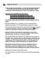
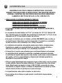
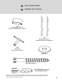
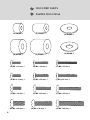
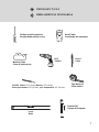
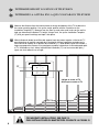
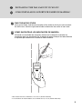
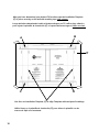
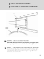
FLAT PANEL TV WALL MOUNT
INSTRUCTION MANUAL
SOPORTE DE PARED PARA TV
DE PANTALLA PLANA
MANUAL DE INSTRUCCIONES
9880GC
PRECAUTIONS
BE SURE TO READ THE ENTIRE MANUAL. IF AT ANY TIME YOU ARE UNCLEAR ABOUT
THE DIRECTIONS AND BELIEVE YOU NEED FURTHER ASSISTANCE, CONTACT
GENERATIONS™ INSTALLATION EXPERTS AT 888-779-1543 FROM 9AM – 5PM EST.
• NEVER EXCEED THE MAXIMUM LOAD CAPACITIES OF:
- 130 LBS (60 KG) FOR MOUNTING INTO WOOD STUDS
- 130 LBS (60 KG) FOR MOUNTING INTO CONCRETE WALLS
- 130 LBS (60 KG) FOR MOUNTING INTO CONCRETE BLOCK
• THIS PRODUCT SHOULD NEVER BE MOUNTED TO METAL FRAMING STUDS OR
BRICKS.
• Wood studs should be 2" x 4", at minimum: 1.5" X 3.5" (38 mm X 89 mm).
Designed to be mounted to 2" X 4" wood studs that are spaced 16" on center.
• This mounting bracket was designed to be installed and utilized ONLY as specified
in this manual. Generations will not be responsible for failure to assemble as
directed or for the improper assembly, use, or handling of this product.
• Improper installation of this product may cause damage or serious injury.
Generations cannot be liable for direct or indirect damage or injury caused by
incorrect mounting, incorrect use, or incorrect assembly.
• If the mounting bracket will be attached to any structure other than specified in
this manual, only a licensed professional contractor/installer should perform this
installation. The supporting structure must support, at minimum, four times the
combined weight of the mounting bracket and TV. It is the responsibility and
liability of the installer to ensure the suitability of the supporting structure.
• Check carefully to ensure that there are no missing or damaged parts. Never use
defective parts. If any parts are damaged or missing, call Customer Service at
888-779-1543 and parts will be shipped directly to the original purchaser. Please
contact Customer Service before attempting to return products to the point of purchase.
• Specifications are subject to change without notice.
• The maximum weight of your television cannot exceed the maximum weight rating of
your mount.
2
ADVERTENCIAS
ASEGÚRESE DE LEER TODO EL MANUAL DE INSTRUCCIONES. SI EN ALGÚN
MOMENTO TIENE DUDAS SOBRE LAS INSTRUCCIONES Y CREE NECESITAR ASISTENCIA
ADICIONAL, CONTÁCTESE CON LOS EXPERTOS EN INSTALACIÓN DE GENERATIONS
LLAMANDO AL 888-779-1543 DE 9 A.M. A 5 P.M., HORA DEL ESTE.
• NUNCA EXCEDA LA CAPACIDAD MÁXIMA DE CARGA DE:
- 130LBS (60KG) EN PAREDES CON MONTANTES DE MADERA
- 130LBS (60KG) EN PAREDES DE CONCRETO
- 130LBS (60KG) EN PAREDES DE BLOQUES DE CONCRETO
• ESTE PRODUCTO NUNCA DEBE SER MONTADO SOBRE MONTANTES METÁLICOS O
LADRILLOS.
• Los montantes de madera deben ser 2" X 4", un mínimo de 1,5" X 3,5" (38 mm X 89
mm). Diseñado para usar montado sobre montantes de madera de 2" x 4" (2,5 x 5 cm)
separados por 16" (2,5 cm) desde el centro de cada uno.
• Este soporte fue diseñado para ser instalado y utilizado ÚNICAMENTE como se indica en
el presente manual. Generations no se hará responsable si el producto no se ensambla
tal como se indica ni de su ensamblaje, uso o manejo incorrectos.
• La instalación incorrecta de este producto puede causar daños o lesiones graves.
Generations no puede ser responsabilizada por los daños o lesiones directos o
indirectos causados por el montaje, uso o ensamblaje incorrectos.
• Si desea fijar el soporte a una estructura que no está especificada en este manual,
la instalación deberá realizarla un contratista o instalador profesional autorizado.
La estructura de soporte debe soportar, como mínimo, cuatro veces el peso combinado
del soporte y el TV. Es responsabilidad y obligación del instalador garantizar la
idoneidad de la estructura de soporte.
• Revise el equipo detenidamente para asegurarse de que no falten piezas o que las mismas
no estén dañadas. Nunca utilice piezas defectuosas. Si alguna pieza falta o está dañada,
llame a Departamento de atención al cliente al 888-779-1543 y se enviarán las piezas
directamente al comprador Original. Contáctese con Departamento de atención al cliente
antes de intentar devolver los productos en el punto de compra.
• Las especificaciones están sujetas a cambios sin previo aviso.
• El peso máximo de su televisor no puede exceder la clasificación de peso máximo
de su soporte.
3
INCLUDED PARTS
PARTES INCLUIDAS
(EA)
Extension Arm, 1
Brazo de extensión, 1
(MA)
Monitor Arms, 2
Brazos de la pantalla, 2
(TC)
Top Rail Cover, 1
Cubierta del riel superior, 1
(BC)
Bottom Rail Cover, 1
Cubierta del riel inferior, 1
(IT)
Installation Template, 1
Plantilla de instalación, 1
4
INCLUDED PARTS
PARTES INCLUIDAS
(CC)
Cable Management Cover, 1
Cubierta del administrador de cables, 1
(AC)
Monitor Arm Covers, 2
Cubiertas de brazos para pantalla, 2
(HT)
Hex Tool, 1
Herramienta hexagonal, 1
(BW) M8, 4
(BT) M8 X 63 mm, 4
(AU) TOGGLER® brand A10
ALLIGATOR® Anchor, 4
TOGGLER® brand ALLIGATOR® SOLID-WALL ANCHORS are patented under one or more of US Patent numbers 5,161,296 and
5,938,385; and foreign counterparts thereof and of 4,752,170. Other patents pending. TOGGLER and ALLIGATOR are worldwide
registered trademarks of Mechanical Plastics Corp.
5
INCLUDED PARTS
PARTES INCLUIDAS
6
(D) M4/M5, 4
(E) M4/M5, 4
(Q) M6/M8, 4
(P) M6/M8, 4
(R) M4/M5, 4
(S) M6/M8, 4
(A) M4 x 12 mm, 4
(B) M4 x 22 mm, 6
(C) M4 x 30 mm, 4
(G) M5 x 12 mm, 4
(H) M5 x 22 mm, 4
(I) M5 x 30 mm, 4
(J) M6 x 14 mm, 4
(K) M6 x 25 mm, 4
(L) M6 x 35 mm, 6
(M) M8 x 20 mm, 4
(N) M8 x 30 mm, 4
(O) M8 x 40 mm, 4
NECESSARY TOOLS
HERRAMIENTAS NECESARIAS
Phillips-head Screwdriver
Destornillador philips (cruz)
Masking Tape
Cinta de enmascarar
Stud Finder
Localizador de montantes
Drill
Taladro
Drill Bit: Wood: 1/4" (6.5 mm), Masonry: 3/8" (9.5 mm)
Broca para madera: 1/4" (6.5 mm), para mampostería: 3/8" (9.5 mm)
Level
Nivel
Pencil
Lápiz
Tape Measure
Cinta métrica
Ratchet Set
Equipo de trinquete
7
DETERMINE HEIGHT LOCATION OF TELEVISION
DETERMINE LA ALTURA EN LA QUE COLOCARÁ EL TELEVISOR
Measure the distance from the bracket holes to the top and bottom of the TV to determine
the center mounting position. Line up the center position with the Centerline on the
Installation Template (IT). Measure from the floor up, and make small marks on the wall to
help you determine the desired TV height. Using a level, line up the Installation Template
(IT) with your pencil markings and tape it into place.
Mida la distancia desde los orificios del soporte hasta las partes superior e inferior del TV
para determinar la posición centrada de la instalación. Alinee la posición centrada con la
línea central de montaje en la plantilla de instalación (IT). Mida desde el piso hacia arriba y
haga unas pequeñas marcas en la pared para ayudarle a determinar la altura deseada para
el TV. Utilizando un nivel, alinee la plantilla de instalación (IT) con las marcas del lápiz y
sujete con cinta adhesiva en el lugar.
IT
• Height to center of TV
• Altura para centrar el TV
8
FOR MASONRY INSTALLATIONS, SEE PAGE 12.
PARA INSTALACIONES EN MAMPOSTERÍA CONSULTE LA PÁGINA 12.
INSTALLING THE WALL MOUNT IN WOOD*
CÓMO INSTALAR EL SOPORTE DE PARED EN MADERA*
FIND THE WOOD STUDS
Using a stud finder, find the exact location of the studs to which you want to attach
the wall mount. Mark the right and left side to determine the center of each stud.
CÓMO ENCONTRAR LOS MONTANTES DE MADERA
Utilizando un localizador de montantes, determine la ubicación exacta de los
montantes sobre los que desea fijar el soporte de pared. Marque los lados derecho
e izquierdo para determinar el centro de cada montante.
* Wood studs must be a minumum of 1.5" X 3.5" (38 mm X 89 mm)
* Los montantes de madera deben ser un mínimo de 1,5" X 3,5" (38 mm X 89 mm)
9
After you have determined your desired TV location, tape the Installation Template
(IT) in place securely on the wall with masking tape. Use a Level.
Luego de haber determinado la ubicación deseada para su TV, utilice cinta adhesiva
para sujetar la plantilla de instalación (IT) a la pared de forma segura. Utilice un nivel.
A
B
IT
C
D
Use lines on Installation Template (IT) to align Template with stud pencil markings.
Utilice líneas en la plantilla de instalación (IT) para alinear la plantilla con las
marcas de lápiz en el montante.
10
DRILL PILOT HOLES
Follow directions on the Installation Template (IT) carefully. Drill four
holes 3" (77 mm) deep using a 1/4" (or 6.5 mm) size drill bit in the
“A”, “B”, “C” and “D” locations noted on the Installation Template.
TALADRE ORIFICIOS GUÍA
Siga atentamente las instrucciones de la plantilla de instalación (IT).
Taladre cuatro orificios de 3" (77 mm) de profundidad con una broca
de 1/4" (6.5 mm) en las ubicaciones "A", "B", "C" y "D" apuntadas en
la plantilla de instalación.
11
MOUNTING TO SOLID CONCRETE OR CINDER BLOCK
MONTAJE EN CONCRETO SÓLIDO O LADRILLOS DE ESCORIAS
Level
Nivel
IT
A
C
B
D
dO NOT dRILL INTO MORTAR jOINTS! dRILL hOLES AT LEAST 1" (25.4 MM) FROM
ThE jOINTS. USE A NEW dRILL bIT TO ENSURE OPTIMUM hOLdING AbILITY.
dO NOT USE A hAMMER dRILL!
NO PERFORE LAS jUNTAS dE ARGAMASA. TALAdRE ORIFICIOS A UNA dISTANCIA
dE, POR LO MENOS, 1" (25,4 MM) dE LAS jUNTAS. USE UNA bROCA NUEVA PARA
GARANTIzAR UNA CAPACIdAd óPTIMA dE SUjECIóN. NO USE UN TALAdRO
PERCUTOR.
12
DRILL PILOT HOLES
Carefully drill four holes using a 3/8" (or 9.5 mm) masonry drill bit in
the “A”, “B”, “C” and “D” locations noted on the Installation Template.
Each hole should be at least 3-3/4" (95 mm) deep.
TALADRE ORIFICIOS GUÍA
Taladre cuatro orificios con una broca de 3/8" (9.5 mm) para mampostería en las
0ubicaciones "A", "B", "C" y "D" apuntadas en la plantilla de instalación.
Cada orificio debe tener, por lo menos, 3-3/4" (95 mm) de profundidad.
AU
INSERT ANCHORS
Remove Template (IT) and insert TOGGLER® brand ALLIGATOR® Anchors (AU).
COLOQUE LOS ANCLAJES
Quite la plantilla (IT) y coloque los anclajes (AU) marca TOGGLER® Y ALLIGATOR®.
13
INSTALL THE EXTENSION ARM (EA)
Remove the Installation Template from the wall. Make sure the Extension Arm (EA) is fully
extended as shown, and align the holes in the top and bottom rails with the holes in the
wall. Have an assistant help you support the mount if necessary. Insert all four Lag Bolts
(BT) with M8 Washers (BW) and tighten fully. be careful not to overtighten Lag bolts!
INSTALACIÓN DEL BRAZO DE EXTENSIÓN (EA)
Quite la plantilla de instalación de la pared. Asegúrese de que el brazo de extensión (EA)
esté extendido por completo, tal como se muestra, y alinee los orificios de los rieles
superior e inferior con los orificios de la pared. Si es necesario, pida a un ayudante que le
ayude a sostener la montura. Inserte los cuatro tirafondos (BT) con arandelas M8 (BW) y
apriételos por completo. ¡Tenga cuidado de no apretar los tirafondos demasiado!
BW
BT
EA
DO NOT OVER TIGHTEN LAG BOLTS (BT)!
NO AJUSTE DEMASIADO LOS TIRAFONDOS (BT)!
BW
BT
AU
EA
14
ATTACH THE RAIL COVERS (TC, BC)
Add Each Rail Cover (TC and BC) as shown by snapping them over the wall rails.
To remove the Top Rail Cover (TC), grasp the Cover at the ends and carefully lift the
bottom of the Rail Cover in an upward motion. To remove the Bottom Rail Cover (BC), press
the top of the Cover down at the locations shown to release the tabs and then pull out in a
downward motion.
CÓMO COLOCAR LAS CUBIERTAS DE RIEL (TC, BC)
Coloque cada cubierta de riel (TC y BC) encajándolas sobre los rieles de pared, tal como
se muestra.
Para retirar la cubierta del riel superior (TC), sujétela por sus extremos y levante con cuidado
la parte inferior de la cubierta del riel con un movimiento ascendente. Para retirar la cubierta
del riel inferior (BC), presione hacia abajo la parte superior de la cubierta en las zonas
indicadas para liberar las pestañas, luego tire hacia afuera con un movimiento descendente.
TC
1
EA
2
BC
15
ATTACHING THE MONITOR ARMS (MA)
CÓMO FIJAR LOS BRAZOS DE LA PANTALLA (MA)
SELECT THE CORRECT SCREW
Before beginning, test several of the screws in your hardware kit to find the
correct size and length for your television.
ELIJA EL TORNILLO CORRECTO
Antes de comenzar, pruebe varios tornillos de su kit de accesorios para encontrar
el de tamaño y longitud indicados para su televisor.
MONITOR ARM (MA)
BRAZO DE LA PANTALLA (MA)
SPACER
ESPACIADOR
WASHER
ARANDELA
(MA)
(MA)
(MA)
TELEVISION
16
TELEVISOR
MA
DO NOT OVER TIGHTEN SCREWS!
NO AJUSTE DEMASIADO LOS TORNILLOS.
ATTACHING THE MONITOR ARMS (MA)
Attach each Monitor Arm (MA) to the back of your television as shown. Make sure that
each Washer (R for M4 or M5 screws, or S for M6 or M8 screws) is placed between the
Screw and the Monitor Arm. don’t place the Washers between the Arms and the
television.
CÓMO FIJAR LOS BRAZOS DE LA PANTALLA (MA)
Conecte cada brazo de la pantalla (MA) a la parte trasera de su televisor tal como se
muestra. Asegúrese de que cada arandela (R para tornillos M4 o M5 o S para tornillos M6
o M8) esté colocada entre el tornillo y el brazo de la pantalla. No coloque las arandelas
entre los brazos y el televisor.
17
MA
DO NOT OVER TIGHTEN SCREWS!
NO AJUSTE DEMASIADO LOS TORNILLOS.
USING SPACERS
Use spacers if the Monitor Arms (MA) do not fit firmly against the back of the television, such as
when the back of the television is curved, contains larger recessed mounting holes, or some other
obstruction is in the way. Spacers also provide additional room for cables. The Monitor Arms must
rest securely on the spacers, and should not be loose.
USO DE LOS ESPACIADORES
Use los espaciadores si los brazos de la pantalla (MA) no encajan con firmeza contra la parte
trasera del televisor, como sucede cuando esta parte es curva, contiene orificios de montaje
embutidos más grandes o presenta alguna otra obstrucción. Los espaciadores también ofrecen
espacio adicional para cables. Los brazos deben apoyarse con firmeza sobre los espaciadores y
no deben quedar flojos.
18
MOUNTING THE TELEVISION
CÓMO INSTALAR EL TELEVISOR
MA
L
PREPARE THE SECRITY SCREWS
Adjust the Security Screws (L) in the Monitor Arms (MA) so that they do not interfere with
installation onto the Extension Arm (EA). Using a screwdriver, turn the Security Screws to
FULLY LOWER the locking component of the Security Screw as shown above.
PREPARE LOS TORNILLOS DE SEGURIDAD
Ajuste los tornillos de seguridad (L) en los brazos de la pantalla (MA) de manera que no
interfieran con la instalación en el brazo de extensión (EA). Con un destornillador, gire los
tornillos de seguridad para BAJAR POR COMPLETO el componente de bloqueo del tornillo
de seguridad, tal como se muestra arriba.
19
MA
EA
MOUNT THE TELEVISION
With the help of at least one assistant, lift the television and guide the Monitor
Arms (MA) onto the Extension Arm as shown.
CÓMO MONTAR EL TELEVISOR
Con la ayuda de, por lo menos, un asistente, levante el televisor y guíe los
brazos de la pantalla (MA) sobre el brazo de extensión, tal como se muestra.
20
SECURE THE TELEVISION
Once safely on the mount, secure the television by tightening the Security Screws (L)
using a Phillips-head screwdriver as shown. Repeat on both sides.
Loosen this Screw to remove television. Exercise caution when removing the television
from the mount to avoid equipment damage or personal injury.
CÓMO ASEGURAR EL TELEVISOR
Una vez que lo colocó con seguridad sobre el soporte, fije el televisor con los tornillos
de fijación (L) utilizando un destornillador de punta Phillips. Repítalo con el otro
extremo.
Suelte este tornillo para quitar la televisión. Tenga mucho cuidado al retirar el televisor
del soporte para evitar daños en el equipo o lesiones corporales.
MA
L
21
ATTACHING THE DECORATIVE ARM COVERS
CÓMO COLOCAR LAS CUBIERTAS DECORATIVAS
MA
AC
AC
MA
ATTACH THE PLASTIC ARM COVERS (AC)
Align the Monitor Arm Covers (AC) with the backs of the Monitor Arms (MA) as shown
and press into place as shown in the illustration.
UNA LAS CUBIERTAS PLÁSTICAS PARA LOS BRAZOS (AC)
Alinee las cubiertas para los brazos del monitor (AC) con la parte trasera de los brazos
del monitor (MA), tal como se muestra, y presiónelas para colocarlas en su lugar, como
se ve en la ilustración.
22
ADJUSTING THE TELEVISION POSITIONING
CÓMO AJUSTAR LA POSICIÓN DEL TELEVISOR
ADJUSTING THE LEVEL OF THE TELEVISION
Using the Hex Tool (HT), LOOSEN (dO NOT REMOVE!) the Nuts on the back of
the wall mount’s monitor plate as shown in the illustration. Level the TV, then
tighten the Nuts.
CÓMO AJUSTAR EL NIVEL DEL TELEVISOR
Con una herramienta hexagonal (HT), AFLOJE (¡PERO NO QUITE!) las tuercas
de la parte trasera de la placa del monitor del soporte de pared, tal como se ve en
la ilustración. Nivele el TV y luego, ajuste las tuercas.
TO ADJUST TV LEVEL, LOOSEN (BUT DO NOT REMOVE) NUTS
PARA AJUSTAR EL NIVEL, AFLOJE LAS TUERCAS (PERO NO LAS QUITE)
23
ADJUSTING THE TILT
NOTE: One or two people should hold the TV as you adjust the tilt position.
While holding the TV, gently pull down on the Tilt Cord to release the locking mechanism.
Position the TV to the desired position, then release the Tilt Cord to lock into place.
To return the television to an upright position, simply push the TV upward and into place.
You do not need to pull the Tilt Cord again to tilt backward.
AJUSTE DE LA INCLINACIÓN
NOTA: Una o dos personas deben sostener el TV mientras usted ajusta la posición de
la inclinación. Mientras sostienen el TV, jale suavemente del cordón de inclinación para
liberar el mecanismo de bloqueo. Ubique el TV en la posición deseada, luego suelte el cable
de inclinación para bloquearlo en su lugar. Para regresar el televisor a la posición vertical,
simplemente empújelo hacia arriba hasta que quede en su lugar. No es necesario volver a
jalar del cordón para inclinarlo hacia atrás.
24
USING THE CABLE MANAGEMENT
CÓMO USAR LA ADMINISTRACIÓN DE CABLES
EA
CABLES
CABLES
USING THE CABLE MANAGEMENT FEATURE
Feed the Audio Video cables through the Cable Management Cover as shown. Attach
the Cover to the bottom portion of the Extension Arm (EA) by pressing upward until the
Cover snaps into place. Remove extra cables if the Cover will not properly attach.
USO DE LA CARACTERÍSTICA DE ADMINISTRACIÓN DE CABLES
Pase los cables de audio y vídeo a través de la cubierta de administración de cables,
tal como se muestra. Fije la cubierta a la parte inferior del brazo de extensión (EA)
presionándola hacia arriba hasta que la cubierta encaje en su lugar. Si no se fija
correctamente, quite los cables extra.
25
LIMITED LIFETIME WARRANTY
[Please note: You are responsible to inspect your mount thoroughly for missing or defective parts immediately after
opening the box. To receive replacement or missing part(s) under this Warranty, call our Customer Service
Department at 1-888-779-1543. Please have the model number, date code, part number(s) and your sales receipt or
other proof of purchase available for reference. We will ship you any necessary replacement parts in the United States
without charge at our expense.]
This Generations (“Generations” or “we”) mounting product, manufactured exclusively for PC Richard & Son,
SKU 9880GC (“Product”) is warranted for the life of the Product only to the original purchaser and limited to
the originalinstallation (“Warranty”). Re-installation of the Product in a different location or with a different
monitor or peripheral voids this Warranty. This Warranty is only valid in the United States of America.
We warrant to the original purchaser that the Product and all parts and components thereof are free of
defects in material and workmanship. “Defects”, as used in this Warranty, is defined as any imperfections that
impair the use of the Product.
Our Warranty is expressly limited to replacement of mount parts and components. We will replace any part
listed on the enclosed mount parts sheet that is defective in material or workmanship only to the original
owner within the limitations stated herein.
This Warranty applies only under conditions of normal use. The Product is not intended for outdoor use.
This Warranty does not cover: 1) defects caused by improper installation or disassembly; 2) defects caused by
shipping (claims for damage during transit to you should be made immediately by you directly to the
transportation company); 3) defects occurring after purchase due to modification, intentional damage,
accident, misuse, abuse, negligence, natural disaster, abnormal mechanical or environmental conditions,
unauthorized disassembly, repair, modification or exposure to the elements; 4) cosmetic damage and 5) labor
or assembly costs.
This Warranty does not apply if the Product has been repackaged or resold as second-hand.
There are no warranties, express or implied, including without limitation merchantability or fitness for
particular use, except as (i) contained herein or (ii) required by applicable law in the state whose law
governs. The substantive and procedural law of the State of New Jersey shall govern this Warranty, absent
controlling law imposing the law of another state in lieu thereof as governing law. New Jersey Superior Court
or the United States District Court for the District of New Jersey, as appropriate, shall retain exclusive
jurisdiction over enforcement of this Warranty and all subject matter hereof. All warranties of whatsoever
derivation shall be limited to the terms set forth herein, unless otherwise required by applicable law.
You shall not rely on manufacturers’, employees’ or representatives’ statements, whether oral or written,
which neither modify this Warranty nor are they part of either your purchase contract or this Warranty.
Except as provided herein, there is has no liability or responsibility to you or any other person or entity with
respect to any liability, loss or damage caused directly or indirectly by use of the Product, including, but not
limited to, any incidental or consequential damages. Some states do not allow limitation on how long an
implied warranty can last or the exclusion or limitation of incidental or consequential damages. Therefore,
the above limitations and exclusion may not apply to you.
This Warranty covers only repair or replacement for this mount as stated above.
This Warranty gives you specific legal rights. You may also have other rights, which vary from state to state.
26
GARANTÍA LIMITADA DE POR VIDA
[Nota: usted tiene la responsabilidad de inspeccionar el soporte cuidadosamente para detectar piezas faltantes o
defectuosas inmediatamente después de abrir la caja. Para recibir las piezas faltantes o de repuesto cubiertas por
esta Garantía, llame a nuestro Departamento de atención al cliente al 1-888-779-1543. Tenga a mano a modo de
referencia el número de modelo, el código de fecha, el(los) número(s) de pieza(s) y la factura u otro comprobante
de compra. Le enviaremos cualquier pieza de repuesto necesaria, en los Estados Unidos, sin costo alguno, a cargo
de la empresa.]
Este producto de soporte de Generations (“Generations” o “nosotros”), fabricado exclusivamente para
P. C. Richard & Son, con SKU (código de stock) 9880GC (“Producto”) tiene garantía durante la vida del
Producto sólo para el comprador original y se limita a la instalación original (“Garantía”). La reinstalación
de este Producto en otro lugar o con una pantalla o accesorios diferentes anula esta Garantía. Esta Garantía
sólo es válida en los Estados Unidos.
Garantizamos al comprador original que el Producto y todas sus piezas y componentes no presentan defectos
materiales ni de fabricación. Según esta Garantía, el término “defectos” se define como toda imperfección
que impida el uso del Producto.
Nuestra Garantía se limita expresamente al reemplazo de los componentes y piezas de soporte. Vamos a
reemplazar toda pieza que figure en la hoja adjunta de piezas de soporte y que presente defectos materiales o
de fabricación, sólo a favor del comprador original dentro de las limitaciones aquí declaradas.
Esta Garantía sólo tiene validez en condiciones normales de uso. El Producto no debe utilizarse al aire libre.
Esta Garantía no cubre: 1) defectos ocasionados por la instalación o el desmontaje incorrectos; 2) defectos
ocasionados por el envío (usted deberá reclamar inmediata y directamente ante la empresa de transporte por
los daños ocurridos cuando se le envíe el Producto a usted); 3) defectos que surgen después de la compra
debido a cambios, daños intencionales, accidentes, uso incorrecto, abuso, negligencia, catástrofe, condiciones
mecánicas o ambientales anormales, desmontaje no autorizado, reparaciones, modificaciones o exposición a
los elementos; 4) daños estéticos y 5) costos de montaje o mano de obra.
Esta Garantía no tiene validez si el Producto ha sido empaquetado o vendido nuevamente como usado.
No existen garantías, explícitas o implícitas, que incluyan ilimitadamente la comercialización o idoneidad para
un fin determinado, excepto según (i) se establece en la presente garantía o (ii) lo exige la ley vigente del estado
cuyas leyes rigen. El derecho sustantivo y procesal del Estado de Nueva Jersey regirá esta Garantía y, en ausencia
de la ley que regule, se impondrá la ley de otro estado en su lugar como ley vigente. El Tribunal Superior de
Nueva Jersey o el Tribunal de Distrito de los Estados Unidos en el Distrito de Nueva Jersey, según corresponda,
conservarán la jurisdicción exclusiva sobre la ejecución de esta Garantía y todo tema relacionado. Todas las
garantías de cualquier origen se limitarán a los términos aquí establecidos, salvo disposición contraria de la ley
vigente.
Usted no debe confiar en las declaraciones de los fabricantes, empleados o representantes, tanto orales como
escritas, las cuales no modifican esta Garantía ni forman parte de su contrato de compra o de esta Garantía.
Salvo lo dispuesto en esta garantía, No hay tiene ninguna obligación ni responsabilidad hacia usted u otra
persona con respecto a cualquier obligación, pérdida o daño causado directa o indirectamente por el uso del
Producto, lo que incluye, entre otros, los daños fortuitos o emergentes. Algunos estados no permiten limitar
la duración de una garantía implícita o la exclusión o limitación de los daños fortuitos o emergentes. Por
consiguiente, es posible que la exclusión y las limitaciones antes mencionadas no sean válidas en su caso.
Esta Garantía sólo cubre la reparación o el reemplazo de este soporte, según lo dispuesto anteriormente.
Esta Garantía le otorga derechos legales específicos. Usted también puede tener otros derechos, los cuales
varían de un estado a otro.
27
1E_0913A