1
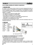
V2 S.p.A.
Corso Principi di Piemonte, 65/67 - 12035 RACCONIGI (CN) ITALY
tel. +39 01 72 81 24 11
[email protected]
fax +39 01 72 84 050
www.v2home.com
ML6
I
GB
MODULO MULTITENSIONE A LED
MULTIVOLTAGE LED MODULE
F
MODULE MULTI-TENSION À DEL
E
MÓDULO MULTITENSIÓN DE LED
P
MÓDULO MULTITENSÃO COM LED
D
MULTISPANNUNGS- LED- MODUL
NL
MULTI-SPANNINGSMODULE MET LEDS
IL n. 368
EDIZ. 10/04/2012
ITALIANO
ML6 è un modulo multitensione a led realizzato per sostituire le
normali lampadine a incandescenza all’interno dei lampeggianti
già installati.
•
Tecnologia multitensione per adattare il modulo a tutti i tipi
di lampeggianti
Connettore a vite per l’installazione del modulo ML6 sugli
attacchi E14
Morsettiera estraibile per evitare torsioni dei cavi
durante le fasi di installazione
•
•
SMALTIMENTO
Come per le operazioni d’installazione, anche al termine della
vita di questo prodotto, le operazioni di smantellamento devono
essere eseguite da personale qualificato.
Questo prodotto è costituito da vari tipi di materiali: alcuni
possono essere riciclati, altri devono essere smaltiti.
Informatevi sui sistemi di riciclaggio o smaltimento previsti dai
regolamenti vigenti nel vostro territorio, per questa categoria di
prodotto.
AVVERTENZE IMPORTANTI
Attenzione! L’installazione del prodotto deve essere effettuata da
personale qualificato, nel rispetto di leggi e norme vigenti sul
territorio e delle istruzioni contenute in questo manuale.
È importante rispettare le seguenti avvertenze:
• Il dispositivo deve essere installato all’interno di contenitori
ermetici con grado di protezione pari o superiore a IP44.
c
ATTENZIONE: quando il dispositivo è
collegato alla centrale di comando la scheda
ML6 è sotto tensione e non deve essere
toccata.
•
•
Prima di effettuare i collegamenti elettrici è
opportuno togliere tensione elettrica alla centrale.
•
Prima di eseguire qualsiasi operazione manuale sul
modulo ML6 è opportuno togliere tensione elettrica
alla centrale.
Verificare che la tensione di alimentazione del prodotto sia
compatibile con quella presente sui morsetti della centrale di
comando dedicati al collegamento del lampeggiante.
CARATTERISTICHE TECNICHE
Alimentazione
24 ÷ 300Vdc
24 ÷ 230Vac 50/60Hz
Intermittenza
automatica
Ciclo Max di funzionamento
Temperatura di funzionamento
Dimensioni
80%
-20 ÷ +60 °C
74 x 32 x 30 mm
INSTALLAZIONE
1. Togliere tensione elettrica alla centrale di comando
2. Aprire il contenitore del lampeggiante su cui dovrà
essere installato il modulo ML6
3. Svitare la lampadina
4. Avvitare il modulo sul lampeggiante
5. Scollegare i due morsetti del lampeggiante e collegarli
ai due morsetti del modulo
6. Posizionare il jumper J1:
- J1 inserito: lampeggio gestito dalla centrale di comando
- J1 NON inserito: lampeggio gestito dal lampeggiante
7. Chiudere ermeticamente il contenitore del lampeggiante
NOTA: l’attacco a vite serve solo per fissare il modulo,
l’alimentazione viene portata tramite i due cavi che arrivano
dalla centrale di comando sulla morsettiera estraibile.
DICHIARAZIONE DI CONFORMITÀ
V2 S.p.A. dichiara che le apparecchiature ML6 sono conformi ai
requisiti essenziali fissati dalle direttive:
2004/108/CEE
2006/95/CEE
COMPATIBILITÀ ELETTROMAGNETICA
BASSA TENSIONE
Racconigi, 01/04/2012
Il rappresentante legale V2 S.p.A.
Cosimo De Falco
ENGLISH
ML6 is a LED multivoltage module designed to replace standard
incandescent bulbs inside the flashing lights already installed.
•
Multivoltage technology to adapt the module to all types of
flashing lights
Screw connectors to install the module ML6 on the
attachments E14
Removable terminal panel to avoid cable torsion during
installation
•
•
DISPOSAL
As for the installation, the disposal of the product at the end of
its effective life must be performed by qualified personnel.
This product is made of various types of material, some of
which can be recycled while others must be disposed of.
Enquire about the recycling or disposal systems available for
this product category in compliance with regulations locally in
force.
IMPORTANT WARNING
Warning! The installation of the product has to be made by
qualified personnel, under the laws and rules in force and
following the instructions of this handbook.
It is important to respect the following warnings:
• The device must be installed inside hermetical containers with
protection degree equal or higher than IP44.
c
ATTENTION: when the device is
connected to the control unit, the board ML6
is energized and must not be touched.
•
•
Before performing electric connections, it is
recommended to turn off the power supply to the
control unit.
•
Before performing any manual operation on module
ML6, it is recommended to turn off the power supply
to the control unit.
Check that the voltage of the product is compatible with the
one on the clamp of the control unit used for the connection
of the flashing light.
TECHNICAL FEATURES
Power supply
24 ÷ 300Vdc
24 ÷ 230Vac 50/60Hz
Intermittence
automatic
Max working cycle
Working temperature
Dimensions
80%
-20 ÷ +60 °C
74 x 32 x 30 mm
INSTALLATION
1. Turn off the power supply to the control unit.
2. Open the container of the flashing light where module ML6 shall
be installed
3. Unscrew the bulb
4. Screw the module on the flashing light
5. Disconnect the two terminals of the flashing light and connect
them to the two terminals of the module
6. Position jumper J1:
- J1 inserted: flashing controlled by the control unit
- J1 NOT inserted: flashing controlled by the flashing light
7. Hermetically close the flashing light container
NOTE: the purpose of the screw attachment is just to fasten
the module, the supply is provided by the two cables arriving
from the control unit on the removable terminal panel.
DECLARATION OF CONFORMITY
V2 S.p.A. hereby declare that ML6 equipment conforms to the
essential requirements established in the directive
2004/108/CEE
2006/95/CEE
ELECTROMAGNETIC COMPATIBILITY
LOW VOLTAGE DIRECTIVE
Racconigi, 01/04/2012
Legal representative, V2 S.p.A.
Cosimo De Falco
FRANÇAIS
ML6 est un module multi-tension à DEL réalisé pour remplacer les
normales ampoules à incandescence à l'intérieur des feux à éclats
déjà installés.
•
Technologie multi-tension pour adapter le module à tous les
types de feux à éclats
Connecteur à vis pour l'installation du module ML6 sur les
culots E14
Bornier extractible pour éviter la torsion des câbles durant les
phases d'installation
•
•
MISE AU REBUT
Comme pour l’installation, à la fin de la durée de vie de ce
produit, les opérations de démantèlement doivent être effectuées
par du personnel qualifié.
Ce produit est constitué de différents types de matériaux :
certains peuvent être recyclés, d’autres doivent être mis au rebut.
Informez-vous sur les systèmes de recyclage ou de mise au rebut
prévus par les normes en vigueur dans votre région pour cette
catégorie de produit.
NOTICES IMPORTANTES
Attention! L’installation du produit doit être effectuée par
personnel qualifié dans le respect des lois et normes en force
dans le territoire et de ce mode d’emploie.
Il est important de respecter les notices suivantes :
• Le dispositif doit être installé à l'intérieur de conteneurs
hermétiques avec degré de protection égal ou supérieur à IP44.
c
ATTENTION: lorsque le dispositif est
connecté à la centrale de commande la carte
ML6 est sous tension et ne doit pas être
touchée.
•
•
Avant d'effectuer les raccordements électriques il est
opportun de couper la tension électrique à la centrale.
•
avant d'effectuer toute opération manuelle sur le
module ML6 il est opportun de couper la tension
électrique à la centrale.
Vérifier que la tension d’alimentation du produit soit
compatible avec celle des bornes de l’armoire de commande
dédiés à la connexion du feux.
CARACTERISTIQUES TECNIQUES
Alimentation
24 ÷ 300Vdc
24 ÷ 230Vac 50/60Hz
Intermittence
automatic
Cycle max de fonctionnement
Température de fonctionnement
Dimensions
80%
-20 ÷ +60 °C
74 x 32 x 30 mm
INSTALLATION
1. Couper la tension électrique à la centrale de commande
2. Ouvrir le conteneur du feu à éclats sur lequel on devra installer
le module ML6
3. Dévisser l'ampoule
4. Visser le module sur le feu à éclats
5. Débrancher les deux bornes du feu à éclats et les raccorder aux
deux bornes du module
6. Positionner le shunt J1:
- J1 branché: clignotement géré par la centrale de commande
- J1 NON branché: clignotement géré par le feu à éclats
7. Fermer hermétiquement le conteneur du feu à éclats
REMARQUE: le culot à vis sert seulement à fixer le module,
l’alimentation est amenée par les deux câbles provenant de la
centrale de commande sur le bornier extractible.
DÉCLARATION DE CONFORMITÉ
V2 S.p.A. déclare que les produits ML6 sont conforment aux
qualités requises essentielles fixées par la directive:
2004/108/CEE
2006/95/CEE
COMPATIBILITÉ ELECTROMAGNÉTIQUE
DIRECTIVE BASSE TENSION
Racconigi, 01/04/2012
Le représentant légal V2 S.p.A.
Cosimo De Falco
ESPAÑOL
ML6 es un módulo multitensión de led realizado para construir
las comunes lámparas de incandescencia dentro de las luces
intermitentes ya instalados.
•
Tecnología multitensión para adaptar el módulo a todas las
luces intermitentes
Conector de tornillo para montar el módulo ML6 en las
uniones E14
Tablero de bornes a extraer para evitar torsiones de los cables
durante las etapas de montaje
•
•
ADVERTENCIAS IMPORTANTES
Atención! La instalación del producto tiene que efectuarse para
técnicos especializados, en la observancia de las leyes y normas
vigentes en el territorio y de las instrucciones contenidas en este
manual.
Es importante respetar las advertencias siguientes:
• El dispositivo debe ser montado dentro de recipientes
herméticos con grado de protección igual o superior a IP44.
c
CUIDADO: cuando el dispositivo está
unido a la central de mando la tarjeta ML6
está en tensión y no debe tocarse.
•
•
Antes de realizar las conexiones eléctricas es
oportuno cortar la tensión eléctrica a la central.
•
Antes de realizar cualquier operación manual en el
módulo ML6 è oportuno cortar la tensión eléctrica a
la central.
Averiguar que la tensión de alimentación del producto sea
compatible con la presente en los bornes del cuadro de
maniobras para la conexión de la lámpara de señalización
CARACTERÍSTICAS TÉCNICAS
Alimentación
24 ÷ 300Vdc
24 ÷ 230Vac 50/60Hz
Intermitencia
automática
Ciclo Máx de funcionamiento
Temperatura de funcionamiento
Dimensiones
80%
-20 ÷ +60 °C
74 x 32 x 30 mm
MONTAJE
1. Corte la tensión eléctrica a la central de mando
2. Abra el recipiente de l a luz intermitente en el que tendrá que
montarse el módulo ML6
3. Destornille la bombilla
4. Enrosque el módulo de la luz intermitente
5. Desconecte los dos bornes de la luz intermitente y los conecte a
los dos bornes del módulo
6. Posicione el puente J1:
- J1 insertado: destello mandado por la central de mando
- J1 NO insertado: destello mandado por la luz intermitente
7. Cierre herméticamente el recipiente de la luz intermitente
NOTA: la unión de tornillo sólo sirve para fijar el módulo, la
alimentación se suministra mediante dos cables que llegan de
la central de mando en el tablero de bornes a extraer.
DESGUACE
Al igual que para las operaciones de instalación, también al final
de la vida útil de este producto, las operaciones de desguace
deben ser efectuadas por personal experto.
Este producto está formado de varios tipos de materiales: algunos
pueden reciclarse y otros deben eliminarse. Infórmese
sobre los sistemas de reciclaje o eliminación previstos por las
normas locales vigentes para esta categoría de producto.
DECLARACIÓN DE CONFORMIDAD
V2 S.p.A. declara que los productos ML6 cumplen los requisitos
esenciales establecidos por la siguiente directiva:
2004/108/CEE
2006/95/CEE
COMPATIBILIDAD ELECTROMAGNÉTICA
DIRECTIVA BASSE TENSION
Racconigi, 01/04/2012
El representante legal de V2 S.p.A.
Cosimo De Falco
PORTUGUÊS
ML6 é um módulo multitensão com LED realizado para substituir
as lâmpadas normais de incandescência no interior dos
indicadores intermitentes já instalados.
•
Tecnologia multitensão para adaptar o módulo a todos os
tipos de indicadores intermitentes
Conector com parafuso para instalação do módulo ML6 nas
ligações E14
Placa de terminais extraível para evitar torsões dos cabos
durante as fases de instalação
•
•
AVISOS IMPORTANTES
Atenção! A instalação do produto deve ser efectuada por um
técnico especializado segundo as leis e normas locais em vigor e
com base nas instruções fornecidas neste manual.
É importante respeitar os seguintes avisos:
DESMANTELAMENTO
Como na instalação, mesmo após a vida útil deste produto, as
operações de desmantelamento devem ser realizadas por pessoal
qualificado.
Este produto é constituído por diversos tipos de materiais: alguns
podem ser reciclados, outros devem ser eliminados.
Indague sobre a reciclagem ou eliminação nos termos da
regulamentação na sua área para esta categoria de produto.
DECLARAÇÃO DE CONFORMIDADE
V2 S.p.A. declara que as aparelhagens ML6 são conformes aos
requisitos essenciais estabelecidos pela directiva
2004/108/CEE
•
O dispositivo deve ser instalador dentro de contentores
herméticos com grau de protecção igual ou superior a IP44.
c
ATENÇÃO: quando o dispositivo está
ligado à central de comando, a placa ML6 está
sob tensão e não deve ser tocada.
•
•
Antes de efectuar as ligações eléctricas, é
recomendável desligar a tensão eléctrica na central.
•
Antes de executar qualquer operação manual no
módulo ML6, é recomendável desligar a tensão
eléctrica na central.
Verificar se a tensão de alimentação do produto é compatível
com a dos bornes do quadro eléctrico para a ligação da luz
de sinalização.
CARACTERÍSTICAS TÉCNICAS
Alimentação
24 ÷ 300Vdc
24 ÷ 230Vac 50/60Hz
Intermitência
automática
Ciclo máx. de funcionamento
Temperatura de funcionamento
Dimensões
80%
-20 ÷ +60 °C
74 x 32 x 30 mm
INSTALAÇÃO
1. Desligar a tensão eléctrica na central de comando
2. Abrir o contentor do indicador intermitente no qual deve ser
instalado o módulo ML6
3. Desapertar a lâmpada
4. Apertar o módulo no indicador intermitente
5. Desligar os dois terminais do indicador intermitente e ligá-los aos
dois terminais do módulo
6. Posicionar o jumper J1:
- J1 inserido: intermitência gerida pela central de comando
- J1 NÃO inserido: intermitência gerida pelo indicador
7. Fechar hermeticamente o contentor do indicador intermitente
NOTA: a ligação com parafuso serve apenas para fixar o
módulo, a alimentação é conduzida através dos dois cabos que
chegam da central de comando à placa de terminais extraível.
2006/95/CEE
DIRECTIVA COMPATIBILIDADE
ELECTROMAGNÉTICA
DIRECTIVA BASSE TENSION
Racconigi, 01/04/2012
O representante legal V2 S.p.A.
Cosimo De Falco
DEUTSCH
ML6 ist ein Multispannungs- Led-Modul, das als Ersatz für die
normalen Glühlampen in bereits installierten Blinkleuchten
realisiert wurde.
•
Multispannungs-Technologie zur Anpassung des Moduls an
alle Arten von Blinkleuchten
Schraubverbinder zur Installation des Moduls ML6 an
Anschlüssen E14
Klemmleiste ausziehbar, um das Verdrillen der Kabel während
der Installation zu vermeiden
•
•
WICHTIGE HINWEISE
Achtung! Die Installation des Produkts muss von qualifiziertem
Personal unter Berücksichtigung der lokal geltenden Gesetze und
Bestimmungen sowie der in diesem Handbuch enthaltenen
Hinweise erfolgen.
Es ist wichtig, folgende Hinweise zu beachten:
• Das Gerät muss in dichten Gehäusen mit Mindest-Schutzart
IP44 oder höher installiert werden.
c
ACHTUNG: wenn das Gerät an der
Steuerung angeschlossen ist, steht die Karte
ML6 unter Spannung und darf nicht berührt
werden.
•
•
Vor Ausführung der elektrischen Anschlüsse muss die
Stromversorgung der Steuerung unterbrochen werden.
•
Vor Ausführung von Arbeiten jeglicher Art am Modul
ML6 muss die Stromversorgung der Steuerung
unterbrochen werden.
Sicherstellen, dass die Versorgungsspannung des Produkts mit
derjenigen der Klemmen für den Anschluss des Blinklichts an
der Steuerung kompatibel ist.
TECHNISCHE EIGENSCHAFTEN
Stromversorgung
Intermittenz
24 ÷ 300Vdc
24 ÷ 230Vac 50/60Hz
automatisch
Max. Betriebszyklus
80%
Betriebstemperatur
-20 ÷ +60 °C
Abmessungen
74 x 32 x 30 mm
INSTALLATION
1. Die Stromversorgung der Steuerung unterbrechen
2. Das Gehäuse der Blinkleuchte öffnen, an der das Modul ML6
installiert werden soll
3. Die Lampe ausschrauben
4. Das Modul in die Blinkleuchte einschrauben
5. Die beiden Klemmen der Blinkleuchte abkabeln und an den
beiden Klemmen des Moduls anschließen
6. Den Jumper J1 einsetzen:
- J1 eingesetzt: das Blinken wird von der Steuerung gesteuert
- J1 NICHT eingesetzt: das Blinken wird von der Blinkleuchte
gesteuert
7. Das Gehäuse der Blinkleuchte dicht schließen
HINWEIS: die Schraubverbindung dient ausschließlich zur
Befestigung des Moduls. Die Stromversorgung erfolgt über die
beiden Kabel, die von der Steuerung kommen und an der
ausziehbaren Klemmleiste angeschlossen sind.
ENTSORGUNG
Wie bei den Installationsoperationen müssen auch die
Entsorgungsoperationen am Lebensende dieses Produkts von
qualifiziertem Personal durchgeführt werden.
Dieses Produkt besteht aus unterschiedlichen Materialtypen:
einige können recycelt, andere müssen entsorgt werden.
Informieren Sie sich über die in Ihrer Gegend für diese
Produktkategorie entsprechend den lokal geltenden
Bestimmungen vorgesehenen Recycling- oder
Entsorgungssysteme.
KONFORMITÄTSERKLÄRUNG
V2 S.p.A. erklärt, dass die Vorrichtungen ML6 den in folgenden
Bestimmungen vorgesehenen Grundkriterien entsprechen:
2004/108/CEE elektromagnetische Kompatibilität
2006/95/CEE Niederspannung
Racconigi den 01/04/2012
Der Rechtsvertreter der V2 SPA
Cosimo De Falco
NEDERLANDS
De ML6 is een multi-spanningsmodule met leds die gerealiseerd
is om de gloeilampen te vervangen die reeds in de knipperlichten
geïnstalleerd zijn.
•
Multi-spanningstechnologie om de module aan alle soorten
knipperlichten aan te passen
Schroefconnector voor de installatie van de ML6-module op
E14-aansluitingen
Uittrekbare klemmenstrook om verdraaiing van de kabels
tijdens de installatiefasen te voorkomen
•
•
INSTALLATIE
1. Neem de elektrische spanning naar de bedieningseenheid weg
2. Open het kastje van het knipperlicht waarop de ML6-moduole
geïnstalleerd moet worden.
3. Schroef het lampje los
4. Schroef de module op het knipperlicht
5. Sluit de twee klemmen van het knipperlicht af en sluit ze aan op
de twee klemmen van de module
6. Breng jumper J1 in positie:
- J1 geplaatst: knipperen beheerd door de bedieningseenheid
- J1 NIET geplaatst: knipperen beheerd door het knipperlicht
BELANGRIJKE WAARSCHUWINGEN
7. Sluit het kastje van het knipperlicht hermetisch
Let op! De installatie van het product moet uitgevoerd worden
door gekwalificeerd personeel met inachtneming van de wetten
en normen die van kracht zijn op het grondgebied en van de
instructies die in deze handleiding staan.
NOTA: l’attacco a vite serve solo per fissare il modulo,
l’alimentazione viene portata tramite i due cavi che arrivano
dalla centrale di comando sulla morsettiera estraibile.
Het is belangrijk om de volgende waarschuwingen in acht te
nemen:
• De inrichting moet binnenin hermetische kastjes met een
beschermklassen van IP44 of hoger geïnstalleerd worden.
c
LET OP: wanneer de inrichting op de
bedieningseenheid aangesloten is, staat de
ML6-kaart onder spanning en mag niet
aangeraakt worden.
•
•
Alvorens de elektrische aansluitingen tot stand te
brengen, is het zaak om de elektrische spanning naar
de bedieningseenheid weg te nemen.
•
Alvorens ongeacht welke manuele handeling op de
ML6-module uit te voeren, is het zaak om de
elektrische spanning naar de bedieningseenheid weg
te nemen.
Controleer of de voedingsspanning van het product
compatibel is met die, die op de klemmen van de
stuurcentrale aanwezig is die bestemd zijn voor de
aansluiting van het knipperlicht.
TECHNISCHE KENMERKEN
Voeding
Intermitterende werking
24 ÷ 300Vdc
24 ÷ 230Vac 50/60Hz
automatisch
Max. werkcyclus
80%
Werktemperatuur
-20 ÷ +60 °C
Afmetingen
74 x 32 x 30 mm
VUILVERWERKING
Evenals voor de installatiewerkzaamheden moet ook de
ontmanteling van dit product, wanneer het einde van de
levensduur bereikt wordt, uitgevoerd worden door gekwalificeerd
personeel.
Dit product bestaat uit diverse soorten materiaal: enkele
materialen kunnen gerecycled worden terwijl andere moeten
worden weggegooid.
Win inlichtingen in over de systemen voor recycling of
vuilverwerking die voorzien worden door de reglementen die op
uw grondgebied van toepassing zijn voor deze productcategorie.
VERKLARING VAN OVEREENSTEMMING
V2 S.p.A. verklaart dat de ML6 apparatuur conform is aan de
essentiële vereisten die vastgesteld zijn door de richtlijnen:
2004/108/CEE
2006/95/EEG
elektromagnetische compatibiliteit
laagspanning
Racconigi, 01/04/2012
De rechtsgeldig vertegenwoordiger van V2 SPA
Cosimo De Falco