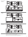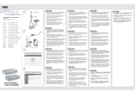
1
MIKROFON-LINE-MISCHER/ LINE-SPLITTER MICROPHONE LINE MIXER/LINE SPLITTER MIXEUR LIGNE MICRO/RÉPARTITEUR LIGNE MISCELATORE MICROFONO-LINE/LINE SPLITTER LMS-808 Best.-Nr. 20.2160 BEDIENUNGSANLEITUNG • INSTRUCTION MANUAL • MODE D’EMPLOI • ISTRUZIONI PER L’USO MANUAL DE INSTRUCCIONES • INSTRUKCJA OBSŁUGI • VEILIGHEIDSVOORSCHRIFTEN SIKKERHEDSOPLYSNINGER • SÄKERHETSFÖRESKRIFTER • TURVALLISUUDESTA D Bevor Sie einschalten … A Wir wünschen Ihnen viel Spaß mit Ihrem neuen Gerät von „img Stage Line“. Bitte lesen Sie diese Bedienungsanleitung vor dem Betrieb gründlich durch. Nur so lernen Sie alle Funktionsmöglichkeiten kennen, vermeiden Fehlbedienungen und schützen sich und Ihr Gerät vor eventuellen Schäden durch unsachgemäßen Gebrauch. Heben Sie die Anleitung für ein späteres Nachlesen auf. We wish you much pleasure with your new “img Stage Line” unit. Please read these operating instructions carefully prior to operating the unit. Thus, you will get to know all functions of the unit, operating errors will be prevented, and yourself and the unit will be protected against any damage caused by improper use. Please keep the operating instructions for later use. Der deutsche Text beginnt auf der Seite 4. The English text starts on page 4. CH GB Before switching on … F Avant toute installation … B Nous vous souhaitons beaucoup de plaisir à utiliser cet appareil “img Stage Line”. Lisez ce mode dʼemploi entièrement avant toute utilisation. Uniquement ainsi, vous pourrez apprendre lʼensemble des possibilités de fonctionnement de lʼappareil, éviter toute manipulation erronée et vous protéger, ainsi que lʼappareil, de dommages éventuels engendrés par une utilisation inadaptée. Conservez la notice pour pouvoir vous y reporter ultérieurement. Vi auguriamo buon divertimento con il vostro nuovo apparecchio di “img Stage Line”. Leggete attentamente le istruzioni prima di mettere in funzione lʼapparecchio. Solo così potete conoscere tutte le funzionalità, evitare comandi sbagliati e proteggere voi stessi e lʼapparecchio da eventuali danni in seguito ad un uso improprio. Conservate le istruzioni per poterle consultare anche in futuro. La version française se trouve page 8. Il testo italiano inizia a pagina 8. CH E Antes de la utilización … I PL Le deseamos una buena utilización para su nuevo aparato “img Stage Line”. Por favor, lea estas instrucciones de uso atentamente antes de hacer funcionar el aparato. De esta manera conocerá todas las funciones de la unidad, se prevendrán errores de operación, usted y el aparato estarán protegidos en contra de todo daño causado por un uso inadecuado. Por favor, guarde las instrucciones para una futura utilización. Prima di accendere … Przed uruchomieniem … Życzymy zadowolenia z nowego produktu “img Stage Line”. Dzięki tej instrukcji obsługi będą państwo w stanie poznać wszystkie funkcje tego urządzenia. Stosując się do instrukcji unikną państwo błędów i ewentualnego uszkodzenia urządzenia na skutek nieprawidłowego użytkowania. Prosimy zachować instrukcję. Tekst polski zaczyna się na stronie 12. La versión española comienza en la página 12. NL B S Voor u inschakelt … DK Før du tænder … Wij wensen u veel plezier met uw nieuwe apparaat van “img Stage Line”. Lees de veiligheidsvoorschriften grondig door, alvorens het apparaat in gebruik te nemen. Zo behoedt u zichzelf en het apparaat voor eventuele schade door ondeskundig gebruik. Bewaar de handleiding voor latere raadpleging. Tillykke med dit nye “img Stage Line” produkt. Læs sikkerhedsanvisningerne nøje før ibrugtagning, for at beskytte Dem og enheden mod skader, der skyldes forkert brug. Gem venligst denne betjeningsvejledning til senere brug. De veiligheidsvoorschriften vindt u op pagina 16. Sikkerhedsanvisningerne findes på side 16. Innan du slår på enheten … FIN Ennen kytkemistä … Vi önskar dig mycket glädje med din nya “img Stage Line” produkt. Läs igenom säkerhetsföreskrifterna innan enheten tas i bruk för att undvika skador till följd av felaktig hantering. Behåll instruktionerna för framtida bruk. Toivomme Sinulle paljon miellyttäviä hetkiä uuden “img Stage Line” laitteen kanssa. Ennen laitteen käyttöä pyydämme Sinua huolellisesti tutustumaan turvallisuusohjeisiin. Näin vältyt vahingoilta, joita virheellinen laitteen käyttö saattaa aiheuttaa. Ole hyvä ja säilytä käyttöohjeet myöhempää tarvetta varten. Säkerhetsföreskrifterna återfinns på sidan 16. Turvallisuusohjeet löytyvät sivulta 17. w w w.imgstageline.com 2 1 3 4 1 230V~/ 50Hz MAINS 11 3 R 2 5 1 STEREO OUT 12 3 L 2 6 2 7 1 8 3 OUT 2 2 CH 6 3 IN 1 1 3 OUT 2 2 CH5 CHCH 5 2 3 IN 1 9 1 3 2 2 OUT 13 CH 1 3 10 1 IN 14 2 3 R 1 2 STEREO IN 15 3 1 L 3 D A Bitte klappen Sie die Seite 3 heraus. Sie sehen dann immer die beschriebenen Bedienelemente und Anschlüsse. CH 1 Übersicht der Bedienelemente und Anschlüsse 7 1.1 Frontseite (Abb. 1) 1 LEDs für den Signalpegel grün = Eingangsignal vorhanden rot = Eingangsignal übersteuert 2 Betriebsanzeige 3 Regler LEVEL der Vorverstärkung für den linken und rechten Kanal 4 Umschalttaste, jeweils für die Mono-Kanäle 1–6, um den Regelbereich für die Level-Regler (5) an die jeweils angeschlossene Signalquelle anzupassen. Bei angeschlossener Line-Quelle die Taste ausrasten (Stellung „LINE“): Der Regelbereich beträgt -∞ bis +20 dB Bei angeschlossenem Mikrofon die Taste einrasten (Stellung „MIC“): Der Regelbereich beträgt -∞ bis +60 dB 5 Vorderer Drehknopf LEVEL, jeweils für die Kanäle CH1 bis CH6 Betriebsart SPLIT: Zum Einstellen des Kanalpegels der Ausgänge CH1 bis CH6 Betriebsart MIXER: Zum Einstellen des Anteils des jeweiligen Kanals am Gesamtsignal am Ausgang STEREO OUT (12); der hier eingestellte Signalpegel liegt gleichzeitig am jeweiligen Ausgang (13) des Kanals an. 6 Hinterer Drehknopf PAN, jeweils für die Kanäle CH1 bis CH6 Betriebsart SPLIT: Mit dem Regler wird das Verhältnis zwischen dem linken und rechten Kanal GB Please unfold page 3. Then you can always see the operating elements and connections described. 1 Operating Elements and Connections 1.1 Front panel (fig. 1) 1 LEDs for the signal level green = input signal is available red = input signal is overloaded 2 POWER LED 3 Controls LEVEL of the preamplification for the left channel and the right channel 4 Selector button, each for the mono channels 1 to 6, to adapt the control range for the level controls (5) to the signal source connected in each case. With a line source connected, disengage the button (position “LINE”): The control range is -∞ up to +20 dB With a microphone connected, engage the button (position “MIC”): The control range is -∞ up to +60 dB 5 Front rotary knob LEVEL, each for the channels CH 1 to CH 6 Operating mode SPLIT: To adjust the channel level of the outputs CH 1 to CH 6 Operating mode MIXER: To adjust the part of the respective channel of the total signal at the output STEREO OUT (12); the signal level adjusted at this output is at the same time present at the respective output (13) of the channel. 6 Rear rotary knob PAN, each for the channels CH 1 to CH 6 Operating mode SPLIT: With the control the ratio is adjusted between the left channel and the right channel of the stereo input signal in the respective output (13). Operating mode MIXER: Control for placing the mono input signal in the stereo base of the output signal 4 8 9 10 des Stereo-Eingangssignals im jeweiligen Ausgang (13) eingestellt. Betriebsart MIXER: Regler zum Platzieren des Mono-Eingangssignals in der Stereo-Basis des Ausgangssignals Umschalttaste MIX/SPLIT, jeweils für die MonoKanäle CH1 bis CH6, um die Betriebsart zu wählen: Taste ausgerastet: Betriebsart MIX Taste eingerastet: Betriebsart SPLIT Umschalttaste MIXER ON: Taste eingerastet: Der Mixer-Betrieb ist eingeschaltet. Arbeiten die jeweiligen Mono-Kanäle CH1 bis CH6 im Mixerbetrieb, so werden deren Kanalpegel auf den Masterkanal „STEREO OUT“ gegeben. Taste ausgerastet: Der Mixerbetrieb ist ausgeschaltet. Sind die jeweiligen Mono-Kanäle CH1 bis CH6 auf „MIX“ geschaltet, so arbeiten diese als separate Verstärker. Regler LEVEL STEREO OUT zum Einstellen des Pegels an den Ausgängen STEREO OUT (12) Ein-/Ausschalter POWER 1.2 Rückseite (Abb. 2) 11 Netzkabel zum Anschluss an eine Steckdose (230 V~/50 Hz) 12 Stereo-Ausgang (2 × XLR, symmetrisch) 13 Mono-Ausgang der Kanäle CH1 bis CH6 (XLR, symmetrisch) 14 Mono-Eingang der Kanäle CH1 bis CH6 (XLR, symmetrisch) 15 Stereo-Eingang (2 × XLR, symmetrisch) 2 WARNUNG Das Gerät wird mit lebensgefährlicher Netzspannung (230 V~) versorgt. Nehmen Sie deshalb niemals selbst Eingriffe am Gerät vor, die nicht in dieser Anleitung beschrieben sind. Durch unsachgemäßes Vorgehen besteht die Gefahr eines elektrischen Schlages. Beachten Sie auch unbedingt die folgenden Punkte: Das Gerät ist nur zur Verwendung im Innenbereich geeignet. Schützen Sie es vor Tropf- und Spritzwasser, hoher Luftfeuchtigkeit und Hitze (zulässiger Einsatztemperaturbereich 0–40 °C). G Stellen Sie keine mit Flüssigkeit gefüllten Gefäße, z. B. Trinkgläser, auf das Gerät. G Nehmen Sie das Gerät nicht in Betrieb bzw. ziehen Sie sofort den Netzstecker aus der Steckdose: 1. wenn sichtbare Schäden am Gerät oder am Netzkabel vorhanden sind, 2. wenn nach einem Sturz oder Ähnlichem der Verdacht auf einen Defekt besteht, 3. wenn Funktionsstörungen auftreten. Lassen Sie das Gerät in jedem Fall in einer Fachwerkstatt reparieren. G Ziehen Sie den Netzstecker nie am Kabel aus der Steckdose, fassen Sie immer am Stecker an. G Ein beschädigtes Netzkabel darf nur durch eine Fachwerkstatt ersetzt werden. G Verwenden Sie für die Reinigung nur ein trockenes, weiches Tuch, niemals Wasser oder Chemikalien. G Wird das Gerät zweckentfremdet, nicht richtig angeschlossen, falsch bedient oder nicht fachgerecht repariert, kann keine Haftung für daraus resultierende Sach- oder Personenschäden und keine Garantie für das Gerät übernommen werden. G Soll das Gerät endgültig aus dem Betrieb genommen werden, übergeben Sie es zur umweltgerechten Entsorgung einem örtlichen Recyclingbetrieb. Hinweise für den sicheren Gebrauch Das Gerät entspricht allen relevanten Richtlinien der EU und ist deshalb mit gekennzeichnet. 7 Selector button MIX/SPLIT, each for the mono channels CH 1 to CH 6 to select the operating mode: Button disengaged: operating mode MIX Button engaged: operating mode SPLIT 8 Selector button MIXER ON: Button engaged: The mixer mode is switched on. If the respective mono channels CH 1 to CH 6 operate in mixer mode, their channel levels are fed to the master channel “STEREO OUT”. Button disengaged: The mixer mode is switched off. If the respective mono channels CH 1 to CH 6 are switched to “MIX”, they operate as separate amplifiers. 9 Control LEVEL STEREO OUT for adjusting the level at the outputs STEREO OUT (12) 10 POWER switch 1.2 Rear panel (fig. 2) 11 Mains cable for connection to a mains socket (230 V~/50 Hz) 12 Stereo output (2 × XLR, balanced) 13 Mono output of the channels CH 1 to CH 6 (XLR, balanced) 14 Mono input of the channels CH 1 to CH 6 (XLR, balanced) 15 Stereo input (2 × XLR, balanced) 2 Safety Notes The unit corresponds to all relevant directives of the EU and is therefore marked with . WARNING The unit is supplied with hazardous mains voltage (230 V~). Leave servicing to skilled personnel only. Never make any modification on the unit not described in this instruction manual. Inexpert handling may cause an electric shock hazard. It is essential to observe the following items: The unit is suitable for indoor use only. Protect it against dripping water and splash water, high air humidity, and heat (admissible ambient temperature range 0 – 40 °C). G Do not place any vessels filled with liquid, e. g. drinking glasses, on the unit. G Do not set the unit into operation, and immediately disconnect the mains plug from the mains socket if 1. there is visible damage to the unit or to the mains cable, 2. a defect might have occurred after a drop or similar accident, 3. malfunctions occur. The unit must in any case be repaired by skilled personnel. G Never pull the mains cable to disconnect the mains plug from the mains socket, always seize the plug. G A damaged mains cable must be replaced by skilled personnel only. G For cleaning only use a dry, soft cloth, by no means chemicals or water. G No guarantee claims for the unit and no liability for any resulting personal damage or material damage will be accepted if the unit is used for other purposes than originally intended, if it is not correctly connected, operated, or not repaired in an expert way. G Important for U. K. Customers! The wires in this mains lead are coloured in accordance with the following code: blue = neutral brown = live As the colours of the wires in the mains lead of this appliance may not correspond with the coloured markings identifying the terminals in your plug, proceed as follows: 1. The wire which is coloured blue must be connected to the terminal in the plug which is marked with the letter N or coloured black. G 3 Einsatzmöglichkeiten Der Mikrofon-Line-Mischer / Line-Splitter ist aufgrund seines Konzepts für vielfältige Audio-Anwendungen einsetzbar. Im Splitter-Betrieb lässt sich ein StereoEingangssignal auf je sechs Mono-Ausgänge verteilen, wobei über Pan-Regler der Signalanteil des Stereo-Signals für jeden Kanal individuell einstellbar ist. Im Mixer-Betrieb können ein Stereo-Signal und maximal sechs Mono-Signale mit Mikrofon- oder Line-Pegel auf einen Stereo-Ausgang gemischt werden. Die sechs Mono-Kanäle sowie der StereoKanal können auch als separate Verstärker zur Pegel- oder Impedanzanpassung genutzt werden. 4 Aufstellmöglichkeiten Das Gerät ist für die Montage in ein Rack (482 mm / 19″) vorgesehen, kann aber auch als freistehendes Tischgerät verwendet werden. Für den Einbau in ein Rack wird 1 HE (Höheneinheit) = 44,45 mm benötigt. 5 Geräte anschließen Vor dem Neuanschluss oder dem Verändern bestehender Anschlüsse den Mikrofon-Line-Mischer / Line-Splitter und die anzuschließenden Geräte ausschalten. 1) Stereo-Gerät mit Line-Pegel (z. B. CD-Spieler, Mischpult usw.) an die XLR-Buchsen STEREO IN (15) anschließen. 2) An die Eingänge der Mono-Kanäle CH1 bis CH6 (14) können sowohl Mikrofone als auch MonoGeräte mit Line-Pegel angeschlossen werden. 3) Die Endverstärker für die Lautsprecher oder nachfolgende Geräte mit Line-Pegel können je nach Konfiguration an die XLR-Buchsen CH1 CH6 OUT (13) und STEREO OUT (12) angeschlossen werden. 2. The wire which is coloured brown must be connected to the terminal which is marked with the letter L or coloured red. If the unit is to be put out of operation definitively, take it to a local recycling plant for a disposal which is not harmful to the environment. 3 Applications Due to its concept, the microphone line mixer / line splitter can be used for versatile audio applications. In the splitter mode it is possible to distribute a stereo input signal to six mono outputs each, in which case the signal part of the stereo signal can be adjusted individually for each channel via pan controls. In the mixer mode a stereo signal and a maximum of six mono signals with microphone or line level can be mixed to a stereo output. The six mono channels as well as the stereo channel can also be used as separate amplifiers for level or impedance matching. 4 Setting Up The unit is provided for mounting into a rack (482 mm / 19″) but it can also be used as a table top unit. For the installation into a rack one rack space (height unit) = 44.45 mm is required. 5 Vorsicht! Ist die Phantomspeisung dazugeschaltet, dürfen keine asymmetrisch beschalteten Mikrofone oder Geräte mit Linepegel an den entsprechenden Eingang angeschlossen werden. Andernfalls können diese Mikrofone und Geräte beschädigt werden. D A CH 5.1 Mikrofon-Phantomspeisung dazuschalten Um auch phantomgespeiste Mikrofone betreiben zu können, lässt sich für jeden der sechs Mono-Kanäle getrennt eine 12-V-Phantomspeisung dazuschalten. Achtung! Zum Zuschalten der Phantomspeisung muss das Gerät geöffnet werden. Darum darf dies nur durch eine qualifizierte Fachkraft erfolgen. 1) Den Netzstecker aus der Steckdose ziehen. 2) Den Gehäusedeckel abschrauben. 3) Für die gewünschten Kanäle die entsprechenden Steckbrücken JP 101 (für Kanal CH 1) bis JP 601 (für Kanal CH 6) von „OFF“ nach „ON“ umstecken. 4) Den Gehäusedeckel wieder festschrauben. 5) Es wird empfohlen, die Eingangsbuchsen der mit Phantomspeisung beschalteten Kanäle entsprechenden zu kennzeichnen! 6 Bedienung 1) Vor dem Einschalten sollten alle Ausgangsregler (5 und 9) auf Minimum gestellt werden, um Einschaltgeräusche zu vermeiden. 2) Das Gerät mit dem Schalter POWER (10) einschalten. Zur Anzeige der Betriebsbereitschaft leuchtet die rote LED (2) über dem Schalter. Anschließend die angeschlossenen Geräte einschalten. 3) The power amplifiers for the speakers or subsequent units with line level can be connected to the XLR jacks CH 1 to CH 6 OUT (13) and STEREO OUT (12) depending on their configuration. GB Caution! If the phantom power is switched on, no unbalanced microphones or units with line level must be connected to the corresponding input. Otherwise, these microphones and units may be damaged. 5.1 Switching on the microphone phantom power To be able to operate also phantom-powered microphones, it is possible to switch on a 12 V phantom power separately for each of the six mono channels. Attention! To switch on the phantom power, the unit must be opened. Therefore, this must only be made by qualified expert personnel. 1) Disconnect the mains plug from the mains socket. 2) Unscrew the housing cover. 3) For the desired channels, rearrange the corresponding jumpers JP 101 (for channel CH 1) to JP 601 (for channel CH 6) from “OFF” to “ON”. 4) Tightly screw the housing cover again. 5) It is recommended to mark the input jacks of the channels provided with phantom power accordingly! Connecting the Units Prior to the new connection or change of existing connections switch off the microphone line mixer / line splitter and the units to be connected. 1) Connect a stereo unit with line level (e. g. CD player, mixer, etc.) to the XLR jacks STEREO IN (15). 2) It is possible to connect both microphones and mono units with line level to the inputs of the mono channels CH 1 to CH 6 (14). 6 Operation 1) Prior to switching on, all output controls (5 and 9) should be set to minimum to prevent switching noise. 2) Switch on the unit with the POWER switch (10). To indicate that the unit is ready for operation, the red LED (2) above the switch lights up. Then switch on the connected units. 5 D 6.1 Betriebsart Mixer (Abb. 4) A In der Betriebsart Mixer können ein Stereo-Kanal und bis zu sechs Mono-Kanäle auf einen StereoAusgangskanal gemischt werden. CH 1) Die Umschalttaste MIX/SPLIT (7) für den jeweiligen Kanal einrasten sowie die Umschalttaste MIXER ON (8) einrasten. 2) Den Regler LEVEL STEREO OUT (9) so weit aufdrehen, dass das Mischungsverhältnis der angeschlossenen Tonquellen optimal eingestellt werden kann. 3) Mit den Umschalttasten LINE/MIC (4) die MonoKanäle CH1–CH6 auf die angeschlossenen Quellen einstellen. Bei angeschlossenem Mikrofon die Umschalttaste einrasten und bei Geräten mit Line-Pegel ausrasten. 4) Mit den Reglern LEVEL STEREO IN (3) und den Kanalreglern LEVEL CH1–CH6 (5) das gewünschte Lautstärkeverhältnis einstellen: Die Tonquellen, die am lautesten zu hören sein sollen, so aussteuern, dass die entsprechende LED (1) bei der lautesten Musikpassage kurz rot leuchtet. 5) Mit den Reglern PAN (6) der Mono-Kanäle CH1– CH6 das Mono-Kanalsignal wie gewünscht in der Stereo-Basis platzieren. 6) Mit dem Regler LEVEL STEREO OUT (9) den endgültigen Pegel des Stereo-Mastersignals einstellen. 6.2 Betriebsart Splitter (Abb. 5) Im Betriebsmodus Splitter lässt sich ein Stereo-Signal auf sechs Mono-Kanäle und einen Stereo-Kanal verteilen. Bei den Mono-Kanälen lassen sich die Signalanteile des Stereo-Signals mit den PAN-Reglern individuell einstellen. Bei dem Stereo-Ausgangskanal ist keine freie Zuordnung möglich, das linke Eingangssignal ist dem linken Ausgangssignal zugeordnet und das rechte Eingangssignal ist dem rechten Ausgangssignal zugeordnet. GB 6.1 Mixer mode (fig. 4) In the mixer mode a stereo channel and up to six mono channels can be mixed to a stereo output channel. 1) Engage the selector button MIX/SPLIT (7) for the respective channel and engage the selector button MIXER ON (8). 2) Turn up the control LEVEL STEREO OUT (9) so that the mixing ratio of the connected audio sources can be adjusted in an optimum way. 3) With the selector buttons LINE/MIC (4) adjust the mono channels CH 1 to CH 6 to the connected sources. In case of a microphone connected engage the selector button, and in case of units with line level disengage it. 4) With the controls LEVEL STEREO IN (3) and the channel controls LEVEL CH 1 to CH 6 (5) adjust the desired volume ratio: Control the levels of the audio sources to be heard at highest volume so that the corresponding LED (1) shortly lights up with the music passage of the highest volume. 5) With the controls PAN (6) of the mono channels CH 1 to CH 6 place the mono channel signal in the stereo base as desired. 6) With the control LEVEL STEREO OUT (9) adjust the definitive level of the stereo master signal. 6.2 Splitter mode (fig. 5) In the splitter mode a stereo signal can be distributed to six mono channels and a stereo channel. For the mono channels, the signal parts of the stereo signal can individually be adjusted with the PAN controls. For the stereo output channel, no free assignment is possible, the left input signal is assigned to the left output signal, and the right input signal is assigned to the right output signal. 1) Disengage the selector button MIX/SPLIT (7) for the respective channel. 2) With the controls INPUT LEVEL (3) adjust the input level of the stereo signal so that the LEDs 6 1) Die Umschalttaste MIX/SPLIT (7) für den jeweiligen Kanal ausrasten. 2) Mit den Reglern INPUT LEVEL (3) den Eingangspegel des Stereo-Signals so einstellen, dass die LEDs (1) bei der lautesten Musikpassage kurz rot leuchten. 3) Für die sechs Mono-Kanäle mit den PAN-Reglern (6) den gewünschten Signalanteil des Stereo-Signals einstellen. 4) Mit den Reglern LEVEL CH1–CH6 (5) die Pegel der Mono-Kanäle individuell einstellen. 5) Mit den Reglern LEVEL STEREO OUT (9) den Pegel des Stereo-Ausgangssignals einstellen. 6.4 Kombinierte Betriebsarten Werden in der Betriebsart Splitter nicht alle sechs Mono-Kanäle als Ausgänge benötigt, können die übrigen Kanäle als einzelne unabhängige Verstärker betrieben werden. Siehe Kapitel 6.3. 7 STEREO IN: . . . . . . . . . . 250 mV, 30 kΩ XLR, symmetrisch CH1–CH6: . . . . . . . . . . . Line 100 mV, 40 kΩ umschaltbar auf Mic 1 mV, 6,6 kΩ XLR, symmetrisch Phantomspeisung: . . . . . 12 V (intern schaltbar) 6.3 Betriebsart 8-Kanal-Verstärker (Abb. 6) In dieser Betriebsart arbeiten die Kanäle als unabhängige Verstärker, die ein niederohmiges, symmetrisches Ausgangssignal liefern. Die sechs MonoKanäle und der Stereo-Kanal können einzeln im Pegel angepasst werden. Die Pegelanpassung ist z. B. notwendig, wenn eine Signalquelle einen zu geringen Ausgangspegel hat, um ein nachfolgendes Gerät auszusteuern. In dieser Betriebsart kann das Gerät auch als 6fach-Mikrofonvorverstärker genutzt werden. 1) Die Umschalttaste MIX/SPLIT (7) für den jeweiligen Kanal einrasten sowie die Umschalttaste MIXER ON (8) ausrasten. 2) Mit den Umschalttasten LINE/MIC (4) die MonoKanäle CH1–CH6 auf die angeschlossenen Quellen einstellen. Bei angeschlossenem Mikrofon die Umschalttaste einrasten und bei Geräten mit Line-Pegel ausrasten. 3) Bei den Mono-Kanälen mit den Reglern LEVEL CH1– CH6 (5) den gewünschten Pegel einstellen. 4) Bei dem Stereo-Kanal den Regler LEVEL STEREO OUT (9) auf Maximum stellen. 5) Mit den Reglern LEVEL STEREO IN (3) für den linken und rechten Kanal den gewünschten Pegel individuell einstellen. (1) shortly light up with the music passage of the highest volume. 3) For the six mono channels adjust the desired signal part of the stereo signal with the PAN controls (6). 4) With the controls LEVEL CH 1 to CH 6 (5) adjust the levels of the mono channels individually. 5) With the controls LEVEL STEREO OUT (9) adjust the level of the stereo output signal. 6.3 8-channel amplifier mode (fig. 6) In this mode the channels operate as independent amplifiers which supply a balanced output signal of low impedance. The levels of the six mono channels and the stereo channel can individually be matched. The level matching is e.g. necessary if the output level of a signal source is too low to control a subsequent unit. In this mode the unit can also be used as 6-fold microphone preamplifier. 1) Engage the selector button MIX/SPLIT (7) for the respective channel and disengage the selector button MIXER ON (8). 2) With the selector buttons LINE/MIC (4) adjust the mono channels CH1 to CH6 to the connected sources. In case of a microphone connected engage the selector button, and in case of units with line level disengage it. 3) For the mono channels adjust the desired level with the controls LEVEL CH1 to CH6 (5). 4) For the stereo channel set the control LEVEL STEREO OUT (9) to maximum. 5) With the controls LEVEL STEREO IN (3) adjust the desired level individually for the left channel and the right channel. Technische Daten Eingänge (Eingangsempfindlichkeit bei 1 V Ausgangspegel, Eingangsimpedanz) Ausgänge (Nennpegel, Ausgangsimpedanz) STEREO OUT: . . . . . . . . 1 V, 200 Ω XLR, symmetrisch CH1–CH6: . . . . . . . . . . . 1 V, 200 Ω XLR, symmetrisch Frequenzbereich: . . . . . . . . 10 Hz – 30 000 Hz (+0/-0,5 dB) Klirrfaktor: . . . . . . . . . . . . . . 0,02 % Störabstand: . . . . . . . . . . . . 81 dB, bewertet Übersprechen: . . . . . . . . . . -63 dB (1 kHz) Stromversorgung: . . . . . . . . 230 V~/50 Hz/10 VA Einsatztemperatur: . . . . . . . 0 – 40 °C Abmessungen (B × H × T): . 482 × 48 × 205 mm, 1 Höheneinheit Gewicht: . . . . . . . . . . . . . . . 2,9 kg Änderungen vorbehalten. 7 Specifications Inputs (Input sensitivity at 1 V output level, input impedance) STEREO IN: . . . . . . . . . . 250 mV, 30 kΩ XLR, balanced CH 1 to CH 6: . . . . . . . . . Line 100 mV, 40 kΩ switchable to Mic 1 mV, 6.6 kΩ XLR, balanced Phantom power: . . . . . . . 12 V (can be switched internally) Outputs (rated level, output impedance) STEREO OUT: . . . . . . . . 1 V, 200 Ω XLR, balanced CH 1 to CH 6: . . . . . . . . . 1 V, 200 Ω XLR, balanced Frequency range: . . . . . . . . 10 Hz – 30 000 Hz (+0/-0.5 dB) THD: . . . . . . . . . . . . . . . . . . 0.02 % S/N ratio: . . . . . . . . . . . . . . 81 dB/weighted Crosstalk: . . . . . . . . . . . . . . -63 dB (1 kHz) Power supply: . . . . . . . . . . . 230 V~/50 Hz/10 VA Ambient temperature: . . . . . 0 – 40 °C Dimensions (W × H × D): . . 482 × 48 × 205 mm, 1 rack space Weight: . . . . . . . . . . . . . . . . 2.9 kg 6.4 Combined operating modes If not all six mono channels are required as outputs in the splitter mode, the remaining channels can be operated as individual and independent amplifiers. See chapter 6.3. Subject to technical modification. Betriebsart Mixer Mixer Mode Betriebsart Splitter Splitter Mode 8-Kanal-Verstärker 8-Channel Amplifier Diese Bedienungsanleitung ist urheberrechtlich für MONACOR ® INTERNATIONAL GmbH & Co. KG geschützt. Eine Reproduktion für eigene kommerzielle Zwecke – auch auszugsweise – ist untersagt. All rights reserved by MONACOR ® INTERNATIONAL GmbH & Co. KG. No part of this instruction manual may be reproduced in any form or by any means for any commercial use. 7 F B Ouvrez le présent livret page 3 de manière à visualiser les éléments et branchements. 7 Touche de commutation MIX/SPLIT, respectivement pour les canaux mono CH1 à CH6, pour sélectionner le mode de fonctionnement : CH 1 Eléments et branchements touche désenclenchée : mode de fonctionnement MIX 1.1 Face avant (schéma 1) touche enclenchée : mode de fonctionnement SPLIT 1 LEDs pour le niveau de signal verte : signal dʼentrée disponible rouge : signal dʼentrée en surcharge 2 Témoin de fonctionnement 3 Potentiomètres de réglage LEVEL pour la préamplification pour le canal gauche et le canal droit 4 Touche de commutation, respectivement pour les canaux mono 1–6, pour adapter la plage de réglage pour les réglages de niveau (5) à la source de signal reliée dans chaque cas : source reliée Ligne : désenclenchez la touche (position “LINE”) : la plage de réglage va de -∞ à +20 dB micro relié : enclenchez la touche (position “MIC”) : la plage de réglage va de -∞ à +60 dB 5 Potentiomètre de réglage avant LEVEL respectivement pour les canaux CH1 à CH6 mode de fonctionnement SPLIT : pour régler le niveau du canal des sorties CH1 à CH6 mode de fonctionnement MIXER : pour régler la part du canal correspondant sur le signal total à la sortie STEREO OUT (12) ; le niveau de signal réglé ici est simultanément présent à la sortie correspondante (13) du canal 6 Potentiomètre de réglage arrière PAN, respectivement pour les canaux CH1 à CH6 mode de fonctionnement SPLIT : pour régler le rapport entre le canal gauche et le canal droit du signal dʼentrée stéréo à la sortie correspondante (13). mode de fonctionnement MIXER : réglage pour placer le signal dʼentrée mono dans la base stéréo du signal de sortie I Vi preghiamo di aprire completamente la pagina 3. Così vedrete sempre gli elementi di comando e i collegamenti descritti. 1 Elementi di comando e collegamenti 1.1 Pannello frontale (fig. 1) 1 LED per il livello dei segnali verde = segnale dʼingresso presente rosso = segnale dʼingresso sovrapilotato 2 Spia di funzionamento 3 Regolatori LEVEL della preamplificazione per i canali di destra e di sinistra 4 Commutatore per i canali 1 – 6, per adattare il campo di regolazione dei regolatori Level (5) alla sorgente collegata. Se è collegata una sorgente Line, sbloccare il tasto (posizione “LINE”): Il campo di regolazione è fra -∞ e +20 dB Se è collegato un microfono, premere fino allo scatto il tasto (posizione “MIC”): Il campo di regolazione è fra -∞ e +60 dB 5 Manopola anteriore LEVEL, per i canali CH 1 a CH 6 Modalità SPLIT: per impostare il livello dei canali delle uscite CH 1 a CH 6 Modalità MIXER: per impostare la parte che il relativo canale occupa nel segnale globale presente allʼuscita STEREO OUT (12); il livello impostato qui è quello presente nello stesso tempo alla relativa uscita (13) del canale. 6 Manopola posteriore PAN, per i canali CH 1 a CH 6 Modalità SPLIT: con il regolatore si imposta nella relativa uscita (13) il rapporto fra il canale destro e quello sinistro del segnale stereo dʼingresso. Modalità MIXER: regolatore per posizionare il segnale mono nella base stereo del segnale dʼuscita 8 8 Touche de commutation MIXER ON : touche enclenchée : le fonctionnement Mixeur est activé. Si les canaux mono respectifs CH1 à CH6 fonctionnent en mode Mixeur, leur niveau de canal est appliqué sur le canal master “STEREO OUT”. AVERTISSEMENT Lʼappareil est alimenté par une tension dangereuse en 230 V~. Ne faites jamais de modification si cela nʼest pas décrit dans la présente notice. Faites toujours appel à un technicien spécialisé pour effectuer les réparations. Une mauvaise manipulation pourrait générer une décharge électrique. Respectez scrupuleusement les points suivants : G Lʼappareil nʼest conçu que pour une utilisation en intérieur. Protégez-le des éclaboussures, de tout type de projections dʼeau, dʼune humidité élevée et de la chaleur (température ambiante admissible 0–40 °C). G En aucun cas, vous ne devez poser dʼobjet contenant du liquide ou un verre sur lʼappareil. G Ne faites pas fonctionner lʼappareil et débranchez le cordon secteur immédiatement dans les cas suivants : 1. lʼappareil ou le cordon secteur présentent des dommages visibles. 2. après une chute ou accident similaire, vous avez un doute sur lʼétat de lʼappareil. 3. des dysfonctionnements apparaissent. Dans tous les cas, les dommages doivent être réparés par un technicien spécialisé. G Ne débranchez jamais lʼappareil en tirant sur le cordon secteur ; retirez toujours le cordon secteur en tirant la fiche. 14 Entrée mono des canaux CH1 à CH6 (XLR, symétrique) G Tout cordon secteur endommagé doit être remplacé impérativement par un technicien spécialisé. 15 Entrée stéréo (2 × XLR, symétrique) G Pour le nettoyage, utilisez un chiffon sec et doux, en aucun cas de produits chimiques ou dʼeau. G Nous déclinons toute responsabilité en cas de dommages corporels ou matériels résultants si lʼappareil est utilisé dans un but autre que celui pour lequel il a été conçu, sʼil nʼest pas correctement branché, utilisé ou réparé par une personne habilitée ; en outre, la garantie deviendrait caduque. touche désenclenchée : le fonctionnement Mixeur est désactivé. Si les canaux mono respectifs CH1 à CH6 sont commutés sur “MIX”, ils fonctionnent comme amplificateurs distincts. 9 Potentiomètre de réglage LEVEL STEREO OUT pour régler le niveau aux sorties STEREO OUT (12) 10 Interrupteur POWER Marche/Arrêt 1.2 Face arrière (schéma 2) 11 Cordon secteur à relier à une prise secteur 230 V~/50 Hz 12 Sortie stéréo (2 × XLR, symétrique) 13 Sortie mono des canaux CH1 à CH6 (XLR, symétrique) 2 Conseils de sécurité et dʼutilisation Cet appareil répond à toutes les directives nécessaires de lʼUnion européenne et porte donc le symbole . 7 Selettore MIX/SPLIT, per i canali mono CH 1 a CH 6, per scegliere la modalità di funzionamento: tasto sbloccato: modalità MIX tasto premuto fino allo scatto: modalità SPLIT 8 Selettore MIXER ON: Tasto premuto fino allo scatto: è attivato il funzionamento mixer. Se i relativi canali mono CH 1 a CH 6 funzionano come mixer, i loro livelli vengono portati sul canale master “STEREO OUT”. Tasto sbloccato: il funzionamento a mixer è disattivato. Se i relativi canali mono CH 1 a CH 6 sono messi su “MIX”, funzionano come amplificatori separati. 9 Regolatore LEVEL STEREO OUT per impostare il livello alle uscite STEREO OUT (12) 10 Interruttore on/off POWER 1.2 Pannello posteriore (fig. 2) 11 Cavo rete per il collegamento con la rete (230 V~/50 Hz) 12 Uscita stereo (2 × XLR, simmetrica) 13 Uscita mono dei canali CH 1 a CH 6 (XLR, simmetrica) 14 Ingresso mono dei canali CH 1 a CH 6 (XLR, simmetrico) 15 Ingresso stereo (2 × XLR, simmetrico) 2 Avvertenze di sicurezza Lʼapparecchio è conforme a tutte le direttive rilevanti dellʼUE e pertanto porta la sigla . AVVERTIMENTO Questʼapparecchio funziona con pericolosa tensione di rete di 230 V~. Non eseguire mai interventi al suo interno al di fuori di quelli descritti nelle presenti istruzioni. La manipolazione scorretta può provocare delle scariche pericolose. Durante lʼuso si devono osservare assolutamente anche i seguenti punti: G Far funzionare lʼapparecchio solo allʼinterno di locali. Proteggerlo dallʼacqua gocciolante e dagli spruzzi dʼacqua, da alta umidità dellʼaria e dal calore (temperatura dʼimpiego ammessa fra 0 °C e 40 °C). G Non depositare sullʼapparecchio dei contenitori riempiti di liquidi, p. es. bicchieri. G Non mettere in funzione lʼapparecchio e staccare subito la spina rete se: 1. lʼapparecchio o il cavo rete presentano dei danni visibili; 2. dopo una caduta o dopo eventi simili sussiste il sospetto di un difetto; 3. lʼapparecchio non funziona correttamente. Per la riparazione rivolgersi sempre ad unʼofficina competente. G Staccare il cavo rete afferrando la spina, senza tirare il cavo. G Il cavo rete, se danneggiato, deve essere sostituito solo da un laboratorio specializzato. G Per la pulizia usare solo un panno morbido, asciutto; non impiegare in nessun caso prodotti chimici o acqua. G Nel caso dʼuso improprio, di collegamenti sbagliati, dʼimpiego scorretto o di riparazione non a regola dʼarte dellʼapparecchio, non si assume nessuna responsabilità per eventuali danni consequenziali a persone o a cose e non si assume nessuna garanzia per lʼapparecchio. Se si desidera eliminare lʼapparecchio definitivamente, consegnarlo per lo smaltimento ad unʼistituzione locale per il riciclaggio. Lorsque lʼappareil est définitivement retiré du service, vous devez le déposer dans une usine de recyclage de proximité pour contribuer à son élimination non polluante. 3 Possibilités dʼutilisation Le mixeur Ligne micro / répartiteur Ligne est utilisable pour de multiples applications audio grâce à son concept. En mode Répartiteur, un signal dʼentrée stéréo peut être réparti sur respectivement six sorties mono où la part de signal du signal stéréo est réglable individuellement pour chaque canal via des réglages de panoramique. En mode Mixeur, un signal stéréo et au plus six signaux mono avec niveau micro ou niveau ligne peuvent être mixés sur une sortie stéréo. Les six canaux mono et le canal stéréo peuvent être utilisés également comme amplificateurs distincts pour une adaptation de niveau ou dʼimpédance. 3) Les amplificateurs pour les haut-parleurs ou les appareils suivants avec niveau ligne peuvent être reliés selon leur configuration, aux prises XLR CH1–CH6 OUT (13) et STEREO OUT (12). F B CH Attention ! Si lʼalimentation fantôme est allumée, aucun microphone asymétrique ou appareil à niveau ligne ne doit être relié à lʼentrée correspondante. Ces microphones ou appareils peuvent être endommagés. 5.1 Activation de lʼalimentation fantôme Pour pouvoir faire fonctionner également des microphones à alimentation fantôme, une alimentation fantôme 12 V peut être activée séparément pour chacun des six canaux mono. Attention ! Pour allumer lʼalimentation fantôme, lʼappareil doit être ouvert. Seul un personnel qualifié est autorisé à le faire. 1) Retirez la prise secteur du secteur. 2) Dévissez le couvercle du boîtier. 4 Possibilités de positionnement Lʼappareil est prévu pour un montage dans un rack (482 mm / 19″), il peut également être posé sur une table. Pour le montage dans un rack, une unité (1 U = 44,45 mm) est nécessaire. 5 1) Reliez un appareil stéréo avec niveau ligne (par exemple lecteur CD, table de mixage…) aux prises XLR STEREO IN (15). 2) Il est possible de relier aux entrées des canaux mono CH1 à CH6 (14) aussi bien des micros que des appareils mono avec niveau ligne. Possibilità dʼimpiego Grazie alla sua concezione, il miscelatore microfono-line / line splitter trova impiego in molteplici applicazioni audio. Nel funzionamento splitter, un segnale stereo dʼingresso può essere suddiviso fra sei uscite mono, mentre la parte del segnale stereo può essere regolata in modo individuale per ogni canale per mezzo del regolatore panoramico. Nel funzionamento mixer, un segnale stereo e un massimo di sei segnali mono con livello microfono o Line possono essere miscelati su unʼuscita stereo. I sei canali mono e il canale stereo possono essere sfruttati anche come amplificatori separati per lʼadattamento del livello o dellʼimpedenza. 4 Possibilità di collocamento Lʼapparecchio è previsto per il montaggio in un rack (482 mm / 19″), ma può essere collocato anche liberamente su un tavolo. Per il montaggio in un rack è richiesta unʼunità di altezza RS (= 44,45 mm). 5 4) Revissez le couvercle du boîtier. 5) Il est recommandé de repérer les prises dʼentrée des canaux fournis avec lʼalimentation fantôme en fonction ! Branchements Avant tout nouveau branchement ou toute modification des branchements existants, éteignez le mixeur Ligne micro/ Répartiteur ligne et les appareils à relier. 3 3) Pour les canaux souhaités, repositionnez les cavaliers correspondants JP 101 (pour canal CH1) à JP 601 (pour canal CH6) de “OFF” vers “ON”. Collegamento degli apparecchi Prima di eseguire un nuovo collegamento o di modificare collegamenti esistenti occorre spegnere il miscelatore / splitter nonché gli apparecchi da collegare. 1) Collegare un apparecchio stereo con livello Line (p. es. un lettore CD, mixer ecc.) con le prese XLR STEREO IN (15). 2) Agli ingressi dei canali mono CH 1 a CH 6 (14) si possono collegare sia microfoni che apparecchi mono con livello Line. 3) Gli amplificatori finali per gli altoparlanti o per apparecchi a valle possono essere collegati, a seconda della configurazione, con le prese XLR CH 1 – CH 6 OUT (13) e STEREO OUT (12). 6 Utilisation 1) Avant dʼallumer, les potentiomètres de réglage (5 et 9) devraient être mis sur le minimum pour éviter tout bruit fort à lʼallumage. 2) Allumez lʼappareil avec lʼinterrupteur POWER (10). La LED rouge (2) au-dessus de lʼinterrupteur brille comme témoin de fonctionnement. Ensuite allumez les appareils reliés. Attenzione! Se è inserita lʼalimentazione phantom, al relativo ingresso non si devono collegare microfoni asimmetrici o apparecchi con livello Line per non danneggiare detti microfoni e apparecchi. I 5.1 Aggiungere lʼalimentazione phantom per il microfono Per poter usare anche microfoni con alimentazione phantom, per ognuno dei sei canali mono è possibile aggiungere separatamente unʼalimentazione phantom a 12 V. Attenzione! Per aggiungere lʼalimentazione phantom occorre aprire lʼapparecchio. Perciò questa operazione deve essere fatta solo da un persona esperta e qualificata. 1) Staccare la spina dalla presa di rete. 2) Svitare il coperchio del contenitore. 3) Per i canali desiderati, spostare i relativi ponticelli JP 101 (per canale CH 1) a JP 601 (per canale CH 6) da “OFF” a “ON”. 4) Avvitare di nuovo il coperchio. 5) Si consiglia di marcare le prese dʼingresso dei canali con alimentazione phantom! 6 Funzionamento 1) Prima dellʼaccensione, tutti i regolatori delle uscite (5 e 9) dovrebbero essere portati sul minimo per escludere rumori di commutazione. 2) Accendere lʼapparecchio con lʼinterruttore POWER (10). Si accende il LED rosso (2) sopra lʼinterruttore come spia di funzionamento. Quindi accendere gli apparecchi collegati. 9 F B CH 6.1 Mode de fonctionnement Mixeur (schéma 4) 1) Désenclenchez la touche de commutation MIX/ SPLIT (7) pour le canal correspondant. Avec ce mode de fonctionnement, un canal stéréo et six canaux mono au plus peuvent être mixés sur un canal de sortie stéréo. 2) Avec les réglages INPUT LEVEL (3), réglez le niveau dʼentrée du signal stéréo de telle sorte que les LEDs (1) brillent brièvement en rouge pour les passages de musique les plus forts. 1) Enclenchez la touche de commutation MIX/ SPLIT (7) pour le canal correspondant et enclenchez la touche de commutation MIXER ON (8). 2) Tournez le réglage LEVEL STEREO OUT (9) jusquʼà ce que le rapport de mixage des sources reliées soit réglé de manière optimale. 3) Avec les touches de commutation LINE/MIC (4), réglez les canaux mono CH1–CH6 sur les sources reliées. Si un microphone est connecté, enclenchez la touche de commutation et désenclenchez-la pour des appareils avec niveau ligne. 4) Avec les potentiomètres de réglage LEVEL STEREO IN (3) et les réglages de canaux CH1–CH6 (5), réglez le rapport de volume souhaité : réglez les sources audio qui doivent être le plus fort de sorte que la LED correspondante (1) brille brièvement en rouge pour un passage de musique avec le volume le plus élevé. 5) Placez le signal de canal mono comme souhaité dans la base stéréo avec les réglages PAN (6) des canaux mono CH1–CH6. 6) Avec le réglage LEVEL STEREO OUT (9), réglez le niveau définitif du signal master stéréo. 6.2 Mode de fonctionnement Répartiteur (schéma 5) Avec le mode de fonctionnement Répartiteur, un signal stéréo peut être réparti sur six canaux mono et un canal stéréo. Dans le cas de canaux mono, les parts de signal du signal stéréo peuvent être réglées séparément avec les réglages PAN. Pour un canal de sortie stéréo, aucune attribution libre nʼest possible, le signal dʼentrée gauche est attribué au signal de sortie gauche et le signal dʼentrée droit est attribué au signal de sortie droit. I Entrées (Sensibilité dʼentrée pour niveau de sortie 1 V, impédance dʼentrée) 5) Avec les réglages LEVEL STEREO OUT (9), réglez le niveau du signal de sortie stéréo. Sorties (Niveau nominal, impédance de sortie) 1) Enclenchez la touche de commutation MIX/SPLIT (7) pour le canal correspondant et desenclenchez la touche de commutation MIXER ON (8). Bande passante : . . . . . . . . 10 Hz–30 000 Hz, (+0/-0,5 dB) 2) Avec les touches de commutation LINE/MIC (4), réglez les canaux mono CH1–CH6 sur les sources reliées. Si un microphone est relié, enclenchez la touche de commutation et pour des appareils à niveau ligne, désenclenchez-la. 3) Pour des canaux mono, réglez le volume souhaité avec les réglages LEVEL CH1–CH6 (5). 4) Pour un canal stéréo, réglez le réglage LEVEL STEREO OUT (9) sur le maximum. 5) Avec les réglages LEVEL STEREO IN (3), réglez individuellement le niveau souhaité pour le canal droit et le canal gauche. 2) Aprire il regolatore LEVEL STEREO OUT (9) al punto tale che si possa impostare in modo ottimale il rapporto di miscelazione fra le sorgenti collegate. 4) Con i regolatori LEVEL CH 1 – CH 6 (5) impostare il livello per ogni canale mono. 6) Con il regolatore LEVEL STEREO OUT (9) impostare il livello definitivo del segnale stereo master. 6.2 Modalità splitter (fig. 5) Nella modalità splitter, un segnale stereo può essere distribuito fra sei canali mono e un canale stereo. Per i canali mono, le parti del segnale stereo possono essere impostate individualmente con lʼaiuto del regolatore panoramico. Nel canale stereo dʼuscita non è possibile unʼassegnazione libera: il segnale di sinistra è assegnato al canale sinistro dʼuscita e il segnale destro dʼingresso al segnale destro dʼuscita. 1) Sbloccare il selettore MIX/SPLIT (7) per il relativo canale. CH1–CH6 : . . . . . . . . . . Ligne 100 mV, 40 kΩ commutable sur Mic 1 mV, 6,6 kΩ XLR, symétrique Avec ce mode de fonctionnement, les canaux fonctionnent comme amplificateurs indépendants délivrant un signal de sortie symétrique basse impédance. Les niveaux des six canaux mono et du canal stéréo peuvent être adaptés séparément. Lʼadaptation de niveau est par exemple nécessaire si le niveau de sortie dʼune source de signal est trop faible pour contrôler un appareil placé après. Avec ce mode de fonctionnement, lʼappareil peut également être utilisé comme préamplificateur micro 6 voies. 3) Per i sei canali mono impostare la parte desiderata del segnale stereo servendosi dei regolatori PAN (6). 5) Con i regolatori PAN (6) dei canali mono CH 1 – CH 6 posizionare il segnale mono nella base stereo secondo il proprio gusto. Caractéristiques techniques STEREO IN : . . . . . . . . . 250 mV, 30 kΩ, XLR, symétrique 6.3 Mode de fonctionnement amplificateur 8 canaux (schéma 6) 1) Premere fino allo scatto il selettore MIX/SPLIT (7) per il relativo canale nonché il selettore MIXER ON (8). 4) Con i regolatori LEVEL STEREO IN (3) e con sei quelli dei canali LEVEL CH 1 – CH 6 (5) impostare il suono desiderato: regolare le sorgenti che devono essere le più forti in modo tale che il relativo LED (1) si accende brevemente di color rosso nei passaggi musicali più forti. 10 7 4) Avec les réglages LEVEL CH1–CH6 (5), réglez individuellement les niveaux des canaux mono. 2) Con i regolatori INPUT LEVEL (3) impostare il livello dʼingresso del segnale stereo in modo tale che i LED (1) si accendono brevemente di rosso nei brani musicali più forti. 3) Con i commutatori LINE/MIC (4) adattare i canali mono CH 1 – CH 6 alle sorgenti collegate. Se è collegato un microfono, premere il tasto fino allo scatto; nel caso di apparecchi con livello Line sbloccare il tasto. Si en mode répartiteur, les six canaux mono ne sont pas utilisés comme sorties, les canaux restants peuvent fonctionner comme amplificateurs distincts indépendants. Voir chapitre 6.3. 3) Pour les six canaux mono, réglez la part voulue du signal stéréo avec les réglages PAN (6). Nella modalità mixer, un canale stereo e fino a sei canali mono possono essere miscelati su un canale stereo dʼuscita. 6.1 Modalità mixer (fig. 4) 6.4 Modes de fonctionnement combinés 5) Con i regolatori LEVEL STEREO OUT (9) impostare il livello del segnale stereo dʼuscita. 6.3 Modalità amplificatore a 8 canali (fig. 6) In questo modalità, i canali funzionano come amplificatori indipendenti che forniscono un segnale dʼuscita simmetrico, a bassa impedenza. I livelli dei canali mono e del canale stereo possono essere adattati singolarmente. Lʼadattamento del livello è necessario, p. es., se una sorgente presenta un livello dʼuscita troppo basso per poter pilotare un apparecchio a valle. In questa modalità, lʼapparecchio può essere impiegato anche come preamplificatore 6 × per microfono. 1) Premere fino allo scatto il selettore MIX/SPLIT (7) per il relativo canale e sbloccare il selettore MIXER ON (8). 2) Con i commutatori LINE/MIC (4) adattare i canali mono CH 1 – CH 6 alle sorgenti collegate. Se è collegato un microfono, premere il tasto fino allo scatto; nel caso di apparecchi con livello Line sbloccare il tasto. Alimentation fantôme : . . 12 V (commutable en interne) STEREO OUT : . . . . . . . 1 V, 200 Ω XLR, symétrique CH1–CH6 : . . . . . . . . . . 1 V, 200 Ω XLR, symétrique Taux de distorsion : . . . . . . 0,02 % Rapport signal/bruit : . . . . . 81 dB, pondéré Diaphonie : . . . . . . . . . . . . . -63 dB (1 kHz) Alimentation : . . . . . . . . . . . 230 V~/50 Hz/10 VA Température fonc. : . . . . . . 0–40 °C Dimensions (L × H × P) : . . . 482 × 48 × 205 mm, 1 unité Poids : . . . . . . . . . . . . . . . . 2,9 kg Tout droit de modification réservé. 6.4 Modalità combinate Se nella modalità splitter non si usano tutti e sei i canali come uscite, gli altri canali possono funzionare come amplificatori singoli, indipendenti. Vedi cap. 6.3. 7 Dati tecnici Ingressi (sensibilità allʼingresso con 1 V di livello dʼuscita, impedenza allʼingresso ) STEREO IN: . . . . . . . . . . 250 mV, 30 kΩ XLR, simmetrico CH 1 – CH 6: . . . . . . . . . . Line 100 mV, 40 kΩ commutabile a Mic 1 mV, 6,6 kΩ XLR, simmetrico Alimentazione phantom: . 12 V (commutabile internamente) Uscite (livello nominale, impedenza allʼuscita) STEREO OUT: . . . . . . . . 1 V, 200 Ω XLR, simmetrica CH 1 – CH 6: . . . . . . . . . . 1 V, 200 Ω XLR, simmetrica Gamma di frequenze: . . . . . 10 Hz – 30 000 Hz (+0/-0,5 dB) Fattore di distorsione: . . . . . 0,02 % Rapporto S/R: . . . . . . . . . . 81 dB, valutato Diafonia: . . . . . . . . . . . . . . . -63 dB (1 kHz) 3) Nei canali mono impostare il livello desiderato con il regolatori LEVEL CH 1 – CH 6 (5). Alimentazione: . . . . . . . . . . 230 V~/50 Hz/10 VA 4) Nel canale stereo portare il regolatore LEVEL STEREO OUT (9) sul massimo. Dimensioni (l × h × p): . . . . 482 × 48 × 205 mm, 1 unità di altezza 5) Con i regolatori LEVEL STEREO IN (3) impostare il livello desiderato per il canale sinistro e per il canale destro. Peso: . . . . . . . . . . . . . . . . . 2,9 kg Temperatura dʼesercizio: . . 0 – 40 °C Con riserva di modifiche tecniche. mode de fonctionnement Mixeur Modalità mixer mode de fonctionnement Répartiteur Modalità splitter amplificateur 8 canaux amplificatore a 8 canali Notice dʼutilisation protégée par le copyright de MONACOR ® INTERNATIONAL GmbH & Co. KG. Toute reproduction même partielle à des fins commerciales est interdite. La MONACOR ® INTERNATIONAL GmbH & Co. KG si riserva ogni diritto di elaborazione in qualsiasi forma delle presenti istruzioni per lʼuso. La riproduzione – anche parziale – per propri scopi commerciali è vietata. 11 E Abrir el presente libro página 3 de manera a visualizar los elementos y las conexiones. 1 Elementos y conexiones 1.1 Parte delantera (esquema 1) 1 LEDs para el nivel de señal Verde = señal de entrada disponible Rojo = señal de entrada en sobrecarga 2 Testigo de funcionamiento 3 Potenciómetros LEVEL para de la preamplificación del canal izquierdo y del canal derecho 4 Tecla de conmutación, respectivamente para los canales mono 1 – 6, para adaptar el rango de reglaje para los potenciómetros de nivel (5) a la fuente de señal conectada en cada caso: Fuente conectada línea: desencaja la tecla (posición “LINE”): los reglajes van de -∞ a +20 dB. Micro conectado: encaje la tecla (posición “MIC”): los reglajes van de -∞ a +60 dB. 5 Potenciómetro de reglaje delantero LEVEL respectivamente para los canales CH 1 a CH 6. Modo de funcionamiento SPLIT: para regular el nivel del canal de las salidas CH 1 a CH 6. Modo de funcionamiento MIXER: para regular la parte del canal correspondiente a la señal total en la salida STEREO OUT (12); el nivel de señal regulado está presente simultáneamente en la salida correspondiente (13) del canal. 6 Potenciómetro PAN trasero, respectivamente para los canales CH 1 a CH 6. Modo de funcionamiento SPLIT: para regular la relación entre el canal izquierdo y derecho de la señal de entrada estéreo a la salida correspondiente (13). Modo de funcionamiento MIXER: reglaje para colocar la señal de entrada mono en la base estéreo de la señal de salida. PL 7 Tecla de conmutación MIX/SPLIT, respectivamente para los canales mono CH 1 a CH 6, para seleccionar el modo de funcionamiento: Tecla desencajada: modo de funcionamiento MIX. Tecla encajada: modo de funcionamiento SPLIT. 8 Tecla de conmutación MIXER ON: Tecla encajada: el funcionamiento Mezclador está activado. Si los dos canales mono respectivos CH 1 a CH 6 funcionan en modo mesa de mezcla, su nivel de canal se aplica en el canal master “STEREO OUT”. Tecla desencajada: el funcionamiento Mezclador está desactivado. Si los canales mono respectivos CH 1 a CH 6 están conmutados en “MIX”, funcionan como amplificadores distintos. 9 Potenciómetro LEVEL STEREO OUT para regular el nivel de las salidas STEREO OUT (12) 10 Interruptor POWER Marcha/Paro 1.2 Parte trasera (esquema 2) 11 Cable de conexión para enchufar al 230 V~/50 Hz 12 Salida estéreo (2 × XLR, simétrico) 13 Salida mono de los canales CH 1 a CH 6 (XLR, simétrico) 14 Entrada mono de los canales CH 1 a CH 6 (XLR, simétrico 15 Entrada estéreo (2 × XLR, simétrico) 2 7 1.1 Panel przedni (rys. 1) 1 Wskaźniki poziomu sygnału = odpowiedni poziom sygnału 8 czerwony = przesterowanie 2 Wskaźnik zasilania 3 Regulatory wzmocnienia wejściowego dla kanałów lewego i prawego 4 Selektor czułości wejściowej (mikrofonowa, liniowa) dla kanałów wejściowych 1 do 6, oraz zakresu regulacji głośności za pomocą regulatora (5) Aby wybrać źródło liniowe należy wycisnąć przycisk (pozycja “LINE”): Zakres regulacji wynosi -∞ do +20 dB Aby wybrać źródło mikrofonowe należy wcisnąć przycisk (pozycja “MIC”): Zakres regulacji wynosi -∞ do +60 dB 5 Przednia gałka: regulator dla każdego z kanałów CH 1 do CH 6 Tryb splittera SPLIT: ustawianie poziomów sygnałów wyjściowych dla kanałów CH 1 do CH 6. Tryb miksera MIXER: ustawianie poziomu sygnału kanałowego w całościowym zmiksowanym sygnale na wyjściach STEREO OUT (12); taki sam ustawiony poziom sygnału całościowego jest również obecny na wyjściach każdego z kanałów (13). 6 Tylnia gałka PAN: regulator dla każdego z kanałów CH 1 do CH 6. 12 Cuando el aparato está definidamente sacado del servicio, deposítelo en una fábrica de reciclaje de proximidad para contribuir a una eliminación no contaminante. ADVERTENCIA El aparato esta alimentado por una tensión peligrosa de 230 V~. No haga nunca modificaciones al aparato que no están descritas en este manual; en caso de mala manipulación podría sufrir una descarga eléctrica. Elementy użytkowe i gniazda podłączeniowe zielony Consejos de utilización y seguridad Este aparato cumple con todas las directivas relevantes de la UE y por lo tanto está marcado con el símbolo . Prosimy o otworzenie instrukcji na stronie 3, gdzie znajdą Państwo opisywane elementy sterujące i gniazda połączeniowe. 1 Respecte escrupulosamente los puntos siguientes: El aparato está fabricado sólo para una utilización en interior. Protéjalo de salpicaduras, de todo tipo de proyecciones de agua, de una humedad elevada y del calor (temperatura admisible 0 – 40 °C). G No deposite en ningún caso objetos que contienen líquidos sobre el aparato. G No haga funcionar nunca el aparato y desconéctelo inmediatamente en los casos siguientes: 1. El aparato o el cable de conexión presentan daños visibles. 2. Después de una caída o accidente similar, si tiene dudas sobre el estado del aparato. 3. Aparecen disfunciones. En todos los casos, los daños deben repararse por un técnico especializado. G No desconecte nunca el aparato tirando del cable directamente, sujete siempre el cable por la extremidad. G Un cable de corriente dañado sólo puede repararse por el personal cualificado. G Para la limpieza utilice siempre un trapo seco y suave, no utilice nunca productos químicos o agua. G Declinamos toda responsabilidad en caso de daños caporales o materiales resultandos de una utilización no adecuada a las permitidas por el aparato o el fabricante, si no está correctamente conectado, utilizado o reparado por una persona calificada y especializada; por estos mismos motivos carecería de todo tipo de garantía. G 9 10 Tryb splittera SPLIT: ustawianie stosunku pomiędzy prawym a lewym kanałem sygnału wejściowego stereofonicznego dla każdego z wyjść (13). Tryb miksera MIXER: regulacja usytuowania sygnału mono w bazie stereo dla sygnału wyjściowego. Selektor trybu pracy dla każdego z kanałów CH 1 do CH 6: Przycisk wyciśnięty: tryb miksera MIX Przycisk wciśnięty: tryb splittera SPLIT Selektor MIXER ON: Przycisk wciśnięty: włączony tryb miksowania. Jeśli dane kanały CH 1 do CH 6 pracują w trybie miksera ich sygnały są podawane na wyjście kanału “STEREO OUT”. Przycisk wyciśnięty: wyłączony tryb miksowania. Jeśli dane kanały CH 1 do CH 6 pracują w trybie miksera (MIX), pracują one jako oddzielne wzmacniacze. Regulator STEREO OUT poziomu sygnału wyjściowego na gniazdach STREO OUT (12) Włącznik zasilania 1.2 Panel tylni (rys. 2) 11 Kabel sieciowy do podłączenia gniazdka (230 V~ / 50 Hz) 12 Wyjścia stereo (2 × XLR, symetryczne) 13 Wyjście mono dla kanałów CH 1 do CH 6 (XLR, symetryczne) 14 Wejście mono dla kanałów CH 1 do CH 6 (XLR, symetryczne) 15 Wyjście stereo (2 × XLR, symetryczne) 2 Środki ostrożności Urządzenie spełnia wszystkie wymagania norm UE dlatego zostało oznaczone symbolem . UWAGA Urządzenie jest zasilane niebezpiecznym dla życia napięciem zmiennym 230 V. Jego naprawą powinien zajmować się tylko przeszkolony personel. Nie wolno dokonywać żadnych modyfikacji nie opisanych w tej instrukcji. Samodzielne manipulowanie może spowodować porażenie prądem elektrycznym. Należy bezwzględnie przestrzegać poniższych zasad: G Urządzenie przeznaczone jest do użytku tylko wewnątrz pomieszczeń. Należy chronić je przed zalaniem i wilgocią oraz wysoką temperaturą (dopuszczalna temperatura otoczenia pracy to 0 – 40 °C). G Nie wolno stawiać na urządzeniu żadnych naczyń wypełnionych cieczami, np.: szklanek z napojami. G Nie wolno używać oraz należy natychmiast odłączyć urządzenie od zasilania: 1. Jeżeli widoczne są jakiekolwiek uszkodzenia urządzenia lub kabla zasilającego, 2. Jeżeli urządzenie upadło lub uległo podobnemu wypadkowi, który mógł spowodować jego uszkodzenie, 3. Jeśli urządzenie działa nieprawidłowo. W każdym przypadku, naprawę należy zlecić specjaliście. G Nie wolno odłączać urządzenia z gniazda sieciowego ciągnąc za kabel zasilający, należy zawsze chwytać za wtyczkę. G Wymianę kabla zasilającego należy zlecić specjaliście. G Do czyszczenia obudowy należy używać tylko suchej, miękkiej ściereczki. Nie wolno używać wody lub innych środków chemicznych. G Dostawca oraz producent nie ponoszą odpowiedzialności za ewentualnie wynikłe szkody materialne lub uszczerbki na zdrowiu, jeśli urządzenie było używane niezgodnie z przeznaczeniem, 3 Posibilidades de utilización El mezclador línea micro / repartidor línea se utiliza para múltiples aplicaciones audio mediante su concepto. En modo Repartidor, una señal de entrada estéreo puede repartirse en respectivamente 6 salidas mono donde la parte de señal de la señal estéreo es regulable individualmente para cada canal vía reglajes de panorámico. En modo mesa de mezcla, una señal estéreo y como mucho 6 señales mono con nivel micro o nivel línea pueden mezclarse en una salida estéreo. Los 6 canales mono y el canal estéreo pueden utilizarse también como amplificadores distintos para una adaptación de nivel o de impedancia. 4 ¡Atención! Si la alimentacion phantom está encendida, no conecte ningún micro asimétrico o aparatos con nivel línea a la entrada correspondiente. Estos micros o estos aparatos pueden dañarse. 5.1 Activación de la alimentacion phantom Para poder hacer funcionar también micros a alimentacion phantom, puede activar una alimentacion phantom de 12 V separadamente para cada uno de los 6 canales mono. ¡Atención! Para conectar la alimentacion phantom, el aparato debe de estar abierto. Sólo un personal calificado está autorizado a efectuar esta manipulación. Posibilidades de instalación El aparato está previsto para un montaje en rack (482 mm / 19″), también puede instalarse libremente sobre mesa. Para un montaje en rack, una unidad (1 U = 44,45 mm) es necesaria. 1) Desenchufe la toma de la red. 5 4) Atornille la caja. Conexiones 2) Desatornille la tapa de la caja. 3) Para los canales elegidos, coloque las grapas correspondientes JP 101 (para canal CH 1) a JP 601 (para canal CH 6) de “OFF” hacia “ON”. Antes de efectuar nuevas conexiones o cambiar modificaciones existentes, apague el mezclador de micro línea / Repartidor línea y los aparatos que deben conectarse. 1) Conecte un aparato estéreo con nivel línea (por ejemplo lector CD, mesa de mezcla…) a la tomas XLR STEREO IN (15). 2) Es posible conectar a las entradas de los canales mono CH1 a CH6 (14) micros pero también aparatos mono con nivel línea. 3) Los amplificadores para altavoces o los aparatos siguientes con nivel línea pueden conectarse según su configuración, a las tomas XLR CH 1 – CH 6 OUT (13) y STEREO OUT (12). 5) Le aconsejamos de señalar las tomas de entrada de los canales con la alimentación phantom en función. zostało niepoprawnie zainstalowane lub obsługiwane oraz było poddawane naprawom przez nieautoryzowany personel. foniczne urządzenia liniowe (z wyjściem o poziomie liniowym). 3) Do wyjść CH 1 do CH 6 (13) oraz STEREO OUT (12) typu XLR można w zależności od potrzeb podłączyć wzmacniacze mocy lub aktywne zestawy głośnikowe. Jeśli urządzenie nie będzie już nigdy więcej używane, wskazane jest przekazanie go do miejsca utylizacji odpadów, aby zostało zniszczone bez szkody dla środowiska. 3 Zastosowanie Zgodnie z koncepcją, urządzenie to ma wiele zastosowań. W trybie splittera może służyć do rozdzielenia sygnału stereofonicznego na sześć kanałów mono, gdzie w każdym kanale część sygnału stereo może być regulowana indywidualnie za pomocą regulatora panoramy. W trybie miksera sygnał stereo oraz maksymalnie sześć sygnałów mono (o poziomie mikrofonowym lub liniowym) może być zmiksowanych w jeden kanał stereofoniczny. Urządzenie może także być użyte jako 8 niezależnych przedwzmacniaczy (6 kanałów mono oraz 1 stereo) służących do odpowiedniego dopasowania poziomu wyjściowego lub impedancji. 4 Montaż Urządzenie jest przeznaczone do montażu rackowego (482 mm / 19″) ale można je także ustawić według potrzeb na półce. W półce rackowej wymagana jest przestrzeń 1 U = 44,5 mm. 5 E 6 Utilización 1) Antes de conectar, los potenciómetros de reglaje (5 y 9) póngalos en la posición mínima para evitar todo ruido fuerte durante la conexión. 2) Conecte el aparato con el interruptor POWER (10). El LED rojo (2) encima del interruptor brilla como testigo de funcionamiento. Después conecte los aparatos. PL Uwaga! Jeśli na danym kanale jest włączone zasilanie phantomowe nie wolno do niego podłączać niezbalansowanych mikrofonów lub urządzeń liniowych. W przeciwnym przypadku zostaną one uszkodzone. 5.1 Włączanie zasilania phantomowego LMS-808 daje możliwość włączenia zasilania phantomowego 12 V potrzebnego dla pracy niektórych mikrofonów niezależnie dla każdego z sześciu kanałów. Uwaga! Aby włączyć zasilanie phantomowe należy otworzyć obudowę urządzenia. Dlatego też należy to zostawić wykwalifikowanemu personelowi. 1) Odłączyć wtyczkę zasilającą z gniazdka sieciowego. 2) Odkręcić pokrywę obudowy urządzenia. 3) Dla danego kanału przestawić odpowiednią zworkę JP 101 (dla kanału CH 1) do JP 601 (dla kanału CH 6) z pozycji “OFF” na “ON”. 4) Założyć pokrywę i przykręcić ją z powrotem. 5) Zaleca się oznaczyć kanał dla którego włączono zasilanie phantomowe! Podłączanie urządzenia Przed podłączaniem nowych urządzeń lub zmianą istniejących należy wyłączyć LMS-808 oraz współpracujące z nim urządzenia. 1) Podłączyć liniowe urządzenie stereofoniczne (np. odtwarzacz CD, mikser, itd.) do gniazd STEREO IN (15) typu XLR. 2) Do gniazd mono kanałów CH 1 do CH 6 (14) można podłączyć zarówno mikrofony jak i mono- 6 Obsługa 1) Aby uniknąć stuku przy włączeniu zaleca się wszystkie regulatory wyjściowe (5 oraz 9) skręcić na minimum. 2) Włączyć urządzenie włącznikiem POWER (10). Zapali się wskaźnik nad przełącznikiem (2). Następnie należy włączyć podłączone urządzenia. 13 E 6.1 Modo de funcionamiento Mezclador (esquema 4) Con este modo de funcionamiento, un canal estéreo y 6 canales mono como mucho pueden mezclarse a un canal de salida estéreo. 1) Encaje la tecla de conmutación MIX/SPLIT (7) para el canal correspondiente y la tecla de conmutación MIXER ON (8). 2) Gire el potenciómetro LEVEL STEREO OUT (9) hasta que la relación de mezcla de las fuentes conectadas se regulen de manera óptima. 3) Con las teclas de conmutación LINE/MIC (4), regule los canales mono CH 1 – CH 6 a las fuentes conectadas. Si un micro está conectado, encaje la tecla de conmutación y desencájela para los aparatos con nivel línea. 4) Con los potenciómetros LEVEL STEREO IN (3) y los reglajes de canales CH 1 – CH 6 (5), regule la relación del volumen deseado: regule las fuentes audio que deben estar más fuertes de manera a que el LED correspondiente (1) brille brevemente en rojo para una continuidad de música con un volumen lo más elevado. 5) Coloque la señal del canal mono como deseado en la base estéreo con los potenciómetros PAN (6) de los canales mono CH 1 – CH 6. 6) Con el potenciómetro LEVEL STEREO OUT (9), regule el nivel definitivo de la señal master estéreo. 6.2 Modo de funcionamiento Repartidor (esquema 5) Con el modo de funcionamiento Repartidor, puede repartir una señal estéreo en 6 canales mono y 1 canal estéreo. En el caso de canales mono, las partes de señal estéreo pueden regularse separadamente con los potenciómetros PAN. Para un canal de salida estéreo, ninguna atribución libre es posible, la señal de entrada izquierda se atribuye a la señal de salida izquierda y la señal de entrada derecha se atribuye a la señal de salida derecha. 1) Desencaje la tecla de conmutación MIX/SPLIT (7) para el canal correspondiente. PL 6.1 Tryb miksera (rys. 4) W trybie miksera kanał stereofoniczny oraz wszystkie sześć kanałów monofonicznych mogą zostać zmiksowane do jednego kanału wyjściowego stereofonicznego. 1) Włączyć dla wybranego kanału przycisk MIX / SPLIT (7) oraz przycisk MIXER ON (8). 2) Ustawić poziom miksowanego sygnału za pomocą regulatora LEVEL STEREO OUT (9) tak, aby można było dokonywać dalszych ustawień dla podłączonych sygnałów. 3) Za pomocą przełącznika LINE / MIC (4) wybrać typ źródła audio podłączonego do kanałów CH 1 do CH 6: dla mikrofonu wcisnąć przycisk, dla źródła liniowego wycisnąć. 4) Za pomocą regulatorów LEVEL STEREO IN (3) oraz LEVEL dla kanałów CH 1 do CH 6 (5) ustawić odpowiedni stosunek głośności: regulatory dla kanałów które mają być najgłośniejsze powinny być tak ustawione aby przy szczytowych poziomach zapalały się wskaźniki LED (1). 5) Za pomocą regulatorów panoramy PAN (6) dla kanałów CH 1 do CH 6 ustawić położenie sygnałów mono w bazie stereo. 6) Za pomocą regulatora LEVEL STEREO OUT (9) ustawić ostateczny poziom zmiksowanego sygnału. 6.2 Tryb splittera (rys. 5) W trybie splittera sygnał stereofoniczny może być rozdzielony na sześć kanałów mono oraz kanał stereofoniczny. Dla kanałów mono wybór części sygnału stereofonicznego można dokonać za pomocą regulatora PAN. W przypadku wyjścia stereo nie ma wyboru: kanał lewy sygnału wejściowego jest przyporządkowany kanałowi lewemu sygnału wyjściowego natomiast kanał prawy kanałowi prawemu. 2) Con los potenciómetros INPUT LEVEL (3), regule el nivel de entrada de señal estéreo de manera que los LEDs (1) brillen brevemente en rojo para las canciones con volumen más fuerte. 3) Para los 6 canales mono, regule la parte del volumen de la señal estéreo con los potenciómetros PAN (6). 4) Con los potenciómetros LEVEL CH 1 – CH 6 (5), regule individualmente los niveles de los canales mono. 5) Con los potenciómetros LEVEL STEREO OUT (9), regule el nivel de la señal de salida estéreo. Si en modo repartidor, los 6 canales mono no se utilizan como salidas, los canales restantes pueden funcionar como amplificadores distintos e independientes. Vea capítulo 6.3. 7 Con este modo de funcionamiento, los canales funcionan como amplificadores independientes liberando una señal de salida simétrica de baja impedancia. Los niveles de los 6 canales mono y del canal estéreo pueden adaptarse separadamente. La adaptación del nivel es por ejemplo necesaria si el nivel de salida de una fuente de señal es demasiada baja para controlar un aparato colocado después. Con este modo de funcionamiento, el aparato también puede utilizarse como preamplificador micro 6 vías. 1) Encaje la tecla de conmutación MIX/SPLIT (7) para el canal correspondiente y desencaje la tecla de conmutación MIXER ON (8). 2) Con las teclas de conmutación LINE/MIC (4), regule los canales mono CH 1 – CH 6 en las fuentes conectadas. Si un micro está conectado, encaje la tecla de conmutación y para los aparatos a nivel línea, desencájela. 3) Para los canales mono, regule el volumen deseado con los potenciómetros LEVEL CH 1 – CH 6 (5). 4) Para un canal estéreo, regule el potenciómetro LEVEL STEREO OUT (9) en el máximo. 5) Con los potenciómetros LEVEL STEREO IN (3), regule individualmente el nivel deseado para el canal derecho y el canal izquierdo. 1) Wycisnąć przycisk MIX / SPLIT (7) dla wybranych kanałów. 2) Za pomocą regulatorów głośności INPUT LEVEL (3) ustawić poziom wejściowy sygnału stereo tak, aby szczytowych poziomach sygnału zapalały się wskaźniki LED (1). Características técnicas Entradas (Sensibilidad de entrada para el nivel de salida 1 V, impedancia de entrada) STEREO IN: . . . . . . . . . . 250 mV, 30 kΩ, XLR, simétrica CH 1 – CH 6: . . . . . . . . . . Línea 100 mV, 40 kΩ conmutable en Mic 1 mV, 6,6 kΩ XLR, simétrica 6.3 Modo de funcionamiento amplificador 8 canales (esquema 6) Alimentacion phantom: . . . . 12 V (conmutable en interno) Salidas (Nivel nominal, impedancia de salida) STEREO OUT: . . . . . . . . 1 V, 200 Ω XLR, simétrica CH 1 – CH 6: . . . . . . . . . . 1 V, 200 Ω XLR, simétrica Banda pasante: . . . . . . . . . 10 Hz – 30 000 Hz, (+0/-0,5 dB) Tasa de distorsión: . . . . . . . 0,02 % Relación señal/ruido: . . . . . 81 dB, ponderada Separación de canales: . . . 63 dB (1 kHz) Alimentación: . . . . . . . . . . . 230 V~/50 Hz/10 VA Temperatura func. . . . . . . . 0 – 40 °C Dimensiones (L × A × P): . . . 482 × 48 × 205 mm, 1 unidad de altura Peso: . . . . . . . . . . . . . . . . . 2,9 kg Nos reservamos el derecho de modificación. 6.4 Tryb kombinowany Jeśli nie wszystkie sześć kanałów mono są wymagane jako wyjścia w trybie splittera, pozostałe można wykorzystać jako niezależne przedwzmacniacze: zob. rozdział 6.3. 3) Dla kanałów mono ustawić za pomocą regulatora PAN (6) żądaną część sygnału stereo. 7 4) Za pomocą regulatorów LEVEL dla kanałów CH 1 do CH 6 (5) ustawić w zależności od potrzeb poziom sygnału. Wejścia (Czułość wejściowa przy poziomie wyjściowym 1 V, impedancja wejściowa) 5) Regulatorem LEVEL STREO OUTPUT (9) ustawić poziom stereofonicznego sygnału wyjściowego. STEREO IN: . . . . . . . . . . 250 mV, 30 kΩ, XLR, zbalansowane 6.3 Tryb 8-kanałowy (rys. 6) W tym trybie wszystkie kanały pracują niezależnie jako wzmacniacze i dostarczają na wyjście zbalansowany sygnał wyjściowy. Poziomy dla wszystkich kanałów mogą być regulowane niezależnie. Taki tryb można wykorzystać jeśli sygnał wyjściowy źródła jest za niski dla kolejnego urządzenia w torze sygnałowym. W tym trybie urządzenie może pracować jako 6 kanałowy przedwzmacniacz mikrofonowy. 1) Wcisnąć dla wybranego kanału przycisk MIX / SPLIT (7) oraz wycisnąć przycisk MIXER ON (8). 2) Za pomocą przycisków LINE / MIC (4) wybrać dla kanałów CH1 do CH2 typ podłączonego źródła sygnału: dla mikrofonu wcisnąć przycisk, dla źródła liniowego wycisnąć. 3) Za pomocą regulatorów LEVEL dla kanałów CH 1 do CH 6 (5) ustawić w zależności od potrzeb poziom sygnału. 4) Dla kanału stereofonicznego regulator głośności LEVEL STEREO OUTPUT (9) ustawić na maksimum. 5) Ustawić za pomocą regulatorów LEVEL STEREO IN (3) niezależnie dla prawego i lewego kanału poziom głośności. 14 6.4 Modos de funcionamiento combinados Dane techniczne CH 1 do CH 6: . . . . . . . . . Line 100 mV, 40 kΩ przełączane na Mic 1 mV, 6,6 kΩ, XLR, zbalansowane Zasilanie phantomowe: . 12 V (włączane wewnętrznie) Wyjścia (poziom znamionowy, impedancja wyjściowa) STEREO OUT : . . . . . . . 1 V, 200 Ω, XLR, zbalansowane CH 1 do CH 6: . . . . . . . . . 1 V, 200 Ω, XLR, zbalansowane Pasmo przenoszenia: . . . . . 10 Hz – 30 000 Hz (+0 / -0,5 dB) THD: . . . . . . . . . . . . . . . . . . 0,02 % Stosunek S / N: . . . . . . . . . . 81 dB / ważony Przesłuch międzykanałowy: -63 dB (1 kHz) Zasilanie: . . . . . . . . . . . . . . 230 V~ / 50 Hz / 10 VA Temperatura pracy: . . . . . . 0 – 40 °C Wymiary (S × W × G): . . . . 482 × 48 × 205 mm, 1U Waga: . . . . . . . . . . . . . . . . . 2,9 kg Z zastrzeżeniem do możliwych zmian. Modo de funcionamiento Mesa de mezcla Tryb miksera Modo de funcionamiento Repartidor Tryb splittera Amplificador 8 canales Tryb 8-kanałowy Manual de instrucciones protegido por el copyright de MONACOR ® INTERNATIONAL GmbH & Co. KG. Toda reproducción incluida parcial con fines comerciales está prohibida. Instrukcje obsługi są chronione prawem copyright for MONACOR ® INTERNATIONAL GmbH & Co. KG. Przetwarzanie całości lub części instrukcji dla osobistych korzyści finansowych jest zabronione. 15 NL B LMS-808 Lees aandachtig de onderstaande veiligheidsvoorschriften, alvorens het toestel in gebruik te nemen. Mocht u bijkomende informatie over de bediening van het toestel nodig hebben, lees dan de Engelse tekst van deze handleiding. Veiligheidsvoorschriften Het apparaat is in overeenstemming met alle relevante EU-Richtlijnen en is daarom gekenmerkt met . G Plaats geen bekers met vloeistof zoals drinkglazen etc. op het apparaat. G Verwijder het stof met een droge, zachte doek. Gebruik zeker geen water of chemicaliën. G Schakel het apparaat niet in resp. trek onmiddellijk de stekker uit het stopcontact: 1. wanneer het apparaat of het netsnoer zichtbaar beschadigd is, 2. wanneer er een defect zou kunnen optreden nadat het apparaat bijvoorbeeld is gevallen, 3. wanneer het apparaat slecht functioneert. Het apparaat moet in elk geval hersteld worden door een gekwalificeerd vakman. G In geval van ongeoorloofd of verkeerd gebruik, verkeerde aansluiting, foutieve bediening of van herstelling door een niet-gekwalificeerd persoon vervalt de garantie en de verantwoordelijkheid voor hieruit resulterende materiële of lichamelijke schade. WAARSCHUWING De netspanning (230 V~) van het apparaat is levensgevaarlijk. Open het toestel nooit op een wijze die niet in deze handleiding is beschreven, want door onzorgvuldige ingrepen loopt u het risico van elektrische schokken. Let eveneens op het volgende: G Het apparaat is enkel geschikt voor gebruik binnenshuis. Vermijd druip- en spatwater, uitzonderlijk warme plaatsen en plaatsen met een hoge vochtigheid (toegestaan omgevingstemperatuurbereik: 0 – 40 °C). DK G Trek de stekker nooit met het snoer uit het stopcontact, maar met de stekker zelf. G Een beschadigd netsnoer mag alleen in een werkplaats worden vervangen. Wanneer het apparaat definitief uit bedrijf wordt genomen, bezorg het dan voor milieuvriendelijke verwerking aan een plaatselijk recyclagebedrijf. LMS-808 Læs nedenstående sikkerhedsoplysninger opmærksomt igennem før ibrugtagning af enheden. Bortset fra sikkerhedsoplysningerne henvises til den engelske tekst. Vigtige sikkerhedsoplysninger Denne enhed overholder alle nødvendige EU-direktiver og er som følge deraf mærket . ADVERSAL Enheden benytter livsfarlig netspænding (230 V~). Ved usagligt udførte reparationer kan der opstå betydelig fare for brugeren. Enheden skal altid repareres af autoriseret personel. G Tag aldrig netstikket ud af stikkontakten ved at trække i kablet, tag fat i selve stikket. G Et beskadiget netkabel må kun repareres af producenten eller af autoriseret personel. G Til rengøring må kun benyttes en tør, blød klud; der må under ingen omstændigheder benyttes kemikalier eller vand. G Hvis enheden benyttes til andre formål, end den oprindeligt er beregnet til, hvis den ikke er tilsluttet Enheten uppfyller samtliga Eu-direktiv och har därför försetts med symbolen . G VARNING Enheten använder hög spänning G Placera inte föremål innehållande vätskor, t. ex. dricksglas, på enheten. Använd inte enheten och ta omedelbart kontakten ur eluttaget om något av följande fel uppstår: 1. Enheten eller elsladden har synliga skador. 2. Enheten är skadad av fall e. d. 3. Enheten har andra felfunktioner. Enheten skall alltid lagas på verkstad av utbildad personal. Drag aldrig ut kontakten genom att dra i elsladden utan ta tag i kontaktkroppen. En skadad elsladd skall endast bytas på verkstad. Rengör endast med en mjuk och torr trasa, använd aldrig kemikalier eller vatten vid rengöring. Vær altid opmærksom på følgende: G Enheden er kun beregnet til indendørs brug. Beskyt den mod vanddråber og -stænk, høj luftfugtighed og varme (tilladt omgivelsestemperatur 0 – 40 °C). G Undgå at placere væskefyldte genstande, som f. eks. glas, ovenpå enheden. G Tag ikke enheden i brug og tag straks stikket ud af stikkontakten i følgende tilfælde: S korrekt, hvis den betjenes forkert, eller hvis den ikke repareres af autoriseret personel, omfattes eventuelle skader ikke af garantien. 1. hvis der er synlig skade på enheden eller netkablet, 2. hvis der kan være opstået skade, efter at enheden er tabt eller lignende, 3. hvis der forekommer fejlfunktion. Enheden skal altid repareres af autoriseret personel. Hvis enheden skal tages ud af drift for bestandigt, skal den bringes til en lokal genbrugsstation for bortskaffelse. LMS-808 Innan enheten tas i bruk, läs först igenom säkerhetsföreskrifterna. Om ytterligare information önskas, läs igenom den engelska texten som medföljer. Säkerhetsföreskrifter internt (230 V~). Överlåt all service till utbildad personal och gör inga egna ingrepp i enheten. All modifiering skall göras i enlighet till beskrivningen i instruktionsmanualen. Oaktsamhet kan leda till elskador. Ge ovillkorligen även akt på följande: G Enheten är endast avsedda för inomhusbruk. Skydda enheten mot vätskor, hög luftfuktighet och hög värme (tillåten omgivningstemperatur 0 – 40 °C). 16 G G G G Om enheten används för andra ändamål än avsett, om den kopplas in felaktigt, om den används på fel sätt eller inte repareras av auktoriserad personal upphör alla garantier att gälla och inget ansvar tas heller för uppkommen skada på person eller materiel. Om enheten skall kasseras bör de lämnas in till återvinning. FIN LMS-808 Ole hyvä ja huomioi aina seuraavat turvallisuutta koskevat ohjeet ennen laitteen käyttöönottoa. Katso käyttöön liittyviä ohjeita Englanninkielisistä ohjeista, jos tarvitset lisää tietoa laitteen käytöstä. Turvallisuudesta Tämä laite täyttää kaikki siihen kohdistuvat EUdirektiivit ja sille on myönnetty hyväksyntä. VAROITUS Tämä laite toimii vaarallisella 230 V~ jännitteellä. Huollon saa tehdä vain siihen koulutuksen saanut henkilö. Laitteeseen ei saa tehdä ohjekirjan vastaisia muutoksia. Asiaa tuntematon käsittely saattaa aiheuttaa sähköiskun. Huomioi seuraavat seikat: G G Tämä laite soveltuu käytettäväksi ainoastaan sisätiloissa. Suojele laitetta kosteudelta, vedeltä ja kuumuudelta (sallittu ympäröivä lämpötila 0 – 40 Celsius astetta). Älä aseta laitteen päälle astioita, joissa on nestettä, esimerkiksi juomalaseja. G G G G G Irrota virtajohto pistorasiasta, äläkä käynnistä laitetta, jos: 1. virtajohdossa on havaittu vaurio, 2. laitteiden putoaminen tai vastaava vahinko on saattanut aiheuttaa vaurion, 3. laitteissa esiintyy toimintahäiriöitä. Kaikissa tapauksissa laite tulee toimittaa valtuutettuun huoltoliikkeeseen. Älä koskaan irrota virtajohtoa pistorasiasta johdosta vetämällä. Vahingoittunut virtajohto tulee vaihdattaa valtuutetussa huoltoliikkeessä. Käytä puhdistamiseen pelkästään kuivaa, pehmeää kangasta. Älä käytä puhdistusaineita taikka vettä puhdistamiseen. Jos laitetta käytetään muuhun kuin mihin se on instead ne ovat alun perin tarkoitettu, jos niitä käy- tetään väärin taikka niitä ei ole huollettu tai korjattu valtuutetussa huoltoliikkeessä, ei takuu ole voimassa, eikä valmistaja, maahantuoja tai myyjä ota vastuuta aiheutuneesta vahingosta. Kun laite poistetaan lopullisesti käytöstä, huolehdi, että laite hävitetään asianmukaisesti jätteenkäsittelylaitoksessa. 17 ® MONACOR INTERNATIONAL GmbH & Co. KG • Zum Falsch 36 • 28307 Bremen • Germany Copyright © by MONACOR INTERNATIONAL. All rights reserved. A-0335.99.02.09.2011