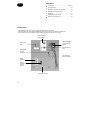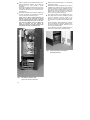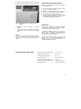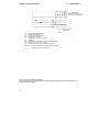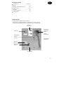
1
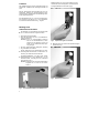
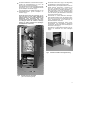
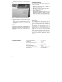
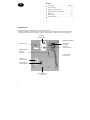
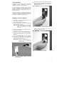
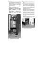
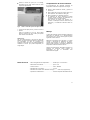
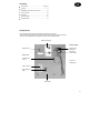
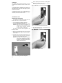
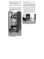
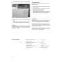
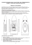
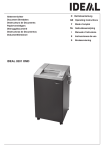
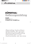
OLSBERG
Anleitung • Manual de instrucciones
Instruction Manual • Notice d’utilisation
Handleiding
Integrierter thermomechanischer Raumtemperaturregler
für die Speicherheizgeräte 14/512 bis 14/517
14/553, 14/554, 14/556
Regulador termomecánico integrado de temperatura ambiente
para los aparatos de calefacción con acumulador de calor modelos 14/512 al 14/517
14/553, 14/554, 14/556
Integral thermo-mechanical room thermostat
for Storage Heaters 14/512 to 14/517
14/553, 14/554, 14/556
Thermostat d’ambiance thermomécanique intégré
Pour les accumulateurs de chaleur électrique type 14/512 à 14/517
14/553, 14/554, 14/556
Geïntegreerde thermomechanische kamertemperatuurregelaar
voor de warmteaccumulatoren 14/512 tot 14/517
14/553, 14/554, 14/556
D
........................3 - 7
E
........................8 - 12
GB
......................13 - 17
F
......................18 - 22
NL
......................23 - 27
2
Inhaltsübersicht
• Bauteile .......................................................... Seite 3
D
• Funktion .................................................................. 4
• Montage und elektrischer Anschluss ..................... 4
• Funktionsprüfung .................................................... 6
• Bedienung............................................................... 6
• Technische Daten................................................... 6
• Schaltplan ............................................................... 7
Bauteile
Der Raumtemperaturregler besteht im wesentlichen aus:
- Einstelleinheit mit Kapillarrohrregler und Wippenschalter für Zusatzheizung
- Fühlereinheit mit Kapillarrohrfühler, Kunststoffgehäuse und Strahlenschutzblech
KunststoffSchaltblende
Einstelleinheit
Bedienknopf
Kapillarrohrregler
beleuchteter
Wippenschalter
Fühlereinheit
Kapillarrohrfühler
nicht abgebildet:
Dichtstreifen
KunststoffGehäuse
Strahlenschutzblech
Zugentlastung
3
Funktion
Der Kapillarrohrregler misst die Raumtemperatur und
schaltet den Ventilatormotor bedarfsgerecht EIN und
AUS.
Kapillarrohrregler von vorn durch die Öffnung in der
Vorderwand mit den beiliegenden Schrauben M4x6
am Reglerhalteblech anschrauben (Fig.2).
Mit dem beleuchteten Wippenschalter kann eine Zusatzheizung (Zubehör) im Speicherheizgerät eingeschaltet werden. Bei Betrieb der Zusatzheizung leuchtet der Wippenschalter auf.
Eine Nachtabsenkung um ca. 3K ist bei entsprechender Ansteuerung an Klemme TA – durch Handschalter, Schaltuhr oder Zentralsteuerung – möglich.
Montage und
elektrischer Anschluss
• Die Montage und der elektrische Anschluss dürfen
nur von einem Fachmann ausgeführt werden.
• Gerät spannungsfrei schalten.
Dazu die Stromzufuhr der Auf- und Entladestromkreise unterbrechen.
Achtung: Auch bei ausgeschalteter Sicherung
kann an den Hochtarifklemmen, insbesondere bei den Klemmen A1/Z1 und
A2/Z2 für die Aufladeautomatik, Spannung anliegen.
Fig.2
Kapillarrohrregler anschrauben
• Bedienknopf auf die Achse des Kapillarrohrreglers
aufstecken (Fig.3).
• Die dem Speicherheizgerät beiliegende Anleitung
ist grundsätzlich zu beachten.
• Rechte Seitenwand und Abdeckhaube des Speicherheizgerätes losschrauben und abnehmen. Anstanzung aus Seitenwand herausbrechen.
• Kunststoff-Schaltblende mit Hilfe eines SchlitzSchraubendrehers an den Haltelaschen, von der
Geräteinnenseite, vorsichtig aus der Vorderwand
herausknipsen (Fig.1).
Hinweis: Setzen Sie den Schlitz-Schraubendreher
möglichst nah von innen an der Vorderwand an.
Fig.3
Fig.1
4
Kunststoff-Schaltblende mit Haltelaschen
Bedienknopf aufstecken
• Kunststoff-Schaltblende mit beleuchtetem Wippenschalter und Anschlussleitungen von vorn in die
Öffnung in der Vorderwand einknipsen.
Anschlussleitungen des Wippenschalters am Kapillarrohrregler und an der Schalttafelklemmleiste
gemäß Schaltplan anschließen (Fig.4).
• Anschlussleitungen des Kapillarrohrreglers an der
Schalttafelklemmleiste gemäß Schaltplan anschließen (Fig.4).
Achten Sie darauf, dass die Leitungen so verlegt sind, dass sie keine heißen Oberflächen
berühren können, dass sie beim Montieren der
Seitenwand nicht beschädigt oder abgequetscht werden können und dass keine inneren Leitungen durch die seitlichen Lüftungsschlitze von außen berührbar sind (beiliegenden Kabelbinder verwenden).
• Flusensieb herausnehmen (Fig.4, nicht dargestellt)
und Gitterblech für Flusensieb abschrauben.
• Kapillarrohrleitung mit Kapillarrohrfühler durch den
Schlitz zwischen Vorderwand / Trennblech und
durch den Ventilatorraum führen (Fig.4). Gitterblech für Flusensieb in Stützblech einstecken und
links anschrauben. Achten Sie dabei darauf, dass
die Kapillarrohrleitung mit dem Kapillarrohrfühler
unter der Abkantung des Gitterblech für Flusensieb
nach außen geführt ist (Fig.4).
• Fühlereinheit an rechter Seitenwand befestigen.
Dazu Kapillarrohrfühler durch das Strahlenschutzblech und von innen durch die Seitenwand führen
(Fig.5). Kapillarrohrfühler in die Halterungen im
Kunststoff-Gehäuse eindrücken.
Kunststoff-Gehäuse (Seitenwand außen), Strahlenschutzblech und Zugentlastung miteinander
verschrauben. Benutzen Sie dazu die beiliegenden
Schrauben 2,9x9,5 (Fig.5).
Zugentlastung mit Befestigungsschraube des Gitterblech für Flusensieb am Gerät befestigen
(Fig.5).
Fig.5
Fig.4
Strahlenschutzblech und Zugentlastung
Kapillarrohrregler verdrahtet
(ohne Flusensieb dargestellt)
5
• Beiliegenden Dichtstreifen, von rechts beginnend,
auf die obere Abkantung der Vorderwand kleben.
Funktionsprüfung
Die Funktion des Integrierten Raumtemperaturreglers
ist wie folgt zu prüfen:
• Bedienknopf herausdrücken und in Stellung „6“
drehen. Der Ventilator läuft.
• Bedienknopf in Stellung „Linksanschlag“ drehen.
Der Ventilator darf nicht laufen.
• Nur bei Zusatzheizung:
Die Zusatzheizung lässt sich nur bei nicht aufgeladenem Speicherheizgerät einschalten.
Bedienknopf in Stellung „6“ drehen und Wippenschalter einschalten. Der Wippenschalter muss
aufleuchten und die Zusatzheizung in Betrieb sein.
Fig.6
Dichtstreifen auf Vorderwand-Abkantung
• Flusensieb einsetzen und Gerät wieder verschließen.
Achten Sie vor dem Wiederanschrauben der rechten Seitenwand darauf, dass das Flusensieb richtig
eingelegt ist.
Hinweis:
Es ist darauf zu achten, dass ein Mindestmaß von
10cm zwischen Gebäudewand und rechter Speicherheizgerätewand eingehalten wird. Die seitlichen Lüftungsschlitze dürfen nicht mit Gegenständen zugestellt werden.
Bedienung
Der Einstellbereich der Raumtemperatur liegt zwischen 7°C (Stellung „1“) und ca. 30°C (Stellung „6“)
und kann in diesem Bereich stufenlos eingestellt werden.
Durch Betätigen des Wippenschalters wird die Zusatzheizung EIN- und AUS-geschaltet. Leuchtet der
Wippenschalter auf, so ist die Zusatzheizung eingeschaltet und der integrierte Raumtemperaturregler
arbeitet.
Achtung! Mit dem Raumtemperaturregler allein kann
kein Frostschutz gewährleistet werden. Grundvoraussetzung ist ein ausreichend aufgeladenes Speicherheizgerät.
Technische Daten
- Temperatur-Einstellbereich............................ ca. 7° bis 30°C
- Schaltdifferenz................................................ ca. 1,5K
- Temperaturabsenkung über TA..................... ca. 3K
- Nennspannung ............................................... 230V ~ 50/60Hz
- Max. Anschlussleistung ................................. 10 (4) A
- Anschlussleistung Zusatzheizung ................. 230V 10A (ohmsche Last)
- Funkentstörung .............................................. Funkentstörgrad N
6
Schaltplan
1) 78/4514.5103
Klemme TA: 230V-Signal zur Temperaturabsenkung
Technische Änderungen behalten wir uns vor.
Bei Garantiefällen gelten die landesspezifischen Rechtsansprüche, die Sie bitte direkt gegenüber Ihrem
Händler geltend machen.
7
Índice
E
• Componentes ............................................. Página 7
• Funcionamiento.......................................................8
• Montaje y conexión eléctrica ..................................8
• Comprobación del funcionamiento .......................10
• Manejo ...................................................................10
• Datos técnicos.......................................................10
• Esquema eléctrico.................................................11
Componentes
El regulador de temperatura ambiente se compone esencialmente de:
- Unidad de regulación con regulador de tubo capilar e interruptor de tecla basculante para la calefacción adicional
- Unidad sensora con sensor de tubo capilar, carcasa de material sintético y chapa protectora contra radiaciones
Carátula de
material sintético
Unidad de regulación
Regulador de
tubo capilar
Botón de mando
Interruptor
con lámpara piloto
Unidad sensora
Sensor de
tubo capilar
no representado:
banda de junta
Carcasa de
material sintético
Chapa protectora
contra radiaciones
Cable de seguridad
a la tracción
8
Funcionamiento
El regulador de tubo capilar mide la temperatura
ambiente y conecta o desconecta el motor del
ventilador de acuerdo con las necesidades.
• Por delante, y a través de la abertura del frontal
anterior, atornillar el regulador de tubo capilar a la
chapa soporte del regulador, con los tornillos de
M4x6 adjuntos (Fig.2).
Con el interruptor con lámpara piloto se puede
conectar la calefacción de apoyo (accesorio) en el
aparato de calefacción con acumulador de calor.
Cuando funciona la calefacción de apoyo, el
interruptor se ilumina.
Se puede conseguir un descenso de aprox. 3K
durante la noche con la correspondiente excitación en
el borne TA - mediante un interruptor manual, reloj
conmutador o dispositivo central de mando.
Montaje y conexión eléctrica
• El montaje y la conexión eléctrica solamente los
debe realizar un profesional.
• Desconectar el aparato de la tensión.
Para ello interrumpir la entrada de corriente del
circuito de carga y descarga.
Atención: Incluso con la seguridad desconectada,
puede haber tensión en las bornas
A1/Z1 y A2/Z2 para la carga
automática.
• Tener en cuenta el manual de instrucciones que se
encuentra en el aparato.
Fig.2
Atornillado del regulador de tubo capilar
• Insertar el botón de mando sobre el eje del
regulador de tubo capilar (Fig.3).
• Desatornillar y retirar el panel lateral derecho y la
tapa del acumulador de calor. Presionar sobre la
superficie troquelada situada en la parte inferior
del panel.
• Con un destornillador plano, liberar con cuidado
las orejas de sustentación de la carátula de
material sintético que lo fijan al panel anterior del
aparato por su parte interior (Fig.1).
Observación: Coloque el destornillador por el
interior, lo más cerca posible del
frontal anterior.
Fig.3
Fig.1
Inserción del botón de mando
Carátula de material sintético con orejas
de sustentación
9
• Por delante, introducir a presión en la abertura de
la pared delantera la carátula de material sintético
junto con el interruptor con lámpara piloto y los
cables de conexión.
Conectar los cables de conexión del interruptor al
regulador de tubo capilar y a la regleta de bornes
del cuadro de distribución, de acuerdo con el
esquema eléctrico (Fig.4).
• Conectar los cables del regulador de tubo capilar a
la regleta de bornes del cuadro de distribución, de
acuerdo con el esquema eléctrico (Fig.4).
Preste atención que los cables se tiendan de
manera que no puedan tocar ninguna
superficie caliente, que al montar el panel
lateral no puedan resultar dañados o
aplastados y que a través de las rendijas de
ventilación laterales no pueda entrar en
contacto con ningún conductor interior
(utilícense las abrazaderas para cables
adjuntas).
• Extraer el filtro para pelusa (no representado en la
Fig.4) y desatornillar la chapa perforada para el
mismo.
• Pasar la conducción de tubo capilar junto con el
sensor de tubo capilar a través de la rendija entre
el panel delantero y la chapa de separación y a
través del recinto del ventilador (Fig.4). Insertar y
atornillar la chapa perforada por la izquierda para
el filtro para pelusa. Preste atención a que la
conducción de tubo capilar juntamente con el
sensor de tubo capilar queden situados hacia fuera
por debajo del rebordeado de la chapa perforada
para el filtro para pelusa (Fig.4).
• Fijar la unidad sensora al panel lateral derecho.
Para ello, pasar el sensor de tubo capilar a través
de la chapa de protección contra radiaciones y,
desde el interior, pasarlo a través del panel lateral
(Fig.5). Insertar a presión el sensor de tubo capilar
en los soportes de la carcasa de material sintético.
Atornillar entre sí la carcasa de material sintético
(panel lateral exterior), la chapa de protección
contra radiaciones y el dispositivo de descarga de
tracción. Utilice para ello los tornillos de 2,9x9,5
adjuntos (Fig.5).
Fijar el cable de seguridad a la tracción al aparato
mediante el tornillo de fijación de la chapa
perforada para el filtro para pelusa (Fig.5).
Fig.5
Fig.4
10
Regulador de tubo capilar, cableado
(representado sin el filtro para pelusa)
Chapa de protección contra radiaciones y
cable de seguridad a la tracción
• Adherir la banda de junta que se entrega,
empezando por la parte derecha hacia el borde
superior del panel frontal.
Comprobación del funcionamiento
El funcionamiento del regulador integrado de
temperatura ambiente se comprobará como sigue:
• Pulsar el botón retráctil de mando y girarlo a la
posición "6".
• Girar el botón de mando a la posición "paro en la
parte izquierda". El ventilador no debe girar.
• Sólo en aparatos con calefacción de apoyo:
La calefacción de apoyo solamente se puede
conectar cuando el aparato de calefacción con
acumulador de calor no está cargado.
Girar el botón de mando a la posición "6" y
conectar el interruptor luminoso. Este tiene que
iluminarse y la calefacción adicional estará en
servicio.
Fig.6
Junta en el borde superior del panel frontal
• Colocar el filtro para pelusa y cerrar de nuevo el
aparato.
Antes de atornillar de nuevo la panel lateral
derecho cerciórese de que el filtro para pelusa
está colocado correctamente.
Observación:
Hay que prestar atención a que entre la pared del
edificio y el panel derecho del aparato de calefacción
con acumulador de calor se mantenga una
separación mínima de 10cm. Las rendijas laterales de
ventilación no tienen que quedar bloqueadas por
ningún objeto.
Manejo
La gama de regulación de la temperatura ambiente se
sitúa entre 7°C (Posición "1") y aproximadamente
30°C (Posición "6"), y dentro de esta gama se puede
regular de manera continua.
Mediante accionamiento del interruptor, se puede
conectar y desconectar la calefacción de apoyo.
Cuando este interruptor se ilumina, la calefacción
adicional está conectada y el regulador integrado de
temperatura ambiente se halla en servicio.
Atención: El termostato de temperatura ambiente no
garantiza una protección contra heladas. La
precondición
es
que
el
acumulador
esté
suficientemente cargado.
Datos técnicos
- Gama de regulación de la temperatura .............. desde aprox. 7°C hasta 30°C
- Diferencia de conmutación.............. ................... aprox. 1,5K
- Tensión nominal.............................. ................... 230V ~ 50/60Hz
- Intensidad máx. de conexión.............................. 10 (4) A
- Intensidad de conexión de la calefacción de apoyo .......... 230V 10A (carga óhmica)
- Supresión de interferencias ................................ Grado de supresión deinterferencias: N
11
Esquema eléctrico
1) 78/4514.5103
Circuito adicional:
termostato ambiente
integrado termomecánico
Alimentación
1/N/PE~230V
B2
E2
F2.1
F2.2
F3
M1
R2.1
R2.2
SZ
Regulador integrado de temperatura ambiente
Resistencia de apoyo
Limitador para el desbloqueo
Limitador de temperatura
Limitador térmico de seguridad
Turbina
Resistencia aceleradora para termostato ambiente
Resistencia de reducción nocturna de temperatura
Interruptor luminoso para calefacción de apoyo
Modificaciones técnicas reservadas.
En caso de garantía, sólo son válidas las condiciones generales del país, de las cuales usted puede
beneficiarse junto con su comerciante.
12
Contents
GB
• Components.................................................Page 13
• Function ................................................................ 14
• Installation and electrical connection ................... 14
• Test of function ..................................................... 16
• Operation .............................................................. 16
• Technical Data...................................................... 16
• Circuit Diagram ..................................................... 17
Components
The room thermostat consists essentially of the following components:
- Setting adjuster with capillary tube thermostat and rocker switch for day-acting element
- Sensor unit with capillary sensor, plastic housing and heat-protection plate
Plastic fascia plate
Setting adjuster
Capillary-tube
thermostat
Adjuster knob
Illuminated
rocker switch
Sensor unit
Capillary tube sensor
not shown:
Sealing strip
Plastic housing
Heat-protecting
plate
Strain relief
13
Function
The capillary tube thermostat measures the room
temperature and switches the fan ON or OFF accordingly.
• Fix the capillary-tube thermostat to the fixing plate
through the opening in the front panel using the
M4x6 fixing screws supplied (Fig.2).
A day-acting element (supplied as an accessory) in
the storage heater can be switched by means of the
illuminated rocker switch. The switch lights up when
the DAE is in operation.
A night-time set back of ca. 3K can be achieved by a
control current on terminal TA, for instance by a manual switch, time-clock or central control.
Installation and
Electrical Connection
• The installation and Electrical Connection may only
be carried out by a competent electrician.
• Turn off all electricity supplies to the heater.
To do this, interrupt the electricity supply to both
the charge and the discharge circuits.
Caution! Even if the main circuit breakers are
switched off, some terminals carrying
on-peak current, especially terminals
A1/Z1 and A2/Z2 can still be live.
Fig.2
Fixing the capillary-tube thermostat
• Push the adjuster knob on to the spindle of the
capillary thermostat (Fig.3).
• Also read the Instruction Leaflet supplied with the
storage heater.
• Remove the right-hand side panel and cover panel
of the storage heater. Break out the knock-outs in
the side panel.
• Carefully remove the plastic fascia plate from the
inside of the heater front panel using a screwdriver
to gently push out the holding tabs (Fig.1).
Attention: The angle of the screwdriver should be
set as close as possible to the inside of
the front panel (oblique angle prevents
breakage of the fascia plate and/or
chipping of the paint-work).
Fig.3
Fig.1
14
Plastic fascia plate with holding tabs
Push on adjuster knob
• Clip in the plastic fascia plate with the illuminated
rocker switch and connecting cables through the
opening in the front of the heater.
Connect the cables from the rocker switch to the
capillary-tube thermostat and to the terminal strip
according to the circuit diagram (Fig.4).
• Connect the cables from capillary-tube thermostat
to the terminal strip according to the circuit diagram
(Fig.4).
Make sure that the wires are not touching any
hot surfaces, that they are neither damaged nor
squeezed when replacing the side panel and
that no internal wiring is touchable from the
outside through the air-slits (use the cable
binders provided).
• Remove the fluff filter (Fig.4, not shown) and its
corresponding fixing plate.
• Thread the capillary tubing and capillary sensor
bulb through the slit between the front panel /
separation plate and then through the fan compartment (Fig.4). Replace the fluff filter fixing plate
and screw on. Make sure that the capillary tube
and the capillary sensor bulb are thread outwards
below the edge of the fluff filter fixing plate (Fig.4).
• Fix the sensor unit to the right hand side panel.
The capillary sensor should be threaded through
the heat protection plate and front the inside
through the side panel (Fig.5). Push the capillary
sensor bulb into the bracket in the plastic housing.
Screw the plastic housing (outer side panel), heat
protection plate and strain relief together. Use the
2.9x9.5 screws provided for this purpose (Fig.5).
Fix the strain relief to the heater with the fluff filter
plate fixing screw (Fig.5).
Fig.5
Fig.4
Heat protection plate and strain relief
Wired capillary-tube
(shown without fluff filter)
15
• Fix the sealing strip supplied on to the upper edge
of the front panel, beginning at the right hand side.
Test of function
The function of the integral room thermostat is to be
tested as follows:
• Push out the adjuster knob and turn it to setting
"6“. The fan runs.
• Turn the adjuster knob to setting "stop on the lefthand side". The fan must not run.
• Only with a day-acting element:Turn the adjuster knob to setting „6“ and switch the
rocker switch to on. The rocker switch must light up
and the day-acting element must be energised.
Fig.6
Sealing strip on the front panel edge
• Replace the fluff filter and close the heater back
up.
Before fixing the right-hand side panel back on,
make sure that the fluff filter is correctly in place.
Attention:
A minimum clearance of 10cm between the right-hand
side panel and the wall of the room to be heated must
be kept. The air slits in the side panel must not be
covered by any objects.
Technical Data
Operation
The adjustment range for the room temperature lies
between 7°C (Setting „1“) and ca. 30°C (Setting „6“)
and can be infinitely varied between these settings.
By using the rocker switch the day-acting element can
be turned ON and OFF. If the rocker switch is illuminated, it shows that the DAE is switched on and that
the thermostat is functioning.
Caution! The room thermostat alone is no guarantee
of frost protection. The basic requirement for this is a
sufficient charge in the storage heater.
- Temperature setting range ............................ ca. 7° to 30°C
- Switching range ............................................. ca. 1,5K
- Temperature decrease via TA ....................... ca. 3K
- Nominal voltage.............................................. 230V ~ 50/60Hz
- Max. Power draw ........................................... 10 (4) A
- Power draw day-acting element .................... 230V 10A (resistive load)
- Noise suppression.......................................... Suppression grade N
16
Circuit Diagram
1) 78/4514.5103
Additional circuit:
Integral thermo-mechanical
room thermostat
Connection cable
1/N/PE~230V
B2
E2
F2.1
F2.2
F3
M1
R2.1
R2.2
SZ
Integral room thermostat
Day-acting element
Thermal release thermostat
Safety thermostat
Fan safety cut-out
Fan
Accelerator resistance for room thermostat
Night set-back resistance
Illuminated rocker switch for day-acting element
Terminal TA: 230V signal for temperature decrease
We reserve the right to make any technical changes.
In guarantee case the country specified rights are valid which you may claim directly towards your dealer.
17
Sommaire
F
• Composition .................................................page 18
• Fonctionnement.....................................................19
• Montage et raccordement électrique....................19
• Vérification du fonctionnement .............................21
• Utilisation ...............................................................21
• Caractéristiques techniques .................................21
• Schéma de raccordement.....................................22
Composition
Le thermostat d’ambiance se compose principalement des éléments suivants:
- Unité de réglage avec thermostat à capillaires et interrupteur lumineux pour résistance additionnelle
- Unité sonde avec sonde à capillaires, boîtier plastique et plaque de protection à la chaleur
Panneau de commande plastique
Unité de réglage
Bouton de réglage
Thermostat à capillaires
Interrupteur lumineux
Unité sonde
Sonde à
capillaires
sans illustration:
Bande hermétique
Boîtier
plastique
Tôle de
protection
contre la
chaleur
Décharge de tension
18
Fonctionnement
Le thermostat à capillaires mesure la température
ambiante et enclenche ou stoppe le moteur du ventilateur en fonction des besoins.
• Vissez le thermostat à capillaires à la plaque de
support en passant par l’ouverture de la paroi frontale à l’aide des vis M4x6 jointes (Fig.2).
Une résistance additionnelle (accessoire) peut être
mise en route à l’intérieur de l’appareil grâce à
l’interrupteur lumineux. L’interrupteur est allumé
quand la résistance fonctionne.
Il est possible d’obtenir une diminution nocturne
d’environ 3K grâce à un réglage sur la borne TA, par
exemple à l’aide d’un interrupteur manuel, d’une minuterie ou d’une régulation centrale.
Montage et raccordement électrique
• Le montage et le raccordement électrique doivent
être effectués par un professionnel.
• Coupez toute les alimentations électriques de
l’appareil, que ce soit au niveau de la charge ou de
la décharge.
Attention: Même en cas de coupure du courant, il
peut subsister de la tension à l’intérieur
de l’appareil, et particulièrement aux
bornes A1/Z1 et A2/Z2.
• Lisez également le manuel d’utilisation joint au
l’accumulateur de chaleur.
Fig.2
Vissez le thermostat à capillaires
• Fixez le bouton de réglage sur l’axe du thermostat
à capillaires (Fig.3).
• Enlevez les vis de la paroi latérale droite et du
couvercle de l’accumulateur et cassez les matrices
de la paroi droite.
• Séparez avec précaution la plaque de raccordement plastique de la paroi frontale interne de
l’appareil à l’aide d’un tournevis pour décoller les
supports (Fig.1).
Conseil: Rapprochez le tournevis le plus possible
de l’intérieur de la paroi frontale de
l’appareil.
Fig.3
Fig.1
Fixez le bouton de réglage
Panneau de commande plastique avec
supports
19
• Clipser la plaque de raccordement plastique comprenant l’interrupteur lumineux et les câbles de
raccordement à la paroi frontale à travers
l’ouverture.
Raccordez les câbles de l’interrupteur lumineux au
thermostat à capillaires et à la borne du tableau de
raccordement conformément au schéma de branchement (Fig.4).
• Raccordez les câbles du thermostat à capillaires à
la borne du tableau de raccordement conformément au schéma de branchement (Fig.4).
Veillez que les câbles soient positionnés de
manière à ce qu’ils ne soient pas en contact
avec des surfaces chaudes, qu’ils ne puissent
pas être endommagés ou pincés lors du montage de la paroi latérale et que les câbles intérieurs ne puissent pas être atteints de
l’extérieur à travers les canaux d’aération latéraux. Utilisez les liens des câbles fournis.
• Retirez le filtre à impuretés (Fig.4, non représenté)
et dévissez sa grille.
• Faites passer le câble à capillaires avec la sonde à
capillaires dans l’espace entre la paroi frontale et
la tôle de séparation à travers l’habitacle du ventilateur (Fig.4). Fixez la grille du filtre dans la tôle de
protection et vissez-la. Vérifiez que le câble à capillaires avec la sonde soit passé vers l’extérieur
sous le coin de la grille du filtre (Fig.4).
• Fixez l’unité sonde à la paroi latérale droite. Pour
cela, faites passer la sonde à capillaires à travers
la tôle de protection contre la chaleur et de
l’intérieur à travers la paroi latérale (Fig.5). Poussez la sonde sur les supports dans le boîtier plastique.
Vissez ensemble le boîtier plastique (à l’extérieur
de la paroi latérale), la plaque de protection thermique et la décharge de traction. Utilisez pour cela
les vis 2,9x9,5 fournies (Fig.5).
Fixez la décharge de tension à l’appareil grâce aux
fixations de la grille du filtre à impuretés (Fig.5).
Fig.5
Fig.4
20
Thermostat à capillaires relié
(représenté sans filtre à impuretés)
Plaque de protection thermique et
décharge de tension
• Collez la bande hermétique fournie en partant de
la droite sur l'arête supérieure de la paroi frontale.
Vérification du fonctionnement
Vérifiez le fonctionnement du thermostat d’ambiance
de la manière suivante:
• Tirez sur le bouton de réglage et mettez-le en position „6“. Le ventilateur fonctionne.
• Mettez le bouton de réglage en position „arrêt à la
gauche“. Le ventilateur ne doit pas fonctionner.
• Si vous avez une résistance additionnelle:
Placez le bouton de réglage en position „6“ et enclenchez l’interrupteur lumineux. L’interrupteur doit
être allumé et la résistance fonctionner.
Fig.6
Bande hermétique sur l'arête de la paroi
frontale
• Replacez le
l’appareil.
filtre
à
impuretés
et
refermez
Veillez à ce que le filtre à impuretés soit correctement installé avant de revisser la paroi latérale
droite.
Conseil:
Vérifiez qu’il y a un espace d’au moins 10cm entre le
mur de votre pièce et la paroi latérale droite. De
même, ne recouvrez pas les canaux de sortie d’air
latéraux.
Caractéristiques techniques
Utilisation
Le créneau de réglage de la température ambiante
est situé entre 7°C (position „1“) et env. 30°C (position
„6“) et peut être réglé de manière linéaire.
La résistance additionnelle sera mise en marche ou
stoppée grâce à l’interrupteur lumineux. Si l’interrupteur est allumé, la résistance additionnelle est en
marche et le thermostat fonctionne.
Attention! Une protection contre le gel ne peut être
obtenue avec le seul thermostat d'ambiance. La
condition sine qua non de cette protection est un accumulateur suffisamment chargé.
- Créneau de réglage de température ........ env. 7° à 30°C
- Différence de branchement ...................... env. 1,5K
- Abaissement de température ................... env. 3K
- Tension nominale...................................... 230V ~ 50/60Hz
- Puissance de raccordement max ............. 10 (4) A
- Puissance (résistance additionnelle)........ 230V 10A (charge)
- Réduction du bruit..................................... Degré de réduction N
21
Schéma de raccordement
1) 78/4514.5103
Circuit additionnel:
Thermostat d’ambiance
thermomécanique intégré
Câble Connexion
1/N/PE~230V
B2
E2
F2.1
F2.2
F3
M1
R2.1
R2.2
SZ
Thermostat d’ambiance intégré
Résistance additionnelle
Thermostat de déclenchement
Thermostat de sécurité
Thermostat de sécurité du ventilateur
Ventilateur
Résistance de compensation pour thermostat d’ambiance
Résistance pour diminution nocturne
Interrupteur lumineux pour résistance additionnelle
Borne TA: Commande d’abaissement de température automatique
par horloge de programmation par ex.
Sous réserve de modifications techniques.
En cas de garantie, ne sont valables que les conditions générales du pays, que vous pouvez faire valoir
auprès de votre commerçant.
22
Inhoudsoverzicht
NL
• Componenten ...........................................Pagina 23
• Functie .................................................................. 24
• Montage en elektrische aansluiting...................... 24
• Functiecontrole ..................................................... 26
• Bediening .............................................................. 26
• Technische gegevens........................................... 26
• Schakelschema .................................................... 27
Componenten
De kamertemperatuurregelaar bestaat in principe uit:
- Insteleenheid met capillaire buisregelaar en wipschakelaar voor extra verwarming
- Voelereenheid met capillaire buisvoeler, kunststof behuizing en bevestigingshouder
Kunststof
schakelpaneel
Insteleenheid
Bedienknop
Capillaire buisregelaar
Verlichte
wipschakelaar
Voelereenheid
Capillaire
buisvoeler
Niet afgebeeld:
afdichtstroken
Kunststofbehuizing
Bevestigingshouder
Snoerontlasting
23
Functie
De capillaire buisregelaar meet de kamertemperatuur
en schakelt de motor van de ventilatormotor naar
behoefte AAN en UIT.
De capillaire buisregelaar van voren door de opening
in de voorwand steken en met de bijgevoegde
schroeven M4x6 aan de houdplaat van de regelaar
vastschroeven (Fig.2).
Met de verlichte wipschakelaar kan een extra
verwarming (accessoires) in de warmteaccumulator
ingeschakeld worden. Tijdens het gebruik van de
extra verwarming is de wipschakelaar verlicht.
Een nachtverlaging van ca. 3K is bij een passende
aansturing aan klem TA – door handschakelaar,
schakelklok of centrale aansturing – mogelijk.
Montage en
elektrische aansluiting
• De montage en elektrische aansluiting mogen
uitsluitend door een vakman uitgevoerd worden.
• Apparaat spanningsvrij schakelen.
Hiervoor de stroomtoevoer van de op- en
ontlaadstroomcircuits onderbreken.
Attentie: Ook als de zekering uitgeschakeld is,
kan er op de klemmen voor hoog tarief,
vooral bij de klemmen A1/Z1 en A2/Z2
voor de oplaadregeling, spanning
staan.
• De bij de warmteaccumulator bijgevoegde
montagehandleiding dient te worden opgevolgd.
Fig. 2 Capillaire buisregelaar vastschroeven
• Bedienknop op de as van de capillaire buisregelaar
steken (Fig.3).
• Rechter
zijwand
en
afdekkap
van
de
warmteaccumulator losschroeven en verwijderen.
Ingestanst gedeelte uit de zijwand breken.
• Kunststof schakelpaneel voorzichtig uit de
voorwand duwen door vanuit de binnenkant van
het apparaat de vasthoudstrips met behulp van
een sleufschroevendraaier weg te drukken (Fig.1).
Instructie: Zet de sleufschroevendraaier van
binnen uit zo dicht mogelijk tegen de
voorwand aan.
Fig. 3 Bedienknop opsteken
Fig. 1 Kunststof schakelpaneel met
vasthoudstrips
24
• Kunststof schakelpaneel met de verlichte
wipschakelaar en de aansluitleidingen in de
opening van de voorwand drukken
Aansluitleidingen van de wipschakelaar aan de
capillaire buisregelaar en aan de klemlijst
aansluiten volgens het schakelschema (Fig.4).
• Aansluitleidingen van de wipschakelaar aan de
capillaire buisregelaar en aan de klemlijst
aansluiten volgens het schakelschema (Fig.4).
Let erop dat de leidingen zodanig gelegd zijn
dat ze niet in aanraking kunnen komen met
hete oppervlakken, dat ze bij het monteren van
de zijwand niet beschadigd of afgeklemd
kunnen worden en dat de ventilatieopeningen
aan de zijkant niet van buitenaf aangeraakt
kunnen worden (bijgevoegde kabelbinder
gebruiken).
• Pluizenzeef eruit halen (Fig.4, niet afgebeeld) en
roosterplaat voor pluizenzeef losschroeven.
• De capillaire buisleiding met de capillaire
buisvoeler door de sleuf tussen voorwand /
scheidingsplaat en de ventilatorruimte leiden
(Fig.4). Roosterplaat voor pluizenzeef in de
steunplaat steken en links vastschroeven. Let er
hierbij op dat de capillaire buisleiding met de
capillaire buisvoeler onder de rand van de
roosterplaat voor het pluizenzeef naar buiten
geleid is (Fig.4).
• Voelereenheid aan de rechter zijwand bevestigen.
Hiervoor moet de capillaire buisvoeler door de
bevestigingshouder en van binnen door de zijwand
geleid worden (Fig.5). De capillaire buisvoeler in
de houders van de kunststof behuizing drukken.
Kunststof
behuizing
(zijwand
buitenkant),
bevestigingshouder en snoerontlasting aan elkaar
vastschroeven. Maak hiervoor gebruik van de
bijgevoegde schroeven 2,9x9,5 (Fig.5).
Snoerontlasting met bevestigingsschroef van de
roosterplaat voor het pluizenzeef aan het apparaat
bevestigen (Fig.5).
Fig. 5 Bevestigingshouder en snoerontlasting
Fig. 4 Capillaire buisregelaar bedraad
(zonder pluizenzeef afgebeeld)
25
• De bijgevoegde afdichtstroken, rechts beginnend,
op de bovenste rand van de voorwand plakken.
Functiecontrole
De functie van de geïntegreerde
kamertemperatuurregelaar moet als volgt
gecontroleerd worden:
• Bedienknop naar buiten drukken en op stand „6“
draaien. De ventilator loopt.
• Bedienknop op stand „linker aanslag“ draaien.
De ventilator mag niet lopen.
• Uitsluitend bij extra verwarming:
De extra verwarming kan uitsluitend ingeschakeld
worden als de warmteaccumulator niet opgeladen
is.
Bedienknop op stand „6“ draaien en de
wipschakelaar inschakelen. De wipschakelaar
moet verlicht zijn en de extra verwarming moet in
gebruik zijn.
Fig. 6 Afdichtstroken op de rand van de
voorwand
• Pluizenzeef inzetten en het apparaat weer sluiten.
Voordat u de rechter zijwand weer vastschroeft,
moet u erop letten dat het pluizenzeef correct
geplaatst is.
Instructie:
Er moet op gelet worden dat er tussen de muur van
het gebouw en de rechterwand van de
warmteaccumulator een minimale afstand van 10cm
aangehouden wordt. De ventilatieopeningen aan de
zijkant mogen niet geblokkeerd worden door
eventuele voorwerpen.
Bediening
Het instelbereik van de kamertemperatuur ligt tussen
7°C (stand „1“) en ca. 30°C (stand „6“) en kan
traploos binnen dit bereik ingesteld worden.
Door op de wipschakelaar te drukken wordt de extra
verwarming AAN en UIT gezet. Als de wipschakelaar
verlicht is, dan is de extra verwarming ingeschakeld
en werkt de geïntegreerde kamertemperatuurregelaar.
Attentie! Alleen met de kamertemperatuurregelaar is
geen bescherming tegen vorst gegarandeerd. De
voornaamste
voorwaarde
hiervoor
is
een
warmteaccumulator die voldoende opgeladen is.
Technische gegevens
- Temperatuur-instelbereik............................... ca. 7° tot 30°C
- Schakeldifferentie........................................... ca. 1,5K
- Temperatuurverlaging via TA ........................ ca. 3K
- Nominale spanning ........................................ 230V ~ 50/60Hz
- Max. aansluitvermogen.................................. 10 (4) A
- Aansluitvermogen extra verwarming ............. 230V 10A (ohmse last)
- Radio ontstoring ............................................. Radio ontstoringsgraad N
26
Schakelschema
1) 78/4514.5103
Extra schakeling:
Ingebouwde
thermomechanische
kamertemperatuurregelaar
kabel
B2 Geïntegreerde kamertemperatuurregelaar
E2 Extra verwarming
F2.1 Regelaar vrijgave extra verwarming
F2.2 Oververhittingsbeveiliging extra verwarming
F3 Temperatuursensor ventilator
M1 Ventilator
R2.1 Compensatieweerstand kamertemperatuurregelaar
R2.2 Weerstand voor verlaging van de kamertemperatuur
SZ Verlichte wipschakelaar voor extra verwarming
Klem TA: 230V signaal voor temperatuurverlaging
Technische wijzigingen voorbehouden.
Bij garantiegevallen gelden de landspecifieke wettige aanspraken, die u rechtstreeks bij uw handelaar kunt
kenbaar maken.
27
10/2008
www.olsberg.com
5) 78/4614.5103
Hüttenstraße 38 • D - 59939 Olsberg
Telefon +49 / (0) 29 62 / 8 05 – 0
Telefax
+49 / (0) 29 62 / 8 05 – 180
Email
[email protected]