1
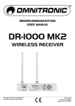
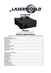
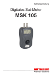
® Vertrieb von JTS-Produkten — Distribution of JTS products Bedienungsanleitung Instruction Manual Mode d’emploi Manual de instrucciones UA-902 Antennenverteiler Antenna Splitter Répartiteur d’antenne Repartidor de antena 2 DEUTSCH Bevor Sie einschalten … ENGLISH Before switching on … FRANÇAIS Avant toute installation … ESPAÑOL Antes de cualquier instalación ... Wir wünschen Ihnen viel Spaß mit Ihrem neuen Gerät von JTS. Bitte lesen Sie diese Bedienungsanleitung vor dem Betrieb gründlich durch. Nur so lernen Sie alle Funktionsmöglichkeiten kennen, vermeiden Fehlbedienungen und schützen sich und Ihr Gerät vor eventuellen Schäden durch unsachgemäßen Gebrauch. Heben Sie die Anleitung für ein späteres Nachlesen auf. We wish you much pleasure with your new JTS unit. Please read these operating instructions carefully prior to operating the unit. Thus, you will get to know all functions of the unit, operating errors will be prevented, and yourself and the unit will be protected against any damage caused by improper use. Please keep the operating instructions for later use. Nous vous souhaitons beaucoup de plaisir à utiliser cet appareil JTS. Lisez ce mode dʼemploi entièrement avant toute utilisation. Uniquement ainsi, vous pourrez apprendre lʼensemble des possibilités de fonctionnement de lʼappareil, éviter toute manipulation erronée et vous protéger, ainsi que lʼappareil, de dommages éventuels engendrés par une utilisation inadaptée. Conservez la notice pour pouvoir vous y reporter ultérieurement. Le deseamos una buena utilización para su nuevo aparato de JTS. Por favor, lea estas instrucciones de uso atentamente antes de hacer funcionar el aparato. De esta manera conocerá todas las funciones de la unidad, se prevendrán errores de operación, usted y el aparato estarán protegidos en contra de todo daño causado por un uso inadecuado. Por favor, guarde las instrucciones para una futura utilización. POWER UA-900 UHF ANTENNA DISTRIBUTION SYSTEM 1 2 4 5 3 1 6 5 DC OUTPUT ANT. A ANT. A OUTPUT 12V CONNECT TO RECEIVER 1 2 ANT. B OUTPUT 3 4 4 3 ANT. B 2 1 DC OUTPUT 12V CONNECT TO RECEIVER 230V~/ 50Hz 6 7 8 7 ANTENNA A IN ANTENNA B IN DC OUTPUT ANT. A ANT. A OUTPUT 12V CONNECT TO RECEIVER 1 2 ANT. B OUTPUT 3 4 4 3 ANT. B 2 1 DC OUTPUT 12V CONNECT TO RECEIVER 230V~/ 50Hz UA-902 POWER SUPPLY ANTENNA A OUT 1 ANTENNA A OUT 2 POWER SUPPLY ANTENNA B OUT 1 12-18V 200mA AF OUTPUT UNBAL. AF OUTPUT BAL. ANT. 2 ANT. 1 US-9001D/2 ANTENNA B OUT 2 12-18V 200mA AF OUTPUT UNBAL. AF OUTPUT BAL. ANT. 2 ANT. 1 US-9001D/2 ANTENNA A OUT 3 ANTENNA B OUT 3 12-18V 200mA AF OUTPUT UNBAL. AF OUTPUT BAL. ANT. 2 ANT. 1 US-9001D/2 ANTENNA A OUT 4 ANTENNA B OUT 4 12-18V 200mA AF OUTPUT UNBAL. AF OUTPUT BAL. ANT. 2 ANT. 1 US-9001D/2 POWER SUPPLY POWER SUPPLY 3 DEUTSCH Auf der ausklappbaren Seite 3 finden Sie alle beschriebenen Bedienelemente und Anschlüsse. 1 Verwendungsmöglichkeiten Der Antennenverteiler UA-902 ist für den Betrieb von bis zu vier UHF-Empfängern von JTS (US-..., IN-... oder UF-...), die über abnehmbare Antennen verfügen, vorgesehen. Er vereinfacht den Aufbau der AudioÜbertragungsanlage: Von den Antennen die jedem Empfänger beiliegen (ein Paar pro Empfänger) werden nur zwei zum Anschluss an den Antennenverteiler benötigt, alle übrigen Antennen sowie die Netzgeräte der Empfänger sind nicht erforderlich; die Empfänger erhalten die Antennensignale und ihre Stromversorgung über den Verteiler. Passende Anschlusskabel werden mitgeliefert. Der Antennenverteiler kann auch in Verbindung mit zwei als Zubehör von JTS erhältlichen Antennenverstärkern UB-900 / 2 genutzt werden. Er stellt über seine Antenneneingänge die Stromversorgung für die Verstärker bereit. 2 Hinweise für den sicheren Gebrauch Dieses Gerät entspricht allen relevanten Richtlinien der EU und ist deshalb mit gekennzeichnet. WARNUNG Das Gerät wird mit lebensgefährlicher Netzspannung versorgt. Nehmen Sie deshalb nie selbst Eingriffe am Gerät vor. Durch unsachgemäßes Vorgehen besteht die Gefahr eines elektrischen Schlages. ENGLISH Beachten Sie auch unbedingt die folgenden Punkte: G Das Gerät ist nur zur Verwendung im Innenbereich geeignet. Schützen Sie es vor Tropf- und Spritzwasser, hoher Luftfeuchtigkeit und Hitze (zulässiger Einsatztemperaturbereich 0 – 40 °C). G Stellen Sie keine mit Flüssigkeit gefüllten Gefäße, z. B. Trinkgläser, auf das Gerät. G Nehmen Sie das Gerät nicht in Betrieb bzw. ziehen Sie sofort den Netzstecker aus der Steckdose: G G Soll das Gerät endgültig aus dem Betrieb genommen werden, übergeben Sie es zur umweltgerechten Entsorgung einem örtlichen Recyclingbetrieb. 3 Inbetriebnahme Der Antennenverteiler kann frei aufgestellt oder in ein Rack für Geräte mit einer Breite von 482 mm (19″) eingesetzt werden. Für den Rackeinbau wird 1 HE (Höheneinheit) = 44,45 mm benötigt. Für die Antennenmontage an der Front die zwei beiliegenden BNC-Doppelbuchsen durch jeweils das linke und das rechte Montageloch der Frontplatte stecken und festschrauben → siehe Abb. 4. 1) Die Kleinspannungsbuchsen DC OUTPUT (5) mit den Stromversorgungsbuchsen der Empfänger verbinden. 2) Das Antennenpaar von einem der Empfänger bzw. zwei Antennenverstärker mit ihren aufgesteckten Antennen an die Antenneneingänge des Verteilers anschließen: – entweder an die beiden Buchsen (1) auf der Gerätevorderseite; in diesem Fall die rückseitigen Buchsen (6) mit den Buchsen ANT. A und ANT. B (7) verbinden (wie in Abb. 3 zu sehen) All operating elements and connections described can be found on the fold-out page 3. 1 Applications The antenna splitter UA-902 is designed for operating up to four UHF receivers from JTS (US-..., IN-... or UF-...) equipped with detachable antennas; it will make it easier to set up the audio transmission system: Only two of the antennas supplied with each receiver (one pair for each receiver) are required for connection to the antenna splitter; all other antennas and the power supply units of the receivers are not required. The receivers are provided with the antenna signals and with power via the splitter. Matching connection cables are supplied. The antenna splitter can also be used in connection with two antenna amplifiers UB-900 / 2 available as accessories from JTS. Via its antenna inputs, it supplies power to the amplifiers. 2 Safety Notes This unit corresponds to all relevant directives of the EU and is therefore marked with . WARNING The unit is supplied with hazardous mains voltage. Leave servicing to skilled personnel only. Inexpert handling may cause an electric shock hazard. Please observe the following items in any case: G The unit is suitable for indoor use only. Protect it against dripping water and splash water, high air humidity, and heat (admissible ambient temperature range 0 – 40 °C). G Do not place any vessel filled with liquid on the unit, e. g. a drinking glass. G Do not operate the unit or immediately disconnect the plug from the mains socket 1. if there is visible damage to the unit or to the mains cable, 2. if a defect might have occurred after the unit was 4 G 1. wenn sichtbare Schäden am Gerät oder am Netzkabel vorhanden sind, 2. wenn nach einem Sturz oder Ähnlichem der Verdacht auf einen Defekt besteht, 3. wenn Funktionsstörungen auftreten. Lassen Sie das Gerät in jedem Fall in einer Fachwerkstatt reparieren. Ziehen Sie den Netzstecker nie am Kabel aus der Steckdose, fassen Sie immer am Stecker an. Verwenden Sie für die Reinigung nur ein trockenes, weiches Tuch, niemals Wasser oder Chemikalien. Wird das Gerät zweckentfremdet, nicht richtig angeschlossen oder nicht fachgerecht repariert, kann keine Haftung für daraus resultierende Sach- oder Personenschäden und keine Garantie für das Gerät übernommen werden. G G G G dropped or suffered a similar accident, 3. if malfunctions occur. In any case the unit must be repaired by skilled personnel. Never pull the mains cable for disconnecting the mains plug from the socket, always seize the plug. For cleaning only use a dry, soft cloth; never use chemicals or water. No guarantee claims for the unit and no liability for any resulting personal damage or material damage will be accepted if the unit is used for other purposes than originally intended, if it is not correctly connected, or not repaired in an expert way. Important for U. K. Customers! The wires in this mains lead are coloured in accordance with the following code: green/yellow = earth, blue = neutral, brown = live. As the colours of the wires in the mains lead of this appliance may not correspond with the coloured markings identifying the terminals in your plug, proceed as follows: 1. The wire which is coloured green and yellow must be connected to the terminal in the plug which is marked with the letter E or by the earth symbol , or coloured green or green and yellow. 2. The wire which is coloured blue must be connected to the terminal which is marked with the letter N or coloured black. 3. The wire which is coloured brown must be connected to the terminal which is marked with the letter L or coloured red. Warning - This appliance must be earthed. If the unit is to be put out of operation definitively, take it to a local recycling plant for a disposal which is not harmful to the environment. – oder direkt an die beiden Buchsen ANT. A und ANT. B (7) auf der Geräterückseite 3) Die beiden Antenneneingänge an jedem Empfänger jeweils mit einem Antennenausgang ANT. A OUTPUT und dem entsprechenden Antennenausgang ANT. B OUTPUT (8) verbinden → siehe Abb. 3. 4) Zum Schluss das beiliegende Netzkabel an die Netzbuchse (4) anschließen und den Netzstecker des Kabels in eine Steckdose (230 V~/50 Hz) stecken. 5) Zum Ein-/Ausschalten des Antennenverteilers die Taste POWER (3) drücken. Bei eingeschaltetem Gerät leuchtet die Betriebsanzeige (2). Wird das Gerät längere Zeit nicht benötigt, sollte der Netzstecker aus der Steckdose gezogen werden. Anderenfalls wird auch bei ausgeschaltetem Gerät stets ein geringer Strom verbraucht. 4 Technische Daten Frequenzbereich: . . . . . . . Stromversorgung: . . . . . . . Antennenanschlüsse: . . . . Abmessungen (B × H × T): Gewicht: . . . . . . . . . . . . . . 470 – 870 MHz 230 V~/50 Hz/25 VA BNC-Buchsen 482 × 44 × 260 mm, 1 HE 3,1 kg Änderungen vorbehalten. Diese Bedienungsanleitung ist urheberrechtlich für MONACOR ® INTERNATIONAL GmbH & Co. KG geschützt. Eine Reproduktion für eigene kommerzielle Zwecke – auch auszugsweise – ist untersagt. For mounting the antennas at the front, insert the two supplied BNC double jacks through the corresponding left and right mounting holes of the front panel and screw them on → see fig. 4. 1) Connect the low voltage jacks DC OUTPUT (5) to the power supply jacks of the receivers. 2) Connect the antenna pair of one of the receivers or two antenna amplifiers, with their antennas attached, to the antenna inputs of the splitter: – either to the two jacks (1) at the front of the unit; in this case, connect the rear jacks (6) to the jacks ANT. A and ANT. B (7) [see fig. 3]. – or directly to the two jacks ANT. A and ANT. B (7) at the rear side of the unit 3) Connect the two antenna inputs on each receiver respectively to an antenna output ANT. A OUTPUT and the corresponding antenna output ANT. B OUTPUT (8) → see fig. 3. 4) Finally connect the supplied mains cable to the mains jack (4) and the mains plug of the cable to a socket (230 V~/50 Hz). 5) To switch the antenna splitter on or off, press the button POWER (3). With the unit switched on, the power LED (2) lights up. If the unit is not used for a longer period, disconnect the mains plug from the socket; otherwise, there will be a low power consumption even with the unit switched off. 4 Specifications Frequency range: . . . . . . . Power supply: . . . . . . . . . . Antenna connections: . . . . Dimensions (W × H × D): . Weight: . . . . . . . . . . . . . . . 470 – 870 MHz 230 V~/50 Hz/25 VA BNC jacks 482 × 44 × 260 mm, 1 RS 3.1 kg 3 Operation Subject to technical modification. The antenna splitter can be placed as desired or installed into a rack for units of a width of 482 mm (19″). For rack installation, 1 RS (rack space) = 44.45 mm is required. All rights reserved by MONACOR ® INTERNATIONAL GmbH & Co. KG. No part of this instruction manual may be reproduced in any form or by any means for any commercial use. Ne faites pas fonctionner lʼappareil et débranchez-le immédiatement lorsque : 1. le cordon secteur ou lʼappareil présente des dommages. 2. après une chute ou accident similaire, lʼappareil peut présenter un défaut. 3. des dysfonctionnements apparaissent. Dans tous les cas, faites appel à un technicien spécialisé pour effectuer les réparations. G Ne débranchez jamais lʼappareil en tirant sur le cordon secteur, tenez-le toujours par la fiche. G Pour nettoyer lʼappareil, utilisez uniquement un chiffon sec et doux, en aucun cas de produit chimique ou dʼeau. G Nous déclinons toute responsabilité en cas de dommages matériels ou corporels résultants si lʼappareil est utilisé dans un but autre que celui pour lequel il a été conçu, sʼil nʼest pas correctement branché ou réparé par un technicien habilité ; en outre, la garantie deviendrait caduque. 1 Possibilités dʼutilisation Le répartiteur dʼantenne UA-902 est conçu pour le fonctionnement de quatre récepteurs UHF maximum de JTS (US-..., IN-... ou UF-...) équipés dʼantennes démontables. Il facilite le montage du système de transmission audio: seules deux parmi les antennes fournies avec chaque récepteur (une paire par récepteur) sont nécessaires pour brancher au répartiteur dʼantenne, toutes les autres antennes et les alimentations secteur des récepteurs ne sont pas nécessaires ; les récepteurs reçoivent les signaux dʼantenne et leur alimentation via le répartiteur. Les cordons de liaison sont livrés. Le répartiteur dʼantenne peut également être utilisé, combiné à deux amplificateurs dʼantenne UB-900 / 2 de marque JTS, disponibles en option. Il met à disposition via ses entrées dʼantenne lʼalimentation pour les amplificateurs. Lorsque lʼappareil est définitivement retiré du service, vous devez le déposer dans une usine de recyclage de proximité pour contribuer à son élimination non polluante. 2 Conseils dʼutilisation et de sécurité Lʼappareil répond à toutes les directives importantes de lʼUnion européenne et porte donc le symbole . AVERTISSEMENT Lʼappareil est alimenté par une tension dangereuse. Ne touchez jamais lʼintérieur de lʼappareil car vous pourriez subir une décharge électrique dangereuse. Respectez scrupuleusement les points suivants : G Lʼappareil nʼest conçu que pour une utilisation en intérieur. Protégez-le de tout type de projections dʼeau, des éclaboussures, dʼune humidité élevée de lʼair et de la chaleur (plage de température de fonctionnement autorisée : 0 – 40 °C). G En aucun cas, vous ne devez poser dʼobjet contenant du liquide ou un verre sur lʼappareil. A pagina 3, se aperta completamente, vedrete sempre gli elementi di comando e i collegamenti descritti. 3 Fonctionnement 2 Notas de seguridad Esta unidad corresponde a todas las Directivas relevantes de la UE y por ello está marcada con . ADVERTENCIA La unidad se alimenta con un voltaje de red peligroso. Deje el mantenimiento sólo en manos de personal especializado. Una manipulación inexperta puede causar un riesgo de shock eléctrico. Por favor, fíjese en los puntos siguientes en cualquier caso: G La unidad sólo está indicada para un uso en interior. Protéjala de goteos y salpicaduras de agua, de la humedad elevada del aire y del calor (gama de temperatura ambiente admisible: 0 – 40 °C). G No coloque ningún recipiente con líquido sobre la unidad, p. ej. un vaso de bebida. 4 Caractéristiques techniques Bande passante : . . . . . . . Alimentation : . . . . . . . . . . Connexions antenne : . . . . Dimensions (L × H × P) : . . Poids : . . . . . . . . . . . . . . . . 470 – 870 MHz 230 V~/50 Hz/25 VA prises BNC 482 × 44 × 260 mm, 1 U 3,1 kg Tout droit de modification réservé. Le répartiteur dʼantenne peut être posé librement ou placé dans un rack prévu pour appareils dʼune largeur de 482 mm (19″). Pour une installation en rack, une unité (1 U) = 44,45 mm est nécessaire. Pour le montage des antennes sur la face avant, insérez les deux prises doubles BNC dans respectivement le trou de montage gauche et le trou de montage droit de la face avant et vissez, voir schéma 4. 1) Reliez les prises basse tension DC OUTPUT (5) aux prises dʼalimentation des récepteurs. 2) Reliez la paire dʼantennes dʼun des récepteurs ou deux amplificateurs dʼantenne, avec leurs antennes placées, aux entrées dʼantenne du répartiteur : G No utilice la unidad o desconecte inmediatamente el enchufe de la toma de red 1. en caso de daño visible en la unidad o en el cable de red, 2. si ha ocurrido un defecto después de que la unidad haya sufrido una caída o un accidente similar, 3. si ocurren disfunciones. En cualquier caso la unidad sólo debe ser reparada por personal especializado. G No tire nunca del cable de red para desconectar el enchufe de red de la toma, tire siempre del enchufe. G Para limpiar use sólo un paño seco y suave, no utilice agua o productos químicos. G No se asumirá ninguna garantía para la unidad y no se aceptará ninguna responsabilidad en caso de daños personales o patrimoniales causados si la unidad se usa para otros fines distintos a los originalmente concebidos, si no se conecta correctamente, o si no se repara de manera experta. 1 Aplicaciones El repartidor de antena UA-902 se diseña para funcionar hasta cuatro receptores UHF de JTS (US-..., IN-... o UF-...) equipados de las antenas desmontables; será más fácil instalar el sistema audio de transmisión: Solamente se necesitan dos de las antenas entregadas con cada receptor (un par para cada receptor) para la conexión al repartidor de antena; el resto de las antenas y las unidades de alimentación de los receptores no son necesarias. Los receptores se aprovisionan de las señales de antena y de la alimentación vía el repartidor de antena. Se entrega con los cables de conexión. El repartidor de antena también se puede usar conectándolo a dos amplificadores de antena UB-900 / 2 disponibles como accesorios de JTS. Mediante sus entradas de antena, suministra potencia a los amplificadores. – soit aux deux prises (1) sur la face avant ; dans ce cas, reliez les prises de la face arrière (6) aux prises ANT. A et ANT. B (7) [voir schéma 3]. – soit directement aux deux prises ANT. A et ANT. B (7) sur la face arrière de lʼappareil. 3) Reliez les deux entrées dʼantenne sur chaque récepteur respectivement à une sortie dʼantenne ANT. A OUTPUT et à la sortie dʼantenne correspondante ANT. B OUTPUT (8) – voir schéma 3. 4) Pour finir, reliez le cordon secteur livré à la prise secteur (4) et reliez la fiche secteur du cordon à une prise secteur 230 V~/50 Hz. 5) Pour allumer/éteindre le répartiteur dʼantenne, enfoncez la touche POWER (3). Lorsque lʼappareil est allumé, le témoin de fonctionnement (2) brille. En cas de non utilisation prolongée, débranchez le cordon secteur de la prise car même éteint, lʼappareil a une faible consommation. FRANÇAIS G Si la unidad debe ser retirada del funcionamiento definitivamente, llévela a un centro de reciclaje local para su disposición no contaminante para el medio ambiente. 3 Funcionamiento El repartidor de antena se puede colocar como se desee o instalarlo en un rack para unidades de anchura de 482 mm (19″). Para la instalación rack se necesita 1 RS (espacio rack) = 44,45 mm. Para montar las antenas en el frontal, inserte los dos jacks dobles BNC entregados a través de los agujeros de montaje izquierdo y derecho correspondientes del panel frontal y atornillarlos → vea la figura 4. 1) Conecte los jacks de bajo voltaje DC OUTPUT (5) a los jacks de alimentación de los receptores. 2) Conecte la pareja de antenas de uno de los receptores o dos amplificadores de antena, con sus antenas unidas, a las entradas de antena del repartidor: Notice d'utilisation protégée par le copyright de MONACOR ® INTERNATIONAL GmbH & Co. KG. Toute reproduction même partielle à des fins commerciales est interdite. – o bien a los dos jacks (1) en el frontal de la unidad; en ese caso, conecte los jacks traseros (6) a los jacks ANT. A y ANT. B (7) [vea la figura 3]. – o directamente a los dos jacks ANT. A y ANT. B (7) en la parte trasera de la unidad 3) Conecte las dos entradas de antena en cada receptor respectivamente a una salida de antena ANT. A OUTPUT y la salida de antena correspondiente ANT. B OUTPUT (8) → vea la figura 3. 4) Finalmente, conecte el cable de red al jack de red (4) y el enchufe de red del cable a una toma (230 V~ /50 Hz). 5) Para encender o apagar el repartidor de antena, presione el botón POWER (3). Con la unidad encendida se enciende el LED de encendido (2). Si no se va a usar la unidad durante un largo periodo de tiempo, se recomienda desconectar el enchufe de red de la toma de red. De otro modo, incluso con la unidad apagada, siempre habrá un pequeño consumo. ESPAÑOL Vous trouverez sur la page 3, dépliable, les éléments et branchements décrits. 4 Características técnicas Gama de frecuencia: . . . . . Alimentación: . . . . . . . . . . . Conexiones de antena: . . . Dimensiones (B × H × P): . Peso: . . . . . . . . . . . . . . . . . 470 – 870 MHz 230 V~/50 Hz/25 VA jacks BNC 482 × 44 × 260 mm, 1 RS 3,1 kg Sujeto a modificaciones técnicas. Manual de instrucciones protegido por el copyright de MONACOR ® INTERNATIONAL GmbH & Co. KG. Toda reproducción incluida parcial con fines comerciales está prohibida. 5 www.jts-germany.de MONACOR INTERNATIONAL GmbH & Co. KG, Zum Falsch 36, 28307 Bremen, Germany Copyright © by MONACOR INTERNATIONAL. All rights reserved. A-1341.99.01.05.2012