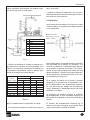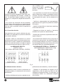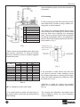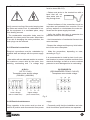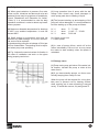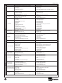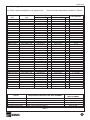
1
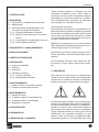
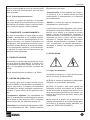
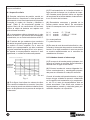
DECLARACIÓN DE CONFORMIDAD
Nosotros, EBARA ESPAÑA BOMBAS, S.A.,
declaramos bajo nuestra responsabilidad que
nuestros productos "ENR" (suministrados con
motor ya instalado) son conformes con la
Directiva de Máquinas 98/37/CEE y la
Directiva que la modificó 98/79/CEE; con la
Directiva de Baja Tensión 73/23/CEE y su
modificación Directiva 93/68/CEE; y con la
Directiva de Compatibilidad Electromagnética
89/336/CEE y su modificación Directiva
93/68/CEE.
KONFORMITAETSERKLARUNG
Wir, EBARA ESPAÑA BOMBAS, S.A., erklären
unter unserer Verantwortung, dass unsere
Erzeugnisse "ENR" (schon mit installiertem
Motor geliefert) mit der Maschinenvorschift
98/37/CEE wie von den Norm 98/79/CEE abgeändert übereinstimimen, sowie sie auch mit der
Richtlinie über Tiefspannung 73/23/CEE wie
von der Richtlinie 93/68/CEE abgeändert und
mit der Vorschrift über elektromagnetische
Verträglichkeit 89/336/CEE wie von der Norm
93/68/CEE abgeändert übereinstimrnen.
DECLARATION OF CONFORMITY
We, EBARA ESPAÑA BOMBAS, S.A., declare
under our own responsibility that our products
"ENR" (supplied with motor already installed)
conform to the Machinery Directive 98/37/CEE
as modified by Directive 98/79/CEE, to the
Low Tension Directive 73/23/CEE, as modified
by Directive 93/68/CEE and to the
Electromagnetic Compatibility Directive
89/336/CEE as modified by Directive
93/68/CEE.
DICHIARAZIONE DI CONFORMITÁ
Noi, EBARA ESPAÑA BOMBAS, S.A., dichiariamo sotto la nostra responsabilitá che i ns.
prodotti "ENR" (forniti con motore giá installato) sono in conformitá alla Direttiva Macchine
98/37/CEE come modificato dalla direttiva
98/79/CEE, alla Diretiva Bassa Tensione
73/23/CEE come modificato dalla direttiva
93/68/CEE e alla Direttiva Compatibilitá
Elettromagnetica 89/336/CEE come modifícate dalla direttiva 93/68 CEE.
DÉCLARATION DE CONFORMITÉ
Nous soussignons, EBARA ESPAÑA BOMBAS, S.A., déclarons sous notre responsabilité
que nos produits "ENR" (fournis ávec le moteur
deja installé) sont conformes à la Directive sur
les Machines 98/37/CEE comme modifiée par
la Directive 98/79/CEE, à la Directive sur la Tension Basse 73/23/CEE, comme modifiée par la
Directive 93/68/CEE et à la Directive sur la
Compatibilité Electromagnétique 89/336/CEE
comme modifiée par la Directive 93/68/CEE.
DECLARAÇAO DE CONFORMIDADE
Nós, EBARA ESPAÑA BOMBAS, S.A., declaramos sobra nossa responsabilidade que, os
produtos "ENR" sao em conformidades á
Diretriz Macchine 98/37/CEE, sendo modificado da Diretriz 98/79/CEE, a Diretriz Baixa
Tensao 73/23/CEE, sendo modificado da
Diretriz 93/68/CEE e a Diretriz de Compatibilidade Electromagnética 89/336/CEE sendo
modificada da Diretriz 93/68/CEE.
ANGEL DÍAZ
Director General
Pinto, 09-02-05
(ESPAÑOL)
ÍNDICE
1.-INTRODUCCIÓN
2.-SEGURIDAD
2.1.- Preparación y cualificación del personal
2.2.- Manipulación
2.3.- Instrucciones de seguridad para el uso
en áreas con peligro de explosión
2.3.1.- Grupos motobombas completos
2.3.2.- Ejecución de protecciones de acoplamiento
2.3.3.- Comprobación de parámetros técnicos
2.3.4.- Evitar impactos externos
3.-TRANSPORTE Y ALMACENAMIENTO
4.-ESPECIFICACIONES
5.-LÍMITES DE OPERACIÓN
6.-INSTALACIÓN
6.1.- Lugar de instalación
6.2.- Tuberías
6.3.- Alineación
6.4.- Instalación eléctrica
6.4.1.- Conexión eléctrica
6.4.2.- Mantenimiento eléctrico
7.-FUNCIONAMIENTO
7.1.- Antes de poner en marcha la bomba
7.2.- Puesta en marcha de la bomba
8.-MANTENIMIENTO
8.1.- Inspección diaria
8.2.- Cuidados durante el funcionamiento
8.3.- Cuidados durante el almacenaje
8.4.- Reposición de piezas
9.-CONSTRUCCIÓN
10.-DESMONTAJE
11.-REPARACIÓN Y GARANTÍA
1.- INTRODUCCIÓN
Todos nuestros equipos se entregan una vez
verificados en fábrica y, por lo tanto, están en
condiciones de funcionar correctamente tras ser
efectuadas las conexiones eléctricas e hidráulicas correspondientes, siguiendo las instrucciones expuestas en el presente manual.
A la recepción del equipo:
(1) Comprobar las placas de características. Es
particularmente importante comprobar la tensión
de utilización (voltaje) de la bomba. Verificar además el valor de la altura de impulsión, el caudal
y la velocidad de giro de las bombas, así como el
consumo máximo de los motores.
(2) Revisar el equipo para ver si se ha producido
algún desperfecto ocasionado durante el envío, o
si existe algún tornillo o tuerca flojos.
(3) Verificar que se han recibido todos los accesorios, repuestos y elementos opcionales que se
pidieron.
Se recomienda conservar este manual de instrucciones en lugar seguro para futuras consultas.
2.- SEGURIDAD
Este manual de instrucciones y mantenimiento
contiene instrucciones básicas, las cuales deberán tenerse en cuenta al hacerse la instalación,
puesta en marcha y mantenimiento del equipo.
Peligro indefinido
Tensión eléctrica
Es absolutamente necesario que el operario/instalador lea cuidadosamente todos los apartados
de este manual antes de hacer la instalación y
puesta en marcha. Será conveniente mantener
este manual en el lugar en el que va a trabajar el
equipo. Deberán tenerse en cuenta, junto con las
indicaciones de seguirdad indicadas en este
manual, todas las normas de seguridad reglamentarias vigentes en el país donde vaya a ser
3
(ESPAÑOL)
utilizado el equipo para una protección más
segura.
La omisión de las instrucciones de seguridad del
presente manual puede causar peligros para las
personas y para el equipo.
2.1 Preparación y cualificación del personal
El personal de instalación, servicio, mantenimiento e inspección del equipo deberá estar perfectamente cualificado para este tipo de trabajo.
La responsabilidad, competencia y supervisión
del personal será asumida por el propietario. El
personal deberá ser preparado en el caso de no
tener los suficientes conocimientos. Si se solicita,
el propietario recibirá la preparación adecuada
de mano de EBARA o del distribuidor de este
equipo.
2.2 Manipulación
Las modificaciones técnicas o los cambios en la
estructura del equipo no están permitidos sin
haber sido discutidos con EBARA. Solamente las
piezas de repuesto originales y otros accesorios
autorizados por EBARA son adecuados para
cumplir con las normas de seguridad. Reconstruir, modificar o utilizar otras piezas de recambio
puede invalidar la garantía.
El buen funcionamiento del equipo esta únicamente asegurado cuando éste se utiliza de la
forma especificada en este manual de instrucciones. Tanto las condiciones de trabajo como
los límites estipulados en este manual no pueden
en ningún caso ser sobrepasados.
Mantener las placas de características del equipo en buen estado y siempre legibles, estos
datos serán necesarios para cualquier consulta o
solicitud de repuestos.
2.3 Instrucciones de seguridad para el uso en
áreas con peligro de explosión
En este apartado se da información para un funcionamiento en áreas con peligro de explosión.
4
2.3.1 Grupos motobombas completos
Si la bomba está funcionando con otros componentes eléctricos o mecánicos formando un equipo, la categoría de la unidad completa corresponderá, según la Directiva 94/9/EC, sólo a
aquella categoría con la cual cumplan todos los
componentes.
Nota:
Este comentario es de particular importancia
cuando bombas que cumplen con una categoría
dada de la Directiva 94/9/EC están acopladas a
un accionamiento que no cumple con la misma
categoría.O sea, que aunque la bomba puede
llevar la marca Ex, el equipo no será usado en
áreas con peligro de explosión si el motor y el
resto de componentes no están clasificados para
esta aplicación.
Esto significa que el personal responsable de
planta tiene siempre que comprobar que todos
los elementos que constituyan el equipo cumplan
con la Directiva 94/9/EC.
2.3.2 Ejecución de protecciones de acoplamiento
Las protecciones de acoplamiento que vayan a
ser usadas en áreas con peligro de explosión,
tienen que cumplir con uno de los siguientes criterios:
• Estar fabricadas con material antichispa, por
ejemplo latón.
• Si están fabricadas con materiales que pueden
producir chispa, como acero inoxidable, tienen
que estar diseñadas de tal manera que las partes
giratorias no puedan entrar en contacto con ninguna parte de la protección aunque se produzcan
errores previsibles por parte del usuario, como
que una persona se suba sobre la protección.
2.3.3 Comprobación de parámetros técnicos
Cuando se utilicen bombas en áreas con peligro
de explosión el usuario tiene que comprobar los
siguientes parámetros regularmente:
• Fugas de los cierres de eje
• Temperatura de cojinetes
• Que la bomba está siempre llena de líquido
durante la operación
• Que la bomba no trabaja contra una válvula
cerrada por un largo espacio de tiempo.
El operador tiene que asegurarse de que bombas que muestran evidencias de un funciona-
(ESPAÑOL)
miento anormal sean puestas fuera de servicio y
que no serán puestas de nuevo en marcha hasta
que la causa del funcionamiento anormal haya
sido eliminada.
2.3.4 Evitar impactos externos
En áreas con peligro de explosión, el operador
tiene que asegurar que las bombas y/o el equipo
de bombeo no estarán sujetos a impactos externos, como, por ejemplo, objetos pesados.
3.- TRANSPORTE Y ALMACENAMIENTO
En caso de necesidad, el equipo debe ser transportado y almacenado en un embalaje apropiado. Se debe evitar su almacenamiento en ambientes húmedos con fuertes fluctuaciones de
temperatura, o en atmósferas corrosivas. La condensación puede afectar a las zonas de sellado,
a los componentes metálicos y al funcionamiento eléctrico. En este caso las reclamaciones por
garantía serán rechazadas.
grados de humedad relativa más elevados a
temperaturas más bajas.
-Contaminación: El aire ambiente será limpio y
no corrosivo, o en su defecto tendrá una baja
contaminación y eléctricamente no conductora
por condensación.
-Altitud: La altitud del lugar de instalación no
sobrepasará los 1000 metros.
Condiciones de empleo diferentes a las expuestas deberán indicarse a EBARA; tales como instalación en el exterior o en lugares de acceso
público, valores de temperatura, humedad, y
altitud diferentes a los descritos, contaminación
importante por polvo, humos, vapores o sales,
exposición a campos eléctricos o magnéticos
intensos, emplazamientos expuestos a explosión, a vibraciones y a choques importantes, o
expuestos a ataques por hongos o pequeños
animales.
6.- INSTALACIÓN
4.- ESPECIFICACIONES
Comprobar, en la placa de características, el valor de la altura de impulsión (H), el caudal (Q) y
la velocidad de la bomba (RPM), así como el voltaje y la intensidad de corriente nominales del
motor.
6.1 Lugar de instalación
Otras especificaciones se indican en la Tabla 1.
(1) Instalar el equipo en un lugar de fácil acceso
para la revisión y el mantenimiento.
5.- LÍMITES DE OPERACIÓN
En general, salvo que se haya indicado previamente a EBARA, el equipo debe ser instalado en
interior (bajo techo), en locales suficientemente
ventilados y de acceso restringido a personal autorizado, y operar dentro de los siguientes límites:
-Temperatura ambiente: No sobrepasará los
40ºC y la temperatura media durante un periodo
de 24 horas no será superior a 35ºC. La temperatura mínima del aire ambiente será de 4ºC.
-Humedad: La humedad no sobrepasará el 50%
a una temperatura de 40ºC. Pueden admitirse
(2) Evitar el acceso de personas no autorizadas
mediante los cerramientos adecuados.
(3) Situar el equipo lo más cerca posible del
suministro de agua, procurando que la diferencia de altura entre la superficie del agua y el eje
de la bomba (altura geométrica) sea mínima, y la
longitud de la tubería de aspiración sea lo más
corta posible.
(4) La suma de la presión en la aspiración y la
presión manométrica de la bomba siempre debe
ser inferior a la máxima presión admisible (ver
cuadro de “ESPECIFICACIONES”).
5
(ESPAÑOL)
Gama
Fluidos
Materiales
Construcción
Accionamiento
Accesorios
Opcional
ESPECIFICACIONES
Tamaño nominal de las bocas, DN
32 ~ 350 (DIN 2532 PN10, EN 1092-2)
Velocidad máxima
3000 r.p.m./50 Hz ~ 3600 r.p.m./60 HZ
Caudal máximo / Presión máxima
2000 m3/h - 150 m.c.a.
Características
Líquidos limpios
Temperatura
-20 ~ +120ºC
+120 ~ +170ºC
14 / 9(1) / 8(2) bar
Máxima presión admisible
16 / 10(1) / 14(2) bar
Cuerpo de impulsión
Fundición GG25
Impulsor
Fundición GG25
Bronce G-CuSn10
Eje
Acero inoxidable AISI 420 (1.4021)
Camisa del eje
Acero inoxidable AISI 420 (1.4021)
Tipo de impulsor
Cerrado radial
Rodamientos
De bolas engrasados
Estanqueidad del eje
Cierre mecánico: Carburo de Silicio / Carbón / EPDM(3)
Motor
Eléctrico, explosión, turbina de vapor
Bancada común
Con motor
Acoplamiento
Protector de acoplamiento
Estanqueidad del eje
Empaquetadura: Fibra de lino / PTFE
Rodamientos
De bolas lubricados por aceite
Acoplamiento
Acoplamiento con espaciador
Bridas
Norma ANSI 150
(1)
Desde tamaño de bomba 80-400 hasta 300-500, excepto 150-500
Tamaño 150-500
(3)
Comprobar límites de aplicación según el líquido bombeado
(2)
Tabla 1
6.2 Tuberías
(1) Evitar que las tuberías de aspiración y de
impulsión trasmitan esfuerzos a la bomba,
mediante la instalación de soportes suficientemente resistentes, de lo contrario la bomba
podría desalinearse e incluso romperse.
(2) Instalar válvulas de retención (entre la bomba y la válvula de impulsión) en los siguientes
casos:
- En tuberías de gran longitud.
- Cuando la altura manométrica sea elevada.
- Cuando el funcionamiento sea automático.
- Cuando se abastece a un depósito a presión.
- Cuando el funcionamiento sea en paralelo.
(3) Instalar válvulas de aireación en los puntos de
la instalación donde sea imposible evitar la formación de bolsas de aire. No obstante, no deben
instalarse en puntos donde la presión sea menor
que la presión atmosférica, ya que la válvula
aspirará aire en vez de expulsarlo.
6
(4) Para reducir el efecto de un golpe de agua
(golpe de ariete), instalar una válvula de retención con muelle.
(5) Instalaciones en aspiración (ver Fig. 1):
- El extremo inferior de la tubería de aspiración
debe estar sumergido a una profundidad de, al
menos, dos veces el diámetro de la tubería (2D)
y a una distancia del fondo de 1 o 1.5 veces este
diámetro (1~1.5D).
- Instalar una válvula de pie con filtro al comienzo de la tubería de aspiración para evitar la entrada de cuerpos extraños.
- La tubería de aspiración se instalará con una
pendiente ascendente hacia la bomba (mayor
que 1%) para evitar la formación de bolsas de
aire. Las uniones entre tuberías y otros accesorios se llevarán a cabo de manera que no se produzca aspiración de aire a través de ellas.
- Procurar que la tubería de aspiración sea lo
(ESPAÑOL)
más corta y recta posible, tratando de evitar curvas y recorridos innecesarios. No instalar ninguna válvula de corte en este tramo.
la tubería de aspiración para facilitar el desmontaje y la revisión.
- Instalar la tubería de aspiración con una pendiente descendente hacia la bomba para evitar la
formación de bolsas de aire.
6.3 Alineación
Las bombas suministradas con motor son unidas
a éste mediante un acoplamiento elástico sencillo
o con espaciador.
Nº
1
2
3
4
5
6
7
8
Descripción
Bomba
Motor
Soporte
Manguito elástico
Válvula de retención
Válvula de corte
Válvula de pie
Reducción excéntrica
Fig. 2
Fig. 1
- Utilizar los tamaños de tubería de aspiración y
de reducciones excéntricas recomendadas en la
Tabla 2. La reducción excéntrica se instalará con
la pendiente ascendente hacia la bomba para
evitar la formación de bolsas de aire.
Tamaño de
1500 r.p.m.
3000 r.p.m.
bomba
Tamaño
Tamaño
øasp. x øimp. Tubería Reducción Tubería Reducción
50 x 32
65
65x50
80
80x50
65 x 40
80
80x65
100
100x65
65 x 50
100
100x65
125
125x65
80 x 65
125
125x80
150
150x80
100 x 80
150
150x100
200
200x100
125 x 100
200
200x125
250
250x125
150 x 125
250
250x150
300
300x150
200 x 150
300
300x200
-------
Tabla 2
(6) En instalaciones con aspiración en carga:
- Se recomienda instalar una válvula de corte en
Las bombas salen al mercado después de haber
sido alineadas en la fábrica; sin embargo, a la
hora de su instalación, la bancada suele alabearse al apretar los pernos de anclaje. Por lo tanto,
ajustar la bancada introduciendo debajo de ésta
galgas metálicas, y alinear la bomba manteniendo las distancias y diferencias dentro de los límites señalados en la figura 2.
Si la compra se realizó sin el motor y piensan
acoplarlo en el momento de la instalación, corrijan la desalineación del acoplamiento insertando una placa fina por debajo de las patas del
motor, ajustando su disparidad dentro del límite
señalado en la figura.
La alineación se practica quitando el protector
del acoplamiento, si bien se deberá reponer sin
falta antes de la puesta en funcionamiento de la
bomba.
El tamaño del acoplamiento depende de la
potencia del motor acoplado a la bomba. Para
mayor información consultar a EBARA.
7
(ESPAÑOL)
6.4 Instalación eléctrica
- Hacer llegar los cables a la caja de bornas con
una curvatura que
impida que el agua
penetre resbalando
por éstos.
Verificar la correcta refrigeración del motor manteniendo despejadas las entradas y salidas de
aire. Se aconseja instalar el equipo en un lugar
aireado y en una posición alejada de fuentes de
calor.
- Los orificios de evacuación de las condensaciones deben estar situados en la parte baja del
motor. Cuando no sea perjudicial para la protección del motor, se podrán retirar los tapones de
evacuación.
6.4.1 Conexión eléctrica
- Las superficies de contacto de las conexiones
deben mantenerse limpias y protegidas contra la
corrosión. No poner ni arandelas ni tuercas entre
los terminales del motor y los de entrada de la
red.
- Verificar la estanqueidad del prensaestopas,
garantizando así el grado de protección indicado
en la placa.
- Impedir la transmisión de tensiones mecánicas
a los bornes del motor.
- Respetar los límites de tensión y frecuencia
indicados en la placa de características.
Las operaciones de conexión eléctrica del equipo deben ser realizadas por personal cualificado
y sin tensión eléctrica.
- Realizar las conexiones, dependiendo del caso,
según la figura 3.
- Emplear cables de alimentación de sección
suficiente para conducir la corriente máxima consumida por el motor, evitando así sobrecalentamiento y/o caída de tensión (la caída de tensión
en la fase de arranque debe ser inferior al 3%).
- Se recomienda la instalación de un disyuntor de
cortocircuito, para prevenir los posibles accidentes de descarga eléctrica, así como un protector
de sobrecarga específico para motores con el fin
de impedir daños por sobrecalentamiento.
A) ARRANQUE DIRECTO
(HASTA 5.5 kW)
Motor trifásico doble tensión (230/400V y 400/690V)
B) ARRANQUE ESTRELLA - TRIÁNGULO
(RECOMENDADO A PARTIR DE 5.5 kW)
Motor trifásico doble tensión
Tensión inferior
Tensión superior
(CONEXION TRIANGULO)
(CONEXION ESTRELLA)
Fig. 3
6.4.2 Mantenimiento eléctrico
pecificaciones de instalación y conexión eléctrica.
Toda operación sobre el motor se efectuará con
el equipo parado y en desconexión de la red de
alimentación.
- Respetar la periodicidad de engrase de los
rodamientos y tipo de grasa (en caso de venir
reflejado en la placa del motor). En todo caso, es
conveniente sustituir los rodamientos después
de tres años.
- Verificar periódicamente que se respetan las es-
8
(ESPAÑOL)
7.- FUNCIONAMIENTO
7.1 Antes de poner en marcha la bomba
(1) Comprobar que la bomba gira suavemente,
haciendo girar el eje con la mano. Si el movimiento fuese duro o irregular, revisar la bomba ya
que el cierre mecánico podría estar dañado, la
empaquetadura demasiado apretada o existir
oxidación en el interior de la bomba.
(2) En la ejecución con lubricación de los rodamientos por baño de aceite, llenar el soporte de
los cojinetes con aceite hasta la marca indicada
en el nivel de aceite. Se utilizará un aceite mineral o sintético SAE 15W / 20W o equivalente.
Se recomienda sustituir el aceite una vez al año
cuando la temperatura de funcionamiento no sea
elevada (aprox. 50ºC). Cuando la temperatura
sea elevada y/o cuando puedan penetrar partículas extrañas en el interior del soporte de los cojinetes, la sustitución del aceite se llevará a cabo
con una mayor periodicidad atendiendo al estado
del aceite.
(3) Comprobar la intensidad máxima de funcionamiento del motor, reflejada en la placa de
características.
(4) No poner en marcha la bomba sin haber sido
cebada previamente. Si la instalación está en
aspiración, se llenará de agua tanto la bomba
como la tubería de aspiración a través del dispositivo instalado, a tal efecto, en la tubería de
impulsión. Si la aspiración está en carga, la
bomba se llenará de agua abriendo las válvulas
de aspiración y de impulsión. Procurar que no
quede aire dentro de la bomba, para lo cual se
hará girar el eje con la mano.
dos, y después pararlo.
- Comprobar visualmente que el sentido de giro
es el correcto mediante el acoplamiento o el ventilador del motor. El sentido de giro está indicado
mediante una flecha en el cuerpo de la bomba;
como norma general éste es en sentido horario
(a derechas) cuando el observador está situado
en el lado del motor.
- Cuando se haya desmontado el protector del
acoplamiento, montarlo seguidamente a la comprobación del sentido de giro.
7.2 Puesta en marcha de la bomba
(1) Cerrar la válvula de impulsión. Abrir la válvula de aspiración si ésta estuviese cerrada.
(2) Conectar y desconectar, una o dos veces, el
interruptor de puesta en marcha del motor para
comprobar que no existen anomalías en el arranque.
(3) Cuando el régimen de giro se estabilice en la
velocidad nominal, abrir la válvula de impulsión
gradualmente.
(4) Comprobar que no se producen fluctuaciones
considerables en la presión que da la bomba y
en el consumo de corriente del motor, y que no
hay grandes vibraciones y/o ruidos extraños. Se
recomienda mantener las llaves de corte del
manómetro y del manovacuómetro cerradas
excepto en el momento de tomar las mediciones.
(5) Cuando no esté instalada una válvula de
retención en la tubería de impulsión, cerrar gradualmente la válvula de impulsión antes de parar
el motor.
(6) Para posteriores arranques proceder de la
misma manera, si todas las condiciones de funcionamiento son normales, atendiendo a las indicaciones expuestas en capítulo de “MANTENIMIENTO”.
(5) Verificar el sentido de giro del motor mediante los siguientes pasos:
8.- MANTENIMIENTO
- Cerrar las válvulas de impulsión y de aspiración.
- Poner en marcha el motor durante 1 ó 2 segun-
Asegurarse de que el interruptor de funcionamiento está desconectado a la hora de realizar
operaciones de mantenimiento; la bomba podría
9
(ESPAÑOL)
arrancar repentinamente en el caso de funcionamiento automático.
8.1 Inspección diaria
(1) Grandes variaciones de presión, caudal, corriente eléctrica, vibraciones o ruidos pueden ser
síntomas de un mal funcionamiento de la bomba.
Consultar el cuadro de “Averías y Medidas a
tomar” (Tabla 3). Se recomienda guardar un
registro diario de las condiciones de funcionamiento al objeto de detectar con rapidez cualquier síntoma de avería.
(2) La temperatura máxima tolerada por el rodamiento es de 40º C por encima de la temperatura ambiente, con un límite total máximo de 80º C.
(3) El sellado del eje mediante cierre mecánico
no admite ninguna fuga de agua. Si esto ocurriese sustituir el cierre completo. En el caso de
sellado por empaquetadura se debe mantener
un goteo moderado de agua (20 ml / min. aprox.).
No apretar la empaquetadura excesiva o desigualmente, o cuando la bomba esté parada.
8.2 Cuidados durante el funcionamiento
(1) El funcionamiento de la bomba durante un
largo periodo de tiempo con la válvula de impulsión cerrada puede producir daños en algunas
de las piezas de la bomba debido al calentamiento en el interior de la misma.
(2) Demasiados arranques y paradas de la
bomba pueden causar daños. Se recomienda
limitar los arranques como se indica a continuación:
N≤6
N≤4
N≤3
cuando
cuando
cuando
P ≤ 7,5 kW
11 kW ≤ P ≤ 22 kW
P>22 kW
N = arranques/hora
P = potencia motor
(3) En caso de corte de suministro eléctrico, desconectar el interruptor de puesta en marcha de la
bomba. Si se deja conectado el motor se pondrá
en marcha repentinamente en el momento de
restablecerse el mismo.
8.3 Cuidados durante el almacenaje
(1) El cuerpo de la bomba puede quebrarse si el
agua de su interior se congela. Aislar la bomba o
evacuar todo el agua de su interior.
(2) Si tienen bombas de reserva háganlas funcionar ocasionalmente y manténgalas preparadas para ser utilizadas en cualquier momento.
Fig. 4
(4) En la figura 4 se indican los valores de vibración cuando la instalación es correcta. Una vibración excesiva puede ser debida a tuberías forzadas o al aflojamiento de los pernos de anclaje de
la bancada.
10
Cuando la bomba esté parada durante un largo
tiempo tengan cuidado de prevenir oxidaciones
en la superficie del rodamiento, eje, acoplamiento, etc. En el caso de empaquetadura ésta se
puede enmohecer. Para evitar esto, extraer la
empaquetadura, secarla y untarla de grasa, procediendo después a su reposición.
(ESPAÑOL)
Síntomas
No arranca el motor
No se puede cebar
la bomba
La bomba gira pero
no sale agua
BOMBA
No se logra el caudal
nominal
Al inicio sale agua
pero enseguida se
corta
Se produce una
sobreintensidad
Calentamiento del
rodamiento
Vibración
Excesivo ruido de
funcionamiento
Excesiva pérdida de
agua por el cierre del
eje
MOTOR
No gira
Ruidos anormales o
excesivas vibraciones
Temperatura elevada.
Aparición de humo
y/o mal olor
Velocidad de giro
baja
Causas
Medidas a tomar
- El cuadro de control no reúne las condiciones de arranque.
- Avería del motor.
- Anomalías en la alimentación eléctrica.
- Roce en el eje de rotación. Agarrotamiento.
- Cuerpos extraños en el impulsor.
- Cuerpo extraños en la válvula de pie.
- Desgaste en el asiento de la válvula de pie.
- Pérdida de agua por la tubería de aspiración.
- Entrada de aire por la tubería de aspiración o por el cierre del eje.
- La bomba no está cebada.
- La válvula de compuerta está cerrada o semicerrada.
- Excesiva altura de aspiración.
- El sentido de giro no es el correcto.
- Velocidad de giro baja.
- Tensión baja.
- Obstrucción el la válvula de pie o en el filtro.
- Obstrucción en el impulsor.
- Obstrucción en la tubería.
- Existe entrada de aire.
- Existen fugas en la tubería de impulsión.
- Desgaste del impulsor.
- Pérdida de carga en la instalación muy grandes.
- Temperatura de liquido muy alta. El líquido es volátil.
- Existencia de cavitación.
- La bomba no está cebada lo suficiente.
- Existe entrada de aire.
- Existen bolsas de aire en la tubería de aspiración.
- La altura de aspiración es demasiado alta para la bomba.
- El voltaje es bajo y el desequilibrio entre cada fase, grande.
- Bomba para 50 Hz está siendo utilizada en 60 Hz.
- Existen cuerpos extraños dentro de la bomba.
- El cierre mecánico no está bién montado.
- Deterioros en los rodamientos.
- Roces en las zonas de rotación. El eje está retorcido.
- Alta densidad y/o viscosidad del líquido.
- Deterioros en los rodamientos.
- Funcionamiento durante largo tiempo con la válvula cerrada.
- Instación defectuosa.
- Deterioros en los rodamientos.
- Caudal elevado.
- Caudal pequeño.
- Obstrucción en el impulsor.
- Sentido de giro incorrecto.
- Roces en las zonas de rotación. El eje está retorcido.
- Existencia de cavitación.
- Vibraciones en la tubería.
- El cierre mecánico no está bién montado.
- El cierre mecánico está dañado.
- Sobrepresión en la impulsion.
- El eje está retorcido.
- La bobina está rota.
- Cortocircuito en la bobina.
- La bobina está conectada a tierra.
- Los rodamientos están bloqueados.
- El voltaje es bajo.
- No hay fases en la fuente de alimentación eléctrica.
- Fallo en alguna fase de la fuente de alimentación eléctrica.
- Alto desequilibrio de voltaje.
- Roces entre el rotor y el estator.
- Hay cuerpos extraños en el ventilador de refrigeración.
- Motor mal instalado.
- Alto desequilibrio de voltaje.
- Vía de ventilación cerrada.
- Error en el voltaje.
- Los rodamientos están bloqueados.
- Cortocircuito en la bobina.
- La bobina está conectada a tierra.
- El voltaje es bajo.
- Sobreintensidad.
- Conexión eléctrica incorrecta.
- Revisar todas las condiciones.
- Reparar el motor.
- Revisar y reparar.
- Girarlo con la mano. Recomponerlo. Repararlo en taller especializado.
- Eliminar los cuerpos extraños.
- Eliminar los cuerpos extraños.
- Sustituir la válvula.
- Revisar la tubería de aspiración.
- Revisar la tubería de aspiración y el cierre del eje.
- Cebar la bomba.
- Abrir la válvula.
- Revisar el proyecto.
- Corregir la conexión eléctrica.
- Medir con un tacómetro.
- Revisar la fuente de alimentación eléctrica.
- Eliminar los cuerpos extraños.
- Eliminar los cuerpos extraños.
- Eliminar los cuerpos extraños.
- Revisar y reparar la tubería de aspiración y el cierre del eje.
- Revisar y reparar.
- Sustituir el impulsor.
- Revisar el proyecto.
- Revisar el proyecto.
- Consultar a expertos.
- Cebar la bomba.
- Revisar y reparar la tubería de aspiración y el cierre del eje.
- Reinstalar la tubería.
- Revisar el proyecto.
- Revisar la fuente de alimentación eléctrica.
- Comprobar la placa de características.
- Eliminar los cuerpos extraños.
- Montarlo correctamente
- Sustituir los rodamientos.
- Repararlo en taller especializado.
- Revisar el proyecto.
- Sustituir los rodamientos.
- Evitar dicha situación.
- Revisar la instalación
- Sustituir los rodamientos.
- Reducir la apertura de la válvula de impulsión.
- Aumentar la apertura de la válvula de impulsión.
- Eliminar los cuerpos extraños.
- Comprobar y corregir la conexión.
- Repararlo en taller especializado.
- Consultar a expertos.
- Reformar la tubería.
- Montarlo correctamente.
- Sustituir el cierre mecánico.
- Revisar el proyecto.
- Repararlo en taller especializado.
- Repararla en taller especializado.
- Repararla en taller especializado.
- Repararla en taller especializado.
- Reparar lo rodamientos.
- Cambiar el voltaje nominal.
- Revisar la fuente de alimentación eléctrica.
- Revisar la fuente de alimentación eléctrica.
- Corregir el desequilibrio de voltaje.
- Alinear y/o cambiar el rodamiento.
- Eliminar los cuerpos extraños.
- Alinear el motor con la bomba.
- Corregir el desequilibrio de voltaje.
- Eliminar las causas del cierre.
- Cambiar el motor por otro con el voltaje correcto.
- Reparar lo rodamientos.
- Repararla en taller especializado.
- Repararla en taller especializado.
- Cambiar el voltaje nominal.
- Reducir la intensidad.
- Corregir la conexión eléctrica.
Tabla 3
11
(ESPAÑOL)
de las piezas susceptibles de sustitución.
Sustituirlas según se recomienda en la Tabla 5.
8.4 Reposición de piezas
En la Tabla 4 se indican la cantidad y el tamaño
Tamaño de
bomba
ENR 32-125
ENR 32-160
ENR 32-200
ENR 32-250
ENR 40-125
ENR 40-160
ENR 40-200
ENR 40-250
ENR 40-315
ENR 50-125
ENR 50-160
ENR 50-200
ENR 50-250
ENR 50-315
ENR 65-125
ENR 65-160
ENR 65-200
ENR 65-250
ENR 65-315
ENR 80-160
ENR 80-200
ENR 80-250
ENR 80-315
ENR 80-400
ENR 100-160
ENR 100-200
ENR 100-250
ENR 100-315
ENR 100-400
ENR 125-200
ENR 125-250
ENR 125-315
ENR 125-400
ENR 150-200
ENR 150-250
ENR 150-315
ENR 150-400
ENR 200-250
Cierre
mecánico
DIN 24960- ø24
DIN 24960- ø24
DIN 24960- ø24
DIN 24960- ø24
DIN 24960- ø24
DIN 24960- ø24
DIN 24960- ø24
DIN 24960- ø24
DIN 24960- ø32
DIN 24960- ø24
DIN 24960- ø24
DIN 24960- ø24
DIN 24960- ø24
DIN 24960- ø32
DIN 24960- ø24
DIN 24960- ø24
DIN 24960- ø24
DIN 24960- ø32
DIN 24960- ø32
DIN 24960- ø24
DIN 24960- ø32
DIN 24960- ø32
DIN 24960- ø32
DIN 24960- ø45
DIN 24960- ø32
DIN 24960- ø32
DIN 24960- ø32
DIN 24960- ø32
DIN 24960- ø45
DIN 24960- ø32
DIN 24960- ø32
DIN 24960- ø45
DIN 24960- ø45
DIN 24960- ø32
DIN 24960- ø32
DIN 24960- ø45
DIN 24960- ø45
DIN 24960- ø45
Empaquetadura
Tamaño
ø32xø48x8
ø32xø48x8
ø32xø48x8
ø32xø48x8
ø32xø48x8
ø32xø48x8
ø32xø48x8
ø32xø48x8
ø40xø60x10
ø32xø48x8
ø32xø48x8
ø32xø48x8
ø32xø48x8
ø40xø60x10
ø32xø48x8
ø32xø48x8
ø32xø48x8
ø40xø60x10
ø40xø60x10
ø32xø48x8
ø40xø60x10
ø40xø60x10
ø40xø60x10
ø55xø75x10
ø40xø60x10
ø40xø60x10
ø40xø60x10
ø40xø60x10
ø55xø75x10
ø40xø60x10
ø40xø60x10
ø55xø75x10
ø55xø75x10
ø40xø60x10
ø40xø60x10
ø55xø75x10
ø55xø75x10
ø55xø75x10
Nº
3
3
3
3
3
3
3
3
3
3
3
3
3
3
3
3
3
3
3
3
3
3
3
3
3
3
3
3
3
3
3
3
3
3
3
3
3
3
Rodamientos
Tamaño
6306 2Z C3
6306 2Z C3
6306 2Z C3
6306 2Z C3
6306 2Z C3
6306 2Z C3
6306 2Z C3
6306 2Z C3
6308 2Z C3
6306 2Z C3
6306 2Z C3
6306 2Z C3
6306 2Z C3
6308 2Z C3
6306 2Z C3
6306 2Z C3
6306 2Z C3
6308 2Z C3
6308 2Z C3
6306 2Z C3
6308 2Z C3
6308 2Z C3
6308 2Z C3
6311 2Z C3
6308 2Z C3
6308 2Z C3
6308 2Z C3
6308 2Z C3
6311 2Z C3
6308 2Z C3
6308 2Z C3
6311 2Z C3
6311 2Z C3
6308 2Z C3
6308 2Z C3
6311 2Z C3
6311 2Z C3
6311 2Z C3
Nº
2
2
2
2
2
2
2
2
2
2
2
2
2
2
2
2
2
2
2
2
2
2
2
2
2
2
2
2
2
2
2
2
2
2
2
2
2
2
Junta del cuerpo
S. 125
S. 160
S. 200
S. 250
S. 125
S. 160
S. 200
S. 250
S. 315
S. 125
S. 160
S. 200
S. 250
S. 315
S. 125
S. 160
S. 200
S. 250
S. 315
S. 160
S. 200
S. 250
S. 315
S. 400
S. 100-160
S. 200
S. 250
S. 315
S. 400
S. 125-200
S. 250
S. 125-315
S. 400
S. 150-200
S. 250
S. 150-315
S. 400
S. 200-250
Tabla 4
PIEZA
Cierre mecánico
Empaquetadura
Rodamientos
Juntas
Gomas acoplamiento
ESTADO
Cuando se observe fuga de agua
Cuando sea imposible controlar el goteo
Cuando haya exceso de ruido o vibraciones
Cada desmontaje
Cuando aparezcan signos de deterioro
Tabla 5
12
PERIODO DE
SUSTITUCION
Anual
Anual
2 ó 3 años
--Anual
(ESPAÑOL)
9.- CONSTRUCCIÓN
En la figura 5 se representa un modelo ENR
estándar. Pueden existir variaciones dependiendo del modelo.
10.- DESMONTAJE
Antes del desmontaje del equipo se deberá asegurar que la bomba está parada y el motor desconectado de la fuente de alimentación.
(1) Quitar el motor de la bancada. Revisar el elemento elástico del acoplamiento.
(2) Quitar las tuercas del cuerpo de impulsión de
la bomba y los tornillos de unión entre de la pata
de apoyo de la bomba y la bancada. Separar el
bloque rotor de la bomba; en este estado se
puede acceder al interior. Revisar los desgastes
entre elementos rozantes u otras anomalías. En
el caso de montaje con anillo rozante, éste deberá cambiarse cuando la hol-gura, en el diámetro
de ajuste, entre el impulsor y el anillo sea de
1 mm aproximadamente.
(3) Quitar la tuerca y arandela del impulsor, y
extraerlo. Si éste no sale, debido al óxido o a
otras causas, golpear ligeramente el extremo del
eje con un martillo de plástico o madera.
tuercas de la tapa prensaestopas y extraer la
tapa, los anillos de empaquetadura y el anillo de
blocaje.
Extraer el anillo rompeaguas.
(5) Quitar la tapa del soporte-cojinetes. Extraer el
eje golpeándolo con cuidado por su parte posterior con un martillo de plástico o madera, hasta
que el primer rodamiento salga de su alojamiento. Situar el segundo rodamiento en posición y
seguir golpeando el eje ayudándose con un útil
complementario (de plástico o madera) hasta la
extracción total del eje. Revisar el estado de los
rodamientos verificando que éstos giran de
forma suave y sin ruidos extraños, y que no existan pérdidas de grasa.
(6) El montaje de la bomba se realizará siguiendo un proceso inverso al de desmontaje prestando atención a los siguientes puntos:
- Limpiar las caras de contacto del cierre
mecánico con un paño seco y suave. Montar la
parte fija del cierre impregnándolo de aceite
vegetal.
- En ejecución de empaquetadura, sustituir los
anillos por unos nuevos colocándolos de manera que los cortes queden girados 180º entre
anillos.
- Cambiar las juntas de la bomba.
(4) Quitar la chaveta del eje. Quitar los tornillos
de unión entre el cuerpo portacierre y el soportecojinetes. Extraer el cuerpo portacierre con cuidado de no dañar las caras del cierre mecánico.
La parte fija del cierre se puede extraer empujándola desde la parte posterior con un útil adecuado (destornillador o herramienta similar).
En la ejecución con empaquetadura, quitar las
- Cambiar las piezas desgastadas o dañadas.
- Apretar los tornillos de forma gradual y simétrica.
- Montar el motor y alinearlo con la bomba
siguiendo el procedimiento indicado en la sección correspondiente (6.3 Alineación).
13
(ESPAÑOL)
Fig. 5
Nº
NOMBRE
MATERIAL
Nº
NOMBRE
10.20
16.10
18.30
21.00
23.00
32.10
33.00
36.00
40.00
42.20
43.30
50.40
CUERPO DE IMPULSIÓN
CUERPO PORTACIERRE
PATA DE APOYO
EJE
IMPULSOR
RODAMIENTO
SOPORTE COJINETES
TAPA RODAMIENTO
JUNTA DEL CUERPO
RETÉN V
CIERRE MECÁNICO
ANIILLO DE FONDO
FUNDICION GG25
FUNDICION GG25
CHAPA METALICA ST37
ACERO INOXIDABLE AISI 420
FUNDICION GG25
STD
FUNDICION GG25
FUNDICION GG25
KLINGER y
STD
SiC / CARBÓN / EPDM
ACERO INOXIDABLE AISI 316
50.70
68.10
90.10
90.11
90.12
90.30
90.34
91.40
92.20
94.00
94.01
ANILLO ROMPEAGUAS
PROTECTOR
TORNILLO DEL CUERPO
TORNILLO DE TAPA
TORNILLO DE PATA
TAPÓN DE VACIADO
TAPÓN DE CEBADO
TORNILLO SOPORTE
TUERCA DE IMPULSOR
CHAVETA (LADO EJE)
CHAVETA IMPULSOR
14
MATERIAL
GOMA
PLASTICO
STD
STD
STD
STD
STD
STD
LATÓN
STD
STD
(ESPAÑOL)
11.- REPARACIÓN Y GARANTÍA
Encarguen las reparaciones del equipo adquirido a nuestra empresa o a nuestros servicios de
asistencia técnica homologados. EBARA garantiza reparaciones gratuitas en las condiciones que
más adelante se señalan:
(1) El período de garantía del equipo es de 1 año
a partir de la fecha de entrega.
garantía, las ocasionadas por un uso o mantenimiento indebidos, las producidas por fuerza
mayor o desastres naturales, las derivadas de
utilizar piezas o repuestos no indicados por nuestra firma, ni las causadas por reparaciones o
transformaciones realizadas por personas o
empresas no designadas por EBARA.
(4) No garantizamos gastos ni otros daños causados por averías producidas durante el uso del
producto.
(2) Durante el período de garantía, si el equipo
resulta averiado por diseño o montaje defectuosos por parte de nuestra firma, a pesar de su
correcta utilización, será reparado gratuitamente. En este caso correremos con los gastos
de reparación o reposición de las piezas reconocidas defectuosas en nuestra fábrica, pero no
aceptaremos otros gastos.
Si perciben anomalías en el uso del equipo,
paren su funcionamiento cuanto antes y comprueben si se trata de una avería (consulten el
apartado “8.-MANTENIMIENTO”). Si es así,
comuníquennoslo rápidamente, indicando los
datos registrados en las placas de características y la anomalía detectada.
(3) No serán gratuitas las reparaciones de averías producidas después de caducar el período de
Asimismo, no duden en contactar con EBARA si
existen dudas sobre el equipo adquirido.
15
(ENGLISH)
INDEX
1.-INTRODUCTION
1.- INTRODUCTION
Every pump is checked in our factory before delivering it, so it is able to work correctly after the
electrical and hydraulic connections have been
made, following the instructions of this manual.
2.-SAFETY
2.1.- Staff training and qualification
2.2.- Handling
2.3.- Safety instructions for using on places
under risk of explosion
2.3.1.- Pump – motor sets
2.3.2.- Execution of coupling guards
2.3.3.- Checking technical items
2.3.4.- Avoiding external impacts
(2) Check if any damage occurred during transportation, or if there is removed screw or nut.
3.-TRANSPORTATION AND STORAGE
(3) Verify if all the requested accessories, spare
and optional parts have been supplied.
4.-SPECIFICATIONS
We recommend that you keep this manual in a
safe place for future reference.
At the reception of the pump:
(1) Check the nameplate ratings. It is spe-cially
important to check the nominal voltage of the
pump. Also check the head value, the capa-city,
pump speed as well as the motor full load
current.
5.-OPERATION LIMITS
2.- SAFETY
6.-INSTALLATION
6.1.- Location of installation
6.2.- Piping
6.3.- Centering
6.4.- Electrical installation
6.4.1.- Electrical connection
6.4.2.- Electrical maintenance
7.-OPERATION
7.1.- Before starting up the pump
7.2.- Start up
8.-MAINTENANCE
8.1.- Daily checks
8.2.- Operation cares
8.3.- Storage cares
8.4.- Replacing parts
9.-CONSTRUCTION
10.-DISASSEMBLING
11.-REPAIR AND GUARANTEE
16
This installation and service manual contains
basic instructions which must be taken into
account undertaking the installation, operation
and maintenance of the pump.
Danger warning:
Non specific
Danger warning:
Shock hazard
The operator / installer should read all the sections of this manual before installing and starting
up the pump. It is advisable to keep this manual
in the location in which the pump is going to operate.
Take into account all country standards in force
relating to safety and preventive measures designed for personal protection, in addition to all
safety instructions referred to. The omission of
this safety instructions may cause personal injury
and damage to the pump.
(ENGLISH)
2.1 Staff training and qualification
Those staff members concerned with the servicing, maintenance, inspection and installation
of the pump must be fully qualified in this type of
work. Staff responsibility, competence and supervision will be assumed by the owner.
In case of insufficient knowledge the staff must be
properly trained for such work. Upon request, the
owner shall receive training from EBARA or the
distributor of the pump.
2.2 Handling
Technical modifications or changes to the pump
structure are not permitted without previous discussions with EBARA.
Only original spare parts and other accessories
authorised by EBARA are suitable to comply with
safety standards.
Reconstructing the pump, modifying it in any way,
or using other spare parts can invalidate the guarantee.
Good operation of pump is only guaranteed when
it is used properly as described in this manual.
Either operation conditions as limits shown in this
manual should never be exceeded in any circumstance.
Nameplates should always be displayed and
kept in a legible condition. This values will be
necessary for any future request.
2.3 Safety instructions for using on places
under risk of explosion
In this section you can find information about the
use on places under risk of explosion.
of the equipment will be, according to Directive
94/9/EC, only such category that all components
accomplish.
Note:
This comment is specially important when a
pump complying with Directive 94/9/EC is coupled to a drive system that not accomplish the
requirements of the same category.
It means, although the pump was marked with
Ex, if the motor is not indicated for this operation,
the equipment will not be used on places with
risk of explosion.
The personnel responsible of the installation
always have to check that all components of the
set accomplish with Directive 94/9/EC.
2.3.2 Execution of coupling guards
Coupling guards that will be used on places with
risk of explosion must comply the following requirements:
• To be made in non-spark material.
• When coupling guard was made on materials
that can produce spark (like stainless steel), rotating parts of coupling can not touch any other part
of coupling guard although foreseeable errors
occurs from users, like a person go up on it.
2.3.3 Checking technical items
When pumps were used on areas with risk of
explosion user periodically have to check the
following items:
• Leakage in shaft seal
• Bearings temperature
• That pump was primed along operating
• That pump do not work at shut off valve for a
long time.
The user must ensure that any anomaly in a
pump was completely corrected before it could
be put in operation.
2.3.4 Avoiding external impacts
2.3.1 Pump - Motor sets
If the pump works jointly with another electric or
mechanical devices as a whole set, the category
In areas with risk of explosion, the user must
ensure that the pump and/or pumping set can not
receive external impacts (like heavy objets).
17
(ENGLISH)
3.- TRANSPORTATION AND STORAGE
The pump must be transported appropriately
packed. Storage in moist conditions with significant temperature fluctuation or local corrosive
atmosphere must be avoided.
Condensation can affect sealing areas, metallic
parts and electrical operation. In such cases,
claims under the terms of the guarantee will be
rejected.
4.- SPECIFICATIONS
Check on the nameplate the total head (H), capacity (Q), the pump speed (RPM) as well as the
nominal voltage and current of motor.
-Height: The location height of the installation
would not exceed 1.000 meters.
Different conditions than the exposed must be
indicated to EBARA; like outdoor installation or
public access places; different values of temperature, humidity or height than the described;
important pollution of dust, smoke, vapours,
salt; exposure to electrical or magnetic fields;
locations exposed to explosions, vibrations or
crashes; or exposed to fungus or little animals
attacks.
6.- INSTALLATION
Other specifications are showed on Table 1.
5.- OPERATION LIMITS
Generally, unless previous indication from
EBARA, pumps must be installed indoors (under
roof), in a ventilated area and with restricted
access to authorised staff.
It must operate within the following limits:
6.1 Location of installation
(1) Choose an easy location to access for purposes of checking and maintenance.
-Air temperature: Should not exceed 40ºC and
the average temperature, within a 24 hour period,
would not exceed 35ºC. Minimum air temperature would be 4ºC.
(2) Avoid unauthorised access by using the
appropriate security measures such as fencing
off the pump.
-Humidity: Should not exceed 50% at 40ºC. It is
admissible higher relative humidity at lower temperatures.
(3) Install the pump as near as possible to water
source, ensuring that the difference between the
water level and pump shaft center line (geometric
height) is minimum, and suction pipe length is as
short as possible.
-Pollution: The air should be clean and non
corrosive, or instead it should be low polluted and
electrically non conductive by condensation.
(4) The sum of suction head and total head of the
pump must be less than maximum admissible
pressure.
18
(ENGLISH)
Drive
Nominal nozzle side, DN
Maximun speed
Capacity / Head (max.)
Characteristics
Temperature
Maximun allowable pressure
Pump casing
Impeller
Shaft
Shaft sleeve
Impeller type
Bearings
Shaft seal
Motor
Accesories
With motor
Optional
Sahft seal
Bearings
Coupling
Flanges
Range
Fluids
Materials
Construction
SPECIFICATIONS
32 ~ 350 (DIN 2532 PN10, EN 1092-2)
3000 r.p.m./50 Hz ~ 3600 r.p.m./60 Hz
2000 m3/h / 150 m.c.a.
Clean liquids
-20 ~ +120º C
+120 ~ +170º C
14 / 9(1) / 8(2) bar
16 / 10(1) / 14(2) bar
Cast iron GG25
Cast iron GG25
Bronze G-CuSn10
Stainless steel AISI 420 (1.4021)
Stainless steel AISI 420 (1.4021)
Closed radial
Greased ball bearings
Mechanical seal Silicon carbide / Carbon / EPDM(3)
Electric, explosion, steam
Common base
Coupling
Coupling guard
Gland packing: flax fiber / PTFE
Oil lubricated ball bearings
Coupling with spacer
Standard ANSI 150
(1)
Pump sizes from 80-400 to 300-500, except 150-500
Pump size 150-500
(3)
Check operation limits depending on pumped fluid
(2)
Table 1
6.2 Piping
a non-return valve with spring.
(1) Avoid force transmission from suction and
discharge pipes to pump by installing strong
enough supports.
(5) Installations with suction lift (see Fig. 1):
(2) Install check valves (between the pump and
the discharge valve) in the following cases:
-
Very long pipes.
When the manometric head is high.
In automatic operation position.
When supplying to a pressure tank.
In parallel operation.
(3) Install automatic vent valves at those points
where the formation of air pockets cannot be
avoided. Nevertheless, they should not be placed in locations where the pressure is lower
than atmospheric pressure. In those cases the
vent valves draw in air instead of take it out.
(4) To reduce the effect of water hammer, install
- The end of the suction pipe has to be installed
at least twice as deep as the pipe diameter (2D),
and at the same time, 1 to 1.5D from the bottom
of the tank.
- Install a foot valve with a strainer in the end of
the suction pipe to avoid the intake of strange
particles.
- Suction pipe must be installed with an upward
slope (>1%) towards the pump to avoid the formation of air pockets. Joints of pipes and accessories will be carefully done to prevent air intake.
- Make sure that the suction pipe is as short and
straight as possible, avoiding bends and unnecessary pipe lines. Do not install any shutoff
valve in this part of installation.
19
(ENGLISH)
- Suction pipe must be installed with a downward
slope towards the pump to avoid the formation of
air pockets.
6.3 Centering
In case of pump provided with motor the join between both items is made by using a elastic coupling (with or without spacer).
Nº
1
2
3
4
5
6
7
8
Description
Pump
Motor
Support
Elastic sleeve
Check valve
Shut-off valve
Foot valve
Eccentric reduction
The pumps are correctly aligned before being
sold, however, when installing, the common base
must be tilted when adjusting the anchorage
bolts. Thus the common base must be adjusted
by placing metal gages under it and aligning the
pump to leave the coupling clearances within the
limits stated on Fig. 2.
Fig.1
- Table 2 shows recommended suction pipe sizes
and eccentric reductions. To avoid air pockets
eccentric reductions must be installed upgrade
towards the pump.
Pump
size
øsuct x ødisch
50 x 32
65 x 40
65 x 50
80 x 65
100 x 80
125 x 100
150 x 125
200 x 150
1500 r.p.m.
Size
Pipe Reduction
65
65x50
80
80x65
100
100x65
125
125x80
150
150x100
200
200x125
250
250x150
300
300x200
3000 r.p.m.
Size
Pipe Reduction
80
80x50
100
100x65
125
125x65
150
150x80
200
200x100
250
250x125
300
300x150
-------
Fig. 2
If the purchase is made without the motor and
you intend to connect it when installing, correct
the coupling alignment by inserting a fine spacer
under the motor, adjusting the difference within
the limits set in Fig. 2.
Table 2
(6) For installations with suction head:
Alignment is made by moving the coupling
guard, so it is essential to replace it before starting up.
- It is recommended to install a shutoff valve on
the suction pipe to make easy the disassembling
and checking.
The coupling size depends on the power of the
motor coupled to pump. For more information
consult to EBARA.
20
(ENGLISH)
6.4 Electrical installation
(maximum voltage drop at starting up the motor
must be lower than 3%).
- Cables must arrive to the terminal box with a
bend that will not
allow water inlet sliding through them.
Verify a correct cooling of the motor keeping clear
the inlets and outlets of air. It is advisable to install the equipment in a ventilated place, away
from heating sources.
- The condensation evacuation holes must be
placed in the lower part of the motor. When there
is no risk of damaging the motor protection, the
drain plugs can be removed.
- Contact surfaces of the connections must be
kept clean and protected from corrosion. Do not
put any washers or nuts between the motor terminals and the power supply terminals.
- Verify the stuffing box seal, to guarantee the
protection shown on the nameplate.
- Avoid transmission of mechanical forces to the
motor terminals.
- Respect the voltage and frequency limits indicated on the motor nameplate.
6.4.1 Electrical connections
Electrical connections must be undertaken by
qualified staff and always with the power supply
off.
- Use cables with an adequate section to conduct
the maximum current used by the motor, thus
avoiding, overheating and / or voltage drop
- Make the connections, depending on case,
according to Fig. 3.
It is recommended to install a short circuit overload breaker to prevent possible accidents from
electrical discharge, as well as a motor overload
protector to avoid damages due to overheating.
B) STAR-DELTA
(RECOMMENDED FROM 5.5 kW UP)
Threephase motor double voltage
A) D.O.L.
(UP TO 5.5 kW)
Threephase motor double voltage
(230/400V y 400/690V)
Lower voltage
Upper voltage
(DELTA CONNECTION)
(STAR CONNECTION)
Fig. 3
6.4.2 Electrical maintenance
supply.
Every operation to the motor must be done at
switch off position and disconnected from power
- Frequently verify that the installation and electrical connections specifications are respected.
21
(ENGLISH)
- Respect the lubrication periodicity of the bearings and the type of grease (in case it is indicated in the motor nameplate). Anyway, it is
convenient to replace the bearings after three
years of operation life.
wing the next steps:
7.- OPERATION
- Visually check that the direction of rotation is
the correct one by the shaft or the motor fan.
The correct rotation direction is indicated by an
arrow on the pump casing. Normally is clockwise (to the right) viewed from the motor end.
- Close the discharge and suction valves.
- Run the pump for 1 or 2 seconds and then stop
it.
- When the protection cover is removed, it is
essential to replace it after checking the direction of rotation.
7.1 Before starting up the pump
7.2 Start up
(1) Check if the pump turns easily by hand. If
movement is strong or irregular, mechanical
seal could be damaged or exists internal rust.
(1) Open the suction valve if it was closed.
Close the discharge valve.
(2) Switch on and off once or twice to make sure
there is nothing abnormal in the starting up.
(2) In oil bath execution be sure to fill the bearing support right to the level indicated at oil
level sight. It will be used mineral / synthetic oil
SAE 15W / 20W or equivalent.
(3) When it reaches nominal speed, the discharge valve must be opened gradually until
fully open.
When temperature is not high (50ºC aprox.) it’s
recommended to replace oil once a year. When
temperature is high or it is possible the entry of
foreign particles inside the bearing support it is
recommended to replace oil frequently depending on oil conditions.
(4) Confirm that there are no significant variations in the pump pressure and the motor
current, and there are no large vibrations and/or
strange noises. Keep the shut off valves of the
pressure gauge closed, except when measuring.
(3) Check the rated current on the motor nameplate.
(5) In case there is not a check valve installed
on the discharge pipe, gradually close the discharge valve before stopping the motor.
(4) The pump must not be started unprimed.
When the installation is in suction lift, the pump
and the suction pipe should be filled with water
through the valve installed in the discharge pipe.
In case of installation with suction head, pump
will be filled with water opening both the suction
and discharge valves. Be sure to remove all the
air from the pump by turning the shaft by hand.
(5) Check the correct rotation of the pump follo-
22
(6) To re-start the motor follow the same steps (if
all operation conditions are normal), checking
indications exposed on chapter “8.- MAINTENANCE”.
8.- MAINTENANCE
Before carrying out any maintenance operation,
disconnect the plug and / or switch off; the pump
could suddenly start up in the case of automatic
operating.
(ENGLISH)
8.1 Daily checks
8.2 Operation cares
(1) When great variations in pressure, flow rate,
motor current, vibrations and abnormal noise are
detected, these may be symptoms of breakdown.
Check “Breakdown and Remedies for Action”
(Table 3). It is recommended to note the daily
operation conditions in order to detect any breakdown symptom.
(1) Long operation time of pump with the discharge valve closed may cause damages in
some pump parts due to heating of liquid.
(2) The frequent starting up and stopping of the
pump will cause damages. It is recommended to
limit the starting up of the pump as follows:
(2) Maximum allowable temperature for bearings
is 40ºC over ambient temperature. It must not
exceed 80ºC.
N≤6
N≤4
N≤3
(3) Shaft sealing by mechanical seal does not
produce any water leakage. If it occurs, mechanical seal must be replaced.
In gland packing execution a leakage of 20 ml per
minute is admissible. The packing must be adjusted when pump was operating.
N = Starts up per hour
P = Motor power
(4) Fig. 4 shows the nominal values of vibration in
the case of installation and work on the pipes
being properly carried out.
when
when
when
P ≤ 7,5 kW
11 kW ≤ P ≤ 22 kW
P>22 kW
(3) In case of power failure, switch off at the
mains immediately. Failure to do so may cause
the motor to start suddenly when the power is
reinstated.
8.3 Storage cares
(1) Pump casing may get broken if the water inside freezes. Insulate the pump or drain all the
water from it.
(2) If you have standby pumps, run them occasionally keeping them ready for use.
Fig. 4
When the pump will be stopped for a long time,
take care to prevent rust on bearing surface,
shaft, coupling, etc. In case of packing, it may get
musty. To avoid this remove, dry and grease it .
23
(ENGLISH)
MOTOR
PUMP
Fault
Causes
Remedy for action
- The control panel does not fulfill the start-up conditions.
- Motor damage.
Motor does not start
- Power supplies anomalies.
- Friction on shaft. Seizing up.
- Pump clogged.
- Foreign matter in the foot valve.
- Worn foot valve seating.
No prime
- Leakage on suction pipe.
- Air entering the suction pipe or shaft seal.
- Has not been primed.
No discharge
- The gate valve is closed or half closed.
- The suction head is too high for the pump.
- The rotation is inverted.
- Low speed.
- Low voltage.
- Blockage at the foot valve or filter.
- Impeller blocked.
- Pipe blocked.
Low discharge
- Air entering.
- Leakage on discharge pipe.
- Worn impeller.
- Large head losses on installation.
- High liquid temperature. Volatile liquid.
- Cavitation generated.
- Has not been properly primed.
Water comes out at
- Air entering.
the begining but
- Air pockets in the suction pipe.
stops inmediatly
- Suction head too high for the pump.
- Voltage too low and large difference between phases.
- 50 Hz pump is being used at 60 Hz.
- There is foreign matter in the pump.
Overloading
- The mechanical seal is not properly installed.
- Damaged bearings.
- Friction in the rotation area. The shaft is bent.
- High liquid density and viscosity.
- Damaged bearings.
Bearing overheating
- Operating for a long time with the valves closed.
- Defective installation.
- Damaged bearings.
- Capacity too high.
- Capacity too low.
Vibration and/or noise
- Impeller blocked.
- The rotation is inverted.
- Friction in the rotation area. The shaft is bent.
- Cavitation generated.
- Vibation in the pipes.
- Defective installation of the mechanical seal.
Excessive leakage
- Damaged mechanical seal.
through the shaft seal
- Excess pressure in discharge.
- Bent shaft.
- Stator broken.
- Stator short circuited.
- Stator earthed.
Does not work
- Bearings stuck.
- Low voltage.
- Lack of phases in the electric power supply.
- Operating with lack of phases.
- Large unbalance of voltage.
Abnormal noises or
- Friction between the stator and rotor.
excessive vibration
- There is foreign matter in the cooling fan.
- Defective motor installation.
- Large unbalance of voltage.
- Ventilation tract closed.
High motor temperature. - Wrong voltage.
Smoke and/or bad smell. - Bearings stuck.
- Stator short circuited.
- Stator earthed.
- Low voltage.
Low speed
- Overloading.
- Defective electrical connection.
Table 3
24
- Check all conditions.
- Repair the motor.
- Check and repair.
- Turn by hand. Reassemble. Repair at specialised workshop.
- Remove foreign matter.
- Remove foreign matter.
- Replace with a new one.
- Check the suction pipe.
- Check the suction pipe and the shaft seal.
- Prime it.
- Open the valve.
- Check the project.
- Correct the electrical connection.
- Measure with a tachometer.
- Check the power source.
- Remove foreign matter.
- Remove foreign matter.
- Remove foreign matter.
- Check and repair the suction pipe and shaft seal.
- Check and repair.
- Change the impeller.
- Restudy the project.
- Restudy the project.
- Consult the experts.
- Prime properly.
- Check and repair the suction pipe and shaft seal.
- Reinstall the pipe.
- Restudy the project.
- Check the electric power source.
- Check the data of the nameplate.
- Remove foreign matter.
- Install correctly.
- Replace bearings.
- Repair at a specialised workshop.
- Restudy the project.
- Replace bearings.
- Avoid such situation by opening the valve or stop the pump.
- Check the state of the installation.
- Replace bearings.
- Adjust the capacity by opening the discharge valve.
- Adjust the capacity by closing the discharge valve.
- Remove foreign matter.
- Check and correct the connection.
- Repair at specialised workshop.
- Consult the experts.
- Reform the piping.
- Install correctly.
- Replace the mechanical seal.
- Restudy the project.
- Repair at specialised workshop.
- Repair at specialised workshop.
- Repair at specialised workshop.
- Repair at specialised workshop.
- Repair.
- Change the nominal voltage.
- Check the power source.
- Check the power source.
- Correct the unbalance of voltage.
- Align and/or replace the bearing.
- Remove foreign matter.
- Connect it to the pump properly.
- Correct the unbalance of voltage.
- Unblock.
- Change to a motor with the correct voltage.
- Repair the bearings.
- Repair at specialised workshop.
- Repair at specialised workshop.
- Correct the nominal voltage.
- Reduce current.
- Connect correctly. Tighten.
(ENGLISH)
8.4 Replacing parts
shown.
On Table 4 parts susceptible to be replaced are
Parts should be replaced as indicated on Table 5:
Pump
Mechanical
Size
ENR 32-125
ENR 32-160
ENR 32-200
ENR 32-250
ENR 40-125
ENR 40-160
ENR 40-200
ENR 40-250
ENR 40-315
ENR 50-125
ENR 50-160
ENR 50-200
ENR 50-250
ENR 50-315
ENR 65-125
ENR 65-160
ENR 65-200
ENR 65-250
ENR 65-315
ENR 80-160
ENR 80-200
ENR 80-250
ENR 80-315
ENR 80-400
ENR 100-160
ENR 100-200
ENR 100-250
ENR 100-315
ENR 100-400
ENR 125-200
ENR 125-250
ENR 125-315
ENR 125-400
ENR 150-200
ENR 150-250
ENR 150-315
ENR 150-400
ENR 200-250
Seal
2496024960249602496024960249602496024960249602496024960249602496024960249602496024960249602496024960249602496024960249602496024960249602496024960249602496024960249602496024960249602496024960-
DIN
DIN
DIN
DIN
DIN
DIN
DIN
DIN
DIN
DIN
DIN
DIN
DIN
DIN
DIN
DIN
DIN
DIN
DIN
DIN
DIN
DIN
DIN
DIN
DIN
DIN
DIN
DIN
DIN
DIN
DIN
DIN
DIN
DIN
DIN
DIN
DIN
DIN
ø24
ø24
ø24
ø24
ø24
ø24
ø24
ø24
ø32
ø24
ø24
ø24
ø24
ø32
ø24
ø24
ø24
ø32
ø32
ø24
ø32
ø32
ø32
ø45
ø32
ø32
ø32
ø32
ø45
ø32
ø32
ø45
ø45
ø32
ø32
ø45
ø45
ø45
Packing
Size
ø32xø48x8
ø32xø48x8
ø32xø48x8
ø32xø48x8
ø32xø48x8
ø32xø48x8
ø32xø48x8
ø32xø48x8
ø40xø60x10
ø32xø48x8
ø32xø48x8
ø32xø48x8
ø32xø48x8
ø40xø60x10
ø32xø48x8
ø32xø48x8
ø32xø48x8
ø40xø60x10
ø40xø60x10
ø32xø48x8
ø40xø60x10
ø40xø60x10
ø40xø60x10
ø55xø75x10
ø40xø60x10
ø40xø60x10
ø40xø60x10
ø40xø60x10
ø55xø75x10
ø40xø60x10
ø40xø60x10
ø55xø75x10
ø55xø75x10
ø40xø60x10
ø40xø60x10
ø55xø75x10
ø55xø75x10
ø55xø75x10
Bearings
Nº
3
3
3
3
3
3
3
3
3
3
3
3
3
3
3
3
3
3
3
3
3
3
3
3
3
3
3
3
3
3
3
3
3
3
3
3
3
3
Size
6306 2Z C3
6306 2Z C3
6306 2Z C3
6306 2Z C3
6306 2Z C3
6306 2Z C3
6306 2Z C3
6306 2Z C3
6308 2Z C3
6306 2Z C3
6306 2Z C3
6306 2Z C3
6306 2Z C3
6308 2Z C3
6306 2Z C3
6306 2Z C3
6306 2Z C3
6308 2Z C3
6308 2Z C3
6306 2Z C3
6308 2Z C3
6308 2Z C3
6308 2Z C3
6311 2Z C3
6308 2Z C3
6308 2Z C3
6308 2Z C3
6308 2Z C3
6311 2Z C3
6308 2Z C3
6308 2Z C3
6311 2Z C3
6311 2Z C3
6308 2Z C3
6308 2Z C3
6311 2Z C3
6311 2Z C3
6311 2Z C3
Nº
2
2
2
2
2
2
2
2
2
2
2
2
2
2
2
2
2
2
2
2
2
2
2
2
2
2
2
2
2
2
2
2
2
2
2
2
2
2
Casing Gasket
S. 125
S. 160
S. 200
S. 250
S. 125
S. 160
S. 200
S. 250
S. 315
S. 125
S. 160
S. 200
S. 250
S. 315
S. 125
S. 160
S. 200
S. 250
S. 315
S. 160
S. 200
S. 250
S. 315
S. 400
S. 100-160
S. 200
S. 250
S. 315
S. 400
S. 125-200
S. 250
S. 125-315
S. 400
S. 150-200
S. 250
S. 150-315
S. 400
S. 200-250
Tabla 4
PARTS
Mechanical seal
Packing
Bearings
Pump gaskets
Coupling rubber parts
SIGNS INDICATING NEED FOR REPLACEMENT
When leakage is observed
When continuous drip, even when overtightened
When excessive or abnormal noise and/or vibrations
At each disassembling or revision
When signs of damage appear
FREQUENCY OF
REPLACEMENT
Once a year
Once a year
Every 2 or 3 years
--Once a year
Tabla 5
25
(ENGLISH)
9.- CONSTRUCTION
Fig. 5 shows standard ENR pump. It may exist
variations depending on the size.
Stationary part of mechanical seal can be taken
out by pulling it from behind with an appropriate
tool.
In packing execution, remove the packing gland
nuts and take out the gland, packing rings and
lantern ring.
Take the deflector ring out.
10.- DISASSEMBLING
Before disassembling the pump, make sure the
pump is stopped and the motor is disconnected
from the power supply.
(1) Remove the motor from the common base.
Check the elastic part of coupling.
(2) Remove the bolts of the casing and pump
foot. Separate the casing form the rest of the
pump; now you can access inside the pump.
Check the erosion of the wear parts or other
abnormalities. Wear ring must be changed when
clearance between impeller and ring was approximately 1mm.
(3) Take the impeller out by removing the washer
and the impeller nut. If the impeller is stuck, due
to rust, tap gently on the end of the shaft with a
plastic hammer.
(5) Remove bearing housing covers. Take the
shaft out by carefully hammering on shaft end
until the first bearing get out of its housing. Place
the second bearing on position and follow hammering until the shaft get totally out.
Review the condition of bearings checking that
they turn softly and without strange noises. There
must not be any grease leakage (in such execution).
(6) The pump should be re-assembled using the
reverse process to the disassembling, paying
attention to the following points:
- Clean the sealing faces of mechanical seal with
a dry soft cloth. Mount the stationary part of the
seal with a vegetal oil bath.
- Change pump gaskets.
- Change all worn or damaged parts.
- Gradually tighten bolts in a symmetrical manner.
(4) Remove shaft key. Take the rotating part of
mechanical seal out. Remove bearing support
bolts. Take the casing cover out taking care not to
damage sealing faces of mechanical seal.
26
- Mount the motor and center it to the pump following the procedure described on section “6.3
Centering”
(ENGLISH)
Fig. 5
Nº
PART
MATERIAL
Nº
10.20
16.10
18.30
21.00
23.00
32.10
33.00
36.00
40.00
42.20
43.30
50.40
VOLUTE CASING
CASING COVER
PUMP FOOT
SHAFT
IMPELLER
BALL BEARING
BEARING HOUSING
BEARING COVER
CASING GASKET
V SEAL
MECHANICAL SEAL
DISTANCE RING
CAST IRON GG25
CAST IRON GG25
SHEET METAL ST37
ACERO INOXIDABLE AISI 420
CAST IRON GG25
STD
CAST IRON GG25
CAST IRON GG25
KLINGER y
STD
SiC / CARBON / EPDM
STAINLESS STEEL AISI 316
50.70
68.10
90.10
90.11
90.12
90.30
90.34
91.40
92.20
94.00
94.01
PART
THROWER
PROTECTION SCREEN
CASING SCREW
BEARING COVER SCREW
FOOT SCREW
DRAINIG PLUG
PRIMING PLUG
BEARING HOUSING SCREW
IMPELLER NUT
SHAFT SIDE KEY
IMPELLER KEY
MATERIAL
RUBBER
PLASTIC
STD
STD
STD
STD
STD
STD
BRASS
STD
STD
27
(ENGLISH)
11.- REPAIR AND GUARANTEE
Order to our Company or to our Technical
Assistance Services the repairs of equipment
acquired. EBARA guarantees free repairs in the
circumstances indicated below:
(1) The guarantee period is up to a year (1) after
the date of delivery.
(2) During the guarantee period, breakdown or
damage due to design or defective assembling
by our company, in spite of correct use, shall be
repaired free of charge. In such cases, we would
bear the cost of the repairs or replaced parts
accepted as defective at our factory. However,
we shall not accept responsibility for any other
costs.
(3) Repairs would not be free of charge when
28
breakdowns occur after the expiry of the guarantee, as a result of incorrect use or mainte-nance,
following to nature disasters, as a result of using
parts which are not registered by our company, or
caused by repairs or alterations undertaken by
staff or firms not designated by EBARA.
(4) We do not assume neither expenses nor any
other damages incurred in respect of breakdown
damage occurring during use of the product.
If you notice anything abnormal while using the
product, turn it off immediately and check if it
could be a breakdown. (See section “8.- MAINTENANCE”). In case of it, contact us immediately
giving us the printed data of pump nameplate and
breakdown detected.
Do not hesitate to contact EBARA if you have any
doubts about the product you have purchased.
NOTAS
30
EBARA ESPAÑA BOMBAS, S.A.
Dirección General / Fábrica (España)
Polígono Ind. Las Arenas. C/Alameda, 1
28320 PINTO (Madrid)
Telf: 916 923 630 - *902 101 206
Fax: 916 910 818 - 916 923 891
http://www.ebara.es
E-mail: [email protected]
[email protected]
[email protected]
[email protected]
[email protected]
[email protected]
Delegación 08020 BARCELONA
Santander, 42-48, Nave 36
Telf: 932 781 669 - 902 101 205 - 669 876 171
Fax: 932 782 784
E-mail: [email protected]
Delegación 48009 BILBAO
C/ Juan de Ajuriaguerra, 9, 6ª planta
Telf: 944 354 978
Fax: 944 245 030
E-mail: [email protected]
Delegación MADRID
Polígono Ind. La Estación
C/ Cormoranes, 6-8
28320 PINTO (Madrid)
Telf: 916 923 630 - *902 101 206
Fax: 916 910 818 - 916 923 891
E-mail: [email protected]
Delegación 41011 SEVILLA
J. S. Elcano, 6B dup.
Telf: 954 279 601/2 - 954 278 129
*902 101 204
Fax: 954 281 219
E-mail: [email protected]
Sucursal Málaga
Telf.: 650 456 565
E-mail: [email protected]
Delegación VALENCIA
Pol. El Oliveral
Fase III, Nave 11, Bloque B
Ctra. N III, Salida 342
46190 Ribarroja de Turia (Valencia)
Telf: 961 668 061 - 669 876 173
Fax: 961 668 177
E-mail: [email protected]
Delegación 50014 ZARAGOZA
C/ Valdealgorfa, 8.
Telf: 976 471 914 - 976 470 005
669 876 174 - *902 101 203
Fax: 976 471 983
E-mail: [email protected]
* Tarifa reducida en llamadas fuera de la provincia.
EBARA ESPAÑA BOMBAS, S.A., se reserva el derecho de introducir cambios y mejoras en los datos que figuran en este manual.
©EBARA ESPAÑA BOMBAS, S.A. Impreso en España