1
Manuale installatore- Installer guide
Manuel installateur - Technisches Handbuch
Instrucciones instalador - Manual do instalador
Art. 6931
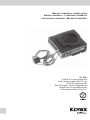
Unità Due Fili per targa audio
Audio entrance panel Due Fili unit
Unité 2Fili platine audio
DueFili Einheit f. Audio-Klingeltableau
Unidad Due Fili para placa audio
Posto externo audio Dois Fios”
Il manuale istruzioni è scaricabile dal sito
www.vimar.com
The instruction manual is downloadable from
the site www.vimar.com
Télécharger le manuel d’instructions sur le
site www.vimar.com
REGOLE D’INSTALLAZIONE
L’installazione deve essere effettuata con
l’osservanza delle disposizioni regolanti l’installazione del materiale elettrico in vigore nel
paese dove i prodotti sono installati.
INSTALLATION RULES
Installation should be carried out observing
current installation regulations for electrical
systems in the country where the products are
installed.
CONSIGNES D’INSTALLATION
L’installation doit etre effectuee en respectant
les dispositions regissant l’installation du materiel electrique en vigueur dans le pays ou se
trouvent les produits.
CONFORMITÀ NORMATIVA
Direttiva EMC
Norme EN 61000-6-1 e EN 61000-6-3.
CONFORMITY
EMC directive
Standards EN 61000-6-1 and EN 61000-6-3.
CONFORMITÉ AUX NORMES
Directive EMC
Normes EN 61000-6-1 et EN 61000-6-3.
INFORMAZIONE AGLI UTENTI AI
SENSI DELLA DIRETTIVA 2002/96
(RAEE)
Al fine di evitare danni all’ambiente e
alla salute umana oltre che di incorrere in sanzioni amministrative, l’apparecchiatura che
riporta questo simbolo dovrà essere smaltita
separatamente dai rifiuti urbani ovvero riconsegnata al distributore all’atto dell’acquisto di
una nuova. La raccolta dell’apparecchiatura
contrassegnata con il simbolo del bidone
barrato dovrà avvenire in conformità alle
istruzioni emanate dagli enti territorialmente
preposti allo smaltimento dei rifiuti. Per maggiori informazioni contattare il numero verde
800-862307.
INFORMATION FOR USERS UNDER
DIRECTIVE 2002/96 (WEEE)
In order to avoid damage to the environment and human health as well as
any administrative sanctions, any appliance
marked with this symbol must be disposed
of separately from municipal waste, that is it
must be reconsigned to the dealer upon purchase of a new one. Appliances marked with
the crossed out wheelie bin symbol must be
collected in accordance with the instructions
issued by the local authorities responsible for
waste disposal.
COMMUNICATION AUX UTILISATEURS CONFORMÉMENT À LA
DIRECTIVE 2002/96 (RAEE)
Pour protéger l’environnement et la
santé des personnes et éviter toute sanction
administrative, l’appareil portant ce symbole
ne devra pas être éliminé avec les ordures
ménagères mais devra être confié au distributeur lors de l’achat d’un nouveau modèle. La
récolte de l’appareil portant le symbole de la
poubelle barrée devra avoir lieu conformément
aux instructions divulguées par les organisms
régionaux préposés à l’élimination des déchets.
Product is according to EC Directive
2004/108/EC and following norms.
Le produit est conforme à la directive
européenne 2004/108/CE et suivantes.
Il prodotto è conforme alla direttiva
europea 2004/108/CE e successive.
Die Bedienungsanleitung ist auf der Website
www.vimar.com zum Download verfügbar
El manual de instrucciones se puede descargar en la página web www.vimar.com
É possível descarregar o manual de instruções no site www.vimar.com
INSTALLATIONSVORSCHRIFTEN
Die Installation hat nach den im Anwendungsland des Produkts geltenden Vorschriften zur
Installation elektrischen Materials zu Erfolgen.
NORMAS DE INSTALACIÓN
La instalacion debe realizarse cumpliendo las
disposiciones en vigor que regulan la instalacion del material electrico en el pais donde se
instalan los produco.
REGRAS DE INSTALAÇÃO
A instalacao deve ser efectuada de acordo
com as disposicoes que regulam a instalacao
de material electrico, vigentes no pais em que
os produtos sao instalados.
NORMKONFORMITÄT
EMC-Richtlinie
Normen EN 61000-6-1 und EN 61000-6-3.
CONFORMIDAD NORMATIVA
Directiva EMC
Normas EN 61000-6-1 y EN 61000-6-3.
CUMPRIMENTO DE REGULAMENTAÇÃO
Directiva EMC
Norma EN 61000-6-1 e EN 61000-6-3.
VERBRAUCHERINFORMATION
GEMÄSS RICHTLINIE 2002/96
(WEEE)
Zum Schutz von Umwelt und Gesundheit, sowie um Bußgelder zu vermeiden,
muss das Gerät mit diesem Symbol getrennt
vom Hausmüll entsorgt oder bei Kauf eines
Neugeräts dem Händler zurückgegeben
werden. Die mit dem Symbol der durchgestrichenen Mülltonne gekennzeichneten Geräte
müssen gemäß den Vorschriften der örtlichen
Behörden, die für die Müllentsorgung zuständig sind, gesammelt warden.
INFORMACIÓN A LOS USUARIOS
DE CONFORMIDAD CON LA DIRECTIVA 2002/96 (RAEE)
Para evitar perjudicar el medio ambiente y la salud de las personas, así como
posibles sanciones administrativas, el aparato
marcado con este símbolo no deberá eliminarse junto con los residuos urbanos y podrá entregarse en la tienda al comprar uno nuevo. La
recogida del aparato marcado con el símbolo
del contendedor de basura tachado deberá
realizarse de conformidad con las instrucciones emitidas por las entidades encargadas de
la eliminación de los residuos a nivel local.
INFORMAÇÃO AOS UTILIZADORES NOS TERMOS DA DIRECTIVA
2002/96 (REEE)
Para evitar danos ao meio ambiente e
à saúde humana, e evitar incorrer em sanções
administrativas, o equipamento que apresenta
este símbolo deverá ser eliminado separatamente dos resíduos urbanos ou entregue ao
distribuidor aquando da aquisição de um novo.
A recolha do equipamento assinalado com
o símbolo do contentor de lixo barrado com
uma cruz deverá ser feita de acordo com as
instruções fornecidas pelas entidades territorialmente previstas para a eliminação de
resíduos.
Das Produkt entspricht den europäischen Richtlinien 2004/108/
EG und Nachfolgenden.
El producto es conforme a la directiva europea 2004/108/CE y
sucesivas.
O produto está conforme a directiva europeia 2004/108/CE e seguintes.
2
PT
ES
DE
FR
EN
IT
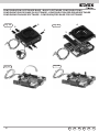
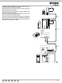
Generalità
General information
L’articolo 6931 è un posto esterno per impianti citofonici
e videocitofonici DUE FILI ELVOX. L’articolo 6931 ha la
possibilità di gestire fino a 200 chiamate e può essere utilizzato
come un posto esterno Master, permettendo la realizzazione
di impianti citofonici e videocitofonici con l’utilizzo di una
telecamera supplementare. Ha la possibilità di coesistere
con targhe elettroniche audio/video in un sistema DUE FILI
ELVOX misto (citofonico/videocitofonico), mediante l’utilizzo di
concentratori art. 692C.
Article 6931 is a speech unit for DUE FILI ELVOX “ELVOX
TWO-WIRE” audio door entry systems. Article 6931 can
manage up to 200 calls and can be used as a Master speech
unit, making it possible to create audio door entry systems. In
addition, it can co-exist with video panels in a mixed DUE FILI
ELVOX “ELVOX TWO-WIRE” system (interphone/monitor), by
using concentrators art. 692C.
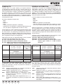
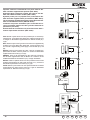
Può essere installato in targhe serie:
-8000
-8100
- Patavium
-3300
- Targhe portalettere (2550/301 e 2550/302)
- 1200 (per piu’ di 2 pulsanti è necessario l’abbinanamento di
una o più placche supplementari con tasti Art. 125x)
Il posto esterno Art. 6931 è totalmente equivalente all’Art. 6930
con la differenza che in caso di collegamento di telecamera
Art. 6570, 657C o di interfaccia per telecamera TVCC Art.
693T, permette una maggiore distanza tra il posto esterno e
la telecamera (vedere schemi di collegamento N. SI559, SI560
per le lunghezze massime dei collegamenti).
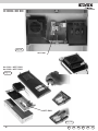
Abbinamento Art. 6931 con telecamere B/N o a colori, o modulo
convertitore per telecamera esterna tipo TVCC.
Art. 6570 Telecamera B/N senza posto esterno
Art. 657C Telecamera a colori senza posto esterno
Art. 693T Modulo convertitore per telecamera esterna (tipo
TVCC), B/N o colori su custodia DIN 4 moduli.
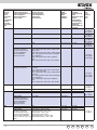
Serie targa
con telecamera interna
art. 6931 + art. 6570
art. 6931 + art. 657C
8000
SI
applicando
art. 8010 + 8020 (per 6570)
art. 8010 + 8T20 (per 657C)
8100
NO
PATAVIUM
NO
3300
NO
2550/301-302
SI
1200
NO
It can be installed in entrance panels series:
-8000
-8100
- Patavium
-3300
- Mail boxes (2550/301 and 2550/302)
- 1200 (for more than 2 push-buttons it is necessary to couple
one or more additional plates with push-buttons type 125x).
Speech unit type 6931 is completely equivalent to type 6930.
The only difference is that, in case of connection of camera
type 6570, 657C or interface for TVCC camera type 693T it
enables a higher distance between the speech unit and the
camera (see wiring diagrams N. SI559, SI560 for the maximum
length of wiring).
Type 6931 can be coupled with B/W or colour cameras, or with
converter module for external camera type CCTV.
Type 6570 B/W camera without speech unit
Type 657C Colour camera without speech unit
Type 693T Converter module for external B/W or colour
camera (type CCTV) in 4 DIN modules
enclosure.
con telecamera esterna
art. 6931 + art.
693T
SI
Series of entrance panels
SI
SI
SI
SI
SI
8100
PATAVIUM
3300
2550/301-302
1200
8000
With internal camera
type 6931 + type 6570
type 6931 + type 657C
YES
by applying
type 8010 + 8020 (for 6570)
type 8010 + 8T20 (for 657C)
NO
NO
NO
YES
NO
With external camera
type 6931 +
type 693T
YES
YES
YES
YES
YES
YES
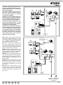
Al posto esterno art. 6931 possono essere collegati i moduli
di espansione (Art. 12TS, 12TS/0, 693P, 8051, 8052, 8053,
8054), per aumentare il numero dei pulsanti di chiamata in
funzione del tipo di targa.
The expansion modules (type 12TS, 12TS/0, 693p, 8051,
8052, 8053, 8054) can be connected to speech unit type 6931
to increase the number of the call push-buttons according to
the type of panel.
12TS
12TS Additional module with 4 call push-buttons to install in
panels series 1200.
12TS/0 Additional module for connecting 8 push-buttons,
applicable also to entrance panels not belonging to
the Elvox series.
693P Addition module with reduced dimensions: 48x70x19
mm (W x H x D), to be applied also to non ELVOX
entrance panels.
8054 (8051, 8052, 8053) additional modules with 4, 1, 2,
3 call push-buttons with plates, for entrance panels
series 8000.
Modulo supplementare con 4 pulsanti di chiamata da
installare su targhe della serie 1200.
12TS/0 Modulo supplementare per il collegamento di 8
pulsanti, applicabile anche su targhe non Elvox.
693P Modulo supplementare di dimensioni ridotte
48x70x19mm (Largh.xAltxProf.), applicabile anche
su targhe non Elvox.
8054
(8051, 8052, 8053) moduli supplementari con 4, 1, 2,
3 pulsanti di chiamata con placche, per targhe serie
8000.
IT
EN
FR
DE
ES
PT
3
GÉNÉRALITÉS
ALLGEMEINES
L’article 6931 est un poste externe pour installations portier
“DUE FILI ELVOX”. L’article 6931 peut gérer jusqu’à 200 appels et peut être utilisé comme poste externe Master, en permettant de réaliser des installations portier. En outre, il peut
être associé à des plaques vidéo dans un système “DUE FILI
ELVOX” mixte (postes/moniteurs) à l’aide de concentrateurs
art. 692C.
Der Artikel 6931 ist eine Türsprechstelle für ELVOX Due Fili
Türsprechanlagen. Der Artikel 6931 kann bis zu 200 Rufe
verwalten und kann als Hauptsprechstelle bei der Installation
von Türsprechanlagen eingesetzt werden. Er kann zudem
unter Verwendung von Konzentratoren (Art. 692C) mit Video-Türsprechstellen in einer gemischten ELVOX Due Fili
Anlage (Torsprech-/Videotorsprechanlage) kombiniert werden.
Il peut être installé dans les plaques de rue série:
- 8000
-8100
- Patavium
-3300
- Plaques boîtes aux lettres (2550/301 et 2550/302)
- 1200 (pour plus de 2 boutons-poussoirs il es nécessaire
d’accoupler une ou plus plaques supplémentaires avec
poussoirs Art. 125x).
Er kann in Klingeltableaus der nachstehenden Baureihen
eingebaut werden:
- 8000
- 8100
- Patavium
- 3300
- Briefkasten (2550/301 und 2550/302)
- 1200 (für mehr als 2 Tasten ist es notwendig, ein oder
mehrere Zusatztableaus nur mit Tasten Art. 125x zu verwenden).
Le portier extérieur Art. 6931 est en tout et pour tour équivalent
à l’Art. 6930 mais en cas de connexion d’une caméra Art. 6570,
657C ou d’une interface pour caméra CCTV Art. 693T, il permet d’avoir une plus grande distance entre le portier extérieur
et la caméra (voir schémas de connexion N. SI559, SI560 pour
les longueurs maximums des connexions).
Accouplement Art. 6931 avec caméras en B/N ou en couleurs,
ou module convertisseur pour caméra externe type TVCC.
Art. 6570Caméra en B/N sans poste externe audio
Art. 657CCaméra en couleurs sans poste externe audio
Art. 693T Module convertisseur pour caméra externe (type
TVCC), en B/N ou en couleurs en boîtier de 4
modules DIN
Plaque de
rue série
Avec caméra interne
Avec caméra externe
art. 6931 + art. 6570
art. 6931 + art. 693T
art. 6931 + art. 657C
OUI
8000
OUI
en appliquant
art. 8010 + 8020 (pour 6570)
art. 8010 + 8T20 (pour 657C)
8100
OUI
NON
PATAVIUM
OUI
NON
3300
OUI
NON
2550/301-302 OUI
OUI
1200
OUI
NON
Die Außensprechstelle Art. 6931 ist absolut gleichwertig mit Art.
6930, mit dem einzigen Unterschied, dass sie bei Anschluss
einer Videokamera Art. 6570, 657C oder einer Schnittstelle
für Videoüberwachungskamera Art. 693T einen größeren Abstand zwischen Außensprechstelle und Videokamera gestattet
(siehe Anschlusspläne Nr. SI559, SI560 für die max. Anschlusslängen).
Kombination des Art. 6931 mit S/W oder Farbkameras, oder mit
Konvertermodul für externe Videokamera .
6570 S/W Kamera ohne Sprechstelle
657C Farbkamera ohne Sprechstelle
693T
Konvertermodul für externe S/W oder Farbkamera
im 4 DIN Modul-Gehäuse.
Klingeltableau
8000
8100
PATAVIUM
3300
2550/301-302
1200
Mit interner Kamera
Mit externer Kamera
Art. 6931 + Art. 6570
Art. 6931 + Art. 693T
Art. 6931 + Art. 657C
JA
JA
Durch Verwendung des
Art. 8010 + 8020 (für 6570)
Art. 8010 + 8T20 (für 657C)
JA
NEIN
JA
NEIN
JA
NEIN
JA
JA
JA
NEIN
Les modules d’expansion (Art. 12TS, 12TS/0, 693P, 8051,
8052, 8053, 8054) peuvent être raccordés au poste externe Art.
An der Sprechstelle Art. 6931 können die Erweiterungsmodule
6931 pour augmenter le nombre de boutons-poussoirs d’appel
(Art. 12TS, 12TS/0, 693P, 8051, 8052, 8053, 8054) angeselon le type de plaque de rue.
schlossen werden um die Ruftastenanzahl in Bezug auf die
Klingeltableauart zu erhöhen.
12TS Module supplémentaire avec 4 boutons-poussoirs
d’appel à installer sur les plaques de rue de la série
12TS Zusatzmodul mit 4 Ruftasten für Klingeltableaus der
1200.
Baureihe 1200.
12TS/0 Module supplémentaire pour le raccordement de 8
12TS/0 Zusatzmodul zum Anschluss von 8 Tasten, auch für
boutons-poussoirs, applicable aussi sur le plaques de
nicht Elvox Klingeltableaus.
rue non ELVOX.
693P Zusatzmodul zum Anschluss von 8 Tasten mit redu693P Module supplémentaire de dimensions réduites:
zierten Abmessungen: 48x70x19 mm (BxHxT), auch
48x70x19 mm (LxHxP), applicable aussi sur les plafür nicht Elvox Klingeltableaus.
ques non ELVOX.
8054 (8051, 8052, 8053) Zusatzmodule mit 4, 1, 2, 3 Rufta8054 (8051, 8052, 8053) modules supplémentaires avec 4,
sten mit Frontblende, für Klingeltableaus der Baureihe
1, 2, 3 boutons-poussoirs d’appel avec dalles, pour
8000.
plaques de rue série 8000.
4
PT
ES
DE
FR
EN
IT
GENERALIDADES
GENERALIDADES
El artículo 6931 es un aparato externo para porteros eléctricos
DOS HILOS ELVOX. El artículo 6931 puede gestionar hasta
200 llamadas y se puede utilizar como aparato externo master
con lo cual permite realizar instalaciones de porteros eléctricos.
También puede instalarse con placas vídeo en un sistema DOS
HILOS ELVOX mixto (teléfonos/monitores), usando concentradores art. 692C.
O artigo 6931 é um posto externo para instalações audio dois
fios ELVOX. O artigo 6931 tem a possibilidade de gerir até
200 chamadas e pode ser utilizado como um posto externo
Master, permitindo a realização de instalações de porteiros
eléctricos. Tem a possibilidade de coexistir com botoneiras
vídeo num sistema dois fios ELVOX misto (telefone / monitor),
através da utilização de concentradores art. 692C.
Puede ser instalado en placas serie:
-8000
-8100
- Patavium
-3300
- Led tarjeta portanombres (2550/301 e 2550/302)
- 1200 (para más de dos pulsadores hay que acoplar una o
más plan chas suplementarias con pulsadores Art. 125x).
Pode ser instalado em botoneiras da série:
-8000
-8100
- Patavium
-3300
- Botoneiras caixas de correio (2550/301 e 2550/302)
- 1200 (para mais do que dois botões tem-se de juntar uma
ou mais placas suplementares con botões Art. 125x).
El aparato externo Art. 6931 es totalmente equivalente al Art.
6930, salvo que en caso de conexión de la cámara Art. 6570,
657C o interfaz para la cámara TVCC Art. 693T, permite una
distancia mayor entre el aparato externo y la cámara (consulte
los esquemas de conexión N. SI559, SI560 para ver la máxima
longitud de las conexiones).
O posto externo Art. 6931 é totalmente equivalente ao Art.
6930 com a diferença de que, em caso de ligação da telecâmara Art. 6570, 657C ou da interface para telecâmara TVCC Art.
693T, permite uma maior distância entre o posto externo e a
telecâmara (ver esquemas de ligação N. SI559, SI560 para os
comprimentos máximos das ligações).
Acoplamiento del Art. 6931 con cámaras en B/N o en color, o
módulo convertidor para cámara externa tipo TVCC.
6570 Cámara en B/N sin aparato externo.
697C Cámara en color sin aparato externo.
693T Módulo convertidor para cámara externa (Tipo
TVCC) en B/N o en color en caja DIN de 4 módulos.
Junção do Art. 6931 com telecâmaras em B/P ou a cores, ou
modulo convertidor para telecâmara externa tipo TVCC.
6570 Telecâmara em B/N sem posto externo.
697C Telecâmara a cores sem posto externo.
693T Módulo convertidor para telecâmara externa do
tipo TVCC, em B/P o a cores em contentor DIN de
4 módulos.
Serie placa
Con cámara interna
art. 6931 + art. 6570
art. 6931 + art. 657C
8000
SI
aplicando
art. 8010 + 8020 (6570)
art. 8010 + 8T20 (657C)
8100
NO
PATAVIUM
NO
3300
NO
2550/301-302 SI
1200
NO
Con cámara externa
art. 6931 + art. 693T
SI
8000
SI
SI
SI
SI
SI
Al aparato externo Art. 6931 se pueden conectar los módulos
de expansión (Art. 12TS, 12TS/0, 693P, 8051, 8052, 8053,
8054) para aumentar el número de pulsadores de llamada en
función del tipo de placa.
12TS Módulo suplementar con 4 pulsadores de llamada
para instalar en placas de la serie 1200.
12TS/0 Módulo suplementar para el conexionado de 8 pulsadores, aplicable también a las placas no Elvox.
693P Módulo suplementar de dimensiones reducidas:
48x70x19 mm (LxHxP), aplicable también a las placas no Elvox.
8054
(8051, 8052, 8053) módulos suplementarios con 4, 1,
2, 3 pulsadores de llamada con planchas para placas
série 8000.
IT
EN
FR
DE
ES
PT
Serie da
botoneira
8100
PATAVIUM
3300
2550/301-302
1200
Com telecâmara interna
art. 6931 + art. 6570
art. 6931 + art. 657C
SIM
aplicando
art. 8010 + 8020 (para 6570)
art. 8010 + 8T20 (para 657C)
NÃO
NÃO
NÃO
SIM
NÃO
Com telecâmara
externa
art. 6931 + art. 693T
SIM
SIM
SIM
SIM
SIM
YES
Ao posto externo podem-se ligar os módulos de expansão (Art.
12TS, 12TS/0, 693P, 8051, 8052, 8053, 8054) para aumentar
o número de botões de chamada em função do tipo de botoneira.
12TS
Módulo suplementar com 4 botões de chamada em
função do tipo de botoneira.
12TS/0 Módulo suplementar para a ligação de 8 botões, aplicável também às botoneiras não Elvox.
693P Módulo suplementar de dimensões reduzidas:
48x70x19 mm (LxHxP) aplicável também às botoneiras não Elvox.
8054
(8051, 8052, 8053) módulos suplementares com 4, 1,
2, 3 botões de chamada com placas, para botoneiras
da série 8000.
5
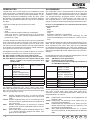
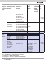
Serie targa
Series of
entrance
panels
Série plaque
de rue
Klingeltableau
Baureihe
Serie placa
Serie da botoneira
Numero pulsanti
Number of push-buttons
Nombre de boutons-poussoirs
Anzahl Klingeltasten
Número de pulsadores
Número botões
Articolo targa
Entrance panel type
Article Plaque de rue
Artikel Klingeltableau
Artículo placa
Artigo botoneira
Cablaggi
Cables
Câblages
Kabel
Cableado
Cablagens
8000
1
88T1
C3.4, C3.6
1
8911
C3.4, C3.6
2
88T2
C3.2, C3.4, C3.6
2
891D
C3.2, C3.4, C3.6
Più di 2 pulsanti
More than 2 push-buttons
Plus de 2 boutons-poussoirs
Mehr als 2 Klingeltasten
Más de 2 pulsadores
Mais do que 2 botões
CN10, C3.3
80PA + 8054 (o 8051, 8052, 8053) + telai, scatole
80PA + 8054 (o 8051, 8052, 8053) + module holder
frames, boxes
80PA + 8054 (o 8051, 8052, 8053) + châssis, boîtiers
80PA + 8054 (oder 8051, 8052, 8053) + Montagerahmen und Gehäuse
80PA + 8054 (o 8051, 8052, 8053) + bastidores,
cajas
80PA + 8054 (o 8051, 8052, 8053) + aros, caixilhos
Più di 2 pulsanti
More than 2 push-buttons
RPF3 + 8054 (o 8051, 8052, 8053) + telai, scatole
CN10
serie 8000
RPF3 + 8054 (o 8051, 8052, 8053) + module holder
frames, boxes series 8000
RPF3 + 8054 (o 8051, 8052, 8053) + châssis, boîtiers
série 8000
RPF3 + 8054 (oder 8051, 8052, 8053) + Montagerahmen und Gehäuse
RPF3 + 8054 (o 8051, 8052, 8053) + bastidores,
cajas
RPF3 + 8054 (o 8051, 8052, 8053) + aros, caixilhos
8100
PATAVIUM
1200
6
Portalampada
sostitutivo
Substitutive lamp
holder
Porte-lampe substitutif Art.
Ersatz-Tableaube-leuchtung Art.
Porta-lámpara sustitutivo Art.
Portalám-pada adicional Art.
Art. R263
Art. R263
Figura
Figure
Figure
Abbildung
Figura
Figura
Fig. 5, pag. 10
Fig. 5, page 10
Abb. 5, Seite 10
Fig. 6, pag. 10
Fig. 6, page 10
Abb. 6, Seite 10
Fig. 5, pag. 10
Fig. 5, page 10
Abb. 5, Seite 10
Fig. 6, pag. 10
Fig. 6, page 10
Abb. 6, Seite 10
Fig. 4B, pag. 9
Fig. 4B, page 9
Abb. 4B, Seite 9
Fig. 4A, pag. 9
Fig. 4A, page 9
Abb. 4A, Seite 9
1
8101
C3.4, C3.6
2
8102
C3.2, C3.4, C3.6
1
2
2101
2102
C3.4, C3.6
C3.2, C3.4, C3.6
Più di 2 pulsanti
More than 2 push-buttons
Plus de 2 boutons-poussoirs
Mehr als 2 Klingeltasten
Más de 2 pulsadores
Mais do que 2 botões
1
2
Più di 2 pulsanti
More than 2 push-buttons
Plus de 2 boutons-poussoirs
1200 mit mehr als 2 Ruftasten
1200 con más de 2 llamadas
1200 com mais do que 2 chamadas
21xx + 693P
C3.6, CN10
1221
1222
1220 con 6931 + 125x con 12TS
1200 (only for 6931) + 125x + 12TS
1220 pour 6931 + 125x + 12TS
1220 mit 6931+ 125x mit 12TS
1220 (sólo para 6931) + 125x con 12TS
1220 (so para Art. 6931) + 125x + 12TS
C3.4, C3.6
C3.2, C3.4, C3.6
C3.6, CN10
PT
Fig. 8, pag. 12
Fig. 8, page 12
Abb. 8, Seite 12
Fig. 9, pag. 12
Fig. 9, page 12
Abb. 9, Seite 12
Art. R264
Art. R264
Art. R264
ES
DE
Fig. 7, pag. 11
Fig. 7, page 11
FR
EN
IT
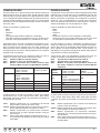
Serie targa
Series of
entrance panels
Série plaque
de rue
Klingeltableau
Baureihe
Serie placa
Serie da botoneira
Numero pulsanti
Number of push-buttons
Nombre de boutons-poussoirs
Anzahl Klingeltasten
Número de pulsadores
Número botões
Articolo targa
Entrance panel type
Article Plaque de rue
Artikel Klingeltableau
Artículo placa
Artigo botoneira
Cablaggi
Cables
Câblages
Kabel
Cableado
Cablagens
3300
1
3301 + scatola serie 3300
3301 + Back box Serie 3300
3301 + boîtier série 3300
3301 + Unterputzkasten Serie 3300
3301 + caja serie 3300
3301 + caixilho da série 3300
3302 + scatola serie 3300
3302 + Back box Serie 3300
3302 + boîtier série 3300
3302 + Unterputzkasten Serie 3300
3302 + caja serie 3300
3302 + caixilho da série 3300
3300 + 3958 + scatola serie 3300
3300 + 3958 + Back box Serie 3300
3300 + 3958 + boîtier série 3300
3300 + 3958 + Unterputzkasten Serie 3300
3300 + 3958 + caja serie 3300
3300 + 3958 + caixilho da série 3300
330X + 39xx + 693P + scatola serie 3300
330X + 39xx + 693P + Back box Serie 3300
3300 + 3958 + boîtier série 3300
3300 + 3958 + Unterputzkasten Serie 3300
3300 + 3958 + caja serie 3300
3300 + 3958 + caixilho da série 3300
2550/301
C3.4, C3.6
Portalampada
sostitutivo
Substitutive lamp
holder
Porte-lampe substitutif Art.
Ersatz-Tableaube-leuchtung Art.
Porta-lámpara
sustitutivo Art.
Portalám-pada
adicional Art.
Art. R261
C3.2, C3.4, C3.6
Art. R261
C3.4, C3.6
Art. R261
2550/302
25V2*
25V2
25V4 o 25V6 o 25V8, 693P
25V4 or 25V6 or 25V8, 693P
25V4 ou 25V6 ou 25V8, 693P
25V4 ooder 25V6 oder 25V8, 693P
25V4 o 25V6 o 25V8, 693P
25V4 ou 25V6 ou 25V8, 693P
25V8, 2508, 2x693P
C3.2, C3.4, C3.6
C3.4, C3.6
C3.2, C3.4, C3.6
C3.6
Art. R261
Art. R264
Art. R264
Art. R264
C3.6, C3.10
Art. R264
2
Più di 2 pulsanti
More than 2 push-buttons Plus
de 2
boutons-poussoirs
Mehr als 2 Klingeltasten
Más de 2 pulsadores
Mais do que 2 botões
2550/301-302
1
2
Casellario postale 1
Cabinet
2
Boîte aux lettres
Fino a 8 pulsanti
collective
Up to 8 push-buttons
Briefkästen
Jusqu’à 8 appels
Buzón
Bis 8 Tasten
Caixa de correio Hasta 8 pulsadores
Até 8 botões
Fino a 16 pulsanti
Up to 16 push-buttons
Jusqu’à 16 appels
Bis 16 Tasten
Hasta 16 pulsadores
Até 16 botões
Fino a 24 pulsanti
Up to 24 push-buttons
Jusqu’à 24 8 appels
Bis 24 Tasten
Hasta 24 pulsadores
Até 24 botões
25V8, 2526, 693P, 2x693P
Figura
Figure
Figure
Abbildung
Figura
Figura
Fig. 11, pag. 13
Fig. 11, page 13
Abb. 11, Seite 13
CN10
C3.6, CN10
CN10 e cablaggi di art. Art. R264
693P e art. 693P/M
CN10 and cable of art.
693P and art. 693P/M
CN10 et câble de art.
693P et art. 693P/M
CN10 und Kabel für Art.
693P und Art. 693P/M
CN10 y cable de art.
693P y art. 693P/M
CN10 e cabo para art.
693P e art. 693P/M
Fig. 10, pag. 13
Fig. 10, page 13
Abb. 10, Seite 13
Fig. 13, pag. 14
Fig. 13, page 14
Abb. 13, Seite 14
Nella configurazione con * rimane 1 pulsante di chiamata inutilizzato
In the configuration with *, 1 call button remains unused
Dans la configuration avec *, il reste 1 bouton d’appel non utilisé
In der Konfiguration mit * bleibt 1 Ruftaste unbenutzt
En la configuración con * se queda sin utilizar un pulsador de llamada
Na configuração com * fica 1 botão de chamada inutilizado
IT
EN
FR
DE
ES
PT
7
Componenti
Components
Composants
Komponenten
Componentes
Componentes
C3.2 - C3.4
Microfono
Microphone
Microfono
Mikrofon
Microfono
Microfone
Distanziale con viti per installazione posto esterno audio Art. 6931
Bracket with fixing screws for speech unit
Étrier avec vis de fixation pour poste externe audio
Halterung mit Befestigungsschrauben für Türsprechstelle.
Soporte con tornillos de fijación para aparato externo audio
Suporte com parafusos de fixação para posto externo audio
Cablaggio per moduli supplementari a pulsanti a cn10
Cable for additionalpush-button modules to cn10
Câblages pour modules à poussoirs cn10
Kabel für Tastenmodul an cn10
Cableado para módulos con pulsadores a cn10
Cablagem para módulos com botões tipo cn10
Cablaggio per attendere-occupato a C3.3 (Due fili di colore: uno rosso e uno nero)
Cable for “Engaged – Please wait” to C3.3 (Two coloured wires: one red and one black)
Câblage pour «Attendre-Occupé » à C3.3 (Deux fils de couleur : un rouge et un noir)
Kabel für „Besetzt – Bitte Warten“ an C3.3 (Zwei farbige Drähte: ein roter und ein schwarzer)
Cableado para “Esperar-Ocupado” a C3.3 (Dos hilos: uno de color rojo y uno negro)
Cablagem para Esperar-Ocupado tipo C3.3 (Dois fios de cor: um vermelho e um preto)
Cablaggio per illuminazione cartellino portanome a c3.6 - Led cartellino (Due fili di colore: uno verde e uno nero)
Cable for name-tag lighting a c3.6 - Name-tag led (Two coloured wires: one green and one black)
Câblages pour éclairage étiquette porte-noms à c3.6 – Led étiquette (Deux fils de couleur : un vert et un noir)
Kabel für Namensschild-beleuchtung an C3.6 – LED für Namensschild (Zwei farbige Drähte: ein grüner und ein schwarzer)
Cableado para iluminación tarjeta portanombres a c3.6 - Led tarjeta portanombres (Dos hilos: uno de color verde y uno negro)
Cablagem para iluminação do cartão portanomes tipo c3.6 - Led cartão (Dois fios de cor: um verde e um preto)
Cablaggi per due pulsanti a c 3.4 - ch1 a c 3.2 - ch2 (Due fili di colore verde)
Cable for two push-buttons to c 3.4 - ch1 to c 3.2 - ch2 (Two coloured green wires)
Câblages pour deux poussoirs à c 3.4 - ch1 à c 3.2 - ch2 (Deux fils de couleur vert)
Kabel für 2 Klingeltasten an c 3.4 - ch1 an c 3.2 - ch2 (Zwei farbige grüner Drähte)
Cableado para dos pulsadores a c 3.4 - ch1 a c 3.2 - ch2 (Dos hilos de color verde)
Cablagens para módulos com botões tipo c 3.4 - ch1 tipo c 3.2 - ch2 (Dois fios de co verde)
8
PT
ES
DE
FR
EN
IT
Connettore per Art. 950C, Art. 692I o Art. 692I/U
Connector for Art. 950C or Art. 692I or Art. 692I/U
Connecteur pour Art. 950C Art. 692I Art. 692I/U
Steckverbinder für Art. 950C oder Art. 692I oder Art. 692I/U
Conector para art. 950C art. 692I o art. 692I/U
Connettore per Art. 950C Art. 692I ou Art. 692I/U
RESET
Alimentazione LED moduli supplementari
LED supply voltage for additional modules
Alimentation Led pour modules supplementaires
Versorgungsspannung für die LEDs der Zusatzmodule
Alimentación Leds de los módulos suplementarios
Alimentação dos Leds dos módulos suplementares
CN9
CN10
c b a
M VL M CA B2B1 S- S+
Morsetti
M Massa VL
Vl Alimentazione LED per moduli supplementari
M Massa CA
CA Comando apriporta (collegare a “M”)
B2 Bus Due Fili
B1 Bus Due Fili
S- Uscita serratura
S+ uscita serratura
C3.1
C3.2
C3.3
C3.4
C3.5
C3.6
Microfono - Microphone
Microphone - Mikrofon
Micrófono - Microfone
CH2
Attendere/occupato - Wait/busy
Attendre/occupé - Warten/Besetzt
Esperar/ocupado - Aguardar/ocupado
CH1
Video - Vidéo - Video - Vídeo - Vídeo
Led cartellino - Internal LED power supply
Led porte-noms - Interne LED-Versorgung
Led cartellino - Led cartão
Terminals
M VL ground
VL Power supply of LEDS for supplementary modules
Mground
CA Door lock command (connect to “M”)
B2 2-wire bus
B1 2-wire bus
S- Lock output
S+ Lock output
Bornes
M Masse VL
VL Alimentation LED pour modules
supplémentaires
MMasse
CA Commande ouvre-porte (relier à “M”)
B2 Bus 2 fils
B1 Bus 2 fils
S- Sortie gâche
Il posto esterno fornisce un picco di corrente The speech unit gives a current peak IT> 1A S+ Sortie gâche
IT> 1A per 10 mS dopo il quale segue una for 10 ms after which there follows a holding
corrente di mantenimento IM= 200mA per current IM= 200ma for the entire duration of
tutta la durata del comando serratura (vedi the lock command (see lock time).
tempo serratura).
Klemmen
Bornes del aparato externo
für 10 mS, auf die ein Haltestrom von 200
mA für die gesamte Dauer der Betätigung
des Türöffners folgt (siehe Aktivierungszeit
Türöffner).
El aparato externo proporciona un pico de
corriente IT>1A durante 10 mS tras el cual
sigue una corriente de mantenimiento IN=
200mA por toda la duración del mando de la
cerradura (véase tiempo cerradura).
M Masa VL
VL Alimentación de leds para módulos
suplementarios
MMasa
CA Mando abrepuertas (conectar a
masa)
B2
B2 Bus 2 hilos
B1
B1 Bus 2 hilos
S-
S- Salida de la cerradura
S+
Die Sprechstelle liefert eine Stromspitze > 1A S+ Salida de la cerradura
M
VL
M
CA
IT
VL minus
LED-Versorgung für Zusatzmodule
minus türöffnersteuerung (an “M” anschliessen)
2-Drahtbus
2-Drahtbus
Ausgang Türöffner
Ausgang Türöffner
EN
FR
DE
ES
PT
Le poste externe fournit un pic de courant
IT> 1A pendant 10 mS après lequel on a
un courant de maintien IM= 200mA pendant
toute la durée de la commande gâche (voir
temps gâche).
Bornes do posto externo
M Massa VL
VL Alimentação led’s para módulos
suplementares
MMassa
CA Comando trinco (ligar a “m”)
B2 Bus 2 fios
B1 Bus 2 fios
S- Saida trinco
S+ Saida trinco
O posto externo fornece um pico de corrente
IT> 1A durante 10 mS após o qual segue
uma corrente de manutenção IM= 200mA
durante toda a duração do comando do
trinco (ver tempo do trinco).
9
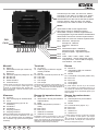
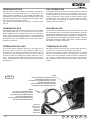
(il fondo non serigrafato è STA.546.003)
VOLUME ESTERNO
SPEECH UNIT VOLUME
2
TERMINAZIONE
BUS
BUS
TERMINATION
A B C
1
AREA PER SERIGRAFIA
7
8 POSTO ESTERNO
FONDO
3
4
5
6
Fig. 1A
PULSANTI
SUPPLEMENTARI
ADDITIONAL
PUSH-BUTTONS
Il disegno è rappresentato in negativo, la versione
definitiva è bianco su fondo nero.
4 3 2 1
Fig. 1B
ID
R
CONNETTORE
PER ART. 950C
CONNECTOR
FOR TYPE 950C
Made in Italy
ART . / TYPE
6931
VOLUME INTERNO
INTERNAL UNIT VOLUME
1 - Microfono / Microphone
2 - CH2
3 - Occupato / Busy
4 - CH1
5 - Video
6 - Alim. LED / LED power
7 - Alim. interna LED / Internal power for LED
8 - Reset
DC 28V INT 6W
TEMPO ATTIVAZIONE
ACTIVATION TIME
VOLUME ESTERNO
SPEECH UNIT VOLUME
7
1
2
3
4
8
5
6
TERMINAZIONE
BUS
BUS
TERMINATION
A B C
PULSANTI
SUPPLEMENTARI
ADDITIONAL
PUSH-BUTTONS
4 3 2 1
ID
Serigrafia per morsetti.
M VL M CA B2 B1 S- S+
44 mm
Regolazioni
Adjustments
Volume esterno
Tempo attivazione posto esterno
Volume interno
Sul retro del posto esterno è riportata una serigrafia per le
regolazioni (vedi Fig. 1A).
External volume
Speech unit activation time
Internal volume
The settings are printed on the back of the speech unit (see
Fig. 1A).
Tempi
Nell’ Art. 6931 alcuni tempi sono regolati tramite trimmer posti
internamente e accessibili esternamente sul retro del posto
esterno tramite un cacciavite (vedi regolazioni posto esterno
Fig. 1B). Il tempo serratura è invece impostato da software.
Times
In Art. 6931 the times are adjusted via the trimmers on the
inside and accessible externally on the back of the speech unit
with the aid of a screwdriver (see speech unit adjustments Fig.
1B).
The lock per
time morsetti.
instead is set via software.
Serigrafia
Tempo di attivazione
Il trimmer TEMPO ATTIVAZIONE regola il tempo di attivazione
del posto esterno per i tre stati nei quali è previsto possa funzionare:
Video camera time
M VL M CA B2 B1 S- S+
The VIDEO CAMERA TIME trimmer adjusts the activation
time of the video camera for the three states in which it can
function: 44 mm
Modo
Chiamata
Conversazione
Autoinserimento
Mimimo
(s)
7,5
30
5
Massimo
(s)
30
120
20
Volumi
Negli Art. 6931 i volumi sono regolati tramite trimmer posti
internamente (Fig. 1B):
VOLUME ESTERNO
VOLUME INTERNO
10
Il volume esterno si regola tramite
il trimmer V.E.
Il volume interno si regola tramite il
trimmer V.I.
Mode
Minimum
(s)
7,5
30
5
Call
Conversation
Self-Start
Maximum
(s)
30
120
20
Volume
In Art. 6931 the volumes are set with trimmers on the inside
(see Fig. 1B):
EXTERNAL VOLUME The external volume is set with the
V.E.
INTERNAL VOLUME The internal volume is set with the
trimmer
V.I. trimmer
PT
ES
DE
FR
EN
IT
Réglages
Einstellungen
TEMPS
Dans l’ Art. 6931, certains temps sont réglés par des trimmers
placés à l’intérieur et accessibles depuis l’extérieur au dos du
poste externe au moyen d’un tournevis (voir réglages poste
externe Fig. 1B). Au contraire, le temps gâche est introduit
par logiciel.
ZEITEN
Beim Art. 6931 werden einige Zeiten von internen Trimmern
geregelt. Diese sind an der Rückseite der Sprechstelle mithilfe eines Schraubenziehers von außen zugänglich (siehe
Einstellungen Türsprechstelle Abb. 1B). Die Türöffnerzeit wird
dagegen über die Software eingestellt.
TEMPS ACTIVATION
Le trimmer TEMPS CAMERA règle de temps d’activation du
poste externe pour les trois états dans lesquels on prévoit son
fonctionnement :
ZEIT VIDEOKAMERA
Der Trimmer ZEIT VIDEOKAMERA dient zur Einstellung der
Einschaltzeit der Videokamera in den drei vorgesehenen Betriebszuständen:
Volume externe
Temps activation poste externe
Volume interne
Au dos du poste externe se trouve une sérigraphie pour les
réglages (voir Fig. 1A)
MODUS
ANRUF
GESPRÄCH
SELBSTEINSCHALTUNG
MINDESTZEIT
(s)
7,5
30
5
HÖCHSTZEIT
(s)
30
120
20
VOLUMES
Dans les Art. 6931, les volumes sont réglés au moyen des
trimmers placés à l’intérieur (VOIR FIG. 1B):
VOLUME EXTÉRIEUR
VOLUME INTÉRIEUR
Le volume extérieur se règle au
moyen du trimmer V.E.
Le volume intérieur se règle au
moyen du trimmer V.I.
Regulaciones
Aktivierungszeit der Türsprechstelle
Lautstärke Innen
Auf der Rückseite sind die Einstellungen aufgedruckt (siehe
Abb. 1A)
MODE
APPEL
CONVERSATION
AUTO-ALLUMAGE
MINIMUM (s)
7,5
30
5
MAXIMUM (s)
30
120
20
LAUTSTÄRKE
Beim Art. 6931 wird die Lautstärke über Trimmer im Inneren
geregelt (SIEHE ABB. 1B):
LAUTSTÄRKE AUSSEN
LAUTSTÄRKE INNEN
Die Aussen-Lautstärke wird mit
dem Trimmer V.E. eingestellt
Die Innen-Lautstärke wird mit
dem Trimmer V.I. eingestellt.
Regulações
Volumen externo
Tiempo de activación del aparato externo
Volumen interno
En la parte posterior del aparato externo hay una serigrafía
para las regulaciones (véase fig. 1A).
TIEMPOS
En el Art. 6931 algunos tiempos se pueden ajustar mediante
los trimmers colocados en el interior del aparato externo y
los que se puede acceder desde la parte posterior utilizando
un destornillador (véase regulaciones del aparato externo fig.
1B). El tiempo de la cerradura se programa desde el software.
Volume externo
Tempo de activação do posto externo
Volume interno
Na parte de trás do posto externo é apresentada uma serigrafia para as regulações (ver Fig. 1A)
TEMPOS
No Art. 6931 os tempos são regulados através de um potenciómetro situados internamente e acessíveis externamente
pela parte de trás do posto externo usando uma chave de
parafusos (ver regulações do posto externo Fig. 1B). O tempo
do trinco é, por sua vez, definido por software.
TIEMPO DE ACTIVACIÓN DE LA CÁMARA
El trimmer TIEMPO DE ACTIVACIÓN DE LA TELECÁMARA
regula el tiempo de activación de la cámara para los tres estados de funcionamiento previstos:
TEMPO DE ACTIVACAO
O potenciómetro TEMPO DE ACTIVACAO regula o tempo de
activação do posto externo para os três estados em que está
previsto o seu funcionamento:
MODO
LLAMADA
CONVERSACIÓN
AUTOENCENDIDO
MÍNIMO (s)
7,5
30
5
MÁXIMO (s)
30
120
20
VOLÚMENES
En los art. 6931, los volúmenes se regulan mediante trimmers
internos (VÉASE FIG. 1B):
Volumen externo
El volumen externo se regula
mediante el trimmer V.E.
El volumen externo se regula
mediante el trimmer V.I.
Volumen interno
IT
EN
FR
DE
ES
PT
MODO
CHAMADA
CONVERSAÇÃO
AUTOINTRODUÇÃO
MÍNIMO (s)
7,5
30
5
MÁXIMO (s)
30
120
20
VOLUMES
Nos Art. 6931 os volumes são regulados através de potenciómetros situados internamente (VER FIG. 1B):
VOLUME EXTERNO
VOLUME INTERNO
O volume externo regula-se com
o potenciómetro V.E.
O volume interno regula-se com
o potenciómetro V.I.
11
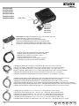
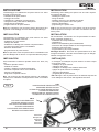
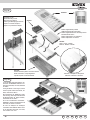
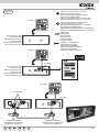
Installazione
Installation
L’assemblaggio e installazione del posto esterno Art. 6931
richiede le seguenti fasi:
- installazione del posto esterno
- cablaggio dei cavetti
- installazione e cablaggio moduli aggiuntivi
- collegamento del posto esterno all’impianto
- assegnazione identificativo
- programmazione del posto esterno
Assembling and installing the speech unit Art. 6931 requires
the following phases:
- installing the speech unit
- wiring the leads
- installing and wiring any additional modules
- connecting the speech unit to the system
- assigning identification
- programming the speech unit
N.B. Non collegare il bus del posto esterno all’impianto fino
a quando i suoi cablaggi non sono stati collegati alla targa.
N.B. Do not connect the bus of the speech unit to the system
until the speech unit wirings have been connected to the entrance panel.
INSTALLATION
INSTALLATION
L’assemblage et l’installation du poste externe Art. 6931
nécessitent les phases suivantes :
- installation du poste externe
- câblage des câbles
- installation et câblage des modules complémentaires
- connexion du poste externe à l’installation
- attribution identification
- programmation du poste externe
N.B. Ne pas relier le bus du poste externe à l’installation tant
que les câblages de ce dernier n’ont pas été reliés à la plaque.
Der Zusammen- und Einbau der Türsprechstelle Art. 6931
läuft in folgenden Phasen ab:
- Installation der Türsprechstelle
- Verkabelung
- Einbau und Verkabelung der Zusatzmodule
- Anschluss der Türsprechstelle an die Türsprechanlage
- Zuweisung des Kenncodes
- Programmierung der Türsprechstelle
Wichtiger Hinweis: Den Bus der Sprechstelle erst an der
Anlage anschließen, nachdem die Verdrahtungen am Klingeltableau durchgeführt wurden.
INSTALAÇÃO
INSTALACIÓN
Para ensamblar e instalar el aparato externo art. 6931, hay
que:
- Instalar el aparato externo.
- Cablear los cables.
- Instalar y cablear los módulos adicionales.
- Conectar el aparato externo a la instalación.
- Asignar el identificador.
- Programar el aparato externo.
A montagem e instalação do posto externo Art. 6931 requer
as seguintes fases:
- instalação do posto externo
- cablagem dos cabos
- instalação e cablagem dos módulos adicionais
- ligação do posto externo à instalação
- atribuição identificativo
- programação do posto externo
N.B. No conecte el bus del aparato externo a la instalación
hasta que los cableados correspondientes estén conectados
a la placa.
N.B. Não ligue o bus do posto externo ao sistema enquanto as
suas cablagens não tiverem sido ligadas à botoneira.
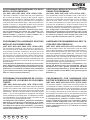
Fig. 2
CN9
ASSEGNAZIONE IDENTIFICATIVO
ASSIGNING IDENTIFICATION
ATTRIBUTION CÔDE IDENTIFICATION
ZUWEISUNG KENNCODE
ASIGNACIÓN DEL IDENTIFICADOR
ATRIBUICÃO DO IDENTIFICATIVO
CN10
PULSANTI SUPPLEMENTARI
ASSIGNING IDENTIFICATION
BOUTONS SUPPLÉMENTAIRES
ZUSATZTASTENMODUL
PULSADORES SUPLEMENTARIOS
BOTÕES SUPLEMENTARES
C
B
A
Microfono
Microphone
Microfono
Mikrofon
Microfono
Microfone
12
PT
ES
DE
FR
EN
IT
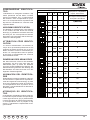
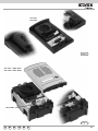
Assegnazione identificativo
L’identificativo è assegnato mediante 4 dip
switch posizionati nel lato basso a sinistra
sopra la morsettiera, (Fig. 2) esternamente
alla scatola e sotto il coperchietto di protezione. La corrispondenza tra la posizione del
dip switch e l’identificativo è contenuta nella
seguente tabella.
Assigning identification
The identifier is assigned with 4 dip switches
on the bottom left side above the terminal
block (Fig. 2), outside the enclosure and under
the safety lid. The correspondence between
the position of the dip switch and the ID is specified in the following table.
ATTRIBUTION CÔDE IDENTIFICATION
Le numéro d’identification est attribué au
moyen de 4 dip-switches positionnés en bas
à gauche au-dessus du bornier (Fig. 2), à l’extérieur du boîtier et sous le couvercle de protection. La correspondance entre la position
du dip-swich et l’identificateur est contenue
dans le tableau suivant.
ZUWEISUNG DES KENNCODES
Der Kenncode wird mit den 4 DIP-Schaltern
zugewiesen, die sich unten links über der
Klemmleiste (Abb. 2) außen am Gehäuse
und unter der Schutzabdeckung befinden. Die
Übereinstimmung zwischen der Stellung des
DIP-Schalters und dem Kenncode ist in der
folgenden Tabelle aufgeführt.
ASIGNACIÓN DEL IDENTIFICADOR
El identificador se asigna mediante 4 dip-switch colocados en la parte inferior izquierda encima de la regleta de conexiones (fig. 2), fuera
de la caja y debajo de la tapa de protección.
La correspondencia entre la posición de los
dip-switch y los identificadores se describe en
la tabla siguiente.
ATRIBUIÇÃO DO IDENTIFICATIVO
O identificativo é atribuído mediante 4 dip switch situados na parte de baixo à esquerda por
cima a régua de bornes, (Fig. 2) externamente
à caixa e por baixo da cobertura de protecção.
A correspondência entre a posição do dip
switch e o idèntificativo é apresentada na seguinte tabela.
IT
EN
FR
DE
ES
PT
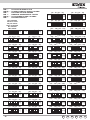
DIP SWITCH
1
2
3
4
Non assegnato - Not assigned
ASSEGNATO
NonNON
assigné
- Nicht zugewiesen
No asignado - Não atribuído
ON
1
2
3
4
2
3
4
2
3
4
2
3
4
2
3
4
2
3
4
2
3
4
2
3
4
2
3
4
2
3
4
2
3
4
2
3
4
2
3
4
2
3
4
2
3
4
2
3
4
ON
1
1 (MASTER)
ON
ON
1
ON
2
ON
3
ON
1
ON
ON
1
ON
4
ON
5
ON
ON
6
ON
ON
7
ON
1
ON
ON
1
ON
ON
1
ON
1
ON
8
ON
9
ON
ON
10
ON
ON
11
ON
ON
12
ON
ON
13
ON
ON
ON
14
ON
ON
ON
15
ON
1
ON
ON
1
ON
1
ON
ON
1
ON
1
ON
ON
1
ON
1
ID targa - Entrance panel ID
TARGA
ID plaque ID
de rue
- Klingeltableau
Id placa - Id da botoneira
ON
13
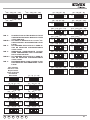
Configurazioni Software base - Basic Software configurations
CONFIGURATIONS DE BASE DU SOFTWARE - KONFIGURATION DER GRUNDSOFTWARE
CONFIGURACIÓN BASE SOFTWARE - CONFIGURAÇÕES BASE POR SOFTWARE
Fig. 3A
1
2
2
2
1
Fig. 3C
14
4
Fig. 3B
3
2
Fig. 3D
PT
ES
DE
FR
EN
IT
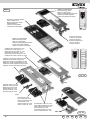
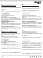
Configurazioni Software base
Basic Software configurations
RIMAPPATURA PULSANTI
Per il posto esterno è possibile rimappare i pulsanti senza utilizzare ausili esterni. Questo viene fatto con la seguente procedura
che viene descritta per un pulsante generico.
• Togliere il coperchio di protezione delle morsettiere facendo
leva sui ganci di chiusura (vedi fig. 3A frecce 1).
• Sollevare la chiusura indicata con 3 (vedi fig. 3B).
• Tenere premuto il pulsante di reset aiutandosi se è il caso
con un cacciavite di plastica. NON UTILIZZARE STRUMENTI
METALLICI CHE POSSONO DANNEGGIARE MECCANICAMENTE IL CIRCUITO ELETTRONICO O REALIZZARE
CORTOCIRCUITI.
• Mantenendo premuto il reset tenere premuto anche il pulsante
di chiamata da riprogrammare.
• Mantenendo premuto il pulsante di chiamata, rilasciare il pulsante di reset.
• Dopo due secondi l’altoparlante emette un tono. Contemporaneamente tutti gli apparecchi a gancio alzato emettono una
scala tritonale.
• Rilasciare il pulsante di chiamata.
• Premere, dall’interno che si intende chiamare con il pulsante,
uno tra i pulsanti serratura, azionamento attuatore (es. luce
scale), F1, F2. Porre attenzione al fatto che se si intende
chiamare un gruppo, questa manovra va eseguita dal capogruppo. Si hanno 30 secondi a disposizione per compiere
questa manovra, dopodiché il posto esterno torna a riposo
emettendo un tono.
• Il posto esterno accetta la programmazione emettendo un
tono.
• Per riportare la programmazione a default, invece di agire
sull’interno premere nuovamente lo stesso pulsante che si
intende programmare.
• Come opzione verificare se l’associazione è corretta premendo il pulsante appena programmato e controllare se viene
chiamato l’interno desiderato.
• Alla fine rimontare il coperchio di protezione.
PUSH-BUTTONS RESET
For the outdoor station it is possible to reset the two push-buttons
CH1 and CH2 without using external helps. This can be done with
the following procedure, described for a generic push-button. It is
applied either to CH1 either to CH2.
- Remove the terminal block protection cover prizing up on the
closing hooks (see fig. 3A, arrow 1).
- Raise the hooks indicated with 1 (arrow upward)
- Hold down the RESET push-button using, if necessary, a plastic screwdriver.
DO NOT USE METALLIC INSTRUMENTS WHICH CAN
DAMAGE MECHANICALLY THE ELECTRONIC CIRCUIT
OR CAUSE SHORT-CIRCUITS.
- Holding down the RESET push-button, keep pressed also the
call push-button to be reprogrammed.
- Hold down the call push-button, release the RESET push-button.
- After two seconds the loudspeaker emits a tone. Simultaneously all the sets with the hook lifted emit a three tone scale.
- Release the call push-button.
- Press, from the internal unit you want to call with the push-button, one of the push-buttons: lock release, actuator activation, stair light, F1, F2. Pay attention that if you want to call a
group, this manoeuvre is to be effected by the leader of the
group. You have 25 seconds to carry out this operation, after
that the outdoor station goes back to the rest mode emitting a
tone.
- The outdoor unit confirms the programming with a tone.
- To return to default programming, instead of acting on the internal unit, press again the push-button you want to program.
- As an option, verify if the association is correct by pressing
the just programmed push-button and control if the desired
internal unit is called.
- At the end fit the protection cover again.
RESET PROGRAMMAZIONI AL VALORE DI FABBRICA
è possibile riportare le programmazioni al valore di fabbrica mediante una semplice procedura.
• Aprire il posto esterno facendo leva sui ganci di chiusura 1 e
2 (vedi Fig. 3A).
• Sollevare la chiusura indicata con 3 e 4 (Fig. 3B).
• Spostare momentaneamente da CN9 il ponticello della terminazione sui terminali 2 e 3 del connettore di programmazione
(vedi Fig. 3C).
• Premere momentaneamente il pulsante di reset RST aiutandosi se è il caso con un cacciavite di plastica. NON
UTILIZZARE STRUMENTI METALLICI CHE POSSONO
DANNEGGIARE MECCANICAMENTE IL CIRCUITO ELETTRONICO O REALIZZARE CORTOCIRCUITI.
• Il posto esterno emette un tono continuo per due secondi.
• Durante l’emissione del tono continuo premere un qualsiasi
pulsante di chiamata. Le programmazioni sono ora azzerate.
Il posto esterno si riavvia da solo.
Alla fine riportare il ponticello sulla posizione originaria di CN9.
RESETTING PROGRAMS TO THE DEFAULT VALUE
It is possible to bring the programs back to the default value with
a straightforward procedure.
• Open the speech unit by levering on the fastener hooks (see
Fig. 4A).
• Raise the fastener labelled 1 (up arrow).
• Raise the fastener labelled 2 (up arrow).
• Momentarily move the jumper of the termination from CN9
onto terminals 2 and 3 of the programming connector (see
Fig. 4B).
• Momentarily press the reset button RST with the aid, if necessary, of a plastic screwdriver.
DO NOT USE ANY METAL INSTRUMENTS THAT CAN
MECHANICALLY DAMAGE THE ELECTRONIC CIRCUIT
OR CREATE SHORT CIRCUITING.
• The speech unit emits a continuous tone for two seconds.
• As the tone is being emitted, press one of the call buttons. The
programs are now reset.
The speech unit restarts by itself. Afterwards put the jumper back
into its original position CN9.
IT
EN
FR
DE
ES
PT
15
CONFIGURATIONS DE BASE DU SOFTWARE
KONFIGURATION DER GRUNDSOFTWARE
RÉORGANISATION DES BOUTONS-POUSSOIRS
Pour le poste externe il est possible de réorganiser les deux boutons-poussoirs CH1 et CH2 sans l’emploi de secours externes.
Cela est fait avec la procédure suivante, décrite pour le poussoir
générique. Elle peut être appliquée soit à CH1 soit à CH2.
- Enlever le couvercle de protection du bornier en faisant force
avec un levier sur les crochets de fermeture (Voir fig. 3A,
flèches 1).
- Soulever la fermeture indiquée avec 1 (flèche vers le haut).
- Maintenir enfoncé le bouton-poussoir de reset en s’aidant, si
nécessaire, avec un tournevis de plastique.
NE PAS UTILISER D’INSTRUMENTS MÉTALLIQUES QUI
PEUVENT ENDOMMAGER MÉCANIQUEMENT LE CIRCUIT ÉLECTRONIQUE OU PROVOQUER DES COURTS-CIRCUITS.
- En maintenant enfoncé le bouton-poussoir de RESET, maintenir enfoncé même le bouton-poussoir d’appel à programmer.
- Maintenir enfoncé le bouton-poussoir d’appel et relâcher le
bouton-poussoir de RESET.
- Après deux secondes le haut-parleur émet un ton. Simultanément tous les appareils avec le crochet levé émettent une
échelle tritonale.
- Relâcher le bouton-poussoir d’appel.
- Appuyer, depuis le poste interne qu’on veut appeler avec le
bouton-poussoir, un parmi les boutons-poussoirs : gâche, activation actionneur, (ex. lumière escalier), F1, F2. Faire attention que si l’on veut appeler un groupe, cette manoeuvre doit
être effectuée par le chef du groupe. Il y a 25 secondes pour
effectuer cette manoeuvre, après lesquels le poste externe retourne à sa position de repos en émettant un ton.
- Le poste externe confirme la programmation avec un ton.
- Pour rétablir les valeurs de programmation par défaut, au
lieu d’agir sur le poste appuyer à nouveau sur le même bouton-poussoir qu’on veut programmer.
- Comme option vérifier si l’association est correcte en appuyant
sur le bouton-poussoir qu’on vient de programmer et contrôler
si l’on appelle le poste désiré.
- À la fin remonter le couvercle de protection.
KLINGELTASTEN RESET
Für die Türsprechstelle ist es möglich, einen Reset für die zwei
Tasten CH1 und CH2 ohne Hilfsmittel durchzuführen. Das kann
mit der folgenden Prozedur ausgeführt werden. Diese wird sowohl
für die Taste CH1 als auch für Taste CH2 verwendet.
- Die Schutzabdeckung der Klemmleiste durch Anheben der
Verschlusshaken entfernen (Siehe Abb. 3A, Pfeil 1)
- Die Reset-Taste drücken und gedrückt halten. Im Bedarfsfall
einen Plastikschraubenzieher verwenden. KEINE METALLWERKZEUGE VERWENDEN, DA DIESE DEN ELEKTRONISCHEN SCHALTKREIS BESCHÄDIGEN ODER
KURZSCHLÜSSE VERURSACHEN KÖNNEN.
- Die Reset-Taste und auch die zu programmierende Ruftaste
gedrückt halten.
- Die Ruftaste gedrückt halten und die Reset-Taste loslassen.
- Nach zwei Sekunden gibt der Lautsprecher einen Ton ab.
Gleichzeitig geben alle Innensprechstellen mit abgehobenem
Handset einen 3-Klangton ab.
- Die Ruftaste loslassen.
- An der mit dem Klingeltaster zu rufenden Innensprechstelle
eine der folgenden Tasten drücken: Türoffner, Zusatzfunktion,
Treppenhauslicht, F1 oder F2. Beachten Sie, dass wenn eine
Gruppe angerufen werden soll, dieser Vorgang vom Hauptapparat vorgenommen wird. Man hat 25 Sekunden Zeit um
diesen Vorgang durchzuführen, dann geht die Türsprechstelle
in den Ruhezustand zurück und gibt einen Einzelton ab.
- Die Türsprechstelle bestätigt die Programmierung mit einem
Ton.
- Um die Programmierung auf den Default-Wert zurückzusetzen,
dieselbe zu programmierende Klingeltaste wieder drücken.
- Optional überprüfen Sie durch Drücken der soeben programmierten Taste, ob die Zuweisung korrekt ist, und kontrollieren
Sie ob die gewünschte Innensprechstelle angerufen wird.
- Zum Schluss die Schutzabdeckung wieder aufsetzen.
RAZ PROGRAMMATION À LA VALEUR D’USINE
Il est possible de remettre les programmations à la valeur d’usine
au moyen d’une simple procédure.
• Ouvrir le poste externe en faisant levier sur les crochets de
fermeture (voir Fig. 4A).
• Soulever la fermeture indiquée avec 1 (flèche vers le haut).
• Soulever la fermeture indiquée avec 2 (flèche vers le haut).
• Déplacer momentanément de la position d’origine CN9 le pontet de la terminaison sur les terminaux 2 et 3 du connecteur de
programmation (voir Fig. 4B).
• Appuyer momentanément sur le bouton de raz RST en utilisant, si besoin est, un tournevis en plastique.
NE PAS UTILISER D’INSTRUMENTS MÉTALLIQUES POUVANT ENDOMMAGER MÉCANIQUEMENT LE CIRCUIT ÉLECTRONIQUE ET PROVOQUER DES COURTS-CIRCUITS.
• Le poste externe émet un ton continu pendant deux secondes.
• Durant l’émission du ton continu, appuyer sur un bouton quelconque d’appel. Les programmations sont mises à zéro. Le
poste externe se met en marche tout seul.
A la fin, remettre le pontet sur la position d’origine CN9.
16
WIEDERHERSTELLUNG DER WERKSEITIGEN STANDARDKONFIGURATION
Die werkseitige Standardprogrammierung kann auf einfache
Weise wieder hergestellt werden.
- Die Türsprechstelle öffnen; dazu die Verschlusshaken entriegeln (siehe Abb. 4A).
- Den mit 1 gekennzeichneten Verschluss anheben (Nach-Oben-Pfeil).
- Den mit 2 gekennzeichneten Verschluss anheben (Nach-Oben-Pfeil).
- Die Brücke des Busabschluss vorübergehend von CN9 auf die
Pins 2 und 3 des Programmiersteckers stecken (siehe Abb.
4B).
- Die Reset-Taste RST drücken; ggf. dazu einen Kunststoffschraubenzieher verwenden. KEINE METALLWERKZEUGE BENUTZEN, DA DIESE
DEN ELEKTRONISCHEN SCHALTKREIS BESCHÄDIGEN
ODER KURZSCHLÜSSE AUSLÖSEN KÖNNEN.
- Die Türsprechstelle erzeugt einen zwei Sekunden langen Signalton.
- Während der Dauer des Signaltons eine beliebige Ruftaste
drücken. Alle Programmierungen sind jetzt gelöscht. Die Türsprechstelle schaltet sich selbstständig wieder ein.
Zum Abschluss die Brücke wieder in die Ausgangsstellung auf
CN9 bringen.
PT
ES
DE
FR
EN
IT
CONFIGURACIÓN BASE SOFTWARE
CONFIGURAÇÕES BASE POR SOFTWARE
REORGANIZACIÓN DE LOS PULSADORES
Para el aparato externo es posible reconfigurar los dos pulsadores
CH1 y CH2 sin utilizar auxilios externos. Esto se hace con el procedimiento siguiente, que viene descrito para un pulsador genérico. Se
aplica sea a CH1 que a CH2.
- Quitar la tapa de protección de las regletas de de conexionado
haciendo palanca sobre los ganchos de cierre (ver fig. 3A, flecha
1).
- Levantar el cierre indicado con 1 (flecha hacia arriba).
- Mantener presionado el pulsador de reset ayudándose, si necesario, con un destornillador. NO UTILIZAR INSTRUMENTOS
METÁLICOS, PUES PUEDEN DA—AR MECÁNICAMENTE EL
CIRCUITO ELECTRÓNICO O REALIZAR CORTOCIRCUITOS.
- Mentenendo presionado el pulsador de reset , mantener presionado también el pulsador de llamada para reprogramar.
- Mantener presionado el pulsador de llamada, soltar el pulsador de
reset.
- Después de dos segundos, el altavoz emite un tono. Simultáneamente todos los apartos com gancho levantado emiten una
escala tritonal.
- Soltar el pulsador de llamada.
- Presionar, desde el aparato interno que se quiere llamar con el
pulsador, uno de los pulsadores cerradura, activación actuador,
luz escaleras, F1, F2. Prestar atención al hecho de que si se entiende llamar un grupo, esta maniobra debe ser efectuada por el
jefe del grupo. Tienen 25 segundos para efectuar esta maniobra,
depués de los cuales el aparato externo vuelve al estado de reposo emitiendo un tono.
- El aparato externo acepta la programación emitiendo un tono.
- Para restablecer la programación a los valores por defeito (default), en vez de actuar en el aparato interno presionar otra vez el
mismo pulsador (que se quiere programar).
- Como opción, verificar si la asociación es correcta presionando
el pulsador recién programado y controlar si se llama el aparato
interno deseado.
- Al final remontar la tapa de protección.
N.B. LA PROGRAMACIÓN NO PUEDE SER EFECTUADA
SOBRE UN APARATO EXTERNO MASTER, PUES NO HAY
NECESIDAD DE RECONFIGURAR LOS PULSADORES DE UN
APARATO EXTERNO MASTER.
RECONFIGURAÇÃO DOS BOTÕES
Para o posto externo é possível reconfigurar os dois botões
CH1 e CH2 sem utilizar auxílios externos. Isto é feito através do
seguinte procedimento que é descrito para um botão genérico.
Tanto se aplica a CH1 como a CH2.
• Retirar a cobertura de protecção da réguade ligaçao usando
os ganchos de fecho (ver fig. 3A setas 1).
• Levantar o fecho indicado com 1 (seta para cima)
• Manter pressionado o botão de Reset utilizando, se necessário, uma chave de parafusos de plástico. NÃO UTILIZAR
INSTRUMENTOS METÁLICOS DADO QUE PODEM DANIFICAR MECANICAMENTE O CIRCUITO ELECTRÓNICO OU PROVOCAR CURTO-CIRCUITOS.
• Mantendo pressionado o botão de Reset, manter também
pressionado o botão de chamada a reprogramar.
• Mantendo pressionado o botão de chamada, libertar o botão
de reset.
• Decorridos dois segundos o altifalante emite um toque. Simultaneamente todos os aparelhos com o gancho levantado
emitem uma escala tritonal.
• Libertar o botão de chamada.
• Premir, do aparelho interno que se pretende chamar com
o botão, um de entre os botões do trinco, accionamento do
actuador (ex. luz das escadas), F1, F2. Prestar atenção ao
facto de que se se pretende chamar um grupo, esta manobra
é executado pelo aparelho definido como principal (Master).
O tempo disponível para completar esta manobra é de 25
segundos, após o que o posto externo volta para o estado
de repouso, emitindo um toque.
• O posto externo aceita a programação emitindo um toque.
• Para repor a programação definida de fábrica (por defeito),
em vez de actuar no aparelho interno premir novamente o
mesmo botão que se pretende programar.
• Como opção, verificar se a associação está correcta pressionando o botão programado e controlar se foi chamado o
aparelho interno pretendido.
• No final recolocar a cobertura de protecção.
RESTABLECIMIENTO DE LAS CONFIGURACIONES SEGÚN
LOS VALORES DE FÁBRICA
Es posible restablecer las configuraciones según los valores de fábrica mediante un procedimiento sencillo.
• Abrir el aparato externo haciendo palanca en los ganchos de
cierre (véase fig. 4A).
• Levantar el cierre indicado con 1 (flecha arriba).
• Levantar el cierre indicado con 2 (flecha arriba).
• Desplazar momentáneamente el puente de la terminación desde
CN9 hasta los terminales 2 y 3 del conector de programación
(véase fig. 4B).
• Accionar momentáneamente el pulsador de restablecimiento RST
con la ayuda de un destornillador de plástico si es necesario. NO
UTILIZAR HERRAMIENTAS METÁLICAS YA QUE PUEDEN
DA—AR MECÁNICAMENTE EL CIRCUITO ELECTRÓNICO O
PROVOCAR CORTOCIRCUITOS.
• El aparato externo emite un tono continuo durante dos segundos.
• Durante la emisión del tono continuo, pulsar cualquier pulsador
de llamada. Entonces, las configuraciones están restablecidas.
El aparato externo se reactiva por sí solo.
Al final, poner el puente en la posición original de CN9.
IT
EN
FR
DE
ES
PT
RESET DAS PROGRAMAÇÕES PARA OS VALORES DE
FÁBRICA
é possível repor as programações para os valores definidos
pela fábrica mediante um simples procedimento.
• Abrir o posto externo através dos ganchos de fecho (ver Fig.
4A).
• Levantar o fecho indicado como 1 (seta para cima).
• Levantar o fecho indicado como 2 (seta para cima).
• Transferir, momentaneamente, de CN9 a ponte da terminação para os terminais 2 e 3 do conector de programação
(ver Fig. 4B).
• Premir, momentaneamente, o botão de Reset RST utilizando, se necessário, uma chave de parafusos de plástico.
NÃO UTILIZAR INSTRUMENTOS METÁLICOS DADO
QUE PODEM DANIFICAR MECANICAMENTE O CIRCUITO ELECTRÓNICO OU PROVOCAR CURTO-CIRCUITOS.
• O posto externo emite um toque contínuo durante dois segundos.
• Durante a emissão do toque contínuo premir um qualquer
botão de chamada. Desta forma, as programações são anuladas. O posto externo reinicia-sea sozinho.
No final recolocar a ponte na posição original de CN9.
17
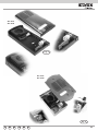
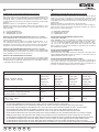
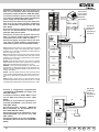
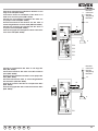
Terminazione Bus
Bus termination
Nel lato basso a sinistra sopra la morsettiera, è presente il
connettore a 3 posizioni CN9 (Fig. 2). Un ponticello in una
delle 3 posizioni possibili (A, B, C), permette di terminare correttamente il bus per quanto riguarda il segnale video in caso
di impianti misti (citofonici e videocitofonici). Provare la condizione che permette la miglior visione.
Se l’impianto è esclusivamente citofonico, inserirlo in posizione A.
On the bottom left side, above the terminal block, there is the
3-position connector CN9 (Fig. 2). A jumper in one of the 3
possible positions (A, B, C) enables terminating the bus correctly as regards the video signal for mixed systems (audio
and video door entry systems). Try out the condition providing
the best vision. If the system is solely an audio door entry
system, insert it in position A.
TERMINAISON BUS
BUSABSCHLUSS
En bas à gauche au-dessus du bornier se trouve le connecteur
à 3 positions CN9 (Fig. 2). Un pontet dans l’une des 3 positions possibles (A, B, C) permet de terminer correctement le
bus en ce qui concerne le signal vidéo, en cas d’installations
mixtes (poste s et portiers vidéo). Essayer la condition qui offre
la meilleure vision. Si l’installation est exclusivement poste ,
l’insérer en position A.
Auf der Klemmenleiste ist unten links ein Steckverbinder CN9
mit 3 Positionen (Abb. 2) angeordnet. Eine Brücke in einer der
drei möglichen Stellungen (A, B, C) erlaubt, den korrekten Busabschluss für das Video-Signal in gemischten Anlagen (Türsprech-/Videotürsprechanlagen) herzustellen. Durch Versuche
das beste Videobild ermitteln. Bei reinen Türsprechanlagen
den Stecker in Position A einfügen.
TERMINACIÓN DEL BUS
TERMINAÇÃO DO BUS
En la parte inferior izquierda, encima de la regleta de conexiones, está el conector de tres posiciones CN9 (fig. 2).
Un puente en una de las tres posiciones posibles (A, B y C)
permite terminar correctamente el bus por lo que se refiere a
la señal de vídeo en instalaciones mixtas (teléfonos y monitores). Realizar pruebas para obtener la mejor condición de
visión. Si la instalación es sólo de porteros eléctricos, poner
el puente en A.
Na parte de baixo à esquerda por cima da régua de bornes,
encontra-se o conector com 3 posições CN9 (Fig. 2).
Uma ponte numa das 3 posições possíveis (A, B, C), permite
terminar correctamente o bus no que diz respeito ao sinal de
vídeo no caso de instalações mistas (porteiros e videoporteiros). Testar a condição que permite o melhor visionamento.
Se a instalação for exclusivamente de audio, inserí-la na posição A.
Fig. 2
CN9
ASSEGNAZIONE IDENTIFICATIVO
ASSIGNING IDENTIFICATION
ATTRIBUTION CÔDE IDENTIFICATION
ZUWEISUNG KENNCODE
ASIGNACIÓN DEL IDENTIFICADOR
ATRIBUICÃO DO IDENTIFICATIVO
CN10
PULSANTI SUPPLEMENTARI
ASSIGNING IDENTIFICATION
BOUTONS SUPPLÉMENTAIRES
ZUSATZTASTENMODUL
PULSADORES SUPLEMENTARIOS
BOTÕES SUPLEMENTARES
C
B
A
Microfono
Microphone
Microfono
Mikrofon
Microfono
Microfone
18
PT
ES
DE
FR
EN
IT
Programmazione hardware pulsanti
moduli supplementari
Additional module push-button hardware programming
I dip-switch modificano il codice fisico del primo pulsante in
alto a destra del modulo, mentre gli altri pulsanti vengono
associati in modo consecutivo dall’alto al basso, da destra a
sinistra (vedi Tab 1 e Tab 2). è importante non sovrapporre i
codici dei pulsanti nella stessa targa. L’utilizzo dei moduli con
pulsanti in singola o in doppia fila richiede che il parametro
“Pulsanti singoli/doppi” sia programmato in modo congruo in
funzione del tipo di moduli (vedi programmazione).
La configurazione del parametro “pulsanti singoli” determina la numerazione dei pulsanti. Se il parametro “pulsanti singoli” è settato a 2 o 3 considerare i valori tra
parentesi quadre [ ], invece se il valore è settato a 0 o 1
considerare i valori tra parentesi graffe { }.
The dip-switches modify the hardware code of the first pushbutton at the top right of the module, while the other pushbuttons are associated consecutively from top to bottom,
right to left (see Tables 1 and 2). Take care not to overlap
the codes of pushbuttons on the same panel. When using the
modules with pushbuttons in single or double columns the
parameter “Single/Double pushbuttons” must be programmed
according to the type of module (see programming).
The configuration of parameter “single push-buttons”
determines the numbering of push-buttons. If the “single
push-buttons” parameter is set to 2 or 3 take into account
the values in [ ] bracket, on the contrary if the value is set
to 0 or 1 take into account the values in { } bracket.
PROGRAMMATION hardware BOUTONS
MODULES SUPPLÉMENTAIRES
HARDWARE-PROGRAMMIERUNG DER TASTEN DER ZUSATZMODULE
Les dip-switches modifient le code physique du premier bouton en haut à droite du module alors que les autres boutons
sont associés de manière consécutive, de haut en bas et de
droite à gauche (voir Tab 1 et Tab 2). Il est important de ne
pas superposer les codes des boutons dans la même plaque.
Pour l’emploi des modules avec boutons à une ou deux rangées, il faut que le paramètre “Boutons simples/doubles” soit
programmé correctement en fonction du type de modules (voir
programmation).
La configuration du paramètre “boutons-poussoirs individuels” détermine la numérotation des boutons-poussoirs.
Si le paramètre « boutons-poussoirs individuels » est programmé à 2 ou 3 considérer les valeurs entre parenthèses
[ ], au contraire si les valeurs sont réglées à 0 ou 1 considérer les valeurs entre parenthèses { }.
Die DIP-Schalter ändern den physischen Code der ersten
oben rechts angeordneten Taste des Moduls, während die anderen Tasten nacheinander von oben nach unten, von rechts
nach links zugewiesen werden (siehe Tab. 1 und Tab. 2). Die
Codes der Tasten desselben Klingeltableaus dürfen sich nicht
überschneiden. Bei Verwendung der Module mit ein- oder
zweireihig angeordneten Tasten muss der Parameter “Ein-/
Zweireihige Tasten” je nach Art der Module entsprechend programmiert werden (siehe Programmierung).
Die Konfiguration des Parameters « Einzeltasten » bestimmt die Nummerierung der Klingeltasten. Wird der
Parameter auf 2 oder 3 gesetzt, beachten Sie die Werte
in den viereckigen Klammern [ ], wird der Wert auf 0 oder
1 gesetzt, beachten Sie die Werte in den geschwungenen
Klammern { }.
PROGRAMACIÓN HARDWARE DE LOS PULSADORES DE LOS MÓDULOS SUPLEMENTARIOS
PROGRAMAÇÃO POR HARDWARE DOS
BOTÕES DOS MÓDULOS SUPLEMENTARES
(Art. 8051, 8052, 8053, 8054, 12TS, 12TS/0, 639P)
(ART. 8051, 8052, 8053, 8054, 12TS, 12TS/0, 639P)
(ART. 8051, 8052, 8053, 8054, 12TS, 12TS/0, 639P)
Los dip-switchs modifican el código físico del primer pulsador
superior de la derecha del módulo mientras que los demás
pulsadores se asocian de manera consecutiva, desde arriba
hasta abajo y desde la derecha hasta la izquierda (véanse
tablas 1 y 2). Es muy importante no sobreponer los códigos
de los pulsadores en la misma placa. El parámetro “Pulsadores únicos/dobles” se ha programar según si el módulo es de
una columna o dos (véase programación).
La configuration del parámetro „pulsadores individuales“
determina la numeración de los pulsadores. Si el parámetro “pulsadores individuales” está programado con 2 o
3 condiderar los valores entre paréntesis [ ], al contrario,
si el parámetro está programado con 0 o 1 considerar los
valores entre paréntesis { }.
IT
EN
FR
DE
ES
PT
(Art. 8051, 8052, 8053, 8054, 12TS, 12TS/0, 639P)
(ART. 8051, 8052, 8053, 8054, 12TS, 12TS/0, 639P)
(ART. 8051, 8052, 8053, 8054, 12TS, 12TS/0, 639P)
Os dip-switch alteram o código físico do primeiro botão em
cima à direita do módulo, enquanto que os outros botões são
associados, consecutivamente, de cima para baixo, da direita
para a esquerda (ver Tab 1 e Tab 2). é importante não sobrepor os códigos dos botões na mesma botoneira. A utilização
dos módulos com botões numa ou em duas filas requer que
o parâmetro “Botões singoli/doppi” esteja programado de
acordo com o tipo de módulos (ver programação).
A configuração do parâmetro “botões simples” determina a numeração dos botões. Se o parâmetro “botões
simples” estiver configurado com 2 ou 3 considerar os
valores entre parêntesis rectos [ ], por sua vez se o valor
estiver configurado com 0 ou 1 considerar os valores
entre chavetas { }.
19
2
3
2
3
1
2
3
21 32
3
1
2
3
1
2
3
1
21 32
3
1
2
ON
1
21 32
3
1
2
3
1
2
3
1
21 32
3
3
1
3
1
2
3
1
2
3
[ 97 ... 100 ] {99 ... 102}
ON
4
8
16
1
2
2
3
1
2
3
ON
3
1
ON ON
ON
2
3
1
2
3
1
ON
21 32
32
64
128
32
64
128
21 32
32
64
128
32
64
4
128
8
16
4
8
16
1
3
1
21 32
ON
3
1
1
3
ON ON
ON
2
3
1
2
3
1
ON ON
1
2
3
1
21 32
ON
ON
3
1
2
1
3
2
3
ON
21 32
3
1
ON ON
2
3
1
2
3
ON
21 32
3
1
2
3
[141 ...[125
] {147
150}... 134}
] {143
146}... 130} [145 ...[129
144 ...
148 ...
128 ]...{127
132 ]...{131
1
ON ON
2
3
1
21 32
ON
ON
3
1
2
1
3
ON ON
2
3
1
ON
21 32
3
1
2
3
[ 29 ... 32
{31
[ 13] ...
{15 ... 18}
16...] 34}
] {151
154}... 138} [153 ...[ 137
] {155
157}... 142}
152...
156 ...
140 ]...{139
136 ]...{135
[ 33 ... 36
{3520...] 38}
[ 17] ...
{19 ... 22} [ 149 ...[133
ON
ON
21 32
3
1
2
3
1
ON ON
2
3
1
21 32
ON
ON
3
1
2
3
[ 37 ... [40
{39
42} ... 26}
21] ...
24...] {23
[ 41 ... [44
] {27
46}... 30}
25] ...{43
28...
ON
ON
1
2
3
1
21 32
3
ON ON
32
64
128
32
64
1284
8
16
4
8
16
4
8
16
4
8
16
ON
1
2
3
1
2
3
1
21 32
3
1
2
3
1
21 32
ON
ON
3
1
2
1
3
ON ON
2
3
1
ON
21 32
3
1
2
3
[157 ...[141
166}... 150}
] {159
162}... 146} [ 161 ...[145
160 ...
164 ]...{163
148 ]...{147
144 ]...{143
ON
ON
3
ON ON
2
ON ON
32
64
128
32
64
1284
8
16
4
8
16
ON ON
1
32
64
128
32
64
128
1
1
2
3
1
21 32
ON
ON
3
1
2
1
3
ON ON
2
3
1
ON
21 32
3
32
64
128
32
64
128
3
32
64
128
32
64
1284
8
16
4
8
16
2
32
64
128
32
64
1284
8
16
4
8
16
1
32
64
128
32
64
1284
8
16
4
8
16
4
8
16
4
8
16
ON
32
64
128
32
64
1284
8
16
4
8
16
ON ON
1
2
3
[ 45 ... [48
50} ... 34}
29] ...{47
32...] {31
170}... 154} [169 ...[153
] {171
174}... 157}
168 ]...{167
172 ...
156 ]...{155
152 ]...{151
[ 49 ... [52
54} ... 38} [165 ...[ 149
33] ...{51
36...] {35
ON
ON
3
1
21 32
3
1
2
3
1
2
3
1
21 32
3
ON ON
1
2
3
1
2
3
1
21 32
ON
ON
3
ON ON
1
2
1
3
2
3
1
ON
21 32
3
32
64
128
32
64
128
2
ON
ON
32
64
128
32
64
1284
8
16
4
8
16
1
ON ON
32
64
128
32
64
1284
8
16
4
8
16
4
8
16
4
8
16
ON
32
64
128
32
64
1284
8
16
4
8
16
ON ON
1
2
3
[ 53 ... [56
{55
{39 ... 42}
37] ...
40...] 57}
[
] {175
178}... 162} [ 177 ...[ 161
182}... 166}
176 ...
180 ]... {179
164 ]...{163
160 ]...{159
[ 57 ... [60
{59
{43 ... 46} 173 ...[157
41] ...
44...] 62}
ON
ON
21 32
ON
3
1
2
3
1
ON ON
2
3
1
21 32
ON
ON
3
1
2
3
1
ON ON
2
3
1
21 32
ON
ON
3
1
2
1
3
ON ON
2
3
1
ON
21 32
3
32
64
128
32
64
128
1
32
64
128
32
64
1284
8
16
4
8
16
3
32
64
128
32
64
1284
8
16
4
8
16
2
32
64
128
32
64
1284
8
16
4
8
16
ON ON
4
8
16
4
8
16
1
1
2
3
[ 61 ... [64
{63
{47 ... 50}
45] ...
48...] 66}
[
] {183
186}... 170} [ 185 ...[169
190}... 174}
184 ...
188 ]...{187
172 ]...{171
168 ]...{167
[ 65 ... [68
{67
{51 ... 54} 181 ...[165
49] ...
52...] 70}
ON
ON
3
1
21 32
3
1
2
3
1
ON ON
2
3
1
21 32
ON
ON
3
1
2
3
1
ON ON
2
3
1
21 32
ON
ON
3
1
2
1
3
ON ON
2
3
1
ON
21 32
3
32
64
128
32
64
128
2
32
64
128
32
64
1284
8
16
4
8
16
1
32
64
128
32
64
1284
8
16
4
8
16
4
8
16
4
8
16
ON
32
64
128
32
64
1284
8
16
4
8
16
ON ON
1
2
3
[ 69 ... [72
{55 ... 57}
{71
53] ...
56...] 74}
] {191
194}... 178} [ 193 ...[ 177
198}... 182}
192 ...
196 ]...{195
180 ]...{179
176 ]...{175
[ 73 ... [76
{59 ... 62} [189 ...[ 173
{75
57] ...
60...] 78}
ON
ON
1
2
3
1
ON ON
2
3
1
21 32
ON
ON
3
1
2
3
1
ON ON
2
3
1
21 32
ON
ON
3
1
2
1
3
[ 77 ... [80
{79
{63 ... 66}
61]...
64...] 82}
200}... 186}
200 ]...{199
184 ]...{183
[ 81 ... [84
{83
{67 ... 70} [ 197 ...[ 181
65]...
68...] 86}
ON
ON
21 32
3
1
2
3
[ 85 ... 88[ 69
] {87
... 90}
] {71 ... 74}
... 72
ON ON
ON
2
3
1
21 32
3
1
2
3
[ 89 ... 92[ 73
... ]94}
] {91
{75 ... 78}
... 76
ON
32
64
128
32
64
284
8
16
4
8
16
4
8
16
4
8
16
ON
1
ON ON
1
2
3
1
21 32
3
1
ON
ON
ON
21 32
2
3
PT
3
1
2
3
[ 185 ... 188 ] {187 ... 190}
1
[189 ... 192 ] {191 ... 194}
ON
1
ON
32
64
128
1
3
ON
32
64
128
32
64
128
3
ON ON
4
8
16
2
ON
ON
32
64
128
32
64
1284
8
16
4
8
16
1
ON ON
32
64
128
32
64
1284
8
16
4
8
16
4
8
16
4
8
16
ON
32
64
128
32
64
28
ON ON
ON ON
2
ON
2
3
1
2
3
32
64
128
3
[ 193 ... 196 ] {195 ... 198}
ES
DE
ON
FR
ON
EN
IT
32
64
128
21 32
32
64
128
32
64
128
1
4
8
16
3
4
8
16
2
32
64
128
32
64
1284
8
16
4
8
16
1
32
64
128
32
64
1284
8
16
4
8
16
4
8
16
4
8
16
ON
32
64
128
32
64
1284
8
16
4
8
16
ON ON
4
8
4
8
16
32
64
128
4
8
32
64
128
32
64
128
4
8
16
4
8
16
ON
ON
2
32
64
128
1
3
32
64
128
2
2
[133 ...[ 117
] {135
138}... 122} [ 137 ...[121
142}... 126}
136 ...
140 ]...{139
120 ]...{119
124 ]...{123
ON
ON
3
3
1
[ 89 ... 92 ] {91 ... 94}
ON
2
3
32
64
128
1
ON ON
2
32
64
128
32
64
1284
8
16
4
8
16
3
ON ON
32
64
128
32
64
1284
8
16
4
8
16
4
8
16
4
8
16
2
3
32
64
128
4
8
16
4
8
16
4
8
16
3
[ 25 ... 28
30} ... 14}
[ 9]...{27
12...] {11
ON
1
ON
ON
ON
1
2
2
[125 ... 128
{131
{127
130} ... 114} [129 ... 132
[109] ...
[ 113] ...
{115 ... 118}
112...] {111
116...] 134}
[ 5] ...
[ 21 ... 24
... 10}
{23
26}
8 ]...{7
ON ON
3
32
64
128
32
64
1284
8
16
4
8
16
1
ON ON
32
64
128
32
64
1284
8
16
4
8
16
4
8
16
4
8
16
ON
2
ON
4
8
16
1
... 6 }
1 ]...{19
4 ] ...{ 322}
[ 17 ... [20
3
1
ON
ON
2
1
[
ON
ON
4
8
16
3
[ 13 ...Non
{15 ... 18}
16 ] utilizzare
ON ON
3
ON
ON ON
ON
2
3
[ 117 ... 120
{103 ... 106} [121 ... 124
{119
[ 101] ...
[ 105] ...{123
] {107...
126} 110}
104...] 122}
108...
ON
1
20
1
2
32
64
128
32
64
128
1
3
1
32
64
128
32
64
128
3
2
ON
32
64
128
2
1
[ 9 ... 12 ] {11 ... 14}
ON
4
8
16
1
ON
ON
4
8
16
1
[ 5 ... 8 ] {7 ... 10}
ON
2
32
64
128
32
64
1284
8
16
4
8
16
3
1
32
64
128
32
64
1284
8
16
4
8
16
2
3
32
64
128
32
64
1284
8
16
4
8
16
1
2
[ 85 ... 88 ] {87 ... 90}
[ 1 ... 4 ] { 3 ... 6 }
3
[ 81 ... 84 ] {83 ... 86}
1
ON
2
ON
ON
4
8
16
4
8
16
3
1
[ 77 ... 80 ] {79 ... 82}
1
32
64
128
2
3
ON
ON
32
64
128
1
2
[ 93 ... 96 ] {95 ... 98}
ON
4
8
16
ON
1
32
64
128
32
64
128
Non utilizzare
Not to be used
Ne pas utiliser
Nicht verwendet
No utilizado
Non
Nãoutilizzare
utilizar
3
4
8
16
PULSANTI IN SINGOLA FILA
PUSHBUTTONS IN A SINGLE COLUMN
BOUTONS SUR UNE RANGÉE
EINREIHIG ANGEORDNETE TASTEN
PULSADORES EN UNA COLUMNA
BOTÕES NUMA FILA
32
64
128
TAB 1 -
TABLE 1 -
TAB 1 -
TAB. 1 -
TABLA 1 -
TAB 1 -
2
32
64
128
4
8
16
1
3
1
1
3
1
3
1
3
2
3
[73 ... 80 ] {75 ... 82}
EN
ON
FR
ON
DE
ES
32
64
128
3
3
32
64
128
8
16
32
64
128
8
16
ON
2
1
1
2
3
ON
2
1
2
3
[193 ... 200 ] {195 ... 200}
ON
2
32
64
128
1
3
[177 ... 184 ] {179 ... 186}
ON
2
32
64
128
8
16
32
64
128
32
64
128
8
16
8
16
32
64
128
32
64
128
1
ON
2
2
1
ON
2
1
2
3
32
64
128
3
1
2
3
1
2
3
1
2
3
ON
8
16
1
PT
2
1
2
3
[ 81 ... 88] {83 ... 90}
8
16
1
1
1
[161 ... 168 ] {163 ... 170}
ON
2
2
ON
2
ON
32
64
28
IT
2
1
[ 65 ... 72] {67 ... 74}
ON
32
64
128
1
2
8
16
1
[ 57 ... 64] {59 ... 66}
ON
ON
ON
ON
2
ON
2
32
64
128
2
3
3
[145 ... 152 ] {147 ... 154}
ON
2
2
[ 49 ... 56] {51 ... 58}
ON
8
16
1
1
8
16
1
[41 ... 48 ] {43 ... 50}
ON
1
1
ON
2
ON
2
2
ON
2
[ 33 ... 40] {35 ... 42}
32
64
128
2
1
ON
[169 ... 176 ] {171 ... 178}
1
[129 ... 136 ] {131 ... 138}
{3 ... 10}
8
16
1
ON
8
16
1
ON
3
32
64
128
3
[ 25 ... 32] {27 ... 34}
ON
2
ON
2
3
2
32
64
128
1
32
64
128
2
2
1
[17 ... 24 ] {19 ... 26}
ON
8
16
1
1
3
ON
2
ON
[ 153 ... 160] {155 ... 162}
1
1
ON
2
2
ON
8
16
1
[ 9... 16] {11 ... 18}
ON
1
1
32
64
128
3
3
8
16
[ 1 ... 8 ]
ON
2
ON
ON
2
ON
2
3
32
64
128
1
1
[ 137 ... 144] {139 ... 146}
1
ON
ON
32
64
28
2
2
2
[113 ... 120 ] {115 ... 122}
ON
ON
32
64
128
1
ON
[ 185 ... 192] {187 ... 194}
ON
8
16
ON
32
64
128
8
16
Non utilizzare
Not to be used
Ne pas utiliser
Nicht verwendet
No utilizado
Non
Nãoutilizzare
utilizar
3
[121 ... 128 ] {123 ... 130}
1
1
ON
2
8
16
Push-buttons in two rows or to be
used with additional modules types
12TS/0 and 693P.
TABLE 2 - PULSANTI IN DOPPIA FILA O CON L’UTILIZZO DI MODULI SUPPLEMENTARI 12TS/0
E 693P.
Tab. 2 - Pulsadores en dos filas o para el
uso de módulos suplementarios
12TS/0 y 693P.
TAB. 2 -
ZWEIREIHIG ANGEORDNETE TASTEN
oder Verwendung der Zusatzmodule 12TS/0 und 693P.
TABLA 2 - Pulsadores en dos filas o para el
uso de módulos suplementarios
12TS/0 y 693P.
Tab. 2 -
Botões em duas filas ou para o uso
dos modulos suplementares 12TS/0
e 693p.
1
1
[97 ... 104] {99 ... 106}
ON
2
2
ON
2
8
16
Tab. 2 -
8
16
128
18}
2
ON
1
1
ON
[ 105 ... 112 ] {107 ... 114}
8
16
128
0}
3
32
64
128
2
2
ON
32
64
128
1
ON
32
64
128
3
1
3
32
64
128
2
128
128
2}
8
16
ON
32
64
128
1
2
2
[ 81 ... 88] {83 ... 90}
ON
[89 ... 96 ] {91... 98}
ON
4
8
16
ON
1
1
32
64
128
3
ON
2
32
64
128
2
1
32
64
128
1
3
8
16
3
2
8
16
2
3
8
16
6}
8
16
32
64
128
4
8
16
ON
4
8
16
1
ON
2
[73 ... 80 ] {75 ... 82}
ON
[ 197 ... 200 ] {199 ... 200}
1
1
[ 65 ... 72] {67 ... 74}
ON
2
2
8
16
3
1
1
8
16
2
3
3
8
16
1
2
2
8
16
3
1
ON
32
64
128
2
ON
[ 193 ... 196 ] {195 ... 198}
ON
4
8
16
1
3
1
[ 57 ... 64] {59 ... 66}
ON
2
2
8
16
[189 ... 192 ] {191 ... 194}
1
1
32
64
128
3
3
32
64
128
2
2
4
8
16
ON
1
ON
1
32
64
128
3
3
8
16
2
2
[ 185 ... 188 ] {187 ... 190}
ON
32
64
128
1
1
32
64
128
3
32
64
128
2
4
8
16
128
1
ON
8}
128
3
[181 ... 184 ] {183 ... 186}
0}
128
2
32
64
128
4
8
16
128
1
21
Art. RPF3
Fig. 4A
Art. RPF3
Distanziale con viti
Bracket with fixing screws
Étrier avec vis de fixation
Halterung mit Befestigungsschrauben
Soporte con tornillos de fijación
Suporte com parafusos de fixação
Art 6931
Modulo supplementare pulsanti
Additional module with push-buttons
Module supplémentaire avec boutonspoussoirs
Zusatzmodul mit Tasten
Módulo suplementario con pulsadores
Módulo suplementar com botões
Art 8082
Telaio - Frame - Châssis
Rahmen - Bastidor - Caixilho
Art. 9192
Scatola da incasso parete - Flush-mounted box
Boîtier à encastrer - Unterputzgehäuse
Caja de empotrar - Caixa de embeber
Microfono - Microphone - Microphone
Mikrofons - Micrófono - Micrófono
Art. 80PA
Fig. 4B
In caso di utilizzo della segnalazione “OCCUPATO- ATTENDERE” utilizzare il modulo targa serie 8000, Art. 80PA, altrimenti
Art. RPF3.
If using the “BUSY - WAIT” signal, use the
entrance panel module 8000 series, Art.
80PA, otherwise Art. RPF3.
Bei Verwendung der “BESETZT- WARTEN” Anzeige, das entsprechende Modul
der Baureihe 8000, Art. 80PA, benutzen,
anderenfalls den Art. RPF3.
Si se usa la señalización “OCUPADO ESPERAR”, instalar el módulo placa de la
serie 8000, art. 80PA o art. RPF3.
No caso de utilização da sinalização
“OCUPADO- AGUARDAR” utilizar o módulo de botoneira série 8000, Art. 80PA,
caso contrário o Art. 8010.
22
PT
ES
DE
FR
EN
IT
Art. 88T1
Art. 88T2
Fig. 5
Art. 8911 + ART. R263
Art. 891D + ART. R263
ART. R263
Fig. 6
IT
EN
FR
DE
ES
PT
23
Staffetta con viti di fissaggio
Bracket with fixing screws
Étrier avec vis de fixation
Halterung mit Befestigungsschrauben
Soporte con tornillos de fijación
Suporte com parafusos de fixação
Fig. 7
Mascherina di chiusura obiettivo
Cover closing the lens
Masque de fermeture objectif
Objektivabdeckung
Tapa de cierre del objetivo
Tampa de fecho da objectiva
Art. 1222
Inserimento microfono
Insertion of microphone
Insertion microphone
Einsetzen des Mikrofons
Inserción micrófono
Inserção micrófono
Staffetta con viti di fissaggio
Bracket with fixing screws
Étrier avec vis de fixation
Halterung mit Befestigungsschrauben
Soporte con tornillos de fijación
Suporte com parafusos de fixação
Cablaggio CN10 al modulo Art. 12TS
Cable CN10 to module type 12TS
Câble CN10 vers le module Art. 12TS
Kabel CN10 zum Modul Art. 12TS.
Cable CN10 hacial el módulo Art. 12TS
Cablagem CN10 para o módulo Art. 12TS
Cablaggio CN10 dal posto esterno Art. 6931
Cable CN10 from speech unit type 6931
Câble CN10 depuis le poste externe Art. 6931
Kabel CN10 von der Türsprechstelle Art. 6931
Cable CN10 desde el aparato externo Art. 6931
Cablagem CN10 do posto externo Art. 6931
Art. 1220 Art. 1258
Fig. 7A
Eventuale modulo Art. 12TS
Additional module type 12TS
Module eventuel Art. 12TS
Weiteres Modul Art. 12TS
Eventual módulo Art. 12TS
Eventual módulo Art. 12TS
R693
Dal modulo Art. 12TS
From module type 12TS
Depuis le module Art. 12TS
Vom Modul Art. 12TS
Desde el módulo Art. 12TS
Desde o módulo Art. 12TS
24
Eventuale altro modulo Art. 12TS
Other additional module type 12TS
Autre module eventuel Art. 12TS
Weiteres Modul Art. 12TS
Otro eventual módulo Art. 12TS
Outro eventual módulo Art. 12TS
ART. 264
Fig. 7B
PT
ES
DE
FR
EN
IT
Art. 8101
Art. 8102
Fig. 8
Art. 2101
Art. 2102
Fig. 9
IT
EN
FR
DE
ES
PT
25
Art. 2550/301 + ART. R261
Art. 2550/302 + ART. R261
Fig. 10
ART. R261
Art. 3301 + ART. R261
Art. 3302 + ART. R261
Fig. 11
ART. R261
Fig. 12
26
PT
ES
DE
FR
EN
IT
C
C
TERMINAZIONE
BUS
BUS
TERMINATION
A B C
ID
4 3 2 1
DC 28V INT 6W
6
5
4
2
6930
Made in Italy
ART. / TYPE
5 - Video
6 - Alim. LED / LED power
7 - Alim. interna LED / Internal power for LED
8 - Reset
VOLUME ESTERNO
SPEECH UNIT VOLUME
8
5
3
4
TEMPO ATTIVAZIONE
ACTIVATION TIME
PULSANTI
SUPPLEMENTARI
ADDITIONAL
PUSH-BUTTONS
3
VOLUME INTERNO
INTERNAL UNIT VOLUME
Cablaggi lunghi forniti di serie con l’Art. 693P/M
Long wires supplied with type 693P/M
Câbles longues standards fournis avec l’Art.693P/M
Langes Kabel mit Art.693P/M geliefert
cables largos suministrados de serie con el articulo 693P/M
Cablagem comprida fornecida de série com o Art. 693P/M
7
2
1
1
1 - Microfono / Microphone
2 - CH2
3 - Occupato / Busy
4 - CH1
ON
CONNECTOR
FOR TYPE 950C
2
OK
CONNETTORE
PER ART. 950C
Cablaggio corto forniti di serie con l’Art. 693P
Short wire supplied with type 693P
Câbles courts standards fournis avec l’Art.693P
kurzes Kabel mit Art.693P geliefert
cable corto suministrado de serie con el articulo 693P
Cablagem curta fornecida de série com o Art. 693P
CN2
Art. 6931
R
CONNETTORE
PER ART. 950C
Made in Italy
ART. / TYPE
6930
CONNECTOR
FOR TYPE 950C
VOLUME INTERNO
INTERNAL UNIT VOLUME
1 - Microfono / Microphone
2 - CH2
3 - Occupato / Busy
4 - CH1
5 - Video
6 - Alim. LED / LED power
7 - Alim. interna LED / Internal power for LED
8 - Reset
ITALY
R
Art. 693P
8
16
32
64
128
DC 28V INT 6W
TEMPO ATTIVAZIONE
ACTIVATION TIME
CN2
CN1
ON
OK
1
2
3
4
5
VOLUME ESTERNO
SPEECH UNIT VOLUME
7
1
2
3
4
8
5
TERMINAZIONE
BUS
BUS
TERMINATION
A B C
PULSANTI
SUPPLEMENTARI
ADDITIONAL
PUSH-BUTTONS
6
ITALY
R
Art. 693P
8
16
32
64
128
1
CN1
R
Art.
ITALY
R
8
16
32
64
128
Art. 693P
Fig. 13
4 3 2 1
ID
CN2
CN1
ON
OK
1
2
3
4
5
OK
CN1
1
2
3
4
Cablaggi forniti
Wires supplied
Mounis de câbles
Mitgelieferte Kabel
cable suministrados
Cablagem fornecido
5
ON
CN2
8
16
32
64
128
Art. 693P
R
ITALY
Box da incasso Art. 256S
back box type 256S
Boîtiers à encastrer Art.256S
Up-Dose Art.256S
caja de empotrar articulo 256S
Caixa de embeber Art. 256S
ITALY
R
R
Made in Italy
ART. / TYPE
ON
2
3
4
5
5
1
8
7
4
OK
5 - Video
6 - Alim. LED / LED power
7 - Alim. interna LED / Internal power for LED
8 - Reset
VOLUME ESTERNO
SPEECH UNIT VOLUME
1
CN2
VOLUME INTERNO
INTERNAL UNIT VOLUME
DC 28V INT 6W
TEMPO ATTIVAZIONE
ACTIVATION TIME
3
CN1
6930
CONNECTOR
FOR TYPE 950C
1 - Microfono / Microphone
2 - CH2
3 - Occupato / Busy
4 - CH1
2
Art. 693P
CONNETTORE
PER ART. 950C
8
16
32
64
128
Art. 6931
Cablaggio a cura dell’installatore
Wire supplied by the installer
Câbles fournis par l’installateur
Kabel wird vom Installateur geliefert
cable a cuenta del instalador
Cablagem ao cuidado do instalador
6
TERMINAZIONE
BUS
BUS
TERMINATION
A B C
PULSANTI
SUPPLEMENTARI
ADDITIONAL
PUSH-BUTTONS
OK
1
2
3
4
OK
5
1
2
3
4
5
4 3 2 1
ID
CN1
ON
CN2
8
16
32
64
128
Art. 693P
R
ITALY
Art. 693P
3
4
5
8
16
32
64
128
ON
R
CN2
2
ON
Art. 693P
Art. 693P
CN1
1
CN2
ITALY
5
4
3
2
OK
1
CN1
8
16
32
64
128
Box da incasso Art. 256S
back box type 256S
Boîtiers à encastrer Art.256S
Up-Dose Art.256S
caja de empotrar articulo 256S
Caixa de embeber Art. 256S
OK
R
ITALY
Art. 6931
R
CONNETTORE
PER ART. 950C
Made in Italy
ART. / TYPE
6930
CONNECTOR
FOR TYPE 950C
VOLUME INTERNO
INTERNAL UNIT VOLUME
1 - Microfono / Microphone
2 - CH2
3 - Occupato / Busy
4 - CH1
5 - Video
6 - Alim. LED / LED power
7 - Alim. interna LED / Internal power for LED
8 - Reset
DC 28V INT 6W
TEMPO ATTIVAZIONE
ACTIVATION TIME
VOLUME ESTERNO
SPEECH UNIT VOLUME
Art. 693P/M
3
8
7
1
2
4
5
6
TERMINAZIONE
BUS
BUS
TERMINATION
A B C
PULSANTI
SUPPLEMENTARI
ADDITIONAL
PUSH-BUTTONS
4 3 2 1
ID
Art. 693P
5
4
3
2
1
ON
ITALY
OK
CN2
CN1
Art. 693P
R
4
3
1
2
CN2
CN1
Art. 693P
R
OK
ITALY
5
8
16
32
64
128
ON
8
16
32
64
128
CN2
CN1
Art. 693P
R
OK
1
ON
2
ITALY
3
4
5
8
16
32
64
128
1
2
2
Ampliamenti - Extensions
Agrandissements - Erweiterungen
ampliaciones - Ampliações
IT
EN
FR
DE
ES
(Ampliamenti) - (Extensions)
(Agrandissements) - (Erweiterungen)
(ampliaciones) - (Ampliações)
PT
27
*
TERMINAZIONE BUS PER IMPIANTI DUE FILI ELVOX
Questa nota si applica a tutti i dispositivi della tecnologia DUE FILI ELVOX
dotati del “connettore o dip-switch di terminazione BUS” identificato dalla scritta
serigrafica “ABC” e segnalato sugli schemi di collegamento con *.
Per il corretto adattamento della linea va effettuato il settaggio secondo la seguente regola:
Mantenere posizione “A” se il BUS entra ed esce dal dispositivo;
Spostare in posizione “B” (se cavo Elvox) oppure in posizione “C” (se cavo
“CAT5” con i doppini accoppiati), se la linea del BUS “termina” nel dispositivo
stesso.
“A” = NESSUNA TERMINAZIONE
“B” = TERMINAZIONE 100 ohm
“C” = TERMINAZIONE 50 ohm
IMPIANTI CON DISTRIBUTORE PASSIVO 692D
(versione “barra din”)
Utilizzare SEMPRE l’uscita 1 del distributore art.692D (l’unica che non ha il
ponticello di terminazione). Per la terminazione dell’art.692D:
Se le uscite “OUT”, “2”, “3” o “4” non vengono utilizzate, MANTENERE il ponticello sul connettore “TOUT”, “T2”, “T3” o “T4” . Il ponticello “TOUT” di default è
in posizione “100” (cavo Elvox), posizionarlo su “50” solo se si utilizza un cavo
CAT5 con i doppini accoppiati.
IMPIANTI CON DISTRIBUTORE PASSIVO 692D
(versione non “barra din”)
Per la terminazione dell’art.692D (versione non “barra din”):
Se l’uscita “OUT” non viene utilizzata, MANTENERE il ponticello sul connettore
“A”. Se l’uscita “OUT” viene utilizzata, TOGLIERE il ponticello dal connettore
“A”.
IMPIANTI CON DISTRIBUTORE ATTIVO 692D/2.
Il ponticello di terminazione va posizionato su “B” (per cavo Elvox) o su “C”
(per cavo CAT5 con doppini accoppiati) SE E SOLO SE il BUS termina sul
dispositivo stesso. Va lasciato su “A” se si effettua l’entra-esci utilizzando i
morsetti 1-2 del 692D/2.
*
*
BUS TERMINATION FOR ELVOX TWO-WIRE INSTALLATIONS
This note applies to all devices with ELVOX TWO-WIRE technology equipped
with “BUS termination connector or dip-switch”, which is identified by the
screen-printed letters “ABC” and marked on the wiring diagrams with *.
For correct adaptation of the line, make the setting according to the following
rule:
Maintain position “A” if the BUS enters and exits from the device;
Move to position “B” (if Elvox cable) or to position “C” (if CAT5 twisted pair
cable) if the BUS line terminates in the device itself.
“A” = NO TERMINATION
“B” = TERMINATION 100 ohm
“C” = TERMINATION 50 ohm
INSTALLATIONS WITH PASSIVE DISTRIBUTOR 692D
(DIN rail version)
ALWAYS use output 1 on distributor type 692D (the only one that has no termination jumper).
For termination of type 692D: If outputs “OUT”, “2”, “3” or “4” are not used,
KEEP the jumper on the “TOUT”, “T2”, “T3” or “T4” connector. The default
“TOUT” connector is in the “100” position (Elvox cable), position it to “50” only
if using a CAT5 twisted pair cable.
INSTALLATIONS WITH PASSIVE DISTRIBUTOR 692D
(non-DIN rail version)
For termination of type 692D (non-DIN rail version): If the “OUT” output is not
used, KEEP the jumper on connector “A”. If the “OUT” output is used, REMOVE
the jumper from connector “A”.
INSTALLATIONS WITH ACTIVE DISTRIBUTOR 692D/2.
The termination jumper must be positioned on “B” (for Elvox cable) or on “C”
(for CAT5 twisted pair cable) IF AND ONLY IF the BUS terminates at the device
itself. It must be left on “A” if effecting entry-exit using terminals 1-2 on 692D/2.
*
TERMINAISON BUS POUR SYSTÈMES DEUX FILS ELVOX
BUSTERMINIERUNG FÜR ELVOX DUE FILI ANLAGEN
Cette remarque concerne tous les dispositifs de la technologie DEUX FILS
ELVOX dotés du « connecteur ou du commutateur de terminaison du Bus »
identifié par « ABC » et indiqué sur les schémas par un *.
Pour l’adaptation correcte de la ligne, procéder au réglage selon la règle ciaprès :
Conserver la position « A » si le Bus entre et sort du dispositif ;
Déplacer sur la position « B » (câble Elvox) ou sur la position « C » (câble «
CAT5 » à paires torsadées), si la ligne du Bus « arrive » au dispositif.
Dieser Hinweis gilt für alle Geräte der Technologie DUE FILI ELVOX mit “Steckverbinder oder DIP-Schalter der Busterminierung”, der mit dem Aufdruck “ABC”
markiert und der auf den Anschlussplänen mit * gekennzeichnet ist.
Für die korrekte Anpassung der Leitung ist die Einstellung gemäß der folgender
Regel vorzunehmen:
Die Position “A” beibehalten, wenn der BUS vom Gerät ein- und wieder austritt;
Auf Position “B” (Elvox-Kabel) bzw. in Position “C” (“CAT-5-Kabel” mit gepaarten Doppeladern), versetzen, wenn die Busleitung im Gerät selbst “terminiert”.
“A” = AUCUNE TERMINAISON
“B” = TERMINAISON 100 ohm
“C” = TERMINAISON 50 ohm
INSTALLATIONS AVEC DISTRIBUTEUR PASSIF 692D
(version “rail DIN”)
Utiliser TOUJOURS la sortie 1 du distributeur art. 692D (la seule qui n’a pas
le pontet de terminaison).
Pour la terminaison de l’art. 692D : si toutes les sorties “OUT”, “2”, “3” ou “4” ne
sont pas utilisées, MAINTENIR le pontet sur le connecteur “TOUT”, “T2”, “T3”
ou “T4”. Le pontet “TOUT” par défaut est en position “100” (câble Elvox), le positionner sur “50” uniquement si l’on utilise un câble CAT5 à paires torsadées.
INSTALLATIONS AVEC DISTRIBUTEUR PASSIF 692D
(version non “rail DIN”)
Pour la terminaison de l’art. 682D (version non “rail DIN”) : si la sortie “OUT”
n’est pas utilisée, MAINTENIR le pontet sur le connecteur “A”. Si la sortie “OUT”
est utilisée, RETIRER le pontet du connecteur “A”.
INSTALLATIONS AVEC DISTRIBUTEUR ACTIF 692D/2.
Le pontet de terminaison doit être positionné sur “B” (pour câble Elvox) ou sur
“C” (pour câble CAT5 avec paires torsadées) UNIQUEMENT SI le BUS se
termine sur ledit dispositif. Il doit être laissé sur “A” si l’on effectue l’entrée-sortie
en utilisant les bornes 1-2 de l’art. 692D/2.
28
“A” = KEINE TERMINIERUNG
“B” = TERMINIERUNG 100 Ohm
“C” = TERMINIERUNG 50 Ohm
ANLAGEN MIT PASSIVVERTEILER ART.692D (Version für “DIN-Schiene”)
IMMER den Ausgang 1 des Verteilers Art.692D verwenden (der einzige ohne
Terminierungs-Steckbrücke). Für die Terminierung von Art.692D: Wenn die
Ausgänge “OUT”, “2”, “3” oder “4” nicht benutzt werden, die Steckbrücke am
Steckverbinder “TOUT”, “T2”, “T3” bzw. “T4” EINGESETZT LASSEN. Die Standardposition der Steckbrücke “TOUT” ist “100” (Elvox-Kabel), nur bei Verwendung eines Cat-5-Kabels auf “50” setzen.
ANLAGEN MIT PASSIVVERTEILER ART. 692D (Version nicht für “DINSchiene”)
Für die Terminierung von Art.692D (Version nicht für “DIN-Schiene”): Wenn
der Ausgang “OUT” nicht benutzt wird, die Steckbrücke am Steckverbinder “A”
EINGESETZT LASSEN. Wenn der Ausgang “OUT” benutzt wird, die Steckbrücke vom Steckverbinder “A” ENTFERNEN.
ANLAGEN MIT AKTIVVERTEILER ART. 692D/2.
NUR WENN DER BUS im Gerät selbst endet, muss die Terminierungs-Steckbrücke in Position “B” (Elvox-Kabel) bzw. in “C” (Cat-5-Kabel) eingesetzt
werden. Bei Ein-/Austritt an den Klemmen 1-2 des Art. 692D/2 muss sie in
Position “A” gelassen werden.
PT
ES
DE
FR
EN
IT
*
*
TERMINACIÓN DEL BUS PARA EQUIPOS DUE FILI ELVOX
TERMINAÇÃO BUS PARA INSTALAÇÕES DUE FILI ELVOX
Esta nota se aplica a todos los dispositivos con tecnología DUE FILI ELVOX
provistos de “conector o conmutador DIP de terminación BUS” identificado por
la serigrafía “ABC” y marcado en los esquemas de conexión con *. Para la
correcta adaptación de la línea hay que realizar la configuración según la regla
siguiente:
Mantener la posición “A” si el BUS entra y sale del dispositivo;
Desplazar a la posición “B” (si el cable es Elvox) o bien a la posición “C” (si el
cable es “CAT5” con los pares acoplados), si la línea del BUS “termina” en el
propio dispositivo.
Esta nota aplica-se a todos os dispositivos da tecnologia DUE FILI ELVOX
dotados do “conector ou dip-switch de terminação BUS” identificado pela
marca serigráfica “ABC” e assinalado nos esquemas de ligação com *. Para
a adaptação correcta da linha deve fazer-se a configuração de acordo com a
seguinte regra:
Mantenha a posição “A” se o BUS entrar e sair do dispositivo;
Desloque-se para a posição “B” (se for um cabo Elvox) ou para a posição “C”
(se for um cabo “CAT5” com os pares entrançados acoplados), se a linha do
BUS “terminar” no próprio dispositivo.
“A” = NENHUMA TERMINAÇÃO
“B” = TERMINAÇÃO 100 ohm
“C” = TERMINAÇÃO 50 ohm
“A” = ninguna TERMINACIÓN
“B” = TERMINACIÓN 100 ohmios
“C” = TERMINACIÓN 50 ohmios
EQUIPOS CON DISTRIBUIDOR PASIVO 692D (versión con “riel DIN”)
Utilice SIEMPRE la salida 1 del distribuidor Art. 692D (la única que no tiene el
conector puente de terminación).
Para la terminación del Art. 692D: Si no se utilizan las salidas “OUT”, “2”, “3”
o “4”, mantenga el conector puente en el conector “TOUT”, “T2”, “T3” o “T4” .
Por defecto, el conector puente “TOUT” está en posición “100” (cable Elvox):
colóquelo en “50” solo si se utiliza un cable CAT5 con los pares acoplados.
EQUIPOS CON DISTRIBUIDOR PASIVO 692D (versión sin “riel DIN”)
Para la terminación del Art. 692D (versión sin “riel DIN”): si no se utiliza la salida
“OUT”, MANTENGA el conector puente en el conector “A”. Si se utiliza la salida
“OUT”, RETIRE el conector puente del conector “A”.
EQUIPOS CON DISTRIBUIDOR ACTIVO 692D/2.
El conector puente de terminación debe posicionarse en “B” (para el cable
Elvox) o en “C” (para el cable CAT5 con pares acoplados) EXCLUSIVAMENTE
SI el BUS termina en el dispositivo. Debe dejarse en “A” si se utilizan los bornes
1-2 del 692D/2 para entrada-salida.
INSTALAÇÕES COM DISTRIBUIDOR PASSIVO 692D
(versão com “calha DIN”)
Utilize SEMPRE a saída 1 do distribuidor art. 692D (a única que não tem a
ponte de terminação). Para a terminação do art. 692D: Se as saídas “OUT”,
“2”, “3” ou “4” não forem utilizadas, MANTENHA a ponte no conector “TOUT”,
“T2”, “T3” ou “T4”. Por defeito, a ponte “TOUT” está na posição “100” (cabo
Elvox), coloque-o em “50” apenas se utilizar um cabo CAT5 com os pares de
fios entrelaçados acoplados.
INSTALAÇÕES COM DISTRIBUIDOR PASSIVO 692D
(versão não com “calha DIN”)
Para a terminação do art. 692D (versão não “calha DIN”): Se a saída “OUT”
não for utilizada, MANTENHA a ponte no conector “A”. Se a saída “OUT” for
utilizada, RETIRE a ponte do conector “A”.
INSTALAÇÕES COM DISTRIBUIDOR ACTIVO 692D/2.
A ponte de terminação deve ser posicionada em “B” (para o cabo Elvox) ou
em “C” (para o cabo CAT5 com pares de fios entrelaçados acoplados) SE E
APENAS SE o BUS terminar no próprio dispositivo. Deve ser deixado em “A”
se se fizer o “entra/sai” utilizando os bornes 1-2 do 692D/2.
Sezione conduttori - Conductor section - Sections des conducteurs - Leiterqueschnitt- Secciones conductores - Secção condutores
Ø fino a 10m
Ø up to 10m
Ø jusqu’à 10m
Ø bis 10m
Ø hasta 10m
Ø até 10m
Morsetti - Terminals - Bornes
Klemmen - Bornes - Terminais
Bus: 1, 2, B1, B2 ( )
Ø fino a 50m
Ø up to 50m
Ø jusqu’à 50m
Ø bis 50m
Ø hasta 50m
Ø até 50m
Ø fino a 100m
Ø up to 100m
Ø jusqu’à 100m
Ø bis 100m
Ø hasta 100m
Ø até 100m
Ø fino a 300m
Ø up to 300m
Ø jusqu’à 300m
Ø bis 300m
Ø hasta 300m
Ø até 300m
0,5 mm2
0,5 mm2
0,75 mm2
1 mm2
Art. 732H, Art. 732I
Art. 732H, Art. 732I
Art. 732H, Art. 732I
Art. 732H, Art. 732I
Serratura elettrica - Electric lock
Gâche électrique - Elektrisches Türschloss
Cerradura eléctrica - Trinco eléctrico
1,5 mm2
-
-
-
Altri - Others - Autres
Andere - Otros - Outros:
-, +U, +I, -L (#)
1 mm2
1 mm2
1,5 mm2
2,5 mm2
Cavo -Cable - Câble - Kabel - Cable - Cabo
Elvox
Negli impianti Due Fili deve essere utilizzato cavo Elvox art. 732H o 732I per una distanza massima di 300 metri.
On Two-Wire installations use cable Elvox type 732H or 732I for a maximum distance of 300 metres.
Dans les installations Deux Fils on doit utiliser le câble Elvox Art. 732H ou 732I pour une distance maximum de 300 mètres.
Bei “Due Fili”-Türsprechanlagen muss Kabel Elvox Art. 732H oder 732I für einen maximalen Abstand von 300 m. benutzt werden.
En las instalaciones de Due Fili hay que utuilizar el cable Elvox Art. 732H o 732I por una distancia máxima de 300 m.
Nas instalações de Due Fili deve ser utilizado cabo Elvox art. 732H ou 732I para uma distância máxima de 300 metros.
#
IT
Gli alimentatori supplementari (Art. 6923, 6582, 6982) devono essere installati il più vicino possibile al dispositivo a cui vengono collegati.
Additional power supply units (type 6923, 6582, 6982) must be installed as near as possible to the device to which they are connected.
Les alimentations supplémentaires (Art. 6923, 6582, 6982) doivent être installées le plus près possible du dispositif auquel elles sont reliées.
Die zusätzlichen Netzgeräte (Art. 6923, 6582, 6982) müssen so nah wie möglich am daran angeschlossenen Gerät installiert werden.
Los alimentadores suplementarios (Art. 6923, 6582, 6982) deben instalarse lo más cerca posible al dispositivo al que se conectan.
Los alimentadores suplementares (Art. 6923, 6582, 6982) devem ser instalados o mais próximo possível do dispositivo ao qual estão ligados.
EN
FR
DE
ES
PT
29
Legenda per schemi di collegamento
Legenda for wiring diagram
Légende pour schémas de raccordement
A0 -
A1 -
A2 -
A3 -
A6 -
B0 -
B1 -
B2 -
B4 -
B5 -
B6 -
C3 -
Citofono serie 6900 Art. 6901
Citofono serie Petrarca Art. 6209
Citofono serie 6600
Art. 6611/AU, 661C/AU, 6711/AU
Art. 6601/AU, 660C/AU, 6701/AU
Citofono serie 8870 Art. 8879
Citofono serie Tab Art. 7509, 7509/D
Videocitofono serie Wide touch Art. 7311, 7321
Videocitofono serie 7200 Art. 7211
Videocitofono serie 6600
Art. 6611, 661C, 6711, 6621, 662C, 6721
Videocitofono serie Petrarca
Art. 6029 + 6209 + 6145 , 6029/C + 6209 + 6145
Videocitofono serie Giotto Art. 6329, 6329/C
Videocitofono serie Tab Art. 7529,7529/D
Targa audio serie 8000, 8100, 1200, 1300,
3300, 2550/301-302, PATAVIUM
C3.0-Posto esterno audio ART. 6931
C3.1-Microfono
C3.2-Pulsante di chiamata (CH1)
C3.3 -Segnalazione “ATTENDERE OCCUOATO”
C3.4-Pulsante di chiamata (CH2)
C3.5-Interfaccia per telecamera esterna
C3.6-Illuminazione cartellino portanome
C3.7-Alimentazione LED interna
C3.8-Modulo pulsanti supplemantari
Art. 12TS, 8051, 8052, 8053, 8054
F - Alimentatore Art. 6922
G - Alimentatore supplementare Art. 6923
I - Separatore
K - Pulsante di chiamata fuoriporta
L - Serratura elettrica 12Vcc
P - Comando apriporta
X - Cavo Art. 732H, 732I (Due Fili Twistati)
A0 -
A1 -
A2 -
A3-
A6 -
B0 -
B1 -
B2 -
B4 -
B5 -
B6 -
C3 -
6900 series interphone Art. 6901
Petrarca series interphone Art. 6209
6600 series interphone
Art. 6611/AU, 661C/AU, 6711/AU
Art. 6601/AU, 660C/AU, 6701/AU
8870 series interphone Art. 8879
Tab series interphone Art. 7509, 7509/D
Wide touch series monitor Art. 7311, 7321
7200 series monitor Art. 7211
6600 series monitor
Art. 6611, 661C, 6711, 6621, 662C, 6721
Petrarca series monitor
Art. 6029 + 6209 + 6145, 6029/C + 6209 + 6145
Giotto series monitor Art. 6329, 6329/C
Tab series monitor Art. 7529,7529/D
8000, 8100, 1200, 1300, 3300, 2550/301-302
series audio entrance panel, PATAVIUM
C3.0-Audio speech unit ART. 6931
C3.1-Microphone
C3.2-Call button (CH1)
C3.3-“BUSY WAIT” indication
C3.4-Call button (CH2)
C3.5-Interface for external camera
C3.6-Name card lighting
C3.7-Internal LED power supply
C3.8-Additional button module
Art. 12TS, 8051, 8052, 8053, 8054
F - Power supply unit 6922
G - Additional power supply unit Art. 6923
I - Separator
K - Door call button
L - 12 Vdc electric lock
P - Door release control
X - Cable 732H, 732I (Twisted Pair)
A0 -
A1 -
A2 -
A3 -
A6 -
B0 -
B1 -
B2 -
B4 -
B5 -
B6 -
C3 -
Beschriftung für Schalpläne
Leyenda para esquemas de conexionado
Legenda para esquemas de ligação
A0 -
A1 -
A2 -
A3 -
A6 -
B0 -
B1 -
B2 -
B4 -
B5 -
B6 -
C3 -
A0 -
A1 -
A2 -
A3 -
A6 -
B0 -
B1 -
B2 -
B4 -
B5 -
B6 -
C3 -
A0 -
A1 -
A2 -
A3 -
A6 -
B0 -
B1 -
B2 -
B4 -
B5 -
B6 -
C3 -
Haustelefon Serie 6900 Art. 6901
Haustelefon Serie Petrarca Art. 6209
Haustelefon Serie 6600
Art. 6611/AU, 661C/AU, 6711/AU
Art. 6601/AU, 660C/AU, 6701/AU
Haustelefon Serie 8870 Art. 8879
Haustelefon Serie Tab Art. 7509, 7509/D
Monitor Serie Wide Touch Art. 7311, 7321
Monitor Serie 7200 Art. 7211
Monitor Serie 6600
Art. 6611, 661C, 6711, 6621, 662C, 6721
Monitor Serie Petrarca
Art. 6029 + 6209 + 6145, 6029/C + 6209 + 6145
Monitor Serie Giotto Art. 6329, 6329/C
Monitor Serie Tab Art. 7529,7529/D
Audio-Klingeltableau Serie 8000, 8100, 1200,
1300, 3300, 2550/301-302, PATAVIUM
C3.0-Audio-Außenstelle ART. 6931
C3.1-Mikrofon
C3.2-Ruftaste (CH1)
C3.3-Anzeige „BESETZT, BITTE WARTEN“
C3.4-Ruftaste (CH2)
C3.5-Schnittstelle für Außenkamera
C3.6-Namensschildbeleuchtung
C3.7-Spannungsversorgung interne LED
C3.8-Zusatztastenmodul
Art. 12TS, 8051, 8052, 8053, 8054
F - Netzgerät Art. 6922
G - Zusätzliches Netzgerät Art. 6923
I - Separator
K - Etagenruftaster
L - Elektroschloss 12 VDC
P - Türöffner
X - Kabel Art. 732H, 732I (Zwei verdrillte Drähte)
30
Portero automático serie 6900 Art. 6901
Portero automático serie Petrarca Art. 6209
Portero automático serie 6600
Art. 6611/AU, 661C/AU, 6711/AU
Art. 6601/AU, 660C/AU, 6701/AU
Portero automático serie 8870 Art. 8879
Portero automático serie Tab Art. 7509, 7509/D
Monitor serie Wide touch Art. 7311, 7321
Monitor serie 7200 Art. 7211
Monitor serie 6600
Art. 6611, 661C, 6711, 6621, 662C, 6721
Monitor serie Petrarca
Art. 6029 + 6209 + 6145, 6029/C + 6209 + 6145
Monitor serie Giotto Art. 6329, 6329/C
Monitor serie Tab Art. 7529, 7529/D
Placa audio serie 8000, 8100, 1200, 1300, 3300,
2550/301-302, PATAVIUM
C3.0-Aparato externo audio Art. 6931
C3.1-Micrófono
C3.2-Pulsador de llamada (CH1)
C3.3-Señalización “OCUPADO-ESPERAR”
C3.4-Pulsador de llamada (CH2)
C3.5-Interfaz para cámara externa
C3.6-Iluminación tarjetero
C3.7-Alimentación LED interna
C3.8-Módulo pulsadores adicionales
Art. 12TS, 8051, 8052, 8053, 8054
F - Alimentador Art. 6922
G - Alimentador suplementario Art. 6923
I - Separador
K - Tecla de llamada desde fuera de la puerta
L - Cerradura eléctrica 12 Vcc
P - Mando abrepuertas
X - Cable Art. 732H, 732I (Dos hilos trenzados)
Poste d’appartement série 6900 Art. 6901
Poste d’appartement série Petrarca Art. 6209
Poste d’appartement série 6600
Art. 6611/AU, 661C/AU, 6711/AU
Art. 6601/AU, 660C/AU, 6701/AU
Poste d’appartement série 8870 Art. 8879
Poste d’appartement série Tab Art. 7509, 7509/D
moniteur série Wide touch Art. 7311, 7321
moniteur série 7200
Art. 7211
moniteur série 6600
Art. 6611, 661C, 6711, 6621, 662C, 6721
moniteur série Petrarca
Art. 6029 + 6209 + 6145, 6029/C + 6209 + 6145
moniteur série Giotto Art. 6329, 6329/C
moniteur série Tab Art. 7529,7529/D
Plaque audio séries 8000, 8100, 1200, 1300,
3300, 2550/301-302, PATAVIUM
C3.0-Poste externe audio ART. 6931
C3.1-Micro
C3.2-Bouton d’appel (CH1)
C3.3 -Signalisation « OCCUPÉ ATTENDRE »
C3.4-Bouton d’appel (CH2)
C3.5-Interface pour caméra extérieure
C3.6-Éclairage étiquette porte-nom
C3.7-Alimentation LED interne
C3.8-Module boutons supplémentaires
Art. 12TS, 8051, 8052, 8053, 8054
F - Alimentation art. 6922
G - Alimentation supplémentaire Art. 6923
I - Séparateur
K - Bouton d’appel palier
L - Gâche électrique 12Vcc
P - Commande ouvre-porte
X - Câble Art. 732H, 732I (Deux Fils Torsadés)
Telefone série 6900 Art. 6901
Telefone série Petrarca Art. 6209
Telefone série 6600
Art. 6611/AU, 661C/AU, 6711/AU
Art. 6601/AU, 660C/AU, 6701/AU
Telefone série 8870 Art. 8879
Telefone série Tab Art. 7509, 7509/D
Monitor série Wide touch Art. 7311, 7321
Monitor série 7200 Art. 7211
Monitor série 6600
Art. 6611, 661C, 6711, 6621, 662C, 6721
Monitor série Petrarca
Art. 6029 + 6209 + 6145, 6029/C + 6209 + 6145
Monitor série Giotto Art. 6329, 6329/C
Monitor série Tab Art. 7529,7529/D
Botoneira áudio série 8000, 8100, 1200, 1300,
3300, 2550/301-302, PATAVIUM
C3.0-Posto externo áudio ART. 6931
C3.1-Microfone
C3.2-Botão de chamada (CH1)
C3.3-Sinal de “AGUARDE - OCUPADO”
C3.4-Botão de chamada (CH2)
C3.5-Interface para telecâmara externa
C3.6-Iluminação de cartão porta-nome
C3.7-Alimentação LED interna
C3.8-Módulo de botões suplementares
Art. 12TS, 8051, 8052, 8053, 8054
F - Alimentador Art. 6922
G - Alimentador suplementar Art. 6923
I - Separador
K - Botão de chamada de patamar
L - Trinco eléctrico 12Vcc
P - Comando de abertura da porta
X - Cabo Art. 732H, 732I (Due Fili Entrançados)
PT
ES
DE
FR
EN
IT
Impianto citofonico semplice con posto esterno Art. 6931
con due pulsanti (CH1-CH2). (rif. Si569).
Simple interphone system with speech unit Art. 6931 with 2
buttons (CH1-CH2). (ref. Si569).
Système portier simple avec poste externe Art. 6931 à deux
boutons (CH1-CH2). (réf. Si569).
Einfache Türsprechanlage mit Außenstelle Art. 6931 mit
zwei Tasten (CH1-CH2). (Art.Nr. Si569).
Instalación de portero automático individual con aparato externo Art. 6931 con dos pulsadores (CH1-CH2). (ref. Si569).
Sistema áudio simples com posto externo Art. 6931 com
dois botões (CH1-CH2). (ref. Si569).
K
A0
A
B
C
6P
6S
5
4
2
1
2
1
X
1
2
4
5
6S
6P
+
T1
A1
T2
T3
T4
K
VIDEO
A
B
C
X
Rete-Mains
Reseau-Netz
Red- Rede
PRI
F- Art. 6922
1 2 B1 B2
X
C3.9
ABC
C3.0
ART. 6931
P
C3.1
C3.6
C3.5
C3.4
C3.3
C3.2
C3.7
C3
M
VL
M
CA
B2
B1
SS+
CH1
CH2
L
IT
EN
FR
DE
ES
PT
31
Impianto citofonico condominiale con posto esterno Art.
6931 e modulo supplementare pulsanti. (RIF. Si431).
Apartment block interphone system with speech unit Art.
6931 and additional button module. (REF. Si431).
Système portier pour co-propriété avec poste externe Art.
6931 et module supplémentaire pour boutons. (RÉF. Si431).
Türsprechanlage für Mehrfamilienhaus mit Außenstelle Art.
6931 und Zusatztastenmodul. (ART.NR. Si431).
Instalación de portero automático para comunidad de vecinos con aparato externo Art. 6931 y módulo adicional de
pulsadores. (ref. Si431).
Sistema áudio de condomínio com posto externo Art. 6931 e
módulo suplementar de botões. (REF. Si431).
6P
6S
5
4
2
1
2
1
A0
A
B
C
+12
CH
1
2
E+
EFP
M
A2
A
B
C
K
X
X
K
A3
1
2
4
5
6S
6P
C
B
A
1
2
4
5
6S
6P
+
T1
A1
T2
T3
T4
X
K
X
K
A
B
C
VIDEO
Nota: Quando il posto esterno Art. 6931 presenta più di 4 moduli supplementari Art. 12TS e 8054, 8053, 8052, 8051, togliere il ponticello C3.7
e collegare un alimentatore supplementare Art. 6582 ai morsetti (VL)+
e (M)-.
Note: When the speech unit Type 6931 has more than 4 supplementary
modules Type 12TS e 8054, 8053, 8052, 8051, remove the jumper C3.7
and connect a supplementary power supply to the terminals (VL)+ and
(M)-.
NOTES: lorsque le poste externe Art. 6931 a plus de 4 modules supplémentaires Art. 8054, enlever le pontet C3.7 et relier une alimentation
supplémentaire aux bornes (VL)+ et (M)-.
HINWEIS: Wenn an die Sprechstelle Art. 6931 mehr als 4 Zusatzmodule Art. 8054 angeschlossen sind, die Brücke C3.7 entfernen und ein
zusätzliches Netzteil an den Klemmen (VL)+ und (M)- anschließen.
NOTAS: cuando el aparato externo art. 6931 presenta más de cuatro
módulos suplementarios art. 8054, quitar el puente C3.7 y conectar un
alimentador suplementario a los bornes (VL)+ y (M)-.
NOTA: Quando o posto externo Art. 6931 apresenta mais de 4 módulos
suplementares Art. 8054, retirar a ponte C3.7 e ligar um alimentador
suplementar Art. 6582 aos bornes (VL)+ e (M)-.
1 2
Rete-Mains
Reseau-Netz
Red- Rede
PRI
F- Art. 6922
1 2 B1 B2
C3.9
ABC
C3.0
C3.7
X
C3.1
C3.6
C3.5
C3.4
C3.3
C3.2
C3
P
M
VL
M
CA
B2
B1
SS+
CN10
C3.8
32
PT
L
ES
DE
FR
EN
IT
Varianti di collegamento posto esterno
Art. 6931 per targa secondaria in un impianto videotofonico di un complesso
edilizio (Rif. Si429R1).
Connection variant for speech unit Art.
6931 for secondary entrance panel in
the video entry system of a building
complex (Ref. Si429R1).
Variantes de raccordement poste externe Art. 6931 pour plaque secondaire
sur un système portier-vidéo d’un ensemble d’immeubles (Réf. Si429R1).
Anschlussvarianten Außenstelle Art.
6931 für das Nebentableau in einer
Videotürsprechanlage eines Gebäudekomplexes (Art.Nr. Si429R1).
Variantes de conexión del aparato externo Art. 6931 para placa secundaria
en una instalación de videoportero de
un complejo de edificios (ref. Si429R1).
Variantes de ligação do posto externo
Art. 6931 para botoneira secundária
num sistema vídeo de um complexo
habitacional (Ref. Si429R1).
B2
B2
A
B
C
+12
CH
1
2
E+
EFP
M
Rete
Mains
Reseau
Netz
Red
Rede
K
PRI
F- Art. 6922
1 2 B1 B2
B1
I- Art. 692S
BUS D
1 2
D
C
B
A
BUS P
1 2 1 2
X
X
C3.9
ABC
C3.0
C3.7
M
VL
M
CA
B2
B1
SS+
P
X
C3.1
C3.6
C3.5
C3.4
C3.3
C3.2
C3
CH1
L
Rete-Mains
Reseau-Netz
Red- Rede
B0
A
B
C
B6
C
B
A
+12
CH
1
2
E+
EFP
M
PRI
- +U +I
Rete
Mains
Reseau
Netz
Red
Rede
K
PRI
F- Art. 6922
X
1 2 B1 B2
C3.9
ABC
C3.0
C3.7
M
VL
M
CA
B2
B1
SS+
P
X
I- Art. 692S
BUS D
1 2
D
C
B
A
BUS P
1 2 1 2
X
C3.1
C3
G- Art. 6923
K
1
2
+12
CH
1
2
E+
EFP
M
C3.6
C3.5
C3.4
C3.3
C3.2
Nota: Quando il posto esterno Art. 6931 presenta più di 4 moduli supplementari Art. 12TS
e 8054, 8053, 8052, 8051, togliere il ponticello
C3.7 e collegare un alimentatore supplementare Art. 6582 ai morsetti (VL)+ e (M)-.
Note: When the speech unit Type 6931 has
more than 4 supplementary modules Type
12TS e 8054, 8053, 8052, 8051, remove the jumper C3.7 and connect a supplementary power
supply to the terminals (VL)+ and (M)-.
NOTES: lorsque le poste externe Art. 6931 a
plus de 4 modules supplémentaires Art. 8054,
enlever le pontet C3.7 et relier une alimentation
supplémentaire aux bornes (VL)+ et (M)-.
HINWEIS: Wenn an die Sprechstelle Art. 6931
mehr als 4 Zusatzmodule Art. 8054 angeschlossen sind, die Brücke C3.7 entfernen und ein zusätzliches Netzteil an den Klemmen (VL)+ und
(M)- anschließen.
NOTAS: cuando el aparato externo art. 6931
presenta más de cuatro módulos suplementarios art. 8054, quitar el puente C3.7 y conectar
un alimentador suplementario a los bornes
(VL)+ y (M)-.
NOTA: Quando o posto externo Art. 6931
apresenta mais de 4 módulos suplementares
Art. 8054, retirar a ponte C3.7 e ligar um alimentador suplementar Art. 6582 aos bornes
(VL)+ e (M)-.
1 2
CH1
CH2
L
1 2
1 2
Montante - Cable riser
Montant - Steigleitung
Montante
IT
EN
FR
DE
ES
PT
33
C3.8
C3.8
Variante di collegamento per posto esterno art.
6931 con più di quattro moduli supplementari e
alimentatore supplementare Art. 6582 (Rif. SI433).
Connection variant for speech unit Art. 6931 with
more than four additional modules and additional
power supply unit Art. 6582 (Ref. SI433).
Variante de raccordement pour poste externe art.
6931 avec plus de quatre modules supplémentaires et alimentation supplémentaire Art. 6582
(Réf. SI433).
Anschlussvariante für Außenstelle Art. 6931 mit
mehr als vier Zusatzmodulen und Zusatznetzgerät Art. 6582 (Art.Nr. SI433).
Variante de conexión para aparato externo Art.
6931 con más de cuatro módulos adicionales y
alimentador adicional Art. 6582 (ref. SI433).
Variante de ligação para posto externo art. 6931
com mais de quatro módulos suplementares e
alimentador suplementar Art. 6582 (Ref. SI433).
C3
Rete-Mains
Reseau-Netz
Red- Rede
C3.8
PRI
ART. 6582
C3.8
- +U +I
C3.9
ABC
C3.0
ART. 6931
C3.6
C3.5
C3.4
C3.3
C3.2
C3.7
34
M
VL
M
CA
B2
B1
SS+
1 2
A B C D
Montante
Cable riser
Montant
Steigleitung
Montante
X
P
C3.1
Nota: Quando il posto esterno Art. 6931 presenta più di 4 moduli
supplementari Art. 12TS e 8054, 8053, 8052, 8051, togliere il
ponticello C3.7 e collegare un alimentatore supplementare Art.
6582 ai morsetti (VL)+ e (M)-.
Note: When the speech unit Type 6931 has more than 4 supplementary modules Type 12TS e 8054, 8053, 8052, 8051, remove
the jumper C3.7 and connect a supplementary power supply to
the terminals (VL)+ and (M)-.
NOTES: lorsque le poste externe Art. 6931 a plus de 4 modules
supplémentaires Art. 8054, enlever le pontet C3.7 et relier une
alimentation supplémentaire aux bornes (VL)+ et (M)-.
HINWEIS: Wenn an die Sprechstelle Art. 6931 mehr als 4
Zusatzmodule Art. 8054 angeschlossen sind, die Brücke C3.7
entfernen und ein zusätzliches Netzteil an den Klemmen (VL)+
und (M)- anschließen.
NOTAS: cuando el aparato externo art. 6931 presenta más de
cuatro módulos suplementarios art. 8054, quitar el puente C3.7
y conectar un alimentador suplementario a los bornes (VL)+ y
(M)-.
NOTA: Quando o posto externo Art. 6931 apresenta mais de
4 módulos suplementares Art. 8054, retirar a ponte C3.7 e ligar
um alimentador suplementar Art. 6582 aos bornes (VL)+ e (M)-.
C3.8
L
C3.8
C3.8
C3.8
C3.8
1 2
C3.9
ABC
C3.0
ART. 6931
C3.7
P
M
VL
M
CA
B2
B1
SS+
Montante
Cable riser
Montant
Steigleitung
Montante
X
C3.1
C3
C3.6
C3.5
C3.4
C3.3
C3.2
Variante di collegamento segnalazionme
“OCCUPATO ATTENDERE” per targhe serie
8000 (RIF. Si434).
Connection variant for “BUSY WAIT” indication for 8000 series entrance panels (REF.
Si434).
Variante de raccordement signalisation «
OCCUPÉ ATTENDRE » pour plaques série
8000 (RÉF. Si434).
Anschlussvariante Anzeige „BESETZT
BITTE WARTEN“ für Klingeltableaus der
Serie 8000 (ART.NR. Si434).
Variante de conexión de señalización “OCUPADO-ESPERAR” para placas serie 8000
(ref. Si434).
Variante de ligação de sinal de “OCUPADO AGUARDE” para botoneiras série 8000 (REF.
Si434).
Alimentatore
Power supply
Alimentation
Netzgerät
Alimentador
C3.8
L
ATTENDERE
OCCUPATO
C3.8
PT
ES
DE
FR
EN
IT
1 2
Montante
Cable riser
Montant
Steigleitung
Montante
X
C3.9
C3
P
M
VL
M
CA
B2
B1
SS+
ABC
C3.0
ART. 6931
C3.7
C3.1
C3.6
C3.5
C3.4
C3.3
C3.2
Variante di collegamento installazione Art. 6931 in una
targa serie 8100 (RIF. Si445).
Connection variant for installation of Art. 6931 in an
8100 series entrance panel (REF. Si445).
Variante de raccordement installation Art. 6931 sur
une plaque série 8100 (RÉF. Si445).
Anschlussvariante für den Einbau des Art. 6931 in
einem Klingeltableau der Serie 8100 (ART.NR. Si445).
Variante de conexión para montaje del Art. 6931 en
una placa serie 8100 (ref. Si445).
Variante de ligação de instalação Art. 6931 numa botoneira série 8100 (REF. Si445).
L
CH1
C3.4
CH2
C3.2
1
2
C3.6
C3.1
1 2
Montante
Cable riser
Montant
Steigleitung
Montante
X
ABC
C3
C3.0
ART. 6931
C3.7
P
M
CA
M
CA
B2
B1
SS+
C3.1
C3.9
C3.6
C3.5
C3.4
C3.3
C3.2
Variante di collegamento Art. 6931 in una targa Art.
88T1 (RIF. Si446).
Connection variant for Art. 6931 in an 88T1 entrance
panel (REF. Si446).
Variante de raccordement Art. 6931 sur une plaque Art.
88T1 (RÉF. Si446).
Anschlussvariante Art. 6931 in einem Klingeltableau
der Serie 88T1 (ART.NR. Si446).
Variante de conexión Art. 6931 en una placa Art. 88T1
(ref. Si446).
Variante de ligação Art. 6931 numa botoneira Art. 88T1
(REF. Si446).
L
P1
P2
C
D
+
C3.1
IT
EN
FR
DE
ES
PT
35
Vimar SpA: Viale Vicenza, 14
36063 Marostica VI - Italy
Tel. +39 0424 488 600 - Fax (Italia) 0424 488 188
Fax (Export) 0424 488 709
www.vimar.com
49400621A0 00 1311
VIMAR - Marostica - Italy