1
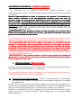
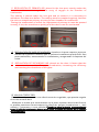
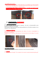
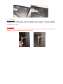
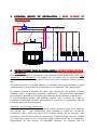
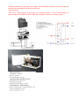
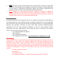
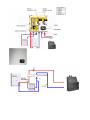
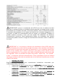
INSTRUCCIONES DE UTILIZACION INSTRUCTIONS OF UTILIZATION SERIE HYDROBRONPI Estimado cliente: Queremos darle las gracias por haber elegido uno de nuestros productos. El producto que usted ha adquirido, es algo de gran valor, por ello le invitamos a leer detenidamente este pequeño manual, para sacar sacar el máximo partido al aparato. Estimated client: We want to thank you for having chosen one of our products. The product that you have acquired, is something of great value, that´s why you to read carefully this small manual, to receive the best efficiency of device. ADVERTENCIAS GENERALES / GENERAL WARNINGS La instalación de la caldera se tiene que realizar conforme a las reglamentaciones locales, incluidas las que hagan referencia normas nacionales o europeas. Nuestra responsabilidad responsabilidad se limita al suministro del aparato. Su instalación se debe realizar conforme a los procedimientos previstos para este tipo de aparatos, según las prescripciones detalladas en estas instrucciones y las reglas de la profesión. Los instaladores serán cualificados cualificados y trabajarán por cuenta de empresas adecuadas, que se asuman toda la responsabilidad del conjunto de la instalación. RECOMENDAMOS QUE LA INSTALACIÓN SEA EFECTUADA SIEMPRE POR UN ESPECIALISTA CALEFACTOR. ¡¡¡IMPORTANTE!!!: Este producto incluye un bote bote de spray en el interior de la cámara de combustión u horno (en su caso), que debe ser extraido antes de la puesta en funcionamiento del mismo. The installation of the boiler has to be realized in conformity with the local, regulations including those that refer to national or European procedure. Our responsibility limits itself itself to the supply of the device. Its Its installation must be realized in conformity with the procedures foreseen for this type of devices, according to the detailed prescriptions in these these instructions and the rules of the profession. The installers will be qualified and work at the expense of suitable companies, which assume the whole responsibility of the set of the installation. WE RECOMMEND THAT THE INSTALLATION SHOULD BE ALWAYS CARRIED OUT BY A HEATING SPECIALIST. IMPORTANTLY!!!: This product includes a boat of spray inside the chamber of combustion or oven (in his case), that it must be extracted before the putting in functioning of the same one. 1. REGULACIONES / REGULATIONS. Para una perfecta regulación de la combustión, el modelo posee varios tipos de regulaciones. El funcionamiento es el que sigue: For a perfect regulation of the combustion, the chimney has several types of regulations. The functioning is the following: 1.1 REGULACION DE AIRE PRIMARIO: situada, en la parte inferior, justo debajo de la puerta nos permite la regulación de la entrada de oxigeno a la cámara de combustión. El cajón de la ceniza, está situado bajo la rejilla de fundición y para extraerlo se debe retirar previamente la misma. El cajón debe vaciarse con regularidad, para que la ceniza no pueda dificultar la entrada de aire primario a la cámara. Durante la combustión de leña, el ajuste de aire primario debe abrirse apenas, puesto que de lo contrario, la leña arde rápidamente y el aparato puede sobrecalentarse. 1.1 REGULATION OF PRIMARY AIR: placed in the low part, exactly under the door that allows us to regulate the entry of oxygen to the chamber of combustion. The ashtray, is placed under the cast grid and to extract it it is necessary to withdraw the same one before. The ashtray must be emptied regularly, because the ash can complicate primary air entry for the chamber of combustion. During the combustion of wood, the adjustment of primary air must be opened scarcely, if not, the wood burns quickly and the device can be overheated. . 1.2 REGULACION DE AIRE SECUNDARIO: situada en la parte superior justo por encima de la puerta. Favorece que el carbono incombusto pueda sufrir una post-combustión, aumentando el rendimiento y asegurando la limpieza del cristal. 1.2 REGULATION OF SECUNDARY AIR: placed on the door. It favors that the unburnt carbon could suffer a postcombustion, increasing the efficiency and assuring the cleanliness of the glass. 1.3 VALVUA CORTA TIRO. El modelo está provisto de una válvula corta tiro regulable, que permite regular el tiro de manera ideal. Mediante el tirador que encontramos en la parte superior derecha del frontal, es posible posicionar correctamente la válvula de humos (introducimos = abre válvula // extraemos = cerrar válvula). Cuando se abra la puerta, recomendamos tener la válvula totalmente abierta para evitar la salida de humos de la cámara de combustión. , 1.3 SHORT SHOT VALVE. The device is equipped by a short shot valve. To regulate it we use the knob that we find in the rgth part - top of the frontal view at the door. If we push it = valve opens , if we pull out = to close valve. Is recommended that before opening the door we make sure that the valve is open. to prevent the escape of smoke. smoke 2. COMPONEN COMPONENTES / COMPONENTS 2.1 COLOCACION MARCO El marco estándar que incorpora el aparato de serie, es desmontable, para facilitar la instalación del mismo. Para retirar el marco procederemos desatornillando los 4 tornillos situados en los laterales (2 en cada lateral). 2.1 FRAME PLACEMENT. The standard frame that incorporates the device of series is detachable to facilitate its installation . To remove the frame we will unscrew 4 screws placed in the wings (2 in each wing). 2.2 CAJON CENICERO Situado bajo la rejilla de fundición, debemos retirar ésta para extraerlo. 2.2 ASH TRY Is situated under the grill. For to extract it we must to extract previously the grill. 2.3 MANETA Maneta tipo “manos frías” para la apertura de la puerta. Para su correcta colocación la introduciremos de arriba hacia abajo y posteriormente realizaremos el giro . 2.3 HANDLE A handle type " cold hands " is used to open the door. To place it correctly we introduce it up to down and then we turn it. 3 ESQUEMA BASICO DE INSTALACION / BASIC SCHEME OF INSTALLATION vaso de expansion abierto red agua Valvula mezcladora 3 vias >= 50-55 ºC desagüe sistema de seguridad para enfriamiento del agua 1/2" 1" SONDA TEMPERATURA AGUA CALIENTE 3/8" 3/8" radiador bomba 1" 4 AGUA FRIA INSTRUCCIONES PARA EL INSTALADOR / INSTRUCTIONS FOR THE INSTALLER Con el hogar-caldera se suministra una válvula de sobre presión de 3 bar, cuya instalación es obligatoria. Al margen de la misma no se suministra otro elemento hidráulico de la instalación (llaves de corte, bombas, válvulas, sondas etc). De forma opcional, se puede adquirir los diferentes kits que ofertamos y cuyos componentes y características se describen en el apartado 7 de este manual. El modelo, efectúa la difusión del calor , por conducción del aparato al fluido radiante, que es el agua del circuito de calefaccion. Otra parte muy importante de la potencia generada se difunde por radiación de las paredes y convección. El funcionamiento normal del modelo, implica que la puerta de carga se encuentre totalmente cerrada, efectuando el control de la combustión con los controles descritos anteriormente. Conexión al circuito de calefacción: El modelo posee en el techo, tanto en su parte izquierda como en la derecha, dos racores de 1”, que utilizaremos para conectar la salida del circuito de calefacción (ida) y otros dos racores en la parte inferior de los laterales para conectar el retorno del circuito de calefacción. Se podrá utilizar tanto los racores de la derecha como los de la izquierda (según conveniencia de la instalación), lógicamente los dos racores no utilizados deberán ser tapados con sus correspondientes tapones. Asimismo presenta dos racores de 1/2” para la inserción de la sonda de temperatura para el sistema de seguridad y de la válvula de sobre presión y otros dos racores de 3/8” en el costado derecho, que son la entrada y salida del serpentín de acero inox. del sistema de seguridad. Es muy importante, que tanto la conexión, como el circuito de calefacción, sean realizados por personal profesional. El circuito deberá estar provisto de las medidas de seguridad correspondientes. El modelo nunca debe instalarse por termosifón, debe instalarse en un circuito con bomba aceleradora. Es recomendable instalar el termostato de arranque – paro , de la bomba lo mas cercano posible a la salida de agua caliente de la paila. Una vez conectada la chimenea al circuito de calefacción, llenaremos el circuito y probaremos el funcionamiento durante 2 – 3 días, descartando la posibilidad de fugas. Comprobado esto podremos revestir la chimenea. Se debe diseñar un circuito de calefacción que en su funcionamiento a máxima potencia el agua no sobrepase los 90ºC, para evitar sobretemperaturas y sobrepresiones. Para el caso en el que el agua del circuito alcanzara altas temperaturas que pudieran provocar un exceso de calor (agua hirviendo), el modelo incluye un sistema de seguridad que consiste en un serpentín de acero inox, inox que esta en contacto con el agua de la caldera y que mediante las oportunas conexiones disipa el exceso de calor.(ver esquema básico de instalación) . Asimismo se recomienda que el circuito posea otros sistemas para disipar el calor, un radiador de “fuga de calor”, una válvula de descarga térmica, una toma de agua fria…etc. El circuito deberá contar con una llave de purga en su parte inferior para facilitar el vaciado de éste. Cuando por motivos técnicos, no es posible la instalación con vaso de expansión abierto, será responsabilidad únicamente del instalador llevar a cabo la cerrado, para ello se deben de instalación de la caldera con vaso de expansión cerrado tener en cuenta una serie de requisitos mínimos de seguridad. 1) Hay que prever en la instalación de los radiadores no colocar cierres con válvulas termostáticas de zona en todos los radiadores. Siempre tiene que quedar una parte mínima de la instalación (radiadores) abierta para que el hogar calefactor pueda disipar el sobrecalentamiento. 2) Es obligatorio colocar una válvula de seguridad tarada a 3 Bar de presión. La instalación se debe llenar a 1 Bar de presión. 3) Se recomienda colocar una válvula de descarga térmica (95ºC). El desagüe de esta válvula debe ser amplio, estar en lugar visible y protegido para evitar derramamientos al exterior o salpicaduras. Imperativamente obligatorio evitar todo tipo de sifón en las tuberías que van al vaso de expansión. 4) La presión de carga del vaso debe ser la misma que la de llenado de la instalación. El volumen del vaso de expansión debe ser proporcional al volumen de agua de la instalación. 5) Es recomendable colocar en la instalación un termostato de mínima, que corte el circulador siempre que el agua de la paila del hogar este por debajo de los 50-55ºC. Esto evitara las condensaciones que se producen cuando se enciende el hogar. 6) Es recomendable que todos los componentes de la instalación (válvula de seguridad, circulador, vaso de expansión etc.)se coloque en el retorno The home - boiler is supplied with a over- presion valve of 3 bar. Any hydraulic part of the installation (keys of court, bombs, valves, probes etc) is supplied. The exception is the kits that are optional and their components and characteristics are described in the paragraph 7 of this manual. The model, effects the diffusion of the heat, for conduction of the device to the radiant fluid, which is the water of the circuit of heating. Another very important part of the generated power spreads for radiation of the walls and convection. The normal functioning of the model, implies that the door of load is totally closed, effecting the control of the combustion with the controls that are described previously. Connection to the circuit of heating: The model possesses in the top side and in the right, two fittings of 1 ", we will use the superior to connect the exit of the circuit of heating (way out) and the lower one to connect the return of the circuit of heating. It will be possible use the fittings of the right as well as the left ones (according to convenience of the installation), logically the two racores that are not used will have to be covered with their corresponding stoppers. "Likewise a racor of ½” is present" for the insertion of the probe of temperature for the safety system and other two racores of 3/8 " that are the entry and exit of the coil of stainless steel. of the safety system. It is very important, that both the connection and the circuit of heating, are realized by professional staff. The circuit is to be provided with the corresponding measures of safety. The model must never be established for boiler, must be installed in a circuit with accelerating bomb. It is advisable to install the thermostat of on-off, of the bomb nearby possible mas to the exit of warm water of the large water deposit. Once the chimney is connected to the circuit of heating, we will fill the circuit and will prove the functioning during 2 - 3 days, rejecting the possibility of escapes. Verified this we will be able to re-dress the chimney It is necessary to design a circuit of heating that when it is functioning on its highest efficiency, water can´t be warmer than 90ºC to avoid werheating and werpressure. For the case when the water of the circuit reaches high temperatures that could provoke a heat excess (when water Stara to boil), the he model includes a safety system that consists of a coil of stainless steel, steel that this in touch with the water of the boiler and that by means of the opportune connections removes the heat excess. (To see basic scheme of installation). It is recommended that the circuit should possess other systems to remove the heat, as radiator of " heat escape ", a valve of thermal unload, a capture of cold water … etc. The circuit will have to possess a key of purge in it low part to facilitate to empty it. When the installation is not possible with glass of expansion oponed for technical motives, it will be a responsibility only of the installer to carry out the installation of the boiler with glass of expansion closed, That´s why it´s necessary to pay attention on a series of minimal requirements of safety. 1) It is necessary to foresee in the installation of the radiators not to place closings with thermostatic valves of zone in all the radiators. Always there has to stay a minimal part of the installation (radiators) opened in order that the heating home could remove the overheating. 2) It is obligatory to place a safety valve adjusted to 3 bar of pressure. The installation must fill to 1 Bar of pressure. 3) It is recommended to place a valve of thermal unload (95ºC). The outlet of this valve must be wide, placed in visible and protected place to avoid spilling outside or splashes. It is obligatory to avoid all kinds of siphon in the pipelines that go to the glass of expansion. 4) The pressure of load of the glass must be the same that that of filling of the installation. The volume of the glass of expansion must be proportional to the water volume of the installation. 5) It is advisable to place in the installation a thermostat of minim, which cuts the circulator providing that the water of the large water deposit of the this home below it 50ºC. This will avoid the condensations that take place when the home is turns on. 6) It is advisable that all the components of the installation (safety valve, circulator, glass of expansion etc.) are placed in the return 5 KITS DE INSTALA INSTALACIÓN OPCIONALES / OPTIONAL KITS OF INSTALLATION Para complementar esta gama y garantizar un perfecto funcionamiento de la misma, se ofrecen unos kits pre-montados, que se conectan a la caldera simplemente uniendo los tubos del sistema hidráulico. To complement this range and to guarantee a perfect functioning of the same one, a few pre-mounted kits, which are offered connected to the boiler simply joining the pipes of the hydraulic system. • • KITKIT-1. Modulo para la gestión de instalaciones de calefacción alimentadas por una caldera a leña para la producción de agua caliente destinada a instalaciones de calefaccion doméstica y ACS. KIT-1. Module for the management of facilities of heating fed by a boiler to fuelwood for the production of warm water destined for facilities of domestic heating and hot sanitary water (HSW). La producción de ACS es prioritaria y viene automáticamente relevada del sistema hidraulico por mediación de un detector de flujo. Funcionamiento: La desviadora hace recircular el agua primaria en el intercambiador de placas cuando el flujostato detecta una solicitud de agua caliente sanitaria. HSW's production is priority and comes automatically relieved from the hydraulic system for mediation of a detector of flow. Functioning: The turn away makes re-circulate the primary water in the interchanger of plates when the detector of flor detects a request of warm sanitary water • • KITKIT-2. Modulo de interconexionado entre instalaciones a vaso de expansión abierto y vaso cerrado con regulador electrónico incluido. Permite gestionar el calor para la calefacción domestica desde dos fuentes alternativas de energia, cuyos circuitos están separados hidráulicamente KIT-2. Module of interhookup between facilities to glass of expansion opened and glass closed with electronic regulador included. It allows to manage the heat for the domestic heating from two alternative sources of energy, which circuits are separated hydraulically Funcionamiento: El modulo permite intercomunicarse con la calefacción doméstica acoplando al calor generado por una caldera de gas (o similar) tradicional el calor producido por una fuente de calor alternativa. Esto es posible gracias a un intercambiador térmico que permite transferir el calor entre dos circuitos hidráulicamente separados, uno de vaso cerrado (caldera) y uno de vaso abierto (fuente alternativa de calor, típicamente una caldera de leña o similares). Para poder hacer esto, el Kit prevé en su interior: . • un intercambiador de placas; . • dos bombas; . • una válvula desviadora; . • un regulador electrónico. (opcionalmente sin regulador: KIT -2B) Functioning: The module allows to be linked by the domestic heating connecting to the heat build-up for a gas boiler (or similar) traditionally the heat produced by an alternative heat source. This is possible thanks to a thermal interchanger that allows to transfer the heat between two circuits hydraulically separated, one of closed glass (boiler) and one of opened glass (alternative source of heat, typically a boiler of fuelwood or similar). To be able to do this, the Kit foresees in its interior: an interchanger of plates; two bombs; turn Hawai valve; an electronic regulator. (Optionally without regulator: KIT-2B) Çentralita IMPORTANTE: prever la instalación del KIT-B cerca de la caldera de leña para que la sonda prevista en el módulo pueda detectar en tiempo breve el calor proveniente de la caldera de leña. Si no fuese posible, sacar la sonda del módulo e instalarla directamente en los tubos del interior de la caldera alargando, si es necesario, el cable de conexionado entre la sonda y el regulador. También es posible sustituir la sonda “a clip”, por una sonda “de inmersión” de idénticas características eléctricas. Estas operaciones deben ser realizadas con mucha cautela para poder excluir el riesgo de interferencias eléctricas sobre el cable de la sonda. IMPORTANT: It´s necessary to foresee the installation of the KIT-B near the boiler of fuelwood in order that the probe foreseen in the module could detect in brief time the heat from the boiler of fuelwood. If it isn´t possible extract the probe of the module and install it directly in the pipes of the interior of the boiler lengthening, if it is necessary, the cable of hookup between the probe and the regulator. Also it is possible to replace the probe " paper clip ", for a probe " of dip " of identical electrical characteristics. These operations must be realized with great caution to be able to exclude the risk of electrical interferences on the cable of the probe. • CENTRALITA CENTRALITA FF-503. 503. Regulador para empotrar para instalaciones hidráulicas calentadas por combustible sólido. Funciones: • Producción de agua caliente para uso calefacción mediante chimenea; • Producción combinada de agua caliente para uso sanitario o calefacción, calefacción mediante chimeneas dotadas de intercambiador bitérmico o similares; • Producción combinada de agua caliente para uso sanitario o calefacción, calefacción mediante chimenea e intercambiador de placas externo; • Producción combinada de agua caliente para uso sanitario o calefacción calefacción, externo acción mediante chimenea y acumulador externo; • Producción de agua caliente para uso calefacción mediante chimenea en combinación con una caldera de gas; gas • SWITCHBOARD FF-503. Regulator to fix for hydraulic facilities warmed by solid fuel. Functions: • Production of warm water for use heating by means of chimney; • Production combined of warm water for sanitary use or heating, by means of chimneys provided with bithermic interchanger or similar; • Production combined of warm water for sanitary use or heating, by means of chimney and external interchanger of plates; • Production combined of warm water for sanitary use or heating, by means of chimney and external accumulator; • Production of warm water for use heating by means of chimney in combination with a gas boiler; Funcionamiento: La válvula desviadora conmuta el flujo del agua hacia la instalación cuando alcanza el setpoint progamado por el usuario (default = 45°C); El agua “recircula” en el intercambiador hasta que no alcance una temperatura suficiente para ceder calor a la instalación Functioning: The turn Hawai valve exchanges the flow of the water towards the installation when it reaches the setpoint programmed for the user (default = 45°C); The water "re-circulates" in the interchanger until it does not reach a sufficient temperature to yield heat to the installation Datos y modelos no son vinculantes: la empresa se reserva Los datos incluidos en este este manual no son vinculantes. dedeaportar La empresael se derecho reserva el derecho aportar modificaciones y mejoras sin ningún preaviso. modificaciones y mejoras sin The information included in this manual is not binding. The company reserves the right to contribute modifications and improvements without any notice. BRONPI CALEFACCIÓN S.L. Ctra. Córdoba-Málaga, Km. 70 Telf. 957 50 27 50 / Fax. 957 59 17 25 Apartado de Correos 255 14900 LUCENA (Córdoba) e-mail. [email protected] www.bronpi.com