1
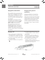
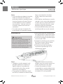
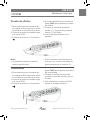
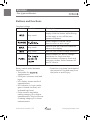
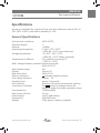
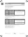
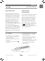
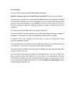
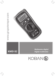
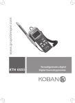
www.grupotemper.com
KM 8212
Multímetro tipo lápiz
Pen-type multimeter
KM 8212
Multímetro tipo lápiz
Contents
Información de seguridad
13
Recomendaciones previas
13
Durante el uso
13
Símbolos de seguridad
14
Mantenimiento
14
Descripción
14
Panel frontal
16
Botones y funciones
16
Especificaciones
18
Especificaciones generales
19
Especificaciones técnicas
19
Instrucciones de uso
21
Retención de datos
Retención de valor máximo
Selección de funciones
Escala manual
Apagado automático
Preparación para la medición
Tensión CC
Tensión CA
Resistencia
Prueba de diodos
Continuidad
Corriente CC
Corriente CA
Prueba lógica
Detección de tensión sin contacto (NVC)
Manual de instrucciones | 2
www.grupotemper.com
KM 8212
Multímetro tipo lápiz
Mantenimiento
Cambio de pilas
Cambio de puntas de prueba (clip the pinza)
Accesorios
www.grupotemper.com
Manual de instrucciones | 3
KM 8212
Multímetro tipo lápiz
Información de
seguridad
Atención
Par evitar el riesgo de incendio,
descarga eléctrica o daños
personales, siga con atención las
medidas de seguridad propuestas
en este manual antes de utilizar el
medidor.
Este medidor se ajusta a los
estándares GB/T 13978-92, a
GB4793 y 1-1995(IEC-61010-1:2001)
de seguridad para instrumentos
de medición electrónicos con una
categoría de sobretensión CAT 600V
y un grado de contaminación 2.
Siga todas las instrucciones de uso
y seguridad para asegurar un uso
correcto del mismo.
Con un uso y cuidado apropiados,
este multímetro digital le
proporcionará años de servicio
satisfactorio.
Recomendaciones previas
Cuando utilice el medidor siga todas
las normas de seguridad relativas a:
• Uso de protecciones contra
descargas eléctricas.
• Protección del medidor frente a un
uso inapropiado.
Manual de instrucciones | 4
Durante el uso
• Asegúrese de que el selector está
en la escala y función correctas.
• No realice mediciones que excedan
los valores límite de protección
indicados en las especificaciones.
• No toque los bordes de metal de
las puntas de prueba cuando el
medidor esté conectado al circuito
que va a medir.
• En modo manual, si desconoce el
valor que va a medir seleccione
la escala más alta primero y vaya
bajando según lo necesite.
• No tome mediciones de tensión si
el valor entre los terminales y la
toma de tierra es superior a 600V.
• Extreme las precauciones cuando
mida tensiones por encima de
60V CC o 30V AC RMS. Mantenga
los dedos por detrás de la barrera
de protección cuando realice las
mediciones.
• Nunca conecte las puntas de
prueba a través de una fuente de
tensión si el selector se encuentra
en modo resistencia, diodo o
continuidad, podría causar daños
en el instrumento.
• No mida la resistencia, capacidad,
diodo o la continuidad de circuitos
activos.
• Desconecte las puntas de prueba
del circuito antes de cambiar el
selector de función.
• No someta el medidor a ambientes
con alta presión o temperatura,
www.grupotemper.com
KM 8212
Multímetro tipo lápiz
polvo, gas explosivo o vapor.
• Deje de utilizar el medidor si
observa algún tipo de anormalidad
o incidencia.
• No utilice el medidor si la carcasa
posterior y la tapa de las pilas del
mismo no están correctamente
fijadas a su posición original.
Símbolos de seguridad
Precaución: Consulte el
manual de instrucciones.
Doble aislamiento (CAT II)
CAT III
Conforme a la
normativa IEC1010-1
para sobrecargas en
instalaciones de categoría
III, con un nivel de
contaminación de grado
2.
Conforme a las directivas
de la Unión Europea
Toma de tierra
AC
Corriente alterna
DC
Corriente continua
CA o CC
Diodo
Señal acústica de
continuidad
M.H
Valor máximo
D.H
Retención de datos
AUTO
Escala automática
www.grupotemper.com
Indicador de batería baja
Mantenimiento
• La reparación del instrumento
debe ser realizada por personal
cualificado.
• Desconecte las puntas de prueba
de los circuitos que está midiendo
antes de retirar la tapa de las pilas.
• Para evitar lecturas erróneas que
puedan causar daños personales o
en el aparato, cambie las pilas tan
pronto como aparezca el símbolo
en la pantalla.
• Limpie en medidor con un paño
húmedo y un detergente neutro,
no utilice nunca productos
abrasivos o disolventes.
• Coloque el selector rotatorio en la
posición OFF cuando no utilice en
medidor.
• Si no va a utilizar el medidor en un
largo periodo de tiempo, retire las
pilas.
Descripción
Este medidor es un instrumento
profesional portátil con una cómoda
pantalla LCD de fácil lectura.
De fácil manejo con una mano, viene
equipado con protección
contra sobrevoltaje e indicador de
baja batería. Ideal para ser usado en
campo, taller, escuela y en
aplicaciones domésticas.
Manual de instrucciones | 5
KM 8212
Multímetro tipo lápiz
Cuenta con función de escala
automática y escala manual, función
de apagado automático y de
retención de datos y máximo valor.
Durante su uso, muestra
automáticamente el valor y la unidad
de medición.
Panel frontal
1. Sonda positiva de prueba (+)
2 Cubierta de la sonda de prueba (extraible)
3. Indicadores LED
4. Anillo protector
5. Selector giratorio
6. Botón de retención de datos (HOLD)
7. Botón de selección de escala (RAN)
8. Botón de función (FUNC)
9. Botón de retención del valor máximo (MAX)
10. Botón de detección de tensión sin contacto (NVC)
11. Panel
12. Pantalla LCD
13. Toma COM (-)
Manual de instrucciones | 6
www.grupotemper.com
KM 8212
Multímetro tipo lápiz
Botones y funciones
Botones de función
Botón
Función
Descripción
Pulse este botón para retener en la pantalla
el valor medido. Mantenga el botón
En cualquier modo
pulsado mientras enciende el medidor para
anular la función de apagado automático.
Púlselo para seleccionar el modo escala
manual. Manténgalo pulsado para volver al
modo automático de selección de escalas.
En cualquier modo
Pulse este botón para retener en la pantalla
el valor máximo medido.
En cualquier modo
Púlselo para detectar la tensión sin
contacto.
Permite seleccionar entre tensión CA y
CC. Manténgalo pulsado para la prueba
lógica. Selecciona entre resistencia, diodo,
continuidad y los modos corriente alterna
CA y corriente continua CC.
• Selector Rotatorio: permite
seleccionar las diferentes
funciones.
• Sonda de prueba: para mediciones
.
• Toma COM: entrada para la punta
de prueba.
• Pantall LCD: muestra los resultados
de las mediciones.
• Indicador LED: en el modo de
prueba lógica, el verde es el
indicador de bajo nivel y el rojo el
de alto nivel.
• Cubierta de la sonda: se utiliza
para mediciones de categoría III
www.grupotemper.com
o superiores. Gírela para retirarla
si va a realizar mediciones de
categoría II o menores.
• Anillo protector: Mantenga las
manos por detrás de este aro de
protección y alejadas de la sonda
para evitar lesiones.
Manual de instrucciones | 7
KM 8212
Multímetro tipo lápiz
Especificaciones
Se especifica una precisión para un periodo de un año tras la calibración y
18ºC a 28ºC (64ºF a 82ºF) con una humedad relativa inferior al 75%.
Especificaciones generales
Tensión máxima:
600V CAT. III
Nivel de contaminación:
2
Altitud:<2000m
Temperatura de operatividad:
0~40ºC, 32ºF~122ºF
(<80% RH, <10ºC sin condensación)
Temperatura de almacenaje:
-10~50ºC, 14ºF~122ºF
(<80% RH, <10ºC sin pilas)
Coeficiente de temperatura:
0.1x (precisión especificada)/ºC
(<18ºC o >28ºC)
Máx. voltaje entre terminales y puesta a tierra:
600V CA o CC
Escala Auto/manual:
Sí
Pantalla:
LCD de 20mm
Max valor mostrado:
1999 cuentas (3 1/2)
Indicación de polaridad:
Símbolo
indica polaridad negativa
Indicación de sobre escala:
La pantalla muestra“OL”
Tasa de muestreo:
aprox. 0,4 segundos
Unidad mostrada:
muestra de función y capacidad eléctrica
Indicación de batería baja:
Símbolo
en pantalla indica batería baja.
Fusible de protección:
FF400mA/600V
Tiempo de apagado automático: 15 min.
Alimentación:
2 pilas 1.5V AAA
Dimensiones:208x38x29 mm.
Peso:
129g aprox. (incluyendo pila)
Manual de instrucciones | 8
www.grupotemper.com
KM 8212
Multímetro tipo lápiz
Especificaciones técnicas
(Temperatura ambiente: 23 +- 5ºC,
humedad relativa: <75%)
Tensión CC
Escala
Resolución
200mV
0.1mV
2V
0.001V
20V
0.01V
200V
0.1V
Precisión
±0.7% de lect ± 2 digitos
600V
1V
Impedancia de entrada: 10MΩ.
Protección contra sobrecargas: Escala 200mV: 250V CC o CA rms.
Escalas 2V-600V : 600V CC o CA rms.
Máxima tensión de entrada: 600V CC
Tensión CA
Escala
Resolución
200mV
0.1mV
2V
0.001mV
20V
0.01mV
200V
0.1V
Precisión
±0.8% de lect ± 3 digitos
±1.0% de lect ± 3 digitos
600V
1V
Impedancia de entrada: 10MΩ.
Protección contra sobrecargas: Escala 200mV: 250V CC o CA rms.
Escalas 2V-600V : 600V CC o CA rms.
Respuesta: promedio (rms de la onda sinusoidal)
Máxima tensión de entrada: 600V AC rms
www.grupotemper.com
Manual de instrucciones | 9
KM 8212
Multímetro tipo lápiz
Resistencia
Escala
Resolución
Precisión
200Ω
0.1Ω
±1.0% de lect ± 3 digitos
2kΩ
0.001kΩ
20kΩ
0.01kΩ
200kΩ
0.1kΩ
2MΩ
0.001MΩ
±1.0% de lect ± 1 digito
20MΩ
0.01MΩ
±1.0% de lect ± 5 digitos
Voltaje de circuito abierto: 250mV
Protección contra sobrecarga: 250V CC o rms CA
Continuidad
Función
Descripción
Si la resistencia es inferior a 50Ω el avisador acústico de
continuidad sonará.
Voltaje de circuito abierto: aprox. 500V
Protección contra sobrecarga: 250V CC o rms CA
Prueba de diodos
Función
Resolución
0.001V
Descripción
Se muestra el voltaje directo
aproximado del diodo
Corriente CC directa: aprox. 1mA
Voltaje CC inverso: aprox.1.5V
Protección contra sobrecarga: 250V CC o rms CA
Corriente CC
Escala
Resolución
20mA
0.01mA
Precisión
±1.5% de lect ± 3 digitos
200mA
0.1mA
Protección contra sobrecargas: fusible rearmable
Manual de instrucciones | 10
www.grupotemper.com
KM 8212
Multímetro tipo lápiz
Corriente CA
Escala
Resolución
20mA
0.01mA
Precisión
±2.0% de lect ± 3 digitos
200mA
0.1mA
Protección contra sobrecargas: fusible rearmable
Escala de frecuencia: 4Hz-200Hz
Respuesta: promedio (rms de la onda sinusoidal)
Prueba lógica
Función
Descripción
Logic
Impedancia de entrada: 10MΩ.
Protección contra sobrecarga: 250V CC o rms CA
Instrucciones de uso
Selección de Funciones
Retención de datos
En los modos tensión/corriente,
pulse el botón FUN” para
seleccionar entre CA/CC. En
la posición resistencia/diodo/
continuidad, pulse FUNC para
escoger unos de estos modos.
Cuando realice una medición, pulse
el botón HOLD para retener en la
pantalla el valor de la lectura actual.
El símbolo D.H aparecerá en la
pantalla; pulse de nuevo el botón
para salir de esta función.
Retención de valor
máximo
Pulse el botón MAX cuando esté
realizando mediciones y la pantalla
mostrará el valor máximo grabado.
El símbolo M.H aparecerá en la
pantalla. Pulse de nuevo el botón
MAX que la pantalla vuelva al modo
normal.
www.grupotemper.com
Escala manual
En las funciones tensión/
corriente/resistencia, el modo de
funcionamiento por defecto es el
automático AUTO; si desea cambiar
a manual, deberá pulsar el botón
RAN. Cada vez que pulse el botón la
escala subirá. Una vez haya llegado
a la más alta, presione el botón
para volver a la escala más baja.
Mantenga pulsado el botón RAN
para volver a modo automático.
Manual de instrucciones | 11
KM 8212
Multímetro tipo lápiz
Apagado automático
Este medidor lleva incorporado un
dispositivo de apagado automático.
Transcurridos 14 minutos sin uso,
el medidor emitirá 5 bips cortos y 1
minuto más tarde 1 bip largo antes
de apagarse.
Para poner en marcha de nuevo
el medidor gire el selector o pulse
cualquiera de los botones FUNC,
MAX o RAN indistintamente.
Para desactivar la función de
apagado automático, presione el
botón HOLD cuando encienda el
medidor. Así mismo, esta función
volverá a estar activa una vez apague
el medidor.
Tensión CC
1.Para mediciones en instalaciones
de categoría III o superiores utilice
la cubierta de la sonda de prueba.
2.Conecte la punta de prueba negra
a la toma COM.
3.Coloque el selector en la posición
.
Manual de instrucciones | 12
Preparación para la
medición
Coloque el selector en la posición
deseada. Si está en modo manual,
seleccione la escala más alta primero
si desconoce el valor que va a medir
y baya bajando según sea necesario.
Cuando conecte el medidor a un
circuito, enganche primero la punta
de prueba común y luego la sonda
de prueba.
4.El modo predefinido es tensión CC.
Si desea cambiar a modo manual
pulse RAN.
5.Conecte la sonda de prueba y la
punta de prueba roja en la fuente
de alimentación o carga a medir.
6.La pantalla mostrará el valor
medido. Tenga en cuenta la
polaridad de la punta de prueba en
mediciones de tensión CC.
www.grupotemper.com
KM 8212
Multímetro tipo lápiz
Atención
Para evitar descargas eléctricas,
daños en el medidor o lesiones,
no mida tensiones que pudieran
sobrepasar los 600V CC
Nota:
• En las escalas más bajas de tensión,
antes de conectar la sonda y la
punta de prueba la pantalla puede
mostrar lecturas erróneas. Esto es
normal debido a que el medidor
Tensión CA
Atención
Para evitar descargas eléctricas,
daños en el medidor o lesiones,
no mida tensiones que pudieran
sobrepasar los 600V CA rms
1.Para mediciones en instalaciones
de categoría III o superiores utilice
la cubierta de la sonda de prueba.
2.Conecte la punta de prueba negra
a la toma COM.
www.grupotemper.com
es muy sensible . Una vez hecha
la conexión, aparecerá la lectura
verdadera.
• En modo manual, se mostrará el
símbolo OL en la pantalla cuando
haya una situación de sobreescala, seleccione una escala
mayor.
• Para realizar mediciones en modo
manual, si no conoce de antemano
el valor que va a medir seleccione
primero la escala más alta y vaya
bajando según sea necesario.
3.Coloque el selector en la posición
.
4.El modo predefinido es tensión CC.
Pulse el botón FUNC para cambiar
a tensión CA. Si desea cambiar a
modo manual pulse RAN.
5.Conecte la sonda de prueba y la
punta de prueba roja a través de
la fuente de alimentación o carga
a medir.
6.Lea los valores medidos en la
pantalla.
Manual de instrucciones | 13
KM 8212
Multímetro tipo lápiz
Nota:
• En las escalas más bajas de tensión,
antes de conectar la sonda y la
punta de prueba la pantalla puede
mostrar lecturas erróneas. Esto es
normal debido a que el medidor
muy sensible . Una vez hecha la
conexión, aparecerá la lectura
verdadera.
• En modo manual, el símbolo OL
se mostrará en la pantalla cuando
haya una situación de sobreescala, seleccione una escala
mayor.
• Para realizar mediciones en modo
manual, si no conoce de antemano
el valor que va a medir seleccione
primero la escala más alta y vaya
bajando según sea necesario.
• La escala de Milivoltios (mV) sólo
está disponible en modo manual.
Resistencia
1.Para mediciones en instalaciones
de categoría III o superiores utilice
la cubierta de la sonda de prueba.
2.Conecte la punta de prueba negra
a la terminal COM.
3.Coloque el selector en la posición
Ω. Pulse el botón RAN si desea
cambiar a modo manual.
4.Conecte la sonda de prueba y
la punta de prueba roja en la
resistencia a medir.
Atención
Para evitar un posible riesgo de
sufrir una descarga eléctrica,
antes de realizar mediciones de
resistencia asegúrese de que
todos los condensadores han sido
completamente descargados.
Nota:
• Cuando en modo manual en la
pantalla aparece el símbolo OL
significa que se ha producido
una situación de sobre-escala,
seleccione una superior.
• Si la resistencia medida es mayor
de 1MΩ, al medidor le llevará unos
Manual de instrucciones | 14
segundos mostrar una lectura
estable; esto es normal cuando se
miden resistencias muy altas.
• Cuando las puntas no estén
conectadas o cuando midamos un
circuito abierto también aparecerá
el símbolo OL en la pantalla.
www.grupotemper.com
KM 8212
Multímetro tipo lápiz
Prueba de diodos
1.Para mediciones en instalaciones
de categoría III o superiores utilice
la cubierta de la sonda de prueba.
2.Conecte la punta de prueba negra
a la toma COM.
3.Coloque el selector en la posición
.
4.El modo predefinido es resistencia,
pulse FUNC para cambiar a prueba
de diodos.
5.Conecte la sonda de prueba al
ánodo (+) y la punta de prueba al
cátodo (-) del diodo.
6.Lea los valores medidos en la
pantalla.
Nota:
• La pantalla muestra la caída de
tensión aproximada.
• Si las conexiones está hechas a la
inversa o no se han conectado las
puntas, aparecerá el símbolo OL.
Continudad
4.El modo predefinido es resistencia,
pulse FUNC para cambiar a prueba
de continuidad.
5.Conecte la sonda y la punta de
prueba a través del circuito que va
a medir.
6.Si la resistencia es menor de 50Ω
saltará el avisador acústico.
1.Para mediciones en instalaciones
de categoría III o superiores utilice
la cubierta de la sonda de prueba.
2.Conecte la punta de prueba negra
a la toma COM.
3.Coloque el selector en la posición
.
www.grupotemper.com
Manual de instrucciones | 15
KM 8212
Multímetro tipo lápiz
Atención
Para evitar un posible riesgo de
sufrir una descarga eléctrica,
antes de realizar mediciones de
resistencia asegúrese de que
todos los condensadores han sido
completamente descargados.
Corriente CC
Atención
Para evitar descargas eléctricas o
daños personales y en el medidor,
nunca realice mediciones de
corriente si la tensión del circuito
abierto supera los 250V.
1.Para mediciones en instalaciones
de categoría III o superiores utilice
la cubierta de la sonda de prueba.
2.Conecte la punta de prueba negra
a la toma COM.
3.Coloque el selector en la pos.
.
Corriente CA
Warning
Para evitar descargas eléctricas o
daños personales y en el medidor,
nunca realice mediciones de
corriente si la tensión del circuito
abierto supera los 250V.
1.Para mediciones en instalaciones
Manual de instrucciones | 16
Note:
• Si las puntas no están conectadas
o la resistencia es mayor de 200Ω,,
la pantalla mostrará el símbolo OL.
4.El modo predefinido es corriente
CC, pulse RAN si desea cambiar a
modo manual.
5.Conecte la sonda y la punta de
prueba en serie con el circuito que
va a medir.
6.Lea los valores medidos en la
pantalla. Cuando haga mediciones
de corriente CC, observe la
polaridad de la sonda de prueba.
Note:
• Cuando esté en modo manual, si
en la pantalla aparece el símbolo
OL significa que se ha producido
una situación de sobre-escala,
debe seleccionar una superior.
de categoría III o superiores utilice
la cubierta de la sonda de prueba.
2.Conecte la punta de prueba negra
a la toma COM.
3.Coloque el selector en la pos.
.
4.Pulse FUNC para cambiar a
corriente alterna CA. Pulse el
botón RAN si desea pasar a modo
manual.
5.Conecte la sonda y la punta de
prueba a través del circuito que va
a medir.
www.grupotemper.com
KM 8212
Multímetro tipo lápiz
6.Lea en la pantalla los valores
medidos. observe la polaridad de
la sonda de prueba.
Nota:
Si aparece el símbolo OL en
la pantalla significa que se ha
producido una situación de sobreescala, seleccione una superior.
Prueba lógica
botón FUNC y toque la sonda de
prueba. Las luces LED cerca del
borde del medidor indicarán el
nivel lógico de corriente ( el rojo
indica nivel “alto” o “1” y el
verde nivel “bajo” o “0”).
6.La pantalla mostrará el nivel lógico
de corriente junto con los la
tensión medida (el símbolo
representa nivel “alto” y
nivel “bajo”).
Atención
Para evitar descargas eléctricas o
daños personales y en el medidor,
nunca realice mediciones de
tensión superiores a los 100V CA
rms.
1.Para mediciones en instalaciones
de categoría III o superiores utilice
la cubierta de la sonda de prueba.
2.Conecte la punta de prueba negra
a la toma COM.
3.Coloque el selector en la posición
LOGIC.
4.Conecte la punta de prueba negra
a la toma de tierra del circuito (-).
5.Para medir, mantenga pulsado el
Detección de tensión sin
contacto
Atención
Para evitar descargas eléctricas o
daños personales y en el medidor,
nunca realice mediciones de
tensión superiores a los 100V CA
rms.
1.Coloque el selector en cualquier
www.grupotemper.com
Note:
• Si las puntas no están conectadas
o la tensión es menor de 1.5V, el
LED será verde.
• Durante la prueba lógica debemos
mantener pulsado el botón FUNC.
posición que no sea OFF y
mantenga pulsado el botón NCV.
2.Acerque la punta del medidor
a la fuente de alimentación a la
conductor. Si detecta una tensión
mayor de 110VCA, el avisador
emitirá unos bips y el indicador de
NCV que se encuentra cerca de la
punta parpadeará.
Nota:
• Puede existir tensión incluso si el
Manual de instrucciones | 17
KM 8212
Multímetro tipo lápiz
medidor no lo indica. No confíe
únicamente en la detección de
NCV para determinar la presencia
de tensión, las lecturas pueden
verse afectadas por el diseño del
enchufe, el grosor del aislamiento
y otros factores.
• El indicador LED de NCV
parpadeará cuando mida tensiones
de CC y CA debido a la presencia
de tensión inducida.
• En ocasiones, interferencias
medioambientales externas de
fuentes adicionales pueden falsear
y cambiar la detección de NCV.
Mantenimiento
Si el aislamiento de las puntas está
dañado, o algún cable ha quedado
expuesto debe cambiarlas.
Atención
Para evitar una posible descarga
eléctrica o daños personales y en
el medidor, retire las puntas de
prueba antes de abrir la tapa de
las pilas.
Cambio de pilas
Accesorios
Punta de
prueba
Clas.: 600V 10A
(T3060A)
1
Pinza
Clas.: 600V 10A
1
Pilas
1.5V AAA
2
Manual
1
• Cuando las pilas necesiten ser
sustituidas, aparecerá el símbolo
en la pantalla.
• Desenrosque los tornillos de la
tapa y quítela.
• Cambie las usadas por unas nuevas
del modelo AAA.
• Vuelva a colocar la tapa y fíjela al
medidor.
Replacing the test lead
Atención
Cambie las puntas por otras
de la misma clasificación o por
una superior a la de las pinzas
suministradas con el medidor.
Manual de instrucciones | 18
www.grupotemper.com
KM 8212
Pen type multimeter
Contents
Safety Information
13
Preparing for use
13
During use
13
Safety symbols
14
Maintenance
14
Description
14
Front panel
16
Buttons and functions
16
Specifications
18
General specifications
19
Technical specifications
19
Using the meter
21
Reading Hold
Max Hold
Function button
Manual range
Auto Power Off
Preparing for measurement
DC Voltage
AC Voltage
Resistance
Diode test
Continuity
DC Current
AC Current
Logic test
Non-Contact Voltage (NVC)
www.grupotemper.com
Instructions manual | 19
KM 8212
Pen type multimeter
Maintenance
Replacing the batteries
Replacing the Test lead (or alligator clip)
Accesories
Instructions manual | 20
www.grupotemper.com
KM 8212
Pen type multimeter
Safety information
Warning
To reduce the risk of fire, electrical
shock, product damage or
personal injury, please follow the
safety instructions described in
the user manual. Read the user´s
manula before using the meter.
This instrument conforms to GB/T
13978-92 for digital multimeter
technical standards, as well as
GB4793. 1-1995 (IEC-61010-1:2001)
safety standards for electronic
measuring instruments with a
safety category of CAT III 600V and
pollution degree of 2.
Follow all safety instructions to
ensure safe use of the instrument.
Following these guidelines will yield
many years of satisfactory service.
Preparing for use
During use, observe all standards
safety rules:
• Use protection to prevent electric
shock.
• Do not misuse the instrument.
During Use
• Always make sure the rotary switch
is at the correct function and
range.
www.grupotemper.com
• Do not exceed the protection limit
values indicated for each function.
• Do not touch test lead tips while
connected to a measurement
circuit.
• In manual range, if the value to be
measured is unknown, select the
highest range first and lower as
needed.
• Do not measure voltages that
may exceed 600V between the
terminals and ground.
• Always be careful whren working
with voltages above 60V DC or 30V
AC RMS. Keep fingers behind the
probe barriers while measuring.
• Never connect the meter leads
across a voltage source while the
rotary switch is in the resistance,
diode or continuity mode. Doing
so can damage the meter.
• Do not perform resistance, diode
and continuiity measurements on
powered circuits.
• Disconnect the test leads from the
circuit before changing functions
on the rotary switch.
• Do not place the meter in an
enviroment with high pressure/
temperature, dust, explosive gas or
vapor.
• Stop using the meter if any
abnormalities or failures occuer.
• Do not connect the test leads to a
circuit without the battery securely
fastened.
• Do not store the meter in an area
of direct sun light.
Instructions manual | 21
KM 8212
Pen type multimeter
Safety Symbols
Important safety
information. See manula for
details.
Double insulation
protection (category II).
Conforms to European
Union directives
Earth ground
AC
Alternating current
DC
Direct Current
AC or DC
Diode
Continuity Buzzer
M.H
Max Hold
D.H
Data Hold
AUTO Auto-range
Low battery
Maintenance
• Do not use abrasives or solvents
on the meter, use a damp cloth
and mild detergent only.
• Move the rotary switch to the OFF
position when the meter is not in
use.
• Remove the batteries if the meter
is not going to be used for an
extended period of time.
General Description
This meter is a professional, portable
meter with an easy to red LCD
screen.
Easy to use with one hand, overload
protection provided, low battery
indication and suitable for use in
factories, schools, by enthusiasts and
hobbyists alike.
Both auto-range and manual-range
available.
Automatic power off feature.
Data hold and Max. hold features.
During use, the instrument
automatically shows the value and
unit of the measurement.
• Repairs should only be
implemented by trained personnel.
• Remove test leads from
measurement circuits before
opening the battery cover.
• To avoid false readings, which
could lead to possible electric
shock or personal injury, replace
the battery as soon as the battery
indicator
appears.
Instructions manual | 22
www.grupotemper.com
KM 8212
Pen type multimeter
Front panel
1. Positive test probe (+)
2 Probe cover (removable)
3. LED indicators
4. Protective ring
5. Rotary switch
6. Data hold button (HOLD)
7. Range button (RAN)
8. Function button (FUNC)
9. Max hold button (MAX)
10. Non-contact voltage button (NVC)
11. Panel
12. LCD screen
13. COM jack (-)
www.grupotemper.com
Instructions manual | 23
KM 8212
Pen type multimeter
Buttons and functions
Function buttons
Button
Function
Description
Any mode
Press to hold the current reading on the
display. Hold the button while turning
on the meter to turn off the auto
npower off feature.
Switch ranges in manual-range.
Hold to return to auto-range.
Any mode
Press to hold the maximun measured
value on the display.
Any mode
Hold for non-contact voltage detection.
Switch between AC and DC voltage.
Hold down for Logic level test.
Switch between resistance, diode and
continuity modes. Switch between AC
and DC current.
Rotary switch: select between
functions.
• Test probe: for
measurements.
• COM jack: commoen test lead
input.
• LCD display: shows results of
measurements.
• LED indicator: in Logic mode,
green inicated low level, red
indicated high level.
• Probe cover:b used when
making category III or higher
measurements. Twist to remove
if making category II or lower
measurements.
Instructions manual | 24
• Protection ring: keep hands behind
the protection ring and away from
the probe to avoid injury.
www.grupotemper.com
KM 8212
Pen type multimeter
Specifications
Accuracy is specified for a period of one year after calibration and at 18°C to
28°C (64°F to 82°F) with relative humidity to 75%.
General Specifications
Environment conditions:
600V CAT. III
Pollution degree:
2
Altitude:<2000m
Operating temperature:
0~40ºC, 32ºF~122ºF
(<80% RH, <10ºC noncondensing)
Storage temperature:
-10~50ºC, 14ºF~122ºF
(<80% RH, <10ºC battery removed)
Temperature Coefficient:
0.1x (specified accuracy)/ºC
(<18ºC or >28ºC)
MAX. Voltage between terminals and earth ground:
600V AC or DC
Auto/manual range:
Yes
Display:20mm LCD
Max show value:
1999 (3 1/2)
Polarity indication:
indicates negative polarity
Over range indication:
Display “OL”
Sampling time:
approx. 0.4 second
Unit showing:
showing of function and electrical capacity.
Low battery indication:
The
symbol is displayed when the
battery is under the proper operation range
Fuse protection:FF400mA/600V
Auto power off time:
15 min.
Power supply:
1.5Vx2 AAA battery
Dimensions:208x38x29 mm.
Weight:
129g. approx. (battery included).
www.grupotemper.com
Instructions manual | 25
KM 8212
Pen type multimeter
Technical specifications
(ambient temperature: 23±5ºC,
relative humidity <75%)
DC voltage
Range
Resolution
200mV
0.1mV
2V
0.001V
20V
0.01V
200V
0.1V
Accuracy
±0.7% of rdg ± 2 digit
600V
1V
Input impedance: 10MΩ.
Overload protection: 200mV range: 250V DC or AC rms.
2V-600V ranges: 600V DC or AC rms.
Max. input voltage: 600V DC
AC voltage
Range
Resolution
200mV
0.1mV
2V
0.001mV
20V
0.01mV
200V
0.1V
Accuracy
±0.8% of rdg ± 3 digits
±1.0% of rdg ± 3 digits
600V
1V
Input impedance: 10MΩ
Overload protection: 200mV range: 250V DC or AC rms.
2V-600V ranges: 600V DC or AC rms.
Frequency range: 40Hz to 400Hz.
Response: Average (rms of sine wave).
Max. input voltage: 600V AC rms
Instructions manual | 26
www.grupotemper.com
KM 8212
Pen type multimeter
Resistance
Range
Resolution
Accuracy
200Ω
0.1Ω
±1.0% of rdg ± 3 digits
2kΩ
0.001kΩ
20kΩ
0.01kΩ
200kΩ
0.1kΩ
2MΩ
0.001MΩ
±1.0% of rdg ± 1 digit
20MΩ
0.01MΩ
±1.0% of rdg ± 5 digits
Overload Protection: 250V DC or 250V AC rms.
Open circuit voltage: approx. 250mV.
Continuity
Function
Description
If measured resistance is less than 50Ω, buzzer will sound.
Overload Protection: 250V DC or 250V AC rms.
Open circuit voltage: approx. 500mV.
Diode test
Function
Resolution
0.001V
Description
Displays approx. forward biased
voltage
Forward DC Current: approx. 1mA
Reversed DC Voltage: approx. 1.5V
Overload protection: 250VDC or 250VAC rms.
DC Current
Range
Resolution
20mA
0.01mA
200mA
0.1mA
Overload Protection: resettable fuse
www.grupotemper.com
Accuracy
±1.5% of rdg ± 3 digits
Instructions manual | 27
KM 8212
Pen type multimeter
AC Current
Range
Resolution
20mA
0.01mA
Accuracy
±2.0% of rdg ± 3 digits
200mA
0.1mA
Overload Protection: Resettable fuse
Frequency Range: 4Hz-200Hz
Response: Average (rms of sine wave).
Logic test
Function
Description
Logic
Input impedance: 10MΩ
Overload protection: 250VDC or 250VAC rms.
Using the meter
Function button
Reading Hold
In voltage/current modes, press the
FUNC button to switch between
AC/DC. At the resistance/diode/
continuity position, press FUNC to
switch between these modes.
During measurement, press HOLD
button to keep the current reading
on the display. D.H will appear on
the display. Press HOLD again to
return to norma display.
Max Hold
During measurement, press the MAX
button and the disply will show the
maximum value recorded. M.H will
appear on the display. Press MAX
again to return to normal display.
Instructions manual | 28
Manual range
In voltage/current/resistance modes,
the default range is AUTO. Press the
RAN button to switch to manual
range. Each press of the button
increases the range, and returns to
the lowest range once pressed in the
highest range. Hold down RAN to
return to auto-range.
www.grupotemper.com
KM 8212
Pen type multimeter
Auto Power Off
The meter has an auto power off
feature that will turn the meter off
automatically if left on. After approx.
14 minutes of non-use, the meter
will sound 5 short beeps and then 1
minute later the meter will sound 1
long beep and turn itself off.
After auto power off has occurred,
either move the rotary switch or
press FUNC, MAX or RAN buttons to
turn the meter back on.
If you hold down the HOLD button
when turning on the meter, this will
disable the auto power off function.
The auto power off function will reenable after the meter is turned off
again.
DC Voltage
1.Use the probe cover if making
measurements on category III or
above installations.
2.Insert the black test lead into the
COM jack.
3.Turn the rotary switch to the
position.
www.grupotemper.com
Preparing for
measurement
Select the desired function using the
rotary switch. If in manual mode,
select the highest range first if the
value to be measured is unknown
beforehand and lower as needed.
When connecting the meter to a
circuit, connect the common lead
first then the meter’s test probe.
lf the battery voltage becomes <2.4V,
the
symbol appears on the
display. Replace the batteries before
making measurements.
4.The default mode is DC voltage.
Press RAN to switch to manual
range if needed.
5.Connect the test probe and test
lead across the voltage source or
load for measurement.
6.The display will show the measured
value. Observe the polarity of
the test probe for DC voltage
measurements.
Instructions manual | 29
KM 8212
Pen type multimeter
Warning
To prevent electric shock and
damage to the meter or personal
injury, do not measure voltages
that may exceed 600V DC.
Note:
• Before connecting the probe and
test lead at lower voltage ranges,
the display may show erratic
AC Voltage
Warning
To prevent electric shock and
damage to the meter or personal
injury, do not measure voltages
that may exceed 600V AC rms.
1.Use the probe cover if making
measurements on category III or
above installations.
Instructions manual | 30
readings. This is normal because
the meter is highly sensitive.
Once a connection is made, the
true reading will be displayed.
• “OL” indicated an over-range
situation in manual mode. A higher
range should be selected.
• In manual mode, select the highest
range first if the value to be
measured is unknown beforehand
and lower as needed.
2.Insert the black test lead into the
COM jack.
3.Turn the rotary switch to the
position.
4.The default mode is DC voltage.
Press FUNC to switch to AC
voltage. Press RAN to switch to
manual range if needed.
5.Connect the test probe and test
lead across the voltage source or
load for measurement.
6.The display will show the measured
value.
www.grupotemper.com
KM 8212
Pen type multimeter
Note:
• Before connecting the probe and
test lead at lower voltage ranges,
the display may show erratic
readings. This is normal because
the meter is highly sensitive.
Once a connection is made, the
true reading will be displayed.
• “OL” indicated an over-range
situation in manual mode. A higher
range should be selected.
• In manual mode, select the highest
range first if the value to be
measured is unknown beforehand
and lower as needed.
• Milivolt range (mV) is only
available in manual range mode.
Resistance
1.Use the probe cover if making
measurements on category III or
above installations.
2.Insert the black test lead into the
COM jack.
3.Turn the rotary switch to the Ω
position. Press RAN to switch to
manual range if needed.
4.Connect the test probe and test
lead across the resistance for
measurement.
5.The display will show the measured
value.
Note:
• “OL” indicated an over-range
situation in manual mode. A higher
range should be selected.
• lf the resistance measured is
greater than 1MΩ,the meter may
take a few seconds to get a stable
reading. This is normal for high
resistance measurements.
• When the leads are not connected
or when measuring an open circuit,
the display will read “OL”.
Warning
To prevent electric shock and
damage to the meter or personal
injury, do not measure voltages
that may exceed 600V AC rms.
www.grupotemper.com
Instructions manual | 31
KM 8212
Pen type multimeter
Diode test
1.Use the probe cover if making
measurements on category III or
above installations.
2.Insert the black test lead into the
COM jack.
3.Turn the rotary switch to the
position.
4.The default mode is resistance.
Press FUNC to switch to diode test.
5.Connect the test probe to the
anode (+) and test lead to the
cathode (-) of the diode.
6.The display will show the measured
value.
Note:
• The display shows the approx.
forward voltage drop.
• lf the connections are reversed or
the leads are not connected, the
display will show “OL”.
Continuity
4.The default mode is resistance.
Press FUNC twice to switch to
continuity.
5.Connect the test probe and
test lead across the circuit for
measurement.
6.lf the measured resistance is less
than 50Ω, the buzzer will sound.
1.Use the probe cover if making
measurements on category III or
above installations.
2.Insert the black test lead into the
COM jack.
3.Turn the rotary switch to the
position.
Instructions manual | 32
www.grupotemper.com
KM 8212
Pen type multimeter
Warning
Risk of electric shock. Be sure
all power to circuit is off and
capacitors have fully discharged
before measuring continuity.
DC current
Warning
Risk of electric shock. Never
measure current where open
circuit voltages exceed 250V to
prevent damage to the meter or
personal injury.
1.Use the probe cover if making
measurements on category III or
above installations.
2.Insert the black test lead into the
COM jack.
3.Turn the rotary switch to the
AC current
Warning
Risk of electric shock. Never
measure current where open
circuit voltages exceed 250V to
prevent damage to the meter or
personal injury.
1.Use the probe cover if making
measurements on category III or
above installations.
www.grupotemper.com
Note:
• lf the leads are not connected or
the resistance is higher than 200Ω,
the display will show “OL”.
position.
4.The default mode is DC current.
Press RAN to switch to manual
range if needed.
5.Connect the test probe and test
lead in series with the circuit under
measurement.
6.The display will show the measured
value. Observe the polarity of
the test probe for DC current
mesurements.
Note:
• “OL” indicated an over-range
situation in manual mode. A higher
range should be selected.
2.Insert the black test lead into the
COM jack.
3.Turn the rotary switch to the
position.
4.The default mode is DC current.
Press FUNC to switch to AC
current. Press RAN to switch to
manual range if needed.
5.Connect the test probe and test
lead in series with the circuit under
measurement.
6.The display will show the measured
value.
Instructions manual | 33
KM 8212
Pen type multimeter
Note:
• “OL” indicated an over-range
situation in manual mode. A higher
range should be selected.
Logic test
Warning
To prevent electric shock and
damage to the meter or personal
injury, do not measure voltages
that may exceed 100V AC rms.
1.Use the probe cover if making
measurements on category III or
above installations.
2.Insert the black test lead into the
COM jack.
3.Turn the rotary switch to the LOGIC
position.
4.Connect the black test lead to the
circuit’s ground (-) terminal.
5.Hold down the “FUNC” button
and touch the test probe to the
Non-Contact Voltage
Warning
To prevent electric shock and
damage to the meter or personal
injury, do not measure voltages
that may exceed 100V AC rms.
1.With the rotary switch in any
position except OFF, hold down the
NCV button.
Instructions manual | 34
circuit for measurement. The
LEDs near the tip of the meter will
indicate the current logic level (red
indicates “high” level or “1”
and green indicates “low” level
or “0”).
6.The display will also show the
logic level along with the voltage
measured
(“ ” representing“high” level
and “ ” representing “low”
level).
Note:
• lf the leads are disconnected or the
voltage measured is less than 1.5V,
the LED will be green.
• FUNC button must be held down
during logic testing.
2.Move the tip of the meter near the
voltage source or conductor. lf the
voltage detected is greater than
110VAC,the buzzer will beep and
the NCV indicator near the tip of
the meter will flash.
Note:
• Voltage may still exist even with
no indication given off by the
meter. Do not solely rely on
NCV detection to determine the
www.grupotemper.com
KM 8212
Pen type multimeter
presence of voltage. Socket design,
insulation thickness and other
factors may affect readings.
• The NCV indicator LED may flash
while measuring DC/AC voltage
due to the presence of induced
voltage.
• External environmental
interference from additional
sources can falsely trigger NCV
detection.
Maintenance
lf the test lead’s insulation is
damaged or has any wires exposed,
the leads need to be replaced.
Warning
To prevent electric shock and
damage to the meter or personal
injury, remove test lead before
opening battery cover.
Replacing the batteries
• When the symbol
appears, it
indicates the batteries need to be
replaced.
• Unscrew the battery cover and
remove it from the meter.
• Replace the used batteries with
new AAA batteries.
• Replace the battery cover and
secure it to the meter.
Accesories
Test lead
Rating: 600V 10A 1
(T3060A)
Alligator clip Rating: 600V 10A 1
Batteries
Manual
1.5V AAA
2
1
Replacing the test lead
(or alligator clip)
Warning
Replacement leads must be of the
same rating or higher as the leads
supplied with the meter:
800v 10a.
www.grupotemper.com
Instructions manual | 35
KM 8212
Pen type multimeter
Instructions manual | 36
www.grupotemper.com
KM 8212
Pen type multimeter
www.grupotemper.com
Instructions manual | 37
KM 8212
Pen type multimeter
Instructions manual | 38
www.grupotemper.com
GARANTÍA • WARRANTY
GARANTIE • GARANTIA
2
años
years
années
anos
TEMPER ENERGY INTERNATIONAL S.L.
garantiza este aparato por 2 años ante
todo defecto de fabricación. Para hacer
válida esta garantía, es imprescindible
presentar con este resguardo el ticket o
factura de compra.
TEMPER ENERGY INTERNATIONAL
S.L. garantit cet apareil pour le durée
de 2 annèes contre tout défault de
fabrication. Pour le service de garantie,
vous devez présenter ce reçu avec du
ticket de caisse ou la facture.
TEMPER ENERGY INTERNATIONAL S.L.
guarantees this device during 2 years
against any manufacturing defect. For
warranty service, you must present this
receipt with the purchase receipt or
invoice.
TEMPER ENERGY INTERNATIONAL S.L.
garantía este aparelho contra defeitos
de fábrica ate 2 anos. Para o serviço
de garantia, você deve apresentar este
recibo com o recibo de compra ou
fatura.
Ref. Art.
Nº serie / Serial number
Nombre / Name / Nom / Nombre
Fecha de venta / Date of purchase
Date de vente / Data de venda
Sello establecimiento vendedor / Dealer stamp
Cachet du commercant / Cambo da firma
TEMPER ENERGY INTERNATIONAL S.L.
Polígono industrial de Granda, nave 18
33199 • Granda - Siero • Asturias
Teléfono: (+34) 902 201 292
Fax:
(+34) 902 201 303
Email:
[email protected]
Una empresa
del grupo