1
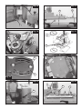
6396058
MANUAL DE INSTRUCCIONES
E
EB25
Modelo · Model · Modèle · Modell · Modello · Modelo
OPERATING INSTRUCTIONS USA GB
MODE D' EMPLOI
F
GEBRAUCHSANWEISUNG
D
MANUALE D'ISTRUZIONI
I
MANUAL DE INSTRUÇÕES
P
Aplacadora de Cantos Preencolados
Edgebander
Plaqueuse de Chants
Kantenleimmaschinen
Bordatrice
Orladora
MANUAL DE INSTRUCCIONES
OPERATING INSTRUCTIONS
MODE D'EMPLOI
GEBRAUCHSANWEISUNG
MANUALE D'ISTRUZIONI
MANUAL DE INSTRUÇÕES
página/page
seite/pagina
ESPAÑOL
ENGLISH
FRANÇAIS
DEUTSCH
ITALIANO
PORTUGUÉS
Fig. 1
Aplacadora de Cantos Preencolados EB25
EB25 Edgebander
Plaqueuse de Chants EB25
Kantenleimmaschinen EB25
Bordatrice EB25
Orladora EB25
5
8
11
14
17
20
Fig. 2
Fig. 3
2
Fig. 4
B
S
J
L
A
N1
K
R1
Fig. 5
Fig. 6
G
Fig. 7
H1
F
D
C
G1
H
E
Fig. 8
Fig. 9
J
K
Y
I
L
U
R
Fig. 11
Fig. 10
M
J1
N
P
3
Fig. 12
Fig. 13
X
S
X
V
Fig. 14
Fig. 15
CORTE 2
W
Z
CORTE 1
X1
A1
B1
C1
D1
C1
Fig. 16 bis
Fig. 16
Fig. 17
Fig. 18
K1
F1
4
L1
Fig. 19
M1
ESPAÑOL
APLACADORA DE CANTOS
PREENCOLADOS EB25
1. INSTRUCCIONES DE SEGURIDAD
PARA EL MANEJO DE LA APLACADORA
- ¡ATENCIÓN! Lea atentamente el FOLLETO DE
INSTRUCCIONES GENERALES DE SEGURIDAD,
que se adjunta con la documentación de la máquina.
- Asegúrese antes de enchufar la máquina, que la
tensión de alimentación, se corresponda con la indicada en la chapa características.
- Mantener siempre las manos alejadas de las áreas
de corte y las zonas de temperatura.
- Use siempre recambios originales VIRUTEX.
- No use nunca cuchillas defectuosas o en mal estado
de corte.
2. CARACTERÍSTICAS TÉCNICAS
Potencia absorbida..........................................3000W
Motor......................................50 Hz · opcional 60 Hz
Nivel de presión acústica continuo
equivalente ponderado...............................82,9 dB(A)
Grueso mínimo a cantear.................................11 mm
Grueso máximo a cantear................................50 mm
Regulación electrónica de la Temperatura......0-500°C
Velocidad de trabajo...................................4,2 m/min
Peso.................................................................117 Kg
3. EQUIPO ESTANDAR
Al abrir la caja de embalaje, encontrará en su interior
los elementos siguientes:
1. Aplacadora de cantos preencolados EB25
2. Cjto. soporte desplazable
3. Cjto. lateral derecho
4. Cjto. lateral izquierdo
5. Caja conteniendo:
- Cargador cinta
- Soporte cargador
- Cjto. prensor
- Prolongación enchufe
- Juego de llaves
6. Documentación.
4. DIMENSIONES APLACADORA
El espacio ocupado por la Aplacadora, está representado en la (Fig. 1).
5. ENSAMBLAJE Y PUESTA EN MARCHA
1. MONTAJE DE LOS LATERALES
SUPERIORES DEL MUEBLE
Cada lateral dispone de cuatro tornillos de M6x15 y
dos clavijas de situación, debiéndose proceder para
su montaje de la forma siguiente (Fig. 2):
- Sacar los cuatro tornillos A de la mesa, posicionar
el lateral P1 mediante las dos clavijas S1 con el lateral
de la mesa.
- Roscar en sus alojamientos de la mesa, los dos
tornillos superiores A de dicho lateral y dejar apretados definitivamente.
- Roscar los otros dos tornillos A inferiores.
- Nivelar el lateral con la mesa del mueble, mediante
una regla y hacer dicha regulación con los tornillos
T1, asegurando su regulación mediante su tuerca
correspondiente, Una vez realizada esta operación,
terminar de apretar los dos tornillos anteriores A.
- Seguir el mismo procedimiento para el otro lateral
de la máquina.
2. MONTAJE DEL SOPORTE CARGADOR (Fig. 3)
- Desenroscar los tornillos U1 de su alojamiento.
- Colocar el soporte W1 y fijar éste, mediante los
tornillos U1.
- Colocar el cargador cinta B comprobando que gire
libremente.
3. MONTAJE DEL SOPORTE DESPLAZABLE
Para montar este conjunto soporte desplazable se
procede de la forma siguiente (Fig. 4):
- Extraer de la guía soporte desplazable J, el tornillo
K que fija el turrión L en uno de sus extremos.
- Colocar el soporte desplazable S y volver a montar
5
comprobando su correcto engrane con todas las poleas dentadas. Tensar nuevamente la correa mediante el desplazamiento de la polea tensora con una
presión suficiente para que cuando esté en funcionamiento efectúe un buen arrastre.
17. NIVEL DE RUIDO
El ruido de ésta herramienta eléctrica, está medido
según ISO/DIS 230/5.
El nivel de ruidos en el puesto de trabajo puede
sobrepasar 85 dB(A). En este caso es necesario
tomar medidas de protección contra el ruido para el
usuario de la herramienta.
18. RECOMENDACIONES
Para cualquier manipulación de mantenimiento en la
máquina, desconectar ésta de la red eléctrica.
Conservar el cable de alimentación y el enchufe en
buenas condiciones.
Para obtener un buen recorte de la cinta preencolada,
debemos trabajar con las cuchillas limpias de cola y
bien afiladas.
También la máquina, debe encontrarse limpia de
cola y recortes de cinta, para evitar posibles atascos
en el desplazamiento efectuado por la cinta
preencolada.
La presión que efectúe el alimentador sobre la superficie de los tableros, debe ser la necesaria para el
arrastre de los mismos. Una presión en exceso,
provoca un deterioro anticipado de la correa de
arrastre.
También es conveniente, que la superficie de la
misma, esté limpia de restos de cola o de cuerpos
extraños, con el fin de obtener un perfecto arrastre.
Para la limpieza de las cuchillas, se recomienda la
utilización de nuestro CANTSPRAY (spray
antiadherente sin silicona).
18. GARANTÍA
Todas las máquinas VIRUTEX, tienen una garantía
válida de 12 meses a partir del día de su suministro,
quedando excluidas todas las manipulaciones o daños ocasionados por manejos inadecuados o por
desgaste natural de la máquina. Para cualquier reparación, dirigirse al Servicio Oficial de Asistencia Técnica VIRUTEX.
VIRUTEX se reserva el derecho de modificar sus
productos sin previo aviso.
ENGLISH
EB25 EDGEBANDER
1. SAFETY INSTRUCTIONS FOR
EDGEBANDER USE
- WARNING! Read the GENERAL SAFETY
INSTRUCTIONS LEAFLET, which is included in the
machine documentation, carefully.
8
- Before connecting to the mains ensure that the supply
voltage corresponds that shown on the specification
plate.
- Always keep hands away from the cutting zone and
hot areas.
- Always use original VIRUTEX spare parts.
- Never use damaged or worn blades.
2.TECHNICAL SPECIFICATIONS
Input Power.................................................3000 W
Motor................................50 Hz · optional 60 Hz
Equivalent measured continuous
acoustic pressure level.........................82.9 dB(A)
Min. edging thickness....................................11 mm
Max. edging thickness...............................50 mm
Electronic temperature control................0-500°C
Working speed.......................................4.2 m/min
Weight......................................................117 kg
3. STANDARD EQUIPMENT
On opening the box, you will find the following items
inside:
1. Edgebander EB25
2. Sliding support assembly
3. Right side assembly
4. Left side assembly
5. Box containing:
- Tape loader
- Loader mounting
- Clamp assembly
- Extension lead
- Set of keys
6. Documentation
4. EDGEBANDER MEASUREMENTS
The space occupied by the Edgebander is shown in
(Fig. 1).
5. ASSEMBLY AND START UP
1. MOUNTING OF UPPER SIDES OF MACHINE
Each side has four M6x15 screws and two locating
pegs. The following procedure should be followed for
mounting (Fig. 2):
- Remove the four screws A from the table and
position side P1 using the two pegs S1 against the
side of the table.
- Screw the two upper screws A of the above
mentioned side into the table and tighten fully.
- Screw in the two lower screws A.
- Level up the side with the machine table using a
ruler by adjusting the two studs D. Once this operation
is completed tighten up the two lower screws T1,
ensure that they are properly adjusted using the
corresponding nut. Once this operation is completed,
tighten up the two lower screws A.
- Follow this procedure for the other side of the
machine.
2. MOUNTING OF THE LOADER SUPPORT (Fig. 3)
- Unscrew the screws U1 from their positions.
- Position the support W1 and secure it using the
screws U1.
- Position the tape loader B, ensuring that it turns
freely.
3. MOUNTING OF THE SLIDING SUPPORT
In order to mount this sliding support assembly the
following procedure should be observed (Fig. 4):
- Remove from the sliding support guide J, screw K
which holds the peg L at one of its ends.
- Position the sliding support S and reassemble to its
previous state.
- Level the sliding support S with respect to the table
using a ruler and by adjusting screw K.
- Proceed in an identical manner with the other sliding
support guide.
- Check the correct sliding of the assembly inside
the guides.
4. DESCRIPTION AND START UP
The machine has a safety switch (on-off) A on its
right-hand side (Fig. 5).
This is to safeguard against unexpected start-ups as
well as a for connecting the machine and electrical
overload to the mains. This should be carried out by
means of an extension cable with conductor and
earth, using conductors suitable for a nominal
intensity of 16A.
Next to the loader B, (Fig. 5), are the machine
remaining controls (Fig. 6), which consist of an
emergency switch C, on-off switch for the heater F,
on-off switch for the feeder motor D, indicator light E
showing on-off status of the machine and a regulating
button G to adjust the temperature of the heater.
To start up the machine, press the green button R1
(Fig. 5) to supply voltage to the machine. Pilot E lights
up. Then flick heater switch F and feeder motor switch D to On. If the machine receives an electrical
overload, switch N1 will be deactivated, cutting off
the supply voltage. In order to re-establish supply, it
will first be necessary to flick thermal switch N1 and
repeat the above steps.
If the emergency switch is used, this immediately
deactivates all the machine functions, making it
necessary to reset this switch by turning it in the
direction f the arrow and to press the green start-up
switch (Fig. 5) in order to recommence work.
Place a roll of pre-glued tape in loader B (Fig. 5).
Its width must correspond to the thickness of the
board to be edged; we recommend using a tape 3
mm wider than the board's thickness in order to
achieve perfect trimming.
Place the pre-glued tape in the tape guide and adjust
the height of guides I (Fig. 8) to the width of the tape,
using knob J, which raises or lowers guide I, and
ensuring that the tape moves smoothly.
Move the tape manually to the cutting edge and place a panel on the table, supporting it on the front of
control box U (Fig. 9), and move it over the milled
roller to check that the tape is moving smoothly
between the guides.
If no obstacles are observed, move the tape back as
far as the cutting edge using knob K (Fig. 8), ensuring
that the tape is moving correctly against the panel.
Close the feeder and start the machine by pressing
the green on-off button R1 (Fig. 5).
6. TEMPERATURE CONTROL
Before carrying out this operation it is important to
take the precaution of checking that the tape is not in
front of the air outlet from the blower L, (Fig. 9) to
prevent it overheating and thus damaging the preglued tape. Start the heater by moving switch F (Fig. 6)
to position 1.
To raise the temperature more quickly, turn the
electronic control G, (Fig. 6) to number 9 on the control scale and watch the temperature rise quickly.
Once it has reached 300°C turn the knob to point 5
on the scale and once the needle has stopped
moving, the temperature can be adjusted to the
correct level for the pre-glued tape we are using.
7. STRAIGHT EDGING,
TRIMMING AND FLUSH CUTTING
The machine leaves the factory prepared for this type
of work and the only adjustments needed are for the
pre-glued tape width and the width between the
trimming blades for the panel to be banded (the
adjustment for pre-glued tape width has already been
explained in section 5. ASSEMBLY AND START UP).
To adjust the trimming blades and place them in
working position follow the instructions in the section
on 11. ADJUSTING THE BLADES (Fig. 10).
The minimum measurements of panels for this edging
work are the following:
Minimum width 102 mm and 175 mm minimum length.
8. REGULATING EXCESS TAPE AT REAR
When banding, if there is an excess or lack of preglued tape at the rear, the tape can be adjusted
moving lever M1 (Fig. 19) slightly to the right or left
according to the indication (+,-) on the machine.
9. CLAMP ASSEMBLY
The machine is equipped with two clamps X, (Fig.
13) fixed to the extension guide S, which push the
panel from the side of panel on rollers.
It is advisable to place clamp X on the left of the
extension guide S, i.e. at the feeder outlet, to ensure
correct trimming.
10. CHANGING THE TRIMMING BLADES
For ease of access to the motorised trimmer open
the feeder by loosening handle H, (Fig. 7).
Remove all of the protection devices which cover the
unit by removing the three screws Y on each side,
(Fig. 9).
Remove screws Z which secure the belts unit to pulley
W and remove the pulley, (Fig. 14).
Remove screws A1 which hold the blades in place,
9
(Fig. 15). Remove the blades.
The blades cut on both sides of the teeth (cuts 1 and
2) so that the second cut can be used before it is
necessary to change them, by placing the lower blade
in the upper mounting and vice versa, (Fig. 15).
WARNING! After carrying out any work inside the
Trimming Unit always replace the protection devices
in their original positions.
11. ADJUSTMENT OF THE TRIMMING BLADES
Using knob M raise the upper blade holder until the
panel can pass beneath it, (Fig. 10).
Insert the panel between the four supporting rollers
N, until it touches the shoe P on the blade holder.
Check that the lower blade holder rollers raise the
panel slightly above guides R, (Fig. 9). Using knob M
lower the upper blade holder until the panel is sitting
on the guides R. The trimmer is now ready for work.
12. ADJUSTMENT OF THE EXTENSION GUIDE
1. Loosen knobs T, (Fig. 1) and place the machine
extension guide S, (Fig. 13), in such a position that
the panel is well supported on guides R, (Fig. 9)
touching the front U (Fig. 9) on the control box.
2. Push the wood forward until it is picked up by the
feeder, at which point we can let it go, as it is guided
with sufficient pressure to stick the pre-glued tape to
the edge.
3. As the panel moves through the machine, it goes
through the motorised trimmer where the excess tape
is trimmed off from both sides of the panel.
4. After this process the panel is moved on and as it
leaves the feeder it is pressed against a blade V,
(Fig. 12), which cuts off any remaining excess preglued tape.
5. The final product is a panel on which the pre-glued
tape has all been trimmed and the edges are flush
cut.
13. CHANGING THE TRIMMER BELTS
Remove the protective devices which cover the unit
by removing the three screws Y from each side, (Fig.
9).
Remove the used toothed belt and replace it with a
new VIRUTEX original spare lining it up correctly with
the teeth on the pulley without forcing it, (Fig. 14).
14. CHANGING THE TRIMMER BRUSHES
Disconneet the connection cable of the motorised
trimmer.
Remove the motorised trimmer from its housing in
the machine, loosening screws X1 (Fig. 14).
Remove screws B1 from the protector D1, removing
the latter from its housing and cover (Fig. 16).
Raise springs C1 (Fig. 16 bis) which hold the brushes
in place and replace the brushes with VIRUTEX original spares, ensuring that they move smoothly inside
the guides.
Replace the cap D1.
It is recommendable to leave the trimmer running for
10
10 minutes without working to shape the brushes
better.
If any roughness or damage is observed on the
collector, we recommend you have it repaired at a
VIRUTEX service point.
Never use sandpaper for this operation.
15. ADJUSTMENT OF THE FEEDER
Loosen the handles F1 and G1, (Fig. 17 and 7).
Position the feeder index to the measurement
corresponding to the thickness of the panel by turning
the wheel H1, (Fig. 7).
Tighten the handles F1 and G1, (Fig. 17 and 7).
Open the feeder using handle H, (Fig. 7) in order to
see the height of the trimmer blades, and adjust the
height if necessary, (section 11. ADJUSTMENT OF
THE TRIMMING BLADES). The lamp E, (Fig. 6) on
the indicator panel when opening the feeder.
Once the trimmer blades have been adjusted close
the feeder using handle H, (Fig. 7), leaving a slight
angle with respect to the rollers on which the panel
moves. Thus, when the feeder is operating the panel
will always be pressed against the corresponding
rollers when it is being pulled through the machine.
Press safety switch R1, (Fig. 5), to connect the current
to the machine.
16. CHANGING THE BELT
Remove the three screws J1, (Fig. 11) and take off
the cover. Loosen the tensor pulley K1 and slacken
the belt if necessary, (Fig. 18). Replace the belt L1
with another original VIRUTEX, checking that it
correctly meshes with all the toothed pulleys.
Tension the belt by sliding the tensor pulley in order
that it gives a good drag when in service.
17. NOISE LEVEL
The noise generated by this electrical machine is
measured according to ISO/DIS 230/5.
The noise level in the workplace could exceed
85dB(A). In this case the necessary precautions
against noise should be taken by the user of the
equipment.
18. RECOMMENDATIONS
For any work involving handling of the machine,
disconnect from the mains. Maintain the supply cable and plug in good condition. In order to obtain a
good cut of the tape we should always work with
sharp, glue-free blades.
The machine must also be kept clean and free of
glue and tape cuttings in order to avoid the pre-glued
tape becoming jammed.
The pressure the feeder exerts on the surface of the
panels through the machine as excess pressure will
cause increased wear on the feed belt.
It is also recommended that the surface of the belt
be kept clean and free of glue and foreign bodies in
order to obtain perfect pulling of the panels.
For cleaning the blades, we recommend use of our
CANTSPRAY (nonadherent silicone-free spray).
la (Fig. 1).
19. GUARANTEE
All VIRUTEX machines are guaranteed for 12 months
from the date of supply, excluding any damage which
is a result of incorrect use or of natural wear and tear
on the machine. All repairs should be carried out by
the official VIRUTEX technical assistance service.
5. ASSEMBLAGE ET MISE EN MARCHE
1. MONTAGE DES PANNEAUX
LATÉRAUX SUPÉRIEURS DU MEUBLE.
Chaque panneau latéral dispose de quatre vis de
M6x15 et de deux clavettes de situation, le montage
devant être effectué de la façon suivante (Fig. 2):
- Retirer les quatre vis A de la table, positionner le
panneau latéral P1 à l'aide des deux clavettes S1
sur le côté de la table.
- Visser les deux vis supérieures A de ce panneau
dans leurs logements de la table et les serrer
définitivement.
- Visser les deux autres vis A inférieures.
- Niveler le panneau latéral avec la table du meuble
à l'aide d'une règle et faire le réglage avec les vis T1,
assurant son réglage à l'aide de leur écrou
correspondant. Après avoir réalisé cette opération,
terminer de visser les deux vis antérieures A.
- Suivre le même procédé pour l'autre panneau latéral
de la machine.
VIRUTEX reserves the right to modify its products
without prior notice.
FRANÇAIS
PLAQUEUSE DE CHANTS EB25
1. INSTRUCTIONS DE SÉCURITÉ POUR
LE MANIEMENT DE LA PLAQUEUSE.
- ATTENTION! Lire attentivement la BROCHURE
D’INSTRUCTIONS GÉNÉRALES DE SÉCURITÉ,
jointe à la documentation de la machine.
- Avant de brancher la machine, s'assurer que la
tension d'alimentation correspond à celle indiquée
sur la plaque des caractéristiques.
- Maintenir toujours les mains éloignées des zones
de coupe et des zones de température.
- Utiliser toujours des pièces de rechange d'origine
VIRUTEX.
- Ne jamais utiliser de couteaux défectueux ou en
mauvais état.
2. CARACTÉRISTIQUES TECHNIQUES
Puissance absorbée.......................................3000 W
Moteur................................50 Hz · en option 60 Hz
Niveau de pression acoustique continu
équivalent pondéré....................................82,9 dB (A)
Largeur minimum..............................................11 mm
Largeur maximum.........................................50 mm
Réglage électronique de la température.........0-500°C
Vitesse de travail....................................4,2 m/min
Poids.............................................................117 kg
3. ÉQUIPEMENT STANDARD
Dans la caisse d'emballage, vous trouverez les pièces
suivantes:
1. Plaqueuse de chants EB25
2. Ens. support déplaçable
3. Ens. panneau latéral droit
4. Ens. panneau latéral gauche
5. Caisse contenant:
- Chargeur bande
- Support chargeur
- Ens. presseur
- Rallonge prise
- Jeu de clés
6. Documentation
4. DIMENSIONS DE LA PLAQUEUSE
L'espace occupé par la plaqueuse est représenté sur
2. MONTAGE DU SUPPORT CHARGEUR (Fig. 3)
- Dévisser les vis U1 de leur logement.
- Placer le support W1 et le fixer, à l'aide des vis U1.
- Placer le chargeur de bande B en vérifiant qu'il
tourne librement.
3. MONTAGE DU SUPPORT DÉPLAÇABLE
Pour monter cet ensemble support déplaçable, on
procède de la façon suivante (Fig. 4):
- Retirer du guidage support déplaçable J, la vis K
qui fixe le tourillon L à l'une de ses extrémités.
- Placer le support déplaçable S et le remonter
comme il était.
- Niveler avec une règle le support déplaçable S par
rapport à la table à l'aide de la vis K.
- Procéder de la même manière avec l'autre guidage
support déplaçable.
- Vérifier le déplacement correct de l'ensemble dans
les guidages.
4. DESCRIPTION ET MISE EN MARCHE
La machine dispose d'un interrupteur de sécurité
(marche-arrêt) A, sur le côté droit (Fig. 5).
Cet interrupteur sert de protection contre les
démarrages intempestifs de la machine, contre
surcharges de courant et également, de prise de
courant pour brancher la machine sur le secteur, ce
branchement devant être réalisé à l'aide d'une
rallonge pourvue d'un conducteur et d'une prise de
terre et avec les conducteurs appropriés pour une
intensité nominale de 16 A.
Près du chargeur B, (Fig. 5), se trouve le reste des
commandes de la machine, (Fig. 6), celle-ci étant
pourvue d'un interrupteur d'arrêt d'urgence C, un
interrupteur de mise en marche et arrêt du radiateur
F, un interrupteur de mise en marche et arrêt du
moteur poutre d'entraînement D, un voyant lumineux
11