1
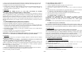
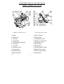
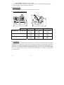
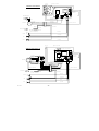
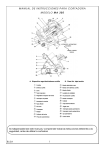
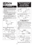
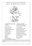
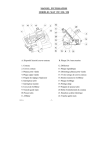
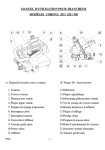
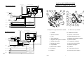
MANUAL DE INSTRUCCIONES
ENCHUFE
verde-amarillo
MODELOS CORONA 292 / 320 / 350
TR2
RL1
TYPE 55.12
10A-250V
20 A 24
2,8 VA
24 V
K M GND
ESQUEMA ELECTRICO II
verdeamarillo
+
V S
R U
CONDENSADOR
marrón
azul
rojo
rojo
1
10
11
2
marrón
negro 4
22
17
verde-amarillo
20
~
azul
16
8
18
4
negro 1
negro 2
blanco
negro
230 v.
50 y 60 Hz. v e r d e - a m a r i l l o
M
MOTOR
19
9
DCBA
negro 3
3
12
IMAN
SENSOR DEFENSA CUCHILLA
(Para modelos CE)
24 V.
L A M P A R A 2 W.
3
A
naranja
MARCHA
rojo
4
2
PARO
14
15
marrón
B
5
13
6
21
7
amarillo
1
ENCHUFE
ESQUEMA ELECTRICO III
A. Dispositivo seguridad defensa cuchilla
verde-amarillo
B
CAMBIO DE VOLTAJE
K M GND
230V 400V
M
230/400 V.
50 y 60 Hz.
~
DCBA
MOT.
blanco
rojo
violeta
400
blanco
negro
azul
marrón
azul
negro
negro 1
negro 2
negro 5
verde-amarillo
azul
IMAN
marrón
negro 4
SENSOR DEFENSA CUCHILLA
(Para modelos CE)
negro 3
marrón
24 V.
L A M P A R A 2 W.
naranja
3
MARCHA
BISA
10A-250V
TYPE 55.13
R U T W V S
230
verde-amarillo
PARO
TR2
-
MOTOR
A
negro
verde
azul
verdeamarillo
+
RL1
rojo
4
2
1. Cuchilla
12. Deflector de loncha
2. Defensa cuchilla
13. Placa de características
3. Carro
14. Mando abatimiento carro
4. Tope de gruesos
15. Mando cierre defensa cuchilla
5. Regulador del espesor de loncha
16. Mando afilador
6. Pulsador de parada
17. Lengüeta de rebabado
7. Pulsador de marcha
18. Aro protección cuchilla
8. Tapa afilador
19. Mando contrapeso
9. Protector de los dedos
20. Cabezal
10. Contrapeso
21. Tapa sistema eléctrico
11. Afilador
22. Protector para las manos
amarillo
1
B. Placa 24v. baja tensión
8
BISA
1
1.-DESCRIPCION DE LA MAQUINA
La máquina es una cortadora de gravedad que se utiliza principalmente para cortar fiambres.
Su principal elemento es la cuchilla (1) que gira sobre su propio eje mediante la energía
suministrada por el motor con una transmisión directa.
2.-INSTRUCCIONES DE SEGURIDAD
La máquina está equipada con dispositivos de seguridad para la prevención de accidentes:
2.1.-DISPOSITIVOS ELECTRICOS:
1. Los pulsadores (6-7) y los dispositivos de seguridad (A-B) trabajan a baja tensión.
2. Cuando se reinstaura la corriente eléctrica, después de una interrupción de suministro, la
máquina no se pone en marcha automáticamente, es necesario presionar el pulsador de
marcha (6) para que se ponga en funcionamiento.
3. Los cables de toma de tierra, de color verde y amarillo, tienen la misma sección que los
cables con mayor sección de la máquina.
4. Los componentes eléctricos situados en el interior de la máquina están protegidos de acuerdo
a IP33. Los situados en el exterior de la máquina están protegidos de acuerdo a IP65.
5. Si se desmonta la defensa cuchilla (2), la máquina no se puede poner en marcha. (modelos CE)
2.2.-DISPOSITIVOS MECANICOS:
1. El filo de la cuchilla está protegido por un aro fijo (18) en la zona de la cuchilla no prevista
para el corte del producto, que lo cubre al menos 2 mm. tanto en la parte anterior como
posterior.
2.Protector de ABS (9) con un pliegue (protector del pulgar), cubre el filo de la cuchilla al
menos 10 mm. cuando el carro está en su posición más avanzada al final de la operación de
corte.
3. Protector de acero inoxidable (22), evita que la mano llegue directamente al filo de la
cuchilla. ( modelos CE )
4. No es posible abatir el carro a no ser que el regulador de espesor de loncha se encuentre en
la posición cero y el carro esté en su posición más retrasada. ( modelos CE )
2.3.-SIMBOLOS
Es obligatorio leer todo el manual de instrucciones antes de realizar
ninguna operación en la máquina.
ATENCION: Antes de conectar la máquina a la red consultar siempre la placa de
características (13), ya que el voltaje señalado arriba puede variar cuando la máquina va
destinada a países con voltajes diferentes.
Seguridad:
1. Placa 24v. baja tensión, aro fijo guarda cuchilla, pulsadores de marcha parada, no puesta
en marcha involuntaria de la máquina tras un corte de corriente y protector para las manos.
2. Sistema de seguridad para el abatimiento del carro y en la defensa cuchilla en los modelos
CE .
Acabado: Acero inoxidable pulido y aluminio anodizado.
Transmisión: Sinfín/corona.
MOD.
Diámetro de cuchilla
Capacidad de corte en redondo, mm
Capacidad de corte rectangular, mm
Capacidad de corte en cuadrado,
mm.
Espesor de corte, mm
Peso neto, Kg.
292
292
200
270 x
160
180
0 - 25
42
320
320
220
280 x
170
195
0 - 25
45
350
350
230
315 x 180
200
0 - 25
47
13.- ANEXO PARA SERVICIO TECNICO: CAMBIO DE VOLTAJE EN TRIFASICO
Para cambiar de 400v. a 230v. o de 230v. a 400v., deben realizarse dos operaciones:
1. En la salida del motor sustituir el conector que indica 400v. por el de 230v. o viceversa según
el voltaje deseado. Ver detalle A en el esquema eléctrico trifásico (Pág. 8). Este conector se
encuentra en la parte inferior de la máquina según se indica en el gráfico de esta página.
2. Soltar la tapa sistema eléctrico (21) y cambiar en la placa eléctrica de 24v. el conector
de 400v. a 230v. o viceversa según el voltaje deseado. Ver detalle B en el esquema eléctrico
trifásico (Pág. 8). Una vez realizada la operación, volver a colocar la tapa sistema eléctrico
(21) en su posición inicial.
MUY IMPORTANTE: Tanto el motor como la placa eléctrica deben estar conectadas
al mismo voltaje.
Después del cambio, el nuevo voltaje debe aparecer marcado en vez del antiguo en la placa
de características de la máquina (13).
Máquina conforme a la Directiva Europea 89/392/CE, 91/368/CE, 93/44/CE,
93/68/CE, 98/37/CE (los modelos vendidos en la Comunidad Europea).
No utilizar agua a presión para limpiar la máquina.
BISA
2
BISA
7
8.4.-Problema: No se logra un buen afilado de la cuchilla.
1. Comprobar que la piedra de afilar no esté desgastada o sucia, en cuyo caso habría que
reemplazarla.
2. Puede que la cuchilla esté muy desgastada, si es así, avise al distribuidor autorizado para su
sustitución.
9.-NIVEL ACUSTICO
La máquina mantiene un nivel acústico por debajo de los 70 decibelios (A).
C
10.- DIMENSIONES GENERALES DE LA MAQUINA
A1
B1
B2
A2
A3
Dimensiones
Instalación
Trabajo
B3
mm.
A1 x B1 x C
A2 x B2 x C
A2 x B3 x C
292
515 x 340 x 510
705 x 570 x 510
735 x 715 x 510
320
535 x 340 x 520
735 x 570 x 520
755 x 715 x 510
350
555 x 340 x 530
765 x 570 x 530
785 x 715 x 530
11.- RESPONSABILIDAD
No será aceptada ninguna responsabilidad en caso de daños debidos a uso inadecuado, manejo
defectuoso, modificaciones estructurales, supresión de elementos protectores o uso de repuestos y
otros accesorios que no sean los originales del fabricante. El vendedor no se responsabilizará hacia
el comprador por defectos ocasionados por el desgaste natural de la máquina.
12.- CARACTERISTICAS TECNICAS
Motor..............: M:
T:
BISA
0’242 Kw.
0’242 Kw.
230 v.
50 Hz. 1 Ph.
230/400 v. 50 Hz. 3 Ph.
6
3.-INSTALACION
3.1.-INSTALACION EN EL LUGAR DE TRABAJO
La cortadora debe estar instalada sobre un soporte estable y liso
respetando la altura de instalación indicada en la figura adjunta.
Asegurarse de que el soporte podrá aguantar el peso de la máquina. Ver
el capítulo 10 para saber el espacio requerido para su instalación.
ATENCION: La cortadora es pesada. Son necesarias dos personas para
trasladarla, agarrándola por los puntos señalados con flechas en la figura
del capítulo 10.
900 mm.
8.3.-Problema: No se consigue un corte bueno y uniforme.
1. Comprobar que la cuchilla esté bien afilada. Si no es así, proceder a su afilado según lo
indicado en el apartado 5 de este manual.
2. El tope (4) puede no estar bien alineado con la cuchilla (1). En este caso, avisar al
distribuidor autorizado.
3.2.-CONEXION A LA RED ELECTRICA ¡ATENCION!
1. Asegurarse de que el voltaje del suministrador principal coincide con el que se indica
en la placa de características de la máquina (13).
2. La base del enchufe debe estar a una altura del suelo entre 0’6 m y 1’9 m, y debe quedar a
la vista del usuario para que pueda verificar que la máquina está desenchufada antes de
proceder a su limpieza.
3. La máquina ha de conectarse siempre a una base de enchufe con toma de tierra.
4. No conectar ni hacer funcionar la máquina si el cable o el enchufe están dañados.
5. El fusible de la base del enchufe será de una intensidad entre 3 y 6 amperios.
6. La máquina debe estar conectada a un diferencial.
7. En el caso del modelo de 3Ph., si se requiere un cambio de voltaje de 400v. a 230v. o
viceversa, consultar el apartado 13.
8. En los modelos de 3Ph. hay que verificar que el sentido de giro sea el correcto, o sea, en el
sentido contrario a las agujas de reloj, tal y como indica la flecha situada en el afilador (11); si
no fuera así, intercambie dos de las fases del enchufe para cambiar el sentido de giro.
4.-UTILIZACION ¡ATENCION!
1. Para colocar o retirar el producto del carro (3), la máquina debe estar siempre parada y el
regulador de espesor de loncha (5) en posición cero.
2. No introducir nunca las manos en la zona de corte. Para sujetar el producto, utilizar el
contrapeso (10) agarrándolo por su empuñadura (19).
3. No tocar nunca la cuchilla (1); tanto si está en movimiento como si estuviera parada.
4. Dejar siempre el regulador de espesor de loncha (5) en posición cero tras su utilización.
5. Mantener las manos, ropa y cabellos alejados de todas las partes móviles de la máquina.
6. Apagar siempre la máquina cuando no se utilice.
7. Condiciones de utilización: Temperatura: 5 - 40º C / Humedad: 30 - 95%.
La cortadora le permitirá cortar fiambres, carnes, salchichas, etc. No se deben cortar productos
congelados, ni productos no comestibles. Antes de proceder al corte, retirar los envoltorios y
precintos que puedan llevar estos productos, ya que deterioran el filo de la cuchilla y su duración.
4.1.-OPERACION DE CORTE:
Para colocar el producto a cortar, levantando el contrapeso (10), depositar la pieza sobre el
carro (3) de forma que la zona a cortar esté apoyada en el tope (4).
BISA
3
1. Elegir el espesor de loncha deseado maniobrando el mando de regulación (5) de 0 a 25 mm.
2. Presionar sobre el pulsador de marcha (7). El piloto se enciende y la cuchilla empieza a rotar.
3. Empujar el carro (3), en movimiento de ida y vuelta.
4. Cuando tenga el número de lonchas deseadas, presione sobre el pulsador de parada rojo (6),
la cuchilla se para. Como medida de seguridad, volver a colocar el mando regulador de
espesor de loncha (5) en posición cero.
5.-AFILADO
ATENCION: NO ABRIR NUNCA LA TAPA DEL AFILADOR SIN HABER
DESCONECTADO Y DESENCHUFADO LA CORTADORA.
La calidad de afilado de la cuchilla le garantizará un corte perfecto de sus productos y ahorrará
esfuerzos suplementarios al motor. Antes del afilado, es conveniente limpiar el filo de la cuchilla
de toda película de grasa ocasionada por el corte de los productos. En caso contrario, esas
partículas de grasa se quedan en el grano de la piedra y ésta se vuelve inoperante. Afilar la
cuchilla siempre que sea necesario. Es aconsejable afilar ligeramente por lo menos una vez al
día como mantenimiento, para conseguir una mejor conservación del filo y una mayor vida de la
cuchilla.
5.1.-PROCEDIMIENTO PARA AFILAR LA CUCHILLA:
1. Colocar el regulador de espesor de loncha (5) en posición cero.
2. Presionar el pulsador de marcha (7) para que la cuchilla comience a rotar.
3. Presionar y girar suavemente con la mano el mando del afilador (16) hasta que la piedra entre
en contacto con la cuchilla. Mantener una ligera presión hasta que se considere que el filo es
el adecuado. Soltar el mando que volverá a su posición inicial.
4. Para rebabar, accionar el mando (17) hasta que el rebabador contacte con la cuchilla durante
solamente un segundo.
5. Presionar el pulsador rojo (6) para parar la rotación de la cuchilla.
6. Proceder a la limpieza de la máquina (ver capítulo 6).
ATENCION: La cuchilla debe ser cambiada cuando la distancia entre el filo y el aro protector (18)
sea superior a 6 mm. El cambio de la cuchilla debe realizarse por personal cualificado.
6.-LIMPIEZA
Después del uso diario hay que limpiar la máquina, además es necesario tener la cortadora
lubricada (ver capítulo 7).
ATENCION: Antes de toda limpieza y mantenimiento, desconectar la cortadora de la
red y poner el regulador de espesor de loncha (5) en posición cero.
Para su limpieza, todas las superficies sobre las cuales pueden acumularse desechos del
producto son fácilmente accesibles tras un cómodo desmontaje de algunos elementos. Utilice un
trapo humedecido en una solución de agua enjabonada. No utilice productos químicos,
disolventes ni abrasivos. Aclarar y secar.
6.1.-DESMONTAJE DE LA DEFENSA-CUCHILLA (2):
1. Desenroscar manualmente el mando de cierre (15) situado en el cabezal (20) de la máquina.
2. Levantar con cuidado la defensa cuchilla (2) utilizando las dos manos.
3. Para el montaje, proceder inversamente.
BISA
4
6.2.-ABATIMIENTO DEL CARRO (3):
1. Retirar el producto del carro (3).
2. Colocar el regulador de espesor de loncha (5) en posición cero.
3. Colocar el carro (3) en la posición más retrasada.
4. Desenroscar el mando soporte carro (14) y abatir el carro (3) hacia el exterior para la
limpieza.
5. Para colocar el carro (3) nuevamente en su posición de trabajo, proceder inversamente.
1.
2.
6.3.-DESMONTAJE DEL DEFLECTOR DE LONCHAS (12):
Tirar de él hacia arriba con las manos, haciéndolo rotar ligeramente sobre su eje.
Para el montaje, proceder en sentido inverso.
6.4.-LIMPIEZA DE LA CUCHILLA (1):
1. IMPORTANTE ADVERTENCIA: Esta operación es peligrosa, extreme las
precauciones y no toque nunca el filo de la cuchilla; verifique previamente que el
regulador de espesor de loncha (5) está en la posición cero y utilice guantes de
protección.
2. Limpiarla con un trapo humedecido desde el centro hacia el exterior de la misma.
6.5.-FRECUENCIA DE LA LIMPIEZA:
Para garantizar una máxima higiene, aconsejamos limpiar todos los días las partes o piezas
directamente en contacto con los productos alimenticios. Limpieza completa de la máquina: una
vez por semana. Una vez haya montado la máquina tras la limpieza, cúbrala con una tela limpia.
7.-LUBRICACION
ATENCION: Desconectar la cortadora antes de efectuar esta operación.
Antes de lubricar la cortadora, limpiar y secar todas las áreas que lo necesitan. Utilizar aceite ISO
VG 15, aceite mineral blanco (por ejemplo ENERGIOL WM2-BP). No utilizar aceite vegetal.
Cada semana aproximadamente es necesario lubricar los siguientes elementos: la barra guía
contrapeso y, por debajo de la base de la máquina, la barra deslizante del carro.
Periódicamente será necesario lubricar las siguientes áreas por debajo de la base de la cortadora: la
leva del regulador de espesor de loncha, además del mando y el eje regulador de la cuchilla.
8.-POSIBLES IRREGULARIDADES
8.1.-Problema: La cortadora no se pone en marcha.
1. Comprobar si hay corriente en la base del enchufe.
2. Comprobar que el voltaje de la base del enchufe coincide con el de la placa de
características de la máquina (13).
3. Si los apartados anteriores son correctos, avisar al distribuidor autorizado.
8.2.-Problema: Comienzo lento del motor o recalentamiento.
1. Comprobar que el voltaje de la base del enchufe coincide con el de la placa de
características de la máquina (13).
2. Si es correcto, avisar al distribuidor autorizado.
BISA
5
OPERATORS MANUAL FOR THE SLICER
MODEL CORONA 292 / 320 / 350
9
19
1
10
4
11
2
8
18
17
16
22
20
3
12
14
15
A
B
A. Blade cover safety device
5
13
6
21
7
B. Low tension 24v. plate
1. Blade
12. Slicer deflector
2. Blade cover
13. Rating plate
3. Carriage
14. Carriage lock knob
4. Gauge plate
15. Blade cover lock knob
5. Slice thickness regulator
16. Sharpener knob
6. Off switch
17. Burr tongue
7. On switch
18. Blade guard
8. Sharpener cover
19. Product pusher handle
9. Finger guard
20. Blade drive housing
10. Product pusher
21. Electric system cover
11. Blade sharpener
22. Hand guard
B.I.S.A.
-1-
1.-MACHINE DESCRIPTION
The machine is a gravity slicer. This machine is used for cutting cold meat. Its main element
is a round knife (1), which turns around with rotation over its own axle. A motor supplies the
energy for this rotation by crown drive.
2.-SAFETY INSTRUCTIONS
The machine is equipped with some safety devices in order to prevent hazards.
2.1.-ELECTRICAL DEVICES:
1. The push buttons (6-7) and the safety devices are working on low tension.
2. When the power is restored after a power interruption or when an interlock switch is remade
the machine does not automatically start. It is necessary to restart the machine by pressing
the on switch (6).
3. The machine is grounded with green/yellow coloured wires which have the same section of
the wires with bigger section of the machine.
4. The electrical components situated inside the machine housing are protected according to IP33
and the electrical components situated outside are according to IP65.
5. If the cover blade (2) is lift up, the machine cannot restart. (Models CE)
2.2.-MECHANICAL DEVICES:
1. A blade guard (18), with 2 mm. at least, protects the blade edge, at both sides back and front,
at the no cutting area.
2. ABS guard (9) with a bend (thumb guard), covers the blade edge at least 10mm, whenever
the carriage is at its most advanced position at the end of the cutting operation
3. There is a stainless steel guard (22), that avoids the hand to arrive in a frontal direction to the
blade edge. (Models CE)
4. It is only possible to tilt the carriage when the slice thickness regulator is in the zero position
and the carriage is in the backward position. (Models CE)
2.3.-SYMBOLS:
It is obligatory to read the entire instructions manual before any
operating on the machine.
Machine according to the Directive 89/392/EEC, 91/368/EEC,
93/44/EEC, 93/68/EEC, 98/37/CE (The models sold at the
European Community).
Do not use a jet water source for cleaning the machine.
B.I.S.A.
-2-
900 mm.
3.-INSTALLATION
3.1. INSTALLATION ON THE WORKPLACE
The slicer should be installed on a work surface that has sufficient
stability and strength to support the weight of the machine, and always
maintaining the appropriate height from the floor, as shown in the
figure. See section 10 for working area necessary.
CAUTION: The slicer is heavy. Two persons are required when
lifting or moving it. The machine must be hold by the points indicated
at the figure of section 10
3.2.-ELECTRICAL CONNECTION
WARNING
1. Make sure that the line voltage of your main power source matches the rated voltage of
the machine shown at the rating plate (13).
2. Do not turn on the slicer if the cord or plug is damaged.
3. Always plug the machine to a grounded outlet.
4. The fuse in the outlet plug must have between 3 and 6 amperes.
5. The outlet plug should remain at a height from the floor in between 0,6 or 1,9 m., and should
remain at sight in a way to be seen by the user.
6. At three-phase models, if it is necessary a change of voltage, see section 13.
7. The machine must be connected to a leakage current breaker.
8. At three-phase models, it is necessary to check the sense of rotation as the correct one, so
that it should be the opposite sense as of the clock, as shown in the signals of the sharpener
device (11); if this is not correct, there should be a change made to the phases of the plug in
order to change the sense of rotation.
WARNING
4.-OPERATION
1. Before removing the product from the carriage (3), the machine ought to be turned off and
the slice thickness regulator (5) in the zero position.
2. Always keep hands away from the blade zone and use the product pusher (10) or carriage
handle (19) when slicing the product.
3. To avoid accidents, NEVER touch the edge of the blade (1), and NEVER touch any part of
the blade if the blade is rotating.
4. Always leave the slice thickness dial (5) set at zero after using the machine.
5. Always keep hands, hair and clothing away from all moving parts.
6. Always turn off the machine when not in use.
7. Operating conditions: Temperature: 5-40ºC / Humidity: 30-95%.
The slicer will allow you to cut deli products, meat, sausage, etc. Do not slice frozen products,
bones and no comestible products. Before attempting the use of the machine, remove the
wrapped and sealed parts so that the edge of the blade will not get damaged.
4.1.-SLICING THE PRODUCT
1. Lift the product pusher (10) and place the product on the carriage (3) so that the face of the
product to slice is resting on the gauge plate (4).
B.I.S.A.
-3-
2.
3.
4.
5.
Adjust the slice thickness turning the slice thickness regulator (5) from 0 to 25 mm.
Pressing the On switch (7), blade starts to rotate.
Push the carriage (3) forward and back over the blade with a continuous motion.
After slicing the desired amount of the product, press the Off switch (6) to stop the slicer.
Then, make sure to turn the slice thickness regulator (5) to “0” position.
5.-BLADE SHARPENING
WARNING: NEVER LIFT UP THE SHARPENER COVER IF THE MACHINE HAS
NOT BEEN DESCONNECTED OR UNPLUGGED BEFORE.
The sharpening quality of the blade will guarantee a much longer life of the blade, a perfect
cutting slice and this will avoid extra efforts for the motor. Before sharpening, make sure that
the blade is completely clean and grease free. The sharpening procedure should be performed at
least once a day to keep the cutting edge sharp and last longer.
5.1.-PROCEDURE FOR BLADE SHARPENING
1. Place the thickness regulator (5) in “0” position.
2. Press the green switch (7) on so that the blade starts rotating.
3. Press and turn carefully with your hand the sharpener knob (16) to your right until the stone
gets in contact with the edge of the blade.
4. To burr the blade, pull the burr tongue (17) for 1 second. It is very important to follow this
operation carefully to preserve the edge and the life time of the blade.
5. Press the off switch (6) to stop the blade rotation.
6. Follow section 6 for cleaning procedures of the machine.
WARNING: The blade has to be replaced when the gap between the edge and the blade guard
(18) exceeds 6 mm. Only qualified personnel should do the change of blade.
6.-MAINTENANCE AND CLEANING
Clean the slicer after every daily use. Also make sure that the slicer is sufficiently lubricated
(see section 7).
WARNING: Always turn off the machine before cleaning and make sure to turn the slice
thickness dial (5) to “0” position.
All the surfaces are very easy for cleaning from food waste and easy for removing the
different parts. Always use a damp cloth in detergent to clean the machine. Never use any
chemical or abrasive products.
6.1.-BLADE COVER DISASSEMBLY (2):
1. Unscrew the blade cover lock knob (15) placed in the back of the blade drive housing (20).
2. Grasp the blade cover (2) with both hands very carefully. Clean and dry the blade cover.
3. To reassemble, proceed inversely.
B.I.S.A.
-4-
1.
2.
3.
4.
5.
6.2.-SWINGING OF THE CARRIAGE (3):
Remove any product from the carriage.
Turn the slice thickness regulator (5) to “0” position.
Move the carriage (3) to a backward position..
Unscrew the carriage lock knob (14) and tilt the product carriage out, .for cleaning purposes.
In order to place the carriage (3) to its original position, proceed inversely.
6.3.-SLICE DEFLECTOR DISASSEMBLY (12):
1. Lift up the deflector with the hands, by rotation carefully on its own axle.
2. To reassemble, proceed inversely.
6.4.-BLADE CLEANING (1):
1. IMPORTANT WARNING: This is a dangerous operation, extreme precautions Do not
touch the edge of the blade. Make sure to turn the slice thickness regulator (5) to “0”
position. Wear a safety glove.
2. Clean the blade with a damp cloth. Wipe only from the centre of the blade toward the outer edge.
6.5.-CLEANING FREQUENCY:
To guarantee a maximum hygiene level, it is necessary to clean all the parts in the contact
food area every day. Make sure to clean the machine completely at least once a week. Cover the
machine with a clean cloth once you have finished cleaning the slicer.
7.-LUBRICATING
WARNING: Turn off the slicer before attempting this operation.
Before lubricating the slicer, clean and dry all the areas needed. Use a ISO VG 15 oil, white
mineral oil (for example, ENERGIOL WM2-BP). Do not use vegetable oil.
Approximately every week, it is necessary to lubricate the following elements:
Product pusher rail guide and, underneath the slicer, the carriage rail guide.
Periodically, it is necessary to lubricate the following areas: Underneath the slicer, the cam
which regulates the blade, the blade regulator knob and the axle regulating the blade.
8.-TROUBLE SHOOTING
8.1.-Problem: The slicer does not start.
1. Check if there is current at the plug base.
2. Verify the plug voltage is the same as the characteristics plate of the machine (13).
3. If these two points are correct, call the distributor authorised.
8.2.-Problem: A slow start engine or overheat.
1. Verify the plug voltage is the same as the characteristics plate of the machine (13).
2. If this is correct, call the distributor authorised.
8.3.-Problem: Product is not properly cut. Tail on uncut product.
1. Verify the sharpness of the blade. If this is not correct, proceed to sharpen the blade as
section 5 of this instruction manual.
2. Incorrectly line up of the gauge plate. Call the distributor authorised.
B.I.S.A.
-5-
8.4.-Problem: Blade does not cut enough.
1. Verify that the stones are not worn out or dirty. In this case replace the sharpening stones.
2. Worn out blade. Call the distributor authorised.
9.-SOUND LEVEL
The slicer maintains an acoustic level under the 70 decibels (A).
C
10.-SLICER MEASUREMENTS
A1
B1
B2
A2
A3
Dimensions
Installation
Working
B3
mm.
292
A1 x B1 x C 515 x 340 x
510
A2 x B2 x C 705 x 570 x
510
A3 x B3 x C 735 x 715 x
510
320
535 x 340 x
520
735 x 570 x
520
755 x 715 x
510
350
555 x 340 x
530
765 x 570 x
530
785 x 715 x
530
11.-LIABILITY
No liability will be accepted when the damages are caused from unauthorised adjusting of the
machine made by the buyer. Neither will be accepted any liability if the damage is caused by
inadequate use, defective handling, structural modifications, removal of the protection devices
or spare parts which are not from the manufacturer. In such cases, the risk runs on behalf of the
buyer. The seller will not be liable to the buyer when the damages are caused to a natural wear
out of the machine.
B.I.S.A.
-6-
12.-TECHNICAL SPECIFICATIONS
Motor..............: M:
0’242 Kw.
230 v.
50 Hz. 1 Ph.
T:
0’242 Kw.
230/400 v. 50 Hz. 3 Ph.
ATTENTION: Before plugging the machine verify the rating plate (13) because those
specifications could change for some countries due to special voltages.
Safety:
1. 24v. Low tension print plate, fixed blade guard, on/off switch, no voltage release system
after a current cut and hand protections.
2. Security device on carriage swinging and on blade guard in the CE models.
Finished: Polished stainless steel and anodised aluminium.
Drive: Gear drive.
292
292
Blade diameter mm.
Round cutting capacity mm.
Maximum rectangular cutting capacity mm.
Maximum square cutting capacity, mm.
Cutting thickness in mm.
Net weight in Kg.
200
270 x 160
180
0 – 25
42
320
320
350
350
220
230
280 x 170 315 x 180
195
200
0 – 25
0 – 25
45
47
13.-ANNEXE FOR TECHNICAL SERVICE: VOLTAGE CHANGE IN THREEPHASE.
To change from 400v. to 230v. or from 230v. to 400v., two operations must be done:
1. Change the connector which indicates 400v. for the 230v. one or vice versa depending on the
wanted voltage. See detail A of the three-phase electric scheme (page 8).This connector is in
the inferior part of the machine as it is explained in the graphic of this page.
2. Loosen the electric system cover (21) and change in the 24v. print plate the connector from
400v. to 230v. or vice versa depending on the wanted voltage. See detail B of the three-phase
electric scheme (page 8).
VERY IMPORTANT: The motor and the electric plate must connected to the same
voltage.
After the change, the new voltage must appear instead of the old one in the characteristics plate
of the machine (13).
B.I.S.A.
-7-
PLUG
green-yellow
K
10A-250V
green-
R
U
V
S
yellow
+
TYPE 55.12
20 A 24
2,8 VA
24 V
M
TR2
RL1
GND
WIRING DIAGRAM II
DC B A
CONDENSER
brown
red
MOTOR
blue
red
M
230 V.
50 y 60 Hz.
white
black
green-yellow
black1
black2
green-yellow
~
blue
brown
black4
black3
MAGNET
BLADE COVER SENSOR
(at CE models)
LAMP
brown
24 V.
2 W.
3
orange
ON
red
4
2
OFF
yellow
1
PLUG
green-yellow
B
VOLTAGE CHANGE
M GND
400V
~
K
TR2
R
230
blue
M
230/400 v.
50 y 60 Hz.
10A-250V
A
black
green
MOTOR
TYPE 55.13
RL1
U
T
W V S
DC B A
MOT.
white
red
brown
400
violet
blue
black
black1
white
black
blue
green-yellow
black2
black5
green-yellow
blue
brown
MAGNET
black4
BLADE COVER SENSOR
(at CE models)
black3
brown
LAMP
24 V.
2 W.
orange
3
ON
red
4
2
OFF
yellow
1
B.I.S.A.
greenyellow
-
230V
+
WIRING DIAGRAM III
-8-