1
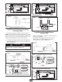
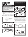
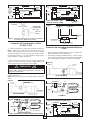
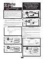
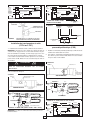
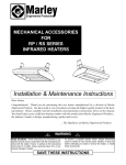
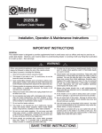
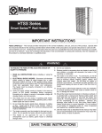
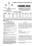
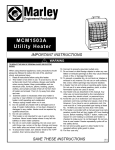
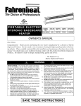
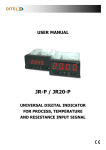
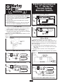
!
Electrical Accessories
for “F” Series Fan
Forced Ceiling
Mounted Heaters
WARNING
Figure 3: F-T1 (347V & 600V units)
1. To prevent permanent damage to heater or a possible fire
hazard, the control accessories described in this manual
must be wired to cycle the heating element circuit only.
The motor circuit is controlled by the fan delay and must
remain energized at all times unless heater circuit is
desconnected.
2. All control circuit wiring must be NEC Class I, rated at
least 90 degrees C.
3. Refer to the installation instruction manual provided with
the heater for additional WARNINGS and instructions.
DISCONNECT
L2
TRANSFORMER
T-STAT
FAN DELAY
MOTOR
Figure 3-A: F-T2 (347V & 600V units)
DISCONNECT
1. Install the Internal Thermostat to the heater fan panel as
shown in Figure 1 using two screws provided.
2. Wire thermostat as shown in wiring diagrams, Figure 2
and Figure 2-A for 208V, 240V, and 277V units. See Figure
3 and 3-A for 347V and 600V units.
NOTE: Push connectors securely onto the terminals to assure
proper connection.
TSTAT
LIMIT
L1
POWER
SUPPLY
ELEMENT
L1 OFF
L2
L2 CYC
GND
TRANSFORMER
MOTOR
FAN DELAY
Installation of Control Relay
(FR2 or FR12)
Figure 1
FT1 OR FT2
THERMOSTAT
1. Install the Control Relay as shown in Figure 4.
NOTE: Be sure that the tab on the control relay plate is
securely engaged in the hole in the mounting flange of the
heater fan panel securing opposite corner of mounting flange
with screw supplied.
2. To wire the relay, refer to wiring diagram in Figure 5 for
208V, 240V, and 277V units. See Figure 5A for 347V and
600V units.
3. For night setback operation, refer to wiring diagram in
Figure 6.
NOTE: The control relay must be energized for day operation.
HEATER FAN
PANEL
#6 - 32
SCREWS
Figure 2: F-T1 (208V, 240V & 277V units)
L1
ELEMENT
GND
Installation of Internal Thermostat
F-T1 or F-T2
LIMIT
DISCONNECT
POWER
SUPPLY
LIMIT
L1
POWER
SUPPLY
Figure 4
MOTOR
L2
or
N
FAN DELAY
ELEMENTS
GND
T-STAT
RED JUMPER
TOP VIEW
Figure 2-A: F-T2 (208V, 240V & 277V units)
L1
DISCONNECT
POWER
SUPPLY
T-STAT
LIMIT
L1 OFF
L2
or
N
L1
L2 CYC
POWER
SUPPLY
ELEMENTS
MOTOR
MOTOR
L2
or
N
GND
FAN DELAY
LIMIT
DISCONNECT
FAN DELAY
GND
ELEMENTS
T
RED JUMPER
CONTROL RELAY
FR2-24V
FR12-120V
RED JUMPER
WIRING FROM REMOTE THERMOSTAT
CONTROL POWER SUPPLY
Figure 5: FR2 / FR12 (208V, 240V & 277V units)
1
DISCONNECT
DISCONNECT
LIMIT
ELEMENT
ELEMENT
LIMIT
L1
L1
POWER
SUPPLY
POWER
SUPPLY
L2
L2
GND
WIRING FROM
REMOTE
THERMOSTAT
CONTROL POWER
SUPPLY
GND
TRANSFORMER
TRANSFORMER
CONTROL RELAY
FR2 - 24V
FR12 - 120V
MOTOR
CONTROL
RELAY
FAN DELAY
MOTOR
FAN DELAY
Figure 5-A: FR2 / FR12 (347V & 600V units)
Figure 8-A: F-TR4 / F-TR7
(347V & 600V units)
TO REMOTE
24V THERMOSTAT
Figure 9
FROM
TRANSFORMER
TO CONTROL
RELAY
TO REMOTE
THERMOSTAT
Figure 6
NIGHT SET BACK
THERMOSTAT
TIME
CLOCK
Installation of Transformer and Relay
(F-TR4 or F-TR7)
Installation of Pneumatic/Electric
Switch (F-PE)
1. Install the Transformer and Relay as shown in Figure 7.
NOTE: Be sure that the tab on the relay plate is securely
engaged in the hole in the mounting flange of the heater fan
panel securing opposite corner of mounting flange with screw
supplied. Mount transformer using 2 screws supplied.
1. Install the Pneumatic/Electric Switch as shown in Figure 10
using 2 screws supplied.
2. To wire the Pneumatic/Electric Switch, refer to wiring
diagram Figure 11 for 208V, 240V,and 277V units.
See Figure 11-A for 347V and 600V units.
2. To wire the transformer and relay, refer to wiring diagram in
Figure 8 for 208V, 240V, and 277V units. See Figure 8-A for
347V and 600V units.
!
Figure 10
CAUTION
TRANSFORMER VOLTAGE MUST MATCH HEATER VOLTAGE INDICATED ON HEATER NAMEPLATE.
3. For night setback operation, refer to wiring diagram Figure 9.
TOP VIEW
Figure 7
Figure 11: F-PE (208V, 240V & 277V units)
L1
POWER
SUPPLY
L1
F-PE
SWITCH
LIMIT
MOTOR
L2
or
N
FAN DELAY
T-STAT
ELEMENTS
GND
DISCONNECT
POWER
SUPPLY
MOTOR
L2
or
N
TOP VIEW
LIMIT
DISCONNECT
RED JUMPER
1/4" PNEUMATIC
TUBE
FAN DEL AY
ELEMENTS
GND
Figure 11-A: F-PE (347V & 600V units)
TRANSFORMER
DISCONNECT
CONTROL
REL AY
LIMIT
L1
RED JUMPER
ELEMENT
POWER
SUPPLY
L2
TO REMOTE THERMOS TAT
Figure 8: F-TR4/F-TR7 (208V, 240V & 277V units)
TRANSFORMER
1/4" PNEUMATIC
TUBE
GND
NOTE: The control relay must be energized for day operation.
MOTOR
2
FAN DELAY
LIMITED WARRANTY
All products manufactured by Marley Engineered Products are warranted against defects in workmanship and materials for one year
from date of installation, except heating elements which are warranted against defects in workmanship and materials for five years
from date of installation. This warranty does not apply to damage from accident, misuse, or alteration; nor where the connected voltage is more than 5% above the nameplate voltage; nor to equipment improperly installed or wired or maintained in violation of the product’s installation instructions. All claims for warranty work must be accompanied by proof of the date of installation.
The customer shall be responsible for all costs incurred in the removal or reinstallation of products, including labor costs, and shipping
costs incurred to return products to Marley Engineered Products Service Center.Within the limitations of this warranty, inoperative units
should be returned to the nearest Marley authorized service center or the Marley Engineered Products Service Center, and we will
repair or replace, at our option, at no charge to you with return freight paid by Marley. It is agreed that such repair or replacement is
the exclusive remedy available from Marley Engineered Products.
THE ABOVE WARRANTIES ARE IN LIEU OF ALL OTHER WARRANTIES EXPRESSED OR IMPLIED. AND ALL IMPLIED WARRANTIES OF MERCHANTABILITY AND FITNESS FOR A PARTICULAR PURPOSE WHICH EXCEED THE AFORESAID
EXPRESSED WARRANTIES ARE HEREBY DISCLAIMED AND EXCLUDED FROM THIS AGREEMENT. MARLEY ENGINEERED
PRODUCTS SHALL NOT BE LIABLE FOR CONSEQUENTIAL DAMAGES ARISING WITH RESPECT TO THE PRODUCT,
WHETHER BASED UPON NEGLIGENCE, TORT, STRICT LIABILITY, OR CONTRACT.
Some states do not allow the exclusion or limitation of incidental or consequential damages, so the above exclusion or limitation may
not apply to you. This warranty gives you specific legal rights, and you may also have other rights which vary from state to state.
For the address of your nearest authorized service center, contact Marley Engineered Products in Bennettsville, SC, at 1-800-6424328. Merchandise returned to the factory must be accompanied by a return authorization and service identification tag, both available
from Marley Engineered Products. When requesting return authorization, include all catalog numbers shown on the products.
HOW TO ORDER REPAIR PARTS
In order to obtain any needed repair or replacement
parts, warranty service or technical information, please
contact Marley Engineered Products Service Center tollfree by calling 1-800-642-HEAT.
When ordering repair parts, always give the information listed as follows:
1. The Part Number
2. The Model Number
3. The Part Description
4. Date of Manufacture
5200-2156-004
470 Beauty Spot Rd. East
Bennettsville, SC 29512 USA
ECR 36526
7/05
3
!
Accesorios Eléctricos para
los Calefactores Serie “F”,
Montados en Cielo Raso,
Forzados por Ventilador
ADVERTENCIA
Figura 3: F-T1 (unidades de 347V y 600V)
1. Para evitar daño permanente al calefactor o un posible riesgo de
incendio, los accesorios de control descritos en este manual deben
cablearse para encender y apagar únicamente el circuito de
elementos calefactores. El circuito del motor es controlado por el
retardo del ventilador y debe permanecer energizado a todo
momento a menos que el circuito del calefactor esté desconectado.
2. Todos los cables del circuito de control deben ser Clase I NEC,
con capacidad nominal para 90ºC mínimo.
3. Consulte el manual de instrucciones de instalación suministrado
con el calefactor para obtener ADVERTENCIAS e instrucciones adicionales.
DESCONECTADOR
DISCONNECT
FUENTE
DEPOWER
SUPPLY
ENERGÍA
L2
TRANSFORMADOR
TRANSFORMER
MOSTATO
VENTILADOR
DESCONECTADOR
DISCONNECTTERMOSTATO
TSTAT
FUENTE
L1
DE
POWER
SUPPLY
ENERGÍA
LÍMITE
LIMIT
ELEMENTO
ELEMENT
L1 OFF
L2
L2 CYC
TIERRA
TRANSFORMADOR
TRANSFORMER
MOTOR
MOTOR
RETARDO
DEL
FAN
DELAY
VENTILADOR
Instalación del Relé de Control
(FR2 ó FR12)
1. Instale el Relé de Control según se muestra en la Figura 4.
NOTA: Verifique que la pestaña en la placa del relé de control está
enganchada de manera segura dentro del orificio en el reborde de
montaje del panel del ventilador del calefactor, asegurando la
esquina opuesta del reborde de montaje con el tornillo suministrado.
2. Para cablear el relé, consulte el diagrama de cableado en la
Figura 5 para las unidades de 208V, 240V y 277V. Véase la
Figura 5A para las unidades de 347V y 600V.
3. Para la operación programable nocturna, consulte el diagrama de
cableado en la Figura 6.
NOTE: El relé de control debe estar energizado durante la operación
diurna.
PANEL DEL VENTILADOR
DEL CALEFACTOR
TORNILLOS #6 – 32
Figura 2: F-T1 (208V, 240V & 277V units)
LÍMITE
LIMIT
DESCONECTADOR
DISCONNECT
Figura 4
MOTOR
MOTOR
L2
or
N
RETARDO
DEL
FAN
DELAY
MOTOR
MOTOR
Figura 3-A: F-T2 (unidades de 347V y 600V)
TERMOSTATO
FT1 ó FT2
POWER
FUENTE DE
ENERGÍA
SUPPLY
ELEMENTO
ELEMENT
TERT-STAT
1. Instale el Termostato Interno en el panel del ventilador del calefactor según se muestra en la Figura 1, utilizando dos tornillos
suministrados.
2. Cablee el termostato según se muestra en los diagramas de
cableado, Figura 2 y Figura 2-A para las unidades de 208V, 240V
y 277V. Véase la Figura 3 y 3-A para las unidades de 347V y 600V.
NOTA: Presione firmemente los conectores sobre los terminales para
garantizar una conexión apropiada.
L1
LIMIT
TIERRA
Instalación del Termostato Interno
F-T1 ó F-T2
Figura 1
LÍMITE
L1
RETARDO DE TIEMPO
DEL RELÉ DE CONTROL FR2 ó FR12
PANEL DEL
VENTILADOR
RETARDO
DEL
FAN
DELAY
ELEMENTS
ELEMENTOS
VENTILADOR
TIERRA
GND
TERMOSTATO
T-STAT
PUENTE
ROJO
RED
JUMPER
VISTA SUPERIOR
Figura 2-A: F-T2 (unidades de 208V, 240V y 277V)
COMPARTIMIENTO DEL INTERRUPTOR DE
DESCONEXIÓN
LÍMITE
DESCONECTADOR
DISCONNECTTERMOSTATO LIMIT
L1
T-STAT
L2
or
N
LÍMITE
DESCONECTADOR
DISCONNECT
L1 OFF
FUENTE DE
ENERGÍA
LIMIT
L1
L2 CYC
FUENTE
POWER
DE
SUPPLY
ENERGÍA
ELEMENTOS
ELEMENTS
MOTOR
MOTOR
MOTOR
MOTOR
L2
or
N
RETARDO
DEL
FAN DELAY
VENTILADOR
RETARDO
DEL
FAN DELAY
VENTILADOR
TIERRA
GND
ELEMENTOS
ELEMENTS
T
PUENTE
ROJO
RED
JUMPER
RELÉ
DE CONTROL
CONTROL
RELAY
FR2-24V
FR12-120V
PUENTE
ROJO
RED
JUMPER
CABLEADO
PROCEDENTE
DE
LA FUENTE
WIRING
FROM
REMOTE
THERMOSTAT
DE ENERGÍA POWER
DE CONTROL
DEL
CONTROL
SUPPLY
TERMOSTATO REMOTO
Figura 5: FR2 / FR12 (unidades de 208V, 240V y 277V)
1
DESCONECTADOR
DISCONNECT
DESCONECTADOR
DISCONNECT
ELEMENTO
LÍMITE
LIMIT
ELEMENT
FUENTE DE
POWER
ENERGÍA
L1
POWER
FUENTE
DE
SUPPLY
ENERGÍA
ELEMENTO
ELEMENT
LÍMITE
LIMIT
L1
SUPPLY
L2
L2
CABLEADO
PROCEDENTE
DE LA FUENTE
WIRING
FROM
DE ENERGÍA DE
REMOTE
CONTROL DEL
THERMOSTAT
TERMOSTATO
CONTROL
POWER
REMOTO
SUPPLY
TIERRA
TRANSFORMADOR
TRANSFORMADOR
TRANSFORMER
RELÉ DE RELAY
CONTROL
CONTROL
FR2 - 24V
FR12 - 120V
TRANSFORMER
TIERRA
RELÉ DE
CONTROL
RELAY
CONTROL
RETARDO
FAN DELAYDEL
VENTILADOR
MOTOR
MOTOR
MOTOR
MOTOR
RETARDO
FAN DELAYDEL
VENTILADOR
Figura 5-A: FR2 / FR12 (unidades de 347V y 600V)
Figura 8-A: F-TR4 / F-TR7
(unidades de 347V y 600V)
RELÉ DE
CONTROL
HACIA EL
TOTERMOSTATO
REMOTE
24V THERMOSTAT
REMOTO
DE 24V
Figura 9
ROJO
ROJO
TERMOSTATO
PROGRAMABLE
NOCTURNO
HACIA EL RELÉ DE CONTO CONTROL
TROL
RELAY
PROCEDENTE
DEL TRANSFROM
FORMADOR
TRANSFORMER
RELOJ DE
TIEMPO
HACIA EL TO
TERMOSTATO
REMOTE
REMOTO
THERMOSTAT
Figura 6 CABLEADO PROCEDENTE DE LA FUENTE DE ENERGÍA
DE CONTROL DEL TERMOSTATO REMOTO
TERMOSTATO PROGRAMNIGHT SET BACK
ABLE NOCTURNO
THERMOSTAT
RELOJ DE
TIME
TIEMPO
CLOCK
Instalación del Transformador y el Relé
(F-TR4 ó F-TR7)
Instalación del Interruptor Neumático/Eléctrico
(F-PE)
1. Instale el Transformador y el Relé según se muestra en la Figura 7.
NOTE: Verifique que la pestaña en la placa del relé está enganchada de manera segura dentro del orificio en el reborde de montaje
del panel del ventilador del calefactor, asegurando la esquina opuesta del reborde de montaje con el tornillo suministrado. Monte el transformador utilizando 2 tornillos suministrados.
1. Instale el Interruptor Neumático/Eléctrico según se muestra en la
Figura 10 utilizando 2 tornillos suministrados.
2. Para cablear el Interruptor Neumático/Eléctrico, consulte el diagrama de cableado en la Figura 11 para las unidades de 208V, 240V y
277V. Véase la Figura 11-A para las unidades de 347V y 600V.
2. Para cablear el transformador y el relé, consulte el diagrama de
cableado en la Figura 8 para las unidades de 208V, 240V y 277V.
Véase la Figura 8-A para las unidades de 347V y 600V.
!
Figura 10
PANEL DEL VENTILADOR
INTERRUPTOR
NEUM/ELÉC
PRECAUCIÓN
EL VOLTAJE DEL TRANSFORMADOR DEBE COINCIDIR CON EL
VOLTAJE DEL CALEFACTOR INDICADO EN LA PLACA DE
DATOS DEL CALEFACTOR.
COMPARTIMIENTO
DEL INTERRUPTOR
DE DESCONEXIÓN
3. Para la operación programable nocturna, consulte el diagrama de
cableado en la Figura 9.
NOTE: El relé de control debe estar energizado durante la operación
diurna.
VISTA SUPERIOR
Figura 11: F-PE (unidades de 208V, 240V y 277V)
Figura 7
PANEL DEL
VENTILADOR
L1
RETARDO DE TIEMPO DEL RELÉ
DE CONTROL FR2 ó FR12
MOTOR
MOTOR
SUPPLY
TIERRA
L2
or
N
RETARDO
FAN
DELAY
VENTILADOR
TERMOST
T-STAT
ELEMENTOS
ELEMENTS
GND
COMPARTIMIENTO
DEL INTERRUPTOR
DE DESCONEXIÓN
VISTA SUPERIOR
LÍMITE
LIMIT
DESCONECTADOR
DISCONNECT
FUENTE DE
POWER
ENERGÍA
INTERRUPTOR
F-PE
NEUM/ELÉC
PUENTE
ROJO
RED
JUMPER
SWITCH
COMPARTIMIENTO DEL INTERRUPTOR DE DESCONEXIÓN
TUBO NEUMÁTICO DE 1/4"
L1
FUENTE DE
POWER
ENERGÍA
1/4" PNEUMATIC
TUBE
LÍMITE
LIMIT
DESCONECTADOR
DISCONNECT
Figura 11-A: F-PE (347V & 600V units)
MOTOR
MOTOR
SUPPLY
L2
or
N
RETARDO
FAN
DEL AY
VENTILADOR
DESCONECTADOR
DISCONNECT
ELEMENTOS
ELEMENTS
GND
LÍMITE
LIMIT
L1
ELEMENTO
ELEMENT
FUENTE DE
POWER
ENERGÍA
TIERRA
SUPPLY
L2
TRANSFORMADOR
TRANSFORMER
RELÉ DE
CONTROL
CONTROL
REL AY
TRANSFORMADOR
TRANSFORMER
TUBO
NEUMÁTICO
1/4"
PNEUMATIC
DE 1/4"
TUBE
PUENTE
ROJO
RED
JUMPER
TIERRA
EL TERMOSTATO
REMOTO
TOHACIA
REMOTE
THERMOS
TAT
MOTOR
MOTOR
Figura 8: F-TR4/F-TR7 (unidades de 208V, 240V y 277V)
2
FAN RETARDO
DELAY
VENTILADOR
GARANTÍA LIMITADA
Todos los productos fabricados por Marley Engineered Products están garantizados contra defectos en manufactura y materiales durante un
(1) año a partir de la fecha instalación, excepto los elementos con cubierta metálica los cuales están garantizados contra defectos en manufactura y materiales durante cinco años, y el tubo de cuarzo / lámparas de cuarzo durante dos años a partir de la fecha de instalación . Esta
garantía no aplica a daño por accidente, uso incorrecto, o alteración; ni donde el voltaje conectado sea superior en 5% al voltaje indicado en
la placa de datos; ni se aplica a equipo instalado o cableado o mantenido de manera inapropiada en violación de las instrucciones de instalación de los productos. Todas las reclamaciones de trabajos de garantía deben incluir un documento que compruebe la fecha de instalación.
El cliente será responsable de todos los costos incurridos en la remoción o reinstalación de productos, incluyendo los costos de mano de obra, y los costos de envío incurridos para devolver los productos a un Centro de Servicio de Marley Engineered Products, y nosotros repararemos o reemplazaremos,
según nuestra elección, sin costo para usted con el costo de envío de regreso pagado por Marley. Se acuerda que dicha reparación o reemplazo es el
remedio exclusivo disponible de parte de Marley Engineered Products.
LAS ANTERIORES GARANTÍAS REEMPLAZAN CUALQUIER OTRA GARANTÍA EXPRESA O IMPLÍCITA, Y TODAS LAS GARANTÍAS IMPLÍCITAS DE
MERCADEABILIDAD Y ADECUADIBILIDAD PARA UN PROPÓSITO EN PARTICULAR QUE EXCEDEN LAS GARANTÍAS EXPRESAS MENCIONADAS
SON DENEGADAS MEDIANTE ESTE DOCUMENTO Y EXCLUIDAS DE ESTE ACUERDO. MARLEY ENGINEERED PRODUCTS NO SERÁ RESPONSABLE POR DAÑOS CONSECUENCIALES QUE SURJAN CON RESPECTO AL PRODUCTO, ESTÉN O NO BASADOS EN NEGLIGENCIA,
INFRACCIÓN, RESPONSABILIDAD ESTRICTA, O CONTRATO.
Algunos estados no permiten la exclusión en la limitación de los daños incidentales o consecuenciales, de manera que la anterior exclusión o limitación
podría no aplicarse a usted. Esta garantía le proporciona a usted derechos legales específicos, y también podría tener otros derechos que varían de estado a estado.
Para obtener la dirección de su centro de servicio autorizado más cercano, comuníquese con Marley Engineered Products, Bennettsville, SC 29512 USA.
Tel. 1-800-642-4328. La mercancía devuelta a la fábrica debe incluir una autorización de devolución y la etiqueta de identificación de servicio, las cuales
pueden conseguirse en la anterior dirección. Al solicitar la autorización de devolución, incluya todos los números de catálogo mostrados en los productos.
CÓMO PEDIR PIEZAS PARA
REPARACIÓN
Con el fin de obtener cualquier pieza de repuesto o
reparación, servicio de garantía o información técnica, por favor
comuníquese con el Centro de Servicio de Marley Engineered
Products gratuitamente llamando al teléfono 1-800-642-HEAT.
Al pedir piezas para reparación, siempre suministre la siguiente información:
1. El Número de Pieza
2. El Número de Modelo
3. La Descripción de la Pieza
4. La Fecha de Fabricación
5200-2156-004
470 Beauty Spot Rd. East
Bennettsville, SC 29512 USA
ECR 36526
7/05
3
Accessoires électriques
pour chauffages Série “F”
avec ventilation forcée
montés au plafond
! AVERTISSEMENT
Schéma 3 : F-T1 (unités en 347 – 600 V)
1. Pour éviter des dommages permanents au chauffage et un
risque potentiel d’incendie, les accessoires de commande décrits
dans ce manuel doivent être câblés pour activer/désactiver le circuit
de l’élément de chauffage uniquement. Le circuit de moteur est contrôlé par la temporisation de ventilateur et doit rester activé en permanence sauf si le circuit de chauffage est débranché.
2. Tout le câblage du circuit de commande doit être en Classe 1
NEC, et spécifié pour supporter au moins 90 °C.
3. Reportez-vous au manuel des instructions d’installation fourni
avec le chauffage pour avoir des instructions et AVERTISSEMENTS
supplémentaires.
DÉCONNEXION
DISCONNECT
ALIMENPOWER
TATION
SUPPLY
SECTEUR
MOSTAT
TEMPOR.
FAN
DELAY
MOTEUR
MOTOR
VENTIL.
Schéma 3-A : F-T2 (unités en 347 – 600 V)
DÉCONNEXION
DISCONNECTTHERMOSTAT
TSTAT
ALIMENL1
TATION
POWER
SUPPLY
SECTEUR
LIMITE
LIMIT
ELEMENT
ELEMENT
L1 OFF
L2
L2 CYC
TERRE
TRANSFORMATEUR
TRANSFORMER
MOTEUR
MOTOR
TEMPOR.
FAN
DELAY
VENTIL.
Installation du relais de commande
(FR2 ou FR12)
THERMOSTAT
FT1 OU FT2
1. Installez le relais de commande comme montré au Schéma 4.
REMARQUE : Assurez-vous que le taquet sur la plaque du relais de
contrôle est bien engagé dans le trou de la bride de fixation du panneau de ventilateur du chauffage, en fixant l’angle opposé avec une
vis fournie.
2. Pour câbler le relais, reportez-vous au Schéma de câblage 5 pour
les unités en 208, 240 et 277 V, et au Schéma 5A pour celles en
347 et 600 V.
3. Pour une programmation en fonctionnement nocturne, reportezvous au Schéma de câblage 6.
REMARQUE : Le relais de commande doit être activé pour le fonctionnement diurne.
VIS #6 - 32
Schéma 2 : F-T1 (unités en 208 – 240 – 277 V)
DÉCONNEXION
DISCONNECT
L2
L2
ou
or
NN
L2
TRANSFORMATEUR
TRANSFORMER
PANNEAU DE VENTILATEUR
POWER
ALIMENTATION
SECTEUR
SUPPLY
ELEMENT
ELEMENT
THERT-STAT
1. Installez le thermostat interne sur le panneau du ventilateur du
chauffage comme montré au Schéma 1, en utilisant deux vis
fournies.
2. Câblez le thermostat comme illustré sur les Schémas de câblage
2 et 2-A pour les unités en 208 V, 240 V, et 277 V. Reportez-vous
aux Schémas 3 et 3-A pour les unités en 347 V et 600 V.
REMARQUE : Presione firmemente los conectores sobre los terminales para garantizar una conexión apropiada.
L1
LIMIT
TERRE
Installation du thermostat interne
F-T1 ou F-T2
Schéma 1
LIMITE
L1
LIMITE
LIMIT
Schéma 4
MOTEUR
MOTOR
TEMPORISATION
RELAIS DE COMMANDE
FR2 OU FR12
PANNEAU DE
VENTIL.
TEMPOR.
FAN
DELAY
ELEMENTS
ÉLÉMENTS
VENTIL.
TERRE
GND
THERMOSTAT
T-STAT
CAVALIER
ROUGE
RED
JUMPER
VUE DE DESSUS
Schéma 2-A : F-T2 (unités en 208 – 240 – 277 V)
COMPARTIMENT
DE COMMUTATEUR DE
DÉCONNEXION
LIMITE
DÉCONNEXION
DISCONNECTTHERMOSTAT LIMIT
L1
ALIMENTATION
SECTEUR
L2
L2
ou
or
N
N
T-STAT
LIMITE
DÉCONNEXION
DISCONNECT
L1 OFF
LIMIT
L1
L2 CYC
ALIMENPOWER
TATION
SUPPLY
SECTEUR
ELEMENTS
ELEMENTS
MOTEUR
MOTOR
MOTEUR
MOTOR
L2
L2
ou
or
NN
TEMPOR.
FAN
DELAY
VENTIL.
TEMPOR.
FAN
DELAY
ELEMENTS
ELEMENTS
VENTIL.
TERRE
GND
T
CAVALIER
ROUGE
RED
JUMPER
RELÉ
DE CONTROL
CONTROL
RELAY
FR2-24V
FR12-120V
CAVALIER
ROUGE
RED
JUMPER
CÂBLAGEFROM
DEPUISREMOTE
LE THERMOSTAT
DISTANT
WIRING
THERMOSTAT
ALIMENTATION
ÉLECTRIQUE
DE COMCONTROL
POWER
SUPPLY
MANDE
Schéma 5 : FR2 / FR12 (unités en 208 – 240 – 277 V)
1
DÉCONNEXION
DISCONNECT
ALIMENTATION POWER
SUPPLY
SECTEUR
DÉCONNEXION
DISCONNECT
ÉLÉMENT
LIMITE
LIMIT
ELEMENT
L2
CÂBLAGE
DEPUIS LE
THERMOSTAT
WIRING
FROM
DISTANT ALIREMOTE
MENTATION
THERMOSTAT
ÉLECTRIQUE
DE
CONTROL
POWER
COMMANDE
SUPPLY
TERRE
MOTEUR
MOTOR
L2
TRANSFORMATEUR
TRANSFORMATEUR
TRANSFORMER
RELAIS DE
COMMANDE
CONTROL
RELAY
FR2 - 24V
FR12 - 120V
ÉLÉMENT
ELEMENT
LIMITE
LIMIT
L1
ALIMENTATIONPOWER
SUPPLY
SECTEUR
L1
TRANSFORMER
TERRE
RELAIS DE
CONTROL
RELAY
COMMANDE
TEMPOR.
FAN
DELAY
MOTOR
MOTEUR
VENTIL.
TEMPOR.
FAN
DELAY
VENTIL.
Schéma 5-A : FR2 / FR12 (unités en 347 et 600 V)
Schéma 8-A: F-TR4 / F-TR7
(unités en 347 et 600V)
RELÉ DE
CONTROL
VERS THERMOSTAT
TO REMOTE DIS24V
THERMOSTAT
TANT
24 V
Schéma 9
ROJO
ROJO
THERMOSTAT PROGRAM. NOCTURNE
VERS LE RELAIS DE
TO CONTROL
COMMANDE
RELAY
DEPUIS
LE TRANS
FROM
FORMATEUR
TRANSFORMER
HORLOGE
VERS THERMOSTAT
DISTO REMOTE
TANT
THERMOSTAT
CÂBLAGE DEPUIS LE THERMOSTAT DISTANT
ALIMENTATION ÉLECTRIQUE DE COMMANDE
Schéma 6
THERMOSTATPROGRAM.
NIGHT SET BACK
NOCTURNE
THERMOSTAT
HORLOGE
TIME
CLOCK
Installation de transformateur et relais
(F-TR4 ou F-TR7)
Installation du commutateur
pneumatique/électrique (F-PE)
1. Installez le transformateur et relais comme montré au Schéma 7.
REMARQUE : Assurez-vous que le taquet sur la plaque du relais de
contrôle est bien engagé dans le trou de la bride de fixation du panneau de ventilateur du chauffage, en fixant l’angle opposé avec une
vis fournie. Montez le transformateur en utilisant deux vis fournies.
2. Pour câbler le transformateur et relais, reportez-vous au Schéma 8
pour les unités en 208, 240 et 277 V, et au Schéma 8-A pour celles en
347 et 600 V.
!
1. Installez le commutateur pneumatique/électrique comme montré au
Schéma 10 en utilisant deux vis fournies.
2. Pour câbler le commutateur pneumatique/électrique reportez-vous
au Schéma 11 pour les unités en 208, 240 et 277 V, et au Schéma
11-A pour celles en 347 et 600 V.
Schéma 10
ATTENTION
PANNEAU DE
VENTIL.
LA TENSION DU TRANSFORMATEUR DOIT CORRESPONDRE À
CELLE DU CHAUFFAGE INDIQUÉE SUR SA PLAQUE
SIGNALÉTIQUE.
COMMUTATEUR P E
3. Pour une programmation en fonctionnement nocturne, reportezvous au Schéma de câblage 9.
COMPARTIMENT DE
COMMUTATEUR DE
DÉCONNEXION
Schéma 7
VUE DE DESSUS
PANNEAU DE
VENTIL
TEMPORISATION RELAIS DE COMMANDE FR2 OU FR12
Schéma 11 : F-PE (unités en 208 – 240 – 277 V)
L1
COMPARTIMENT DE
COMMUTATEUR DE
DÉCONNEXION
VUE DE DESSUS
TRANSFORMATEUR
FTR4 OU FTR7
TERRE
LIMITE
LIMIT
DÉCONNEXION
DISCONNECT
ALIMENTAPOWER
TION
SECTEUR
SUPPLY
MOTEUR
MOTOR
L2
or
N
FANTEMPOR.
DELAY
VENTIL.
TERMOST
T-STAT
ELEMENTS
ELEMENTS
GND
L1
LIMITE
LIMIT
DÉCONNEXION
DISCONNECT
ALIMENTAPOWER
TION
SUPPLY
SECTEUR
COMMUTATEUR
F-PE
F-PE
CAVALIER
ROUGE
RED
JUMPER
SWITCH
MOTEUR
MOTOR
TUBE PNEUMATIQUE 1/4"
L2
or
N
TEMPOR.
FAN
DEL AY
1/4" PNEUMATIC
TUBE
ELEMENTS
ELEMENTS
VENTIL.
GND
TERRE
Schéma 11-A : F-PE (unités en 347 et 600 V)
TRANSFORMATEUR
TRANSFORMER
RELAIS DE
CONTROL
COMMANDE
REL AY
TO
DÉCONNEXION
DISCONNECT
CAVALIER
ROUGE
RED
JUMPER
LIMITE
LIMIT
L1
ALIMENTAPOWER
TION
SUPPLY
SECTEUR
VERS
THERMOSTAT
DISTANTTAT
REMOTE
THERMOS
Schéma 8 : F-TR4/F-TR7 (unités en 208 – 240 – 277 V)
L2
TRANSFORMATEUR
TRANSFORMER
TUBE
PNEUMA1/4"
PNEUMATIC
TIQUE 1/4"
TUBE
REMARQUE : Le relais de commande doit être activé pour le fonctionnement diurne.
TERRE
MOTEUR
MOTOR
2
ELEMENT
ELEMENT
TEMPOR.
VENTIL.
FAN
DELAY
GARANTIE LIMITÉE
Tous les produits fabriqués par Marley Engineering Products sont garantis contre les défauts de main d’œuvre et de matériaux pendant un an à partir de
la date d’installation, sauf les éléments à gaine métallique qui sont garantis contre les défauts de main d’œuvre et de matériaux pendant cinq ans, et les
lampes/tubes à quartz qui sont garantis pendant deux ans, à partir de la date d’installation. Cette garantie ne s’applique pas aux dommages résultant d’accident, d’utilisation impropre ou d’altération, ni si la tension secteur appliquée est plus de 5% au-dessus de la valeur donnée sur la plaque signalétique, ni
si l’équipement a été mal installé ou mal câblé, ou mal entretenu, sans respecter les instructions fournies avec le produit; Toutes les réclamations au titre
de la garantie devront être accompagnées d’une preuve de la date d’installation.
Le client sera responsable de tous les frais causés par l’enlèvement ou la réinstallation des produits, y compris les frais de main d’oeuvre et les frais d’expédition pour renvoyer les produits au centre d’entretien Marley Engineered Products. Dans le cadre des limites de cette garantie, les appareils défaillants
doivent être renvoyés au centre de service après-vente agréé Marley le plus proche ou au centre Marley Engineered Products et nous les réparerons ou
remplacerons, à notre choix, gratuitement pour vous avec les frais de retour payés par Marley. Il est entendu qu’une telle réparation ou un tel remplacement sont les seuls recours pouvant être obtenus de Marley Engineered Products.
LES GARANTIES CI-DESSUS REMPLACENT TOUTES LES AUTRES GARANTIES EXPLICITES OU IMPLICITES ET TOUTES LES GARANTIES
IMPLICITES DE COMMERCIABILITÉ ET D’ADAPTATION À UN USAGE PARTICULIER QUI DÉPASSENT LES GARANTIES EXPLICITES DÉCRITES
CI-DESSUS SONT RÉFUTÉES PAR LA PRÉSENTE ET EXCLUES DE CET ACCORD. Marley Engineered Products NE SERA PAS RESPONSABLE DES
DOMMAGES CIRCONSTANCIELS CAUSÉS PAR LE PRODUIT, QUE CE SOIT PAR NÉGLIGENCE, DÉLIT, RESPONSABILITÉ STRICTE, OU CONTRAT.
Certaines provinces n’autorisent pas l’exclusion ou la limitation des dommages circonstanciels ou fortuits, de sorte que l’exclusion ou la limitation ci-dessus
peuvent donc ne pas vous concerner. Cette garantie vous donne des droits légaux spécifiques et vous pouvez aussi avoir d’autres droits qui varient d’une
province à l’autre.
Pour l’adresse de notre centre d’entretien autorisé le plus proche, contacter Marley Engineered Products, Bennettsville, SC 29512 USA en téléphonant au
1-800-642-4328. La marchandise renvoyée en usine doit être accompagnée d’étiquettes d’identification d’autorisation de renvoi et de service, disponibles
chez Marley Engineered Products. Lors de la demande d’autorisation de renvoi, inclure tous les numéros de catalogue apparaissant sur les produits.
COMMENT COMMANDER DES
PIÈCES POUR RÉPARATION
De façon à obtenir toute pièce pour réparation ou remplacement, des services sous garantie ou des informations techniques, veuillez contacter le centre de service de Marley
Engineered Products au numéro d’appel sans frais :
1-800-642-HEAT.
Quand vous commandez des pièces détachées fournissez
toujours les informations suivantes :
1. Numéro référence de pièce
2. Numéro de modèle
3. Description de la pièce
4. Date de fabrication
5200-2156-004
470 Beauty Spot Rd. East
Bennettsville, SC 29512 USA
ECR 36526
7/05
3