1
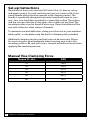
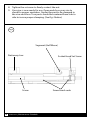
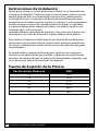
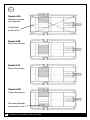
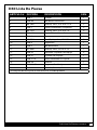
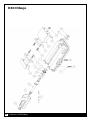
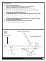
D40 AngLock® Vise
Base Assembly
Operating Instructions Manual
Manual de instrucciones de operación
ENGLISH
ESPAÑOL
Table of Contents
Introduction..................................................................................................................3
Setup Instructions.......................................................................................................4
Operating Instructions..........................................................................................5-6
D40 Parts List................................................................................................................7
D40 Mechanical Drawing.....................................................................................8-9
Maintenance Schedule.....................................................................................10-12
Troubleshooting Tips.............................................................................................. 13
Vise Data
Use this to fill out information about your vise for quick reference.
Purchase Date:
Purchase Order:
Purchased From:
Delivery Date:
Serial No.:
________ -________-________
________________________
________________________
________________________
________________________
Note:
Make sure to register your warranty online at kurtworkholding.com
2
ENGLISH | Table of Contents
Introduction
Thank you for purchasing a Kurt vise. You have just purchased one of
the best machine vises in the industry. The outstanding accuracy of this
product is second to none. Backed by a lifetime limited warranty, this
product will last many years when used and maintained properly.
The original Kurt AngLock Vises are designed for precision clamping
on a machine table. They can be used for, but not limited to operations
like precision boring, drilling, tapping, and finishing.
Each pound of force in this direction.
Induces 1/2 pound of force in this direction.
Spherical segment
(hardened) produces
“all directional”
alignment.
Introduction | ENLGISH
3
Set-up Instructions
Now that you have your new Kurt HD-Series Vise, it’s time to set-up
and begin using it. You will see that your new vise comes with a Kurt
swivel handle and instruction manual in the shipping carton. The
handle is specifically designed to provide maximum torque to your
vise. Your vise should be mounted to a clean, flat surface. The surface
and the vise must be free of any chips, dirt or debris of any kind. The
mounting surface can be honed if necessary. Clean the bottom of the
vise with solvent or other cleaner if needed.
To minimize vise bed deflection, clamp your Kurt vise to your machine
table, pallet, or sub-plate using the built-in clamping slots provided.
Additional clamping can be used, but may not be necessary. Please
be sure to exercise good judgment when securing your vise to the
mounting surface. Be sure your vise is secured and will not move when
applying the machine pressure.
Manual Vise Clamping Force
4
Torque Ft.-Lbs.
D40
10
20
30
40
50
60
1653
2923
4103
5241
6513
7807
ENGLISH | Set-Up Instructions
Operating Instructions
For proper vise operation insert the handle on to the hex end of the
vise. Rotate clockwise to clamp and counterclockwise to unclamp your
vise. This handle, combined with the correct amount of torque will
provide you with all the clamping force you will need to machine your
parts. DO NOT use any other type of pressure to open or close your
vise.
The uses of handle extensions, air impact wrenches, breaker
bars or hammer strikes are not recommended and will void the
warranty if used. This will also cause damage to the thrust bearing
and screw threads. If you need more clamping force you may require a
larger vise.
To properly clamp a part in your Kurt vise you should place the part in
the center of the jaws resting on the ways of the vise. Clamping only
on one side or above the movable and stationary jaws can result in jaw
lift or loss of accuracy. (See Fig. 1 on next page)
If one-sided clamping is necessary you MUST use a dummy part on
the other side. When using parallels or step jaws you must select a size
that keeps the bottom of the clamped part at or below the top of the
movable and stationary jaws. Always use jaw plates for clamping. If jaw
plates are not used damage to the mounting surface of the movable
and stationary jaw will occur. This will result in reduced clamping
accuracy and repeatability.
Operating Instructions | ENLGISH
5
Fig.1
Sketch #2A
Incorrect part
clamping.
Vise width
centerline
Sketch #2B
Correct part
clamping.
Sketch #2C
Correct part
clamping.
Sketch #2D
Correct part
clamping.
Nonmachined
spacer
6
ENGLISH | Operating Instructions
D40 Parts List
ITEM#
PART#
DESCRIPTION
QTY.
1
D40-1
BODY
1
2
D40-6A
STATIONARY JAW
1
3
00-1362
SCREW,SHCS,3/8-16 X 2-1/4
2
4
D40-7
JAW PLATE, PURCHASED.
2
5
00-1353
SCREW,SHCS,3/8-16 X 7/8
4
6
D40-12A
CAP, PLASTIC YELLOW
1
7
D40-3
NUT
1
9
07-0230
SCREW,DRIVE,#2 X .25
2
10
D40-9
SEGMENT,
1
11
D40-2
MOVABLE JAW
1
12
01-3908
SCREW,SHSS,3/8-16 X 7/8
1
13
D40-42
WASHER, THRUST BEARING,
3
14
D40-41
THRUST BEARING
1
15
D40-217A
SPIRAL RETAINING RING
1
16
D40-5A
SCREW
1
17
D40I-10-SA
HANDLE ASS'Y
1
18
D40-68
O-RING, BUNA N, #024
1
D40 Parts List | ENLGISH
7
D40 Drawing
8
ENGLISH | D40 Mechanical Drawing
Maintenance Schedule
It is very important to perform regularly maintenance on your Kurt vise
to assure proper operation. Improper maintenance will result in poor
vise performance and may void your warranty.
Daily / Weekly
1.
2.
3.
4.
Remove chips from surface of vise.
Visually inspect for chips, seals for damage and cleanliness.
Visually inspect for chip entrapments and remove when necessary.
Air-dry and apply rust inhibiting oil to the machined surface of the
vise.
Monthly
1. Open the vise to the maximum opening.
2. In the back of the movable jaw (handle end, center hole) loosen
the socket head set screw (approx. 6 turns) With the hex key (Allen
wrench) in the set-screw socket lift up and forward to pivot the Jaw
off of the vise bed.
3. Slide the Jaw slightly toward the stationary jaw and lift up to
remove the jaw from the “hook” of the nut. Note: A spherical
segment (shaped as ½ of a steel ball) is inside the cavity of the
movable jaw and may fall out as the jaw is removed. Take care not
to lose or misplace the spherical segment.
4. Turn the movable jaw over and clean the inside cavity. Also clean
the spherical segment.
5. Remove chips, clean and apply a light coat of machine oil to the
machined surface of the following items:
a. Nut & Screw assembly (clean exposed threads on the screw
b. Bed of vise (top of “rails”)
c. Inside of the vise between the center ways.
6. To re-assemble the movable jaw, apply a “glob” of grease to the
under side of the movable jaw in the pocket. Place the spherical
segment in the mating pocket and push into the grease. The
grease will hold the segment in place when the jaw is turned over
to replace.
7. Tip the jaw so the front of the jaw (the side with the jaw plate) is on
the vise bed. Lower the jaw on to the bed so that the segment
contact the hook part of the nut and rest the jaw on to the vise
bed.
Maintenance Schedule | ENLGISH
9
8.
9.
Tighten the setscrew to firmly contact the nut.
Your vise is now ready for use. Open and close your vise to
check for proper operation. Center the part to be clamped in
the vise and close. Your parts should be centered from side to
side to insure proper clamping. (See Fig. 2 below)
Fig.2
Segment (Half Moon)
Stationary Jaw
Screw
10
ENGLISH | Maintenance Schedule
Socket Head Set Screw
Screw brush seals
3 to 6 months
1. Open vise to maximum opening.
2. Remove spiral snap ring and washer from hex end of the vise
screw.
3. Slide the movable jaw toward the stationary.
4. Remove the thrust bearing assembly consisting of (2) thrust
washers and (1) thrust bearing from the counter bore in the end of
the body.
5. Clean and inspect the counter bore, thrust washers and thrust
bearing.
6. Apply water resistant grease to the thrust washer (i.e. marine grade
grease)
7. Install thrust bearing assembly on the screw and slide movable jaw
back.
8. Install washer and spiral retaining ring.
9. Your vise is now ready to use.
Maintenance Schedule | ENLGISH
11
Troubleshooting Tips
The Kurt D-Series vise will operate mostly trouble free for many years.
If properly maintained, this product is indestructible. In some cases it
will be necessary to troubleshoot. Use the information below to help in
the process.
Problem: My vise turns hard.
Tip: As a new vise the brush seal could be stiff. Allow for break in of
vise.
Tip: As a used vise, it could be filed with chips and threads could be
jammed. Properly clean and grease vise.
Problem: My vise will not turn in either direction.
Tip: The vise is jammed with debris. Disassemble and clean as
needed.
Problem: My vise won’t hold tolerance.
Tip: You may be experiencing jaw lift from clamping too high or on
one side of the jaw. Lower the part in the vise jaw and clamp more
material.
12
ENGLISH | Troubleshooting Tips
Maintenance Log/Notes:
Maintenance Log/Notes | ENLGISH
13
Maintenance Log/Notes:
14
ENGLISH | Maintenance Log/Notes
Thank you for your purchase!
If you have any feedback or questions.
Please contact us at:
[email protected]
or
1-877-226-7823
Like, Tweet, and Subscribe to us!
All Kurt Manufacturing Company industrial workholding products and parts with the
exceptions noted below, are warranted against defects in material and workmanship
for the life of the product or part. (The life of the product is defined as that point in
time when such item no longer functions due to normal wear and tear.) Failure to
properly maintain and/or properly operate the product or part that has been worn
out, abused heated ground or otherwise altered, used for a purpose other than that
for which it was intended, or used in a manner in consistent with any instructions
regarding its use. The sole obligation of Kurt Manufacturing Company, Inc. (Kurt)
and the purchaser’s SOLE AND EXCLUSIVE REMEDY hereunder, shall be limited
to the replacement or repair of any Kurt product or part (by an authorized Kurt
technician) which are returned to Kurt Manufacturing Company’s place of business,
transportation, shipping and postal charges prepaid, and there determined by Kurt
Manufacturing Company to be covered by the warranty contained herein.
THE LIMITED WARRANTY DESCRIBED HEREIN IS MADE EXPRESSLY IN LIEU OF ANY
OTHER EXPRESSED OR IMPLIED WARRANTIES, INCLDING ANY IMPLIED WARRANTY OF
MERCHANTABLITY OR FITNESS FOR A PARTICULAR PURPOSE. KURT MANUFACTURING
COMPANY IS NOT RESPONSIBLE FOR THE IMPROPER USE OF ITS PRODUCTS.
KURT SHALL NOT BE LIABLE FOR ANY DIRECT, INDIRECT, INCIDENTAL SPECIAL OR
CONSEQUENTIAL DAMAGES, INCLUDING BUT NOT LIMITED TO, LOSS OF USE, REVENUE
OR PROFIT.
KURT ASSUMES NO LIABILITY FOR, AND MAKES NO WARRANTY REGARDING ANY
PURCHASE ITEMS WHERE THE MANUFACTURER OF SUCH ITEM EXTENDS A SEPARATE
WARRANTY.
9445 East River Road NW
Minneapolis, MN 55433
Phone: 877-226-7823
Fax: 877-226-7828
Troubleshooting Tips
kurtworkholding.com
Manual Revision: 02.20.2012
Prensa D40 AngLock®
Ensamble de Base
Manual de instrucciones de operación
ESPAÑOL
Tabla de contenido
Introducción............................................................................................................... 19
Setup Instructions.................................................................................................... 20
Operating Instructions.....................................................................................21-22
D40 List De Piezas.................................................................................................... 23
D40 Dibujo Mecánico ......................................................................................24-25
Programa de mantenimiento........................................................................26-28
Sugerencias para la resolución de problemas............................................... 29
Vise Datos
Utilice esta opción para rellenar la información sobre el tornillo de
banco para referencia rápida
Fecha de compra:
Orden de compra:
Adquirido en:
Fecha de entrega:
Serial No.:
______ -_______ -_______
______________________
______________________
______________________
______________________
Note:
Make sure to register your warranty online at kurtworkholding.com
18
ESPAÑOL | Tabla de contenido
Introducción
Muchas gracias por comprar una prensa Kurt. Usted ha comprado una
de las mejores prensas para mecanizado de la industria. La prensa
AngLock™ Serie D tiene un diseño ampliamente comprobado. La
extraordinaria exactitud de este producto es insuperable. Con el
respaldo de una garantía de por vida, este producto durará mucho
tiempo cuando se lo use y mantenga correctamente.
Las prensas Kurt Anglock™ originales están diseñadas para el sujetado
de precisión en máquinas herramientas básicas como las fresadoras
de tipo acodado (knee-type), esmeriladoras y centros de mecanizado.
Se pueden utilizar en, sin limitarse a, operaciones de barrenado,
taladrado, roscado, fresado y acabados de precisión.
El diseño patentado de Anglock™ permite a la mordaza móvil avanzar
de tal manera que cada libra de fuerza de avance induzca ½ libra de
fuerza hacia abajo a fin de minimizar el levantamiento de la mordaza
y aumente la exactitud. Este efecto combinado con los cojinetes de
agujas aumenta la presión de sujeción de la mordaza. Entre otras
características se incluyen: Cuerpo de hierro dúctil de 80,000 psi de
resistencia, carriles de prensa y placas de mordaza endurecidas, tornillo
de avance semiendurecido.
Cada libra de fuerza en esta dirección.
Induce 1/2 libra de fuerza en esta dirección.
El segmento
serniesférico
(endurecido) produce
la alineación en “todas
las direcciones”
Introducción | ESPAÑOL
19
Instrucciones de instalación
Ahora que ya tiene su nueva prensa Kurt Serie D, es el momento de
comenzar a utilizarla. Usted verá que su nueva prensa viene con una
manija giratoria Kurt y un manual de instrucciones suministrados
en la caja de envío. La manija está diseñada específicamente para
proporcionar el máximo par de torsión a su prensa. Le recomendamos
instalar la prensa sobre una superficie plana y limpia. La superficie
y la prensa deben estar exentas de virutas, suciedad o residuos de
cualquier tipo. Si es necesario,
se puede afinar la superficie de montaje. Si es necesario, limpie con
disolvente u otro tipo de limpiador la parte inferior de la prensa.
Para reducir al mínimo la deformación por flexión de la plataforma
de la prensa, fije la prensa Kurt a la mesa de la máquina, plataforma
de carga, o subplaca por medio de las ranuras de sujeción integrales
suministradas.
Se puede utilizar sujeción adicional, pero quizá no sea necesario.
Cerciórese de aplicar buen juicio al fijar su prensa a la superficie de
montaje. Cerciórese de que su prensa esté firmemente sujetada y que
no se moverá al aplicar la presión de la máquina.
Fuerza de Sujeción de la Prensa
20
Par de torsión libras-pie
D40
10
20
30
40
50
60
1653
2923
4103
5241
6513
7807
ESPAÑOL | Instrucciones de instalación
Instrucciones de operación
Para el funcionamiento apropiado de la prensa introduzca el mango
en el extremo hexagonal de la prensa. Gírelo a la derecha para apretar
y a la izquierda para aflojar la prensa. Esta manija combinada con
la cantidad apropiada de par de torsión le proporcionará la fuerza
de sujeción necesaria para mecanizar sus piezas de trabajo. NO use
ningún otro tipo de presión para abrir o cerrar su prensa.
No se recomienda el uso de extensiones de manijas, llaves
neumáticas de impacto, barras de ruptura ni golpes de martillo
ya que su uso anulará la garantía. Además, esto causará daño al
cojinete de empuje y a las roscas del tornillo. Si necesita mayor fuerza
de sujeción quizá deba actualizar la prensa y utilizar una de mayor
capacidad.
Para sujetar debidamente una pieza en su prensa Kurt le sugerimos
colocar la pieza en el centro de las mordazas y apoyarla en los
carriles de la prensa. La sujeción cargada en uno solo de los lados
o por encima de las mordazas móviles y estacionarias puede resultar
en el levantamiento de la mordaza o la pérdida de exactitud.
(Véase la Fig. 1 en la página siguiente).
Si fuera necesario sujetar por uno solo de los lados, será
NECESARIO equilibrar colocando un postizo en el otro lado.
Al utilizar mordazas paralelas o escalonadas deberá seleccionar
un tamaño que mantenga la parte inferior de la pieza sujeta en o
debajo de la parte superior de las mordazas móviles y estacionarias.
Siempre use placas de mordaza para la sujeción. Si no se utilizan
placas de mordaza ocurrirán daños a la superficie de montaje de las
mordazas móviles y estacionarias. Esto resultará en menor exactitud y
repetitividad deficiente del prensado.
Instrucciones de operación | ESPAÑOL
21
Fig.1
Sketch #2A
Parteincorrecta
de sujeción.
Central de
ancho Vise
Sketch #2B
Parte de amarre.
Sketch #2C
Parte de amarre.
Sketch #2D
Parte de amarre.
No mecanizadas
espaciador
22
ESPAÑOL | Instrucciones de operación
D40 Lista De Piezas
ARTÍCULO # DE PIEZA
DESCRIPCIÓN
CAN.
1
D40-1
Cuerpo
1
2
D40-6A
Mordaza Estacionaria
1
3
00-1362
Tornillo, SHCS, 3/8-16 X 2-1/4
2
4
D40-7
Placa De Mordaza, Comprada
2
5
00-1353
Tornillo, SHCS, 3/8-16 X 7/8
4
6
D40-12A
Tapón Plástico Amarillo
1
7
D40-3
Tuerca
1
9
07-0230
Tornillo, Impulsor, #2 X .25
2
10
D40-9
Segmento
1
11
D40-2
Mordaza Móvil
1
12
01-3908
Tornillo, SHSS, 3/8-16 X 7/8
1
13
D40-42
Arandela, Cojinete De Empuje
3
14
D40-41
Cojinete De Empuje
1
15
D40-217A
Anillo Retenedor En Espiral
1
16
D40-5A
Tornillo
1
17
D40I-10-SA
Conjunto De Manija
1
18
D40-68
Arosello, Buna N, #24
1
*El conjunto de manija no se muestra en la vista despiezada.
D40 LIsta De Piezas | ESPAÑOL
23
D40 Dibujo
24
ESPAÑOL | D40 Dibujo
Programa de mantenimiento
Para asegurar el funcionamiento correcto, es de suma importancia
realizar el mantenimiento regular en su prensa Kurt. El mantenimiento
erróneo resultará en el desempeño deficiente de la prensa y puede
anular su garantía.
Diariamente / Semanalmente
1. Retire las virutas de la superficie de la prensa.
2. Inspeccione visualmente para verificar que no haya virutas, daños
en los sellos y la limpieza en general.
3. Inspeccione visualmente para verificar que no haya depósitos de
virutas y eliminarlos cuando sea necesario.
4. Seque con aire comprimido y aplique aceite inhibidor de corrosión
a todas las superficies rectificadas de la prensa.
Mensualmente
1. Abra la prensa al máximo.
2. En la parte posterior de la mordaza móvil (extremo de la manija,
orificio central) afloje el tornillo de ajuste de cabeza hueca
hexagonal (aprox. 6 vueltas). Con la llave hexagonal (llave Allen)
en la cabeza hueca del tornillo de ajuste levántela y muévala hacia
adelante para pivotar la mordaza y sacarla de la plataforma de la
prensa.
3. Deslice levemente la mordaza hacia la mordaza estacionaria y
levántela para sacar la mordaza del “gancho” de la tuerca. Nota:
Un segmento semiesférico (con la forma de ½ bola de acero) se
encuentra en el interior de la cavidad de la mordaza móvil y se
puede caer al retirar la mordaza. Tenga cuidado de no aflojar ni
colocar indebidamente el segmento semiesférico.
4. Voltee la mordaza móvil y limpie el interior de la cavidad. Además,
limpie el segmento semiesférico.
5. Retire las virutas, limpie y aplique una capa liviana de aceite
de máquina a la superficie maquinada de los componentes
siguientes:
a.
b.
c.
Conjunto de tuerca y tornillo
(limpie las roscas expuestas en el tornillo)
Plataforma de la prensa (parte superior de los “carriles”)
En el interior de la prensa entre los carriles centrales.
Programma de mantenimiento | ESPAÑOL
25
6. Para reensamblar la mordaza móvil, aplique una “bola” de grasa a
la superficie inferior de la mordaza móvil en la cavidad. Coloque el
segmento semiesférico en la cavidad correspondiente y empújelo
hacia la grasa. La grasa retendrá en posición el segmento al voltear
la mordaza para reinstalarla.
7. Incline la mordaza de manera que el frente de la misma (el lado
con la placa de mordaza) quede sobre la plataforma de la prensa.
Baje la mordaza para apoyarla sobre la plataforma de manera que
el segmento haga contacto con la parte arqueada de la tuerca y el
resto de la mordaza se apoye sobre la plataforma de la prensa.
8. Apriete el tornillo de ajuste para que haga contacto firme con la
tuerca. Retroceda el tornillo de ajuste ¼ de vuelta (aprox.) nota: NO
deje el tornillo de ajuste apretado firmemente contra la tuerca ya
que esto puede provocar el funcionamiento erróneo. La mordaza
móvil está diseñada para moverse levemente (pivotar de lado a
lado) de manera que se obtenga el máximo contacto con la placa
de la mordaza al prensar piezas que no tengan bordes paralelos,
aserradas, o piezas fundidas.
9. Su prensa ya está lista para el uso. Abra y cierre su prensa para
verificar el funcionamiento correcto. Centre en la prensa la pieza
a sujetar y cierre la prensa. Para asegurar la sujeción correcta,
sus piezas deben estar centradas de lado a lado para asegurar la
sujeción correcta. (Véase la fig. 2 de abajo)
26
ESPAÑOL | Programma de mantenimiento
3 a 6 meses
1. Abra la prensa al máximo.
2. Retire el anillo de presión en espiral y la arandela del
extremo hexagonal del tornillo de la prensa.
3. Deslice la mordaza móvil en dirección a la estacionaria.
4. Retire el conjunto del cojinete de empuje que consiste en (2)
arandelas de empuje y (1) cojinete de empuje desde el rebajo
avellanado en el extremo del cuerpo.
5. Limpie e inspeccione el rebajo avellanado, arandelas de presión y
el cojinete de empuje.
6. Aplique grasa resistente al agua a la arandela de empuje (grasa
para uso náutico)
7. Instale el conjunto del cojinete de empuje en el tornillo y deslice
hacia atrás la mordaza móvil.
8. Instale la arandela y el anillo retenedor en espiral.
9. ¡Su prensa ya está lista para el uso!
Segmento (Media Luna)
Fig.2
Mordaza fija
Cabeza hueca Tornillo
Tornillo
Tornillo de juntas
de cepillo
Programma de mantenimiento | ESPAÑOL
27
Sugerencias para la resolución de problemas
La prensa Kurt Serie D funcionará prácticamente sin problemas
durante muchos años. Si se le brinda el mantenimiento apropiado,
este producto es indestructible. En algunos casos será necesario
resolver algunos problemas. Use la información que se indica a
continuación como ayuda en el proceso.
Problema: Mi prensa gira con dificultad.
Sugerencia: Como cualquier prensa nueva, el sello de la escobilla
puede estar rígido. Deje transcurrir un período de funcionamiento
inicial de la prensa.
Sugerencia: Como prensa con algún tiempo de uso, ésta podría estar
obstruida con virutas y las roscas podrían estar atoradas.
Limpie y engrase correctamente la prensa.
Problema: Mi prensa no gira en ninguna dirección.
Sugerencia: La prensa está atorada con residuos. Desensámblela
y límpiela según sea necesario.
Problema: Mi prensa no conserva el margen de tolerancia.
Sugerencia: Quizá se esté elevando la mordaza debido a que la pieza
sujeta está muy elevada o cargada a un lado de la mordaza. Baje la
pieza en la mordaza de la prensa y sujete más material.
28
ESPAÑOL | Sugerencias para la resolución de probelmas
Registro de Mantenimiento / Notas:
Registro de Mantenimiento / Notas | ESPAÑOL
29
Maintenance Log/Notes:
30
ESPAÑOL | Registro de Mantenimiento / Notas
¡Muchas gracias!
Si tiene algún comentario o preguntas.
comuníquese con nosotros en
[email protected]
o
877-226-7823
Al igual que, Tweet, y suscribirse a nosotros!
Todos los productos y piezas industriales para sujeción de piezas de trabajo de
Kurt Manufacturing Company con las excepciones indicadas más adelante, están
garantizados contra defectos de fabricación y materiales durante toda la vida útil del
producto de la pieza. (La vida útil del producto se define como el punto en el tiempo
en el que dicho producto ya no funciona debido al desgaste normal debido al uso).
La falta de mantenimiento apropiado y/o el uso erróneo del producto o pieza que se
haya gastado, abusado, calentado, desbastado o modificado de otra manera, utilizado
para un propósito diferente al original, o utilizado de manera incoherente con las
instrucciones respecto a su uso. La única obligación de Kurt Manufacturing Company,
Inc. (Kurt) y la ÚNICA Y EXCLUSIVA COMPENSACIÓN del comprador en virtud del
presente documento, habrá de estar limitada al reemplazo o reparación de cualquier
producto o pieza de Kurt (realizada por un técnico autorizado de Kurt) siempre que
sean devueltos al local comercial de Kurt Manufacturing Company, con los gastos
de transporte, envío y porte postal pagados previamente, y que Kurt Manufacturing
Company determine que están cubiertos por la garantía incluida en el presente
documento.
LA GARANTÍA LIMITADA QUE SE DESCRIBE EN EL PRESENTE DOCUMENTO SE
OTORGA EXPRESAMENTE EN VEZ DE CUALESQUIERA OTRAS GARANTÍAS EXPRESAS
O IMPLÍCITAS, INCLUSO CUALQUIER GARANTÍA IMPLÍCITA DE COMERCIABILIDAD O
IDONEIDAD PARA UN PROPÓSITO PARTICULAR. KURT MANUFACTURING COMPANY
NO ES RESPONSABLE DEL USO INDEBIDO DE SUS PRODUCTOS. KURT NO HABRÁ DE
SER RESPONSABLE POR DAÑOS DIRECTOS, INDIRECTOS, INCIDENTES, ESPECIALES
O CONSECUENTES, INCLUIDOS ENTRE OTROS, LA PÉRDIDA DE USO, INGRESO O
UTILIDADES.
KURT NO ASUME NINGUNA RESPONSABILIDAD POR, NI OTORGA GARANTÍA ALGUNA
PARA, NINGÚN ARTÍCULO COMPRADO EN EL CUAL EL FABRICANTE DE DICHO
ARTÍCULO EMITA UNA GARANTÍA POR SEPARADO.
9445 East River Road NW
Minneapolis, MN 55433
Phone: 877-226-7823
Fax: 877-226-7828
Troubleshooting Tips
kurtworkholding.com
Manual Revision: 01.26.2012