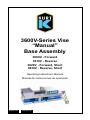
1
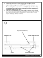
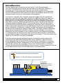
3600V-Series Vise
“Manual”
Base Assembly
3600V - Forward
3610V - Reverse
3620V - Forward, Short
3630V - Reverse, Short
Operating Instructions Manual
Manual de instrucciones de operación
ENGLISH
ESPAÑOL
Table of Contents
Introduction..................................................................................................................3
Setup Instructions.......................................................................................................4
Operating Instructions..........................................................................................5-7
3600V Parts List............................................................................................................8
3600V Mechanical Drawing.....................................................................................9
3610V Parts List......................................................................................................... 10
3610V Mechanical Drawing.................................................................................. 11
3620V Parts List......................................................................................................... 12
3620V Mechanical Drawing.................................................................................. 13
3630V Parts List......................................................................................................... 14
3630V Mechanical Drawing.................................................................................. 15
For Unit Valve............................................................................................................. 18
Maintenance Schedule.....................................................................................16-19
Troubleshooting Tips.............................................................................................. 20
CAUTION:
Is used when your action or lack of action may cause serious
injury.
Vise Data
Use this to fill out information about your vise for quick reference.
Purchase Date:
Purchase Order:
Purchased From:
Delivery Date:
Serial No.:
________ -________-________
________________________
________________________
________________________
________________________
Note:
Make sure to register your warranty online at kurtworkholding.com
2
ENGLISH | Table of Contents
Introduction
Thank you for purchasing a Kurt vise. You have just purchased one of
the best machine vises in the industry. The Versatile Lock 3600-Series
AngLock vise has a time proven design. The outstanding accuracy
of this product is second to none. Backed by a lifetime warranty, this
product will last forever when used and maintained properly.
The original Kurt Anglock vises are designed for precision clamping.
The “Pull-type” action of the 3600 Versatile Lock design reduces jaw
stationary deflection by at least 80%. This vise has a one-piece body
and stationary jaw design which reduce weight and increases strength
while providing .0005 clamping repeatability. It offers ultra-high
precision through many important features. Features include: Ground
sides that allow side mounting, upright and back to back mounting,
using the body through holes allows side by side mounting.
With twelve different models ranging from standard lengths to short
lengths, forward to reverse and hydraulic to air this series of vises are
truly versatile. The short reverse configuration has the added benefit
of easier programming by reducing the “reach-over” distance in the “Y”
axis. This makes it safer and easier for the operator.
The patented Anglock design allows the movable jaw to advance in
such a way that each pound of force forward induces a ½ pound force
downward which minimizes the jaw lift and increases accuracy. This
combined with the needle bearings increases jaw clamping pressure.
Other features include: 80,000 psi ductile iron body, hardened vise bed
& jaw plates, semi-hard steel screw.
Each pound of force in this direction.
Induces 1/2 pound of force in this direction.
Spherical segment
(hardened) produces
“all directional”
alignment.
Introduction | ENLGISH
3
Set-up Instructions
Now that you have your new Kurt 3600-Series vise, it’s time to setup and begin using it. You will see that your new vise comes with a
Kurt swivel handle, two chip guards (short & long) and an instruction
manual along with the O-ring installation guide supplied in the
shipping carton. The chip guard rests between the ways of the vise and
can be trimmed to size to help keep the chips out of the screw. The
handle is specifically designed to provide maximum torque to your
vise. Your vise should be mounted to a clean flat surface. The surface
and the vise must be free of any chips, dirt or debris of any kind. The
mounting surface can be honed if necessary. Clean the bottom of the
vise with solvent or other cleaner if needed. Air activated vises require
shop air power. Air filter/lubricator required.
To minimize vise bed deflection, clamp your Kurt vise to your machine
table, pallet, or sub-plate using the built-in clamping slots provided.
To access the through holes, simply pick the edge of the protective
cap up and expose the C’ bored hole. Replace the cap after you have
mounted the vise to keep debris out of the holes. If you are mounting
the vise on it’s side or back to back, other clamping methods may be
required.
Additional clamping can be used, but may not be necessary. Please
be sure to exercise good judgment when securing your vise to the
mounting surface. Be sure your vise is secured and will not move when
applying the machine pressure.
Manual Vise Clamping Force
4
Torgue Ft.-Lbs.
Manual Series
10
20
30
40
50
60
70
80
653
1743
2234
3015
3833
4438
5528
6356
ENGLISH | Set-Up Instructions
Operating Instructions
For proper vise operation insert the handle on to the hex end of the
vise. Rotate clockwise to clamp and counterclockwise to unclamp your
vise. This handle combined with the correct amount of torque will
provide you with all the clamping force you will need to machine your
parts. A high quality calibrated torque wrench can be used if needed.
DO NOT use any other type of pressure to open or close your vise.
The uses of handle extensions, air impact wrenches, breaker
bars or hammer strikes are not recommended and will void the
warranty if used. This will also cause damage to the thrust bearing
and screw threads. If you need more clamping force you may need to
upgrade the vise to a larger one.
To properly clamp a part in your Kurt vise you should place the part in
the center of the jaws resting on the ways of the vise. Clamping only
on one side or above the movable and stationary jaws can result in jaw
lift or loss of accuracy. (See Fig. 1 on next page)
If one-sided clamping is necessary you MUST use a dummy part on
the other side. When using parallels or step jaws you must select a size
that keeps the bottom of the clamped part at or below the top of the
movable and stationary jaws. Always use jaw plates for clamping. If jaw
plates are not used damage to the mounting surface of the movable
and stationary jaw will occur. This will result in reduced clamping
accuracy and repeatability.
Operating Instructions | ENLGISH
5
Fig.1
Sketch #2A
Incorrect part
clamping.
Vise width
centerline
Sketch #2B
Correct part
clamping.
Sketch #2C
Correct part
clamping.
Sketch #2D
Correct part
clamping.
Nonmachined
spacer
6
ENGLISH | Operating Instructions
Proper O-Ring installation and usage
Most jobs require a tight contact between the workpiece and the
parallels (see above). This option offered by Kurt Manufacturing
Company is ideal for that. The O-Ring installation will provide for the
movement needed when working with parallels.
Note: We do not recommend using this option with step jaws.
Installation: Install the O-Ring in the movable jaw as shown above in
two places. Tighten the adjustment set screw for a .002” space under
the front face of the movable jaw, then the jaw will tighten down
during clamping and provide down movement, pulling the part onto
the supporting parallel.
Proper Chip Guard installation and usage
CAUTION:
Chip Guard stock shown above is provided to keep chips
from the nut and screw assembly and must be cut and
deburred to meet your application and safety needs.
*This Chip Guard stock should be cutoff to fill the opening
between jaw plates.
Example: Part plus 1 1/2 inches = Length of Chip Guard stock.
Note: Remove Chip Guard stock to lift vise. Corners of Chip Guard
stock if left extended as shown above could cause injury.
D40 Parts List | ENLGISH
7
3600V Parts List
ITEM#
PART #
DESCRIPTION
QTY.
1
3600V-1
Body, Machined, Versalock
1
2
3600V-2
Movable Jaw
1
3
3600V-3
Machined Nut
1
4
3600V-224B
Screw Support
1
5
3600V-5-P
Screw
1
6
3600V-8-P
Retaining Nut, Two Piece
1
7
3600V-211
Internal Brush Seal
2
8
D60I-10-SA
Handle Assembly
1
9
D60-9
Seg,emt
1
10
D60-7
Jaw Plate, Purchased
2
11
3600V-11A
Socket Set Screw, 1/2-13
1
12
3600V72
Thrust Bearing Assembly
2
13
3600V-128
O-Ring, Buna N, #129
1
14
3600V-99
O-Ring, Buna N, #117
1
15
00-1419
Screw, SHCS, 1/2-13 x 1-1/4
4
16
00-1191
Screw. SHCS, #8-32 x 3/8
4
17
3600V-147
Spiral Retaining Ring
2
18
3600V-248
Chip Guard, Short
1
19
3600V-249
Chip Guard, Long
1
20
3600V-102A
Tag, Model/Serial Number
1
21
07-0230
Screw, Drive #2 x .25
2
22
3600V-111
Kurt Logo Tag
2
23
225-20
O-Ring, Polyurethane #008
2
24
3600V-191
Protective Plug
2
25
DLU4-96
O-Ring #016
2
ITEMS 20-22 ARE NOT SHOWN ON DRAWING
8
ENGLISH | 3600V Parts List
3600V Mechanical Drawing
3600V Mechanical Drawing | ENLGISH
9
3610V Parts List
ITEM# PART #
DESCRIPTION
QTY.
1
3600V-1
Body, Machined
1
2
3600V-2
Movable Jaw
1
3
3610V-3
Machined Nut
1
4
3610V-5
Screw (Reverse)
1
5
3610V-8
Retaining Nut (2 Piece)
1
6
3600V-211
Brush Wiper
2
7
D60I-10-SA
Handle
1
8
D60-9
Segment
1
9
D60-7
Jaw Plate
2
10
3600V-11A
Socket Set Screw, 1/2-13
1
11
3600V-72
Thrust Bearing Assembly
1
12
3600V-128
O-Ring, Buna N, #129
1
13
3600V-99
O-Ring, Buna N #117
1
14
00-1419
Screw, SHCS, 1/2-13 x 1-1/4
4
15
00-1191
Screw. SHCS, #8-32 x 3/8
4
16
3600V-248
Chip Guard, Short
1
17
3600V-249
Chip Guard, Long
1
18
3610V-102A
Model Serial/Number Tag
1
19
07-0230
Screw, Drive, #2 x .25
2
20
3600V-111
Kurt Logo Tag
2
21
225-20
O-Ring, Polyurethane #008
2
22
3600V-191
Protective Plug
2
23
DLU4-96
O-Ring, #016
2
ITEMS 18-20 ARE NOT SHOWN ON DRAWING
10
ENGLISH | 3610V Parts List
3610V Mechanical Drawing
3610V Mechanical Drawing | ENLGISH
11
3620V Parts List
12
ITEM# PART #
DESCRIPTION
QTY.
1
3600V-1
Body, Machined, Versalock
1
2
3600V-2
Movable Jaw
1
3
3600V-3
Machined Nut
1
4
3600V-224B
Screw Support
1
5
3600V-5-P
Screw
1
6
3600V-8-P
Retaining Nut, Two Piece
1
7
3600V-211
Internal Brush Seal
2
8
D60I-10-SA
Handle Assembly
1
9
D60-9
Segment
1
10
D60-7
Jaw Plate, Purchased
2
11
3600V-11A
Socket Set Screw, 1/2-13
1
12
3600V-72
Thrust Bearing Assembly
1
13
3600V-128
O-Ring Buna N, #129
1
14
3600V-99
O-Ring Buna N, #117
1
15
00-1419
Screw, SHCS, 1/2-13 x 1-1/4
4
16
00-1191
Screw, SHCS, #8-32 x 3/8
4
17
3600V-147
Spiral Retaining Ring
2
18
3600V-248
Chip Guard, Short
1
19
3600V-249
Chip Guard, Long
1
21
07-0230
Screw, Drive, #2 x .25
2
23
225-20
O-Ring, Polyurethane #008
2
24
3600V-191
Protective Plug
2
25
DLU4-96
O-Ring, #016
2
ENGLISH | 3620V Parts List
3620V Mechanical Drawing
3620V Mechanical Drawing | ENLGISH
13
3630V Parts List
ITEM# PART #
DESCRIPTION
QTY.
1
3600V-1
Body, Machined
1
2
3600V-2
Movable Jaw
1
3
3610V-3
Machined Nut
1
4
3630V-5
Screw (Reverse)
1
5
3610V-8
Retaining Nut (2 Piece)
1
6
3600V-211
Brush Wiper
2
7
D60I-10-SA
Handle
1
8
D60-9
Segment
1
9
D60-7
Jaw Plate
2
10
3600V-11A
Socket Set Screw, 1/2-13
1
11
3600V-72
Thrust Bearing Assembly
1
12
3600V-128
O-Ring, Buna N, #129
1
13
3600V-99
O-Ring, Buna N #117
1
14
00-1419
Screw, SHCS, 1/2-13 x 1-1/4
4
15
00-1191
Screw. SHCS, #8-32 x 3/8
4
16
3600V-248
Chip Guard, Short
1
17
3600V-249
Chip Guard, Long
1
18
3630V-102A
Model Serial/Number Tag
1
19
07-0230
Screw, Drive, #2 x .25
2
20
3630V-111
Kurt Logo Tag
2
21
225-20
O-Ring, Polyurethane #008
2
22
3600V-191
Protective Plug
2
23
DLU4-96
O-Ring, #016
2
ITEMS 18-20 ARE NOT SHOWN ON DRAWING
14
ENGLISH | 3630V Parts List
3630V Mechanical Drawing
3630V Mechanical Drawing | ENLGISH
15
Maintenance Schedule
It is very important to perform regularly maintenance on your Kurt vise
to assure proper operation. Improper maintenance will result in poor
vise performance and may void your warranty.
Daily/ Weekly
1.
2.
3.
4.
Remove chips from surface of vise.
Visually inspect for chips, seals for damage and cleanliness.
Visually inspect for chip entrapments and remove when necessary.
Air-dry and apply rust inhibiting oil to the machined surface of the
vise.
Monthly
1. Open the vise to the maximum opening.
2. In the back of the movable jaw (handle end, center hole) loosen
the socket head set screw (approx. 6 turns) With the hex key (Allen
wrench) in the set-screw socket lift up and forward to pivot the Jaw
off of the vise bed.
3. Slide the Jaw slightly toward the stationary jaw and lift up to
remove the jaw from the “hook” of the nut. Note: A spherical
segment (shaped as ½ of a steel ball) is inside the cavity of the
movable jaw and may fall out as the jaw is removed. Take care not
to lose or misplace the spherical segment.
4. Turn the movable jaw over and clean the inside cavity. Also clean
the spherical segment.
5. Remove chips, clean and apply a light coat of machine oil to the
machined surface of the following item:
a. Nut & Screw assembly (clean exposed threads on the screw)
b. Bed of vise (top of “rails”)
c. Inside of the vise between the center ways.
6. To re-assemble the movable jaw, apply a “glob” of grease to the
under side of the movable jaw in the pocket. Place the spherical
segment in the mating pocket and push into the grease. The
grease will hold the segment in place when the jaw is turned over
to replace.
7. Tip the jaw so the front of the jaw (the side with the jaw plate) is
on the vise bed. Lower the jaw on to the bed so that the segment
contact the hook part of the nut and rest the jaw on to the vise
bed.
16
ENGLISH | Maintenance Schedule
8. Tighten the setscrew to firmly contact the nut. Back off the
setscrew ¼ turn (approx.) note: DO NOT leave the setscrew
tightened firmly to the nut as this may cause improper operation.
The movable jaw is designed to move slightly (pivot side to side)
so maximum jaw plate contact is maintained when clamping outof-parallel, sawed, or cast parts.
9. Your vise is now ready for use. Open and close your vise to check
for proper operation. Center the part to be clamped in the vise and
close. Your parts should be centered from side to side to insure
proper clamping. (See Fig. 5 below)
Fig.5
Segment (Half Moon)
Stationary Jaw
Screw
Socket Head Set Screw
Screw brush seals
Maintenance Schedule | ENLGISH
17
3 to 6 months
1.
2.
3.
4.
5.
6.
7.
Open vise to maximum opening.
Loosen and remove the movable jaw.
Remove spiral-retaining ring from handle end of the vise screw.
Remove the screw support from the vise body.
Remove the two-piece locking collar by removing the four SHCS.
With one screw still half way out spin off the first collar.
Using a pin or screw reach into the second collar and spin it off
exposing the bearings.
8. Remove the thrust bearing assembly consisting of (2) thrust
washers and (1) thrust bearing from the counter bore in the end of
the body.
9. Clean and inspect the counter bore, thrust washers and thrust
bearing.
10. Apply water resistant grease to the thrust washer (i.e. Kurt lube p/n
KLA or marine grade grease)
11. Install thrust bearing assembly on the screw in the reverse manner.
12. Install the first collar by spinning on the screw until it stops.
(Items 12-14 — See Fig. 6)
13. Install the second collar behind the first and spin on until it stops.
At this point the screw holes may or may not be lined up.
14. Turn the second collar counterclockwise until a hole lines up.
15. Then turn the collar back TWO (2) more screw holes. This will allow
proper distance for the collar to lock on the threads and keep the
bearings firmly in place. (Items 15-16 — See Fig. 7)
16. Install the four SHCS and make tight.
17. Install the screw support in the body on the screw (Hex end).
18. Your vise is now ready to use.
18
ENGLISH | Maintenance Schedule
Fig.6
Fig.7
Maintenance Schedule | ENLGISH
19
Troubleshooting Tips
The Kurt 3600-Series vise will operate mostly trouble free for many
years. If properly maintained, this product is indestructible. In some
cases it will be necessary to troubleshoot. Use the information below
to help in the process.
Problem: My vise turns hard.
Tip: As a new vise the brush seal could be stiff. Allow for break in of
vise.
Tip: As a used vise, it could be filed with chips and threads could be
jammed. Properly clean and grease vise.
Problem: The collar comes off.
Tip: Retighten the four SHCS that hold it on. Proper adjustments need
to be made. See the 3-6 month maintenance schedule.
Problem: The handle support is loose or comes off.
Tip: You may need a new retaining ring. This support will float, this is
normal. Install a new snap ring if needed.
Problem: My vise will not turn in either direction.
Tip: The vise is jammed with debris. Disassemble and clean as
needed.
Problem: My vise won’t hold tolerance.
Tip: You may be experiencing jaw lift from clamping too high or on
one side of the jaw. Lower the part in the vise jaw and clamp more
material.
Problem: My vise won’t clamp pneumatically.
Tip: Check pressure setting and valve position.
20
ENGLISH | Troubleshooting Tips
Maintenance Log/Notes:
Maintenance Log/Notes | ENLGISH
21
Maintenance Log/Notes:
22
ENGLISH | Maintenance Log/Notes
Thank you for your purchase!
If you have any feedback or questions.
Please contact us at:
[email protected]
or
1-877-226-7823
Like, Tweet, and Subscribe to us!
All Kurt Manufacturing Company industrial workholding products and parts with the
exceptions noted below, are warranted against defects in material and workmanship
for the life of the product or part. (The life of the product is defined as that point in
time when such item no longer functions due to normal wear and tear.) Failure to
properly maintain and/or properly operate the product or part that has been worn
out, abused heated ground or otherwise altered, used for a purpose other than that
for which it was intended, or used in a manner in consistent with any instructions
regarding its use. The sole obligation of Kurt Manufacturing Company, Inc. (Kurt)
and the purchaser’s SOLE AND EXCLUSIVE REMEDY hereunder, shall be limited
to the replacement or repair of any Kurt product or part (by an authorized Kurt
technician) which are returned to Kurt Manufacturing Company’s place of business,
transportation, shipping and postal charges prepaid, and there determined by Kurt
Manufacturing Company to be covered by the warranty contained herein.
THE LIMITED WARRANTY DESCRIBED HEREIN IS MADE EXPRESSLY IN LIEU OF ANY
OTHER EXPRESSED OR IMPLIED WARRANTIES, INCLDING ANY IMPLIED WARRANTY OF
MERCHANTABLITY OR FITNESS FOR A PARTICULAR PURPOSE. KURT MANUFACTURING
COMPANY IS NOT RESPONSIBLE FOR THE IMPROPER USE OF ITS PRODUCTS.
KURT SHALL NOT BE LIABLE FOR ANY DIRECT, INDIRECT, INCIDENTAL SPECIAL OR
CONSEQUENTIAL DAMAGES, INCLUDING BUT NOT LIMITED TO, LOSS OF USE, REVENUE
OR PROFIT.
KURT ASSUMES NO LIABILITY FOR, AND MAKES NO WARRANTY REGARDING ANY
PURCHASE ITEMS WHERE THE MANUFACTURER OF SUCH ITEM EXTENDS A SEPARATE
WARRANTY.
9445 East River Road NW
Minneapolis, MN 55433
Phone: 877-226-7823
Fax: 877-226-7828
Troubleshooting Tips
kurtworkholding.com
Manual Revision: 02.16.2012
Prensa Serie 3600V
Ensamble de base
“manual”
Manual de instrucciones de operación
ESPAÑOL
Tabla de contenidos
Introducción............................................................................................................... 27
Instrucciones de instalación................................................................................. 28
Instrucciones de operación............................................................................29-31
3600V Lista De Piezas.............................................................................................. 32
3600V Mechanical Drawing.................................................................................. 33
3610V Lista De Piezas.............................................................................................. 34
3610V Mechanical Drawing.................................................................................. 35
3620V Lista De Piezas.............................................................................................. 36
3620V Mechanical Drawing.................................................................................. 37
3630V Lista De Piezas.............................................................................................. 38
3630V Mechanical Drawing.................................................................................. 39
Programa de mantenimiento........................................................................40-43
Sugerencias para la resolución de problemas............................................... 44
PRECAUCIÓN:
Se utiliza cuando su acción o falta de acción puede causar
lesiones graves.
Vise Datos
Utilice esta opción para rellenar la información sobre el tornillo de
banco para referencia rápida
Fecha de compra:
Orden de compra:
Adquirido en:
Fecha de entrega:
Serial No.:
______ -_______ -_______
______________________
______________________
______________________
______________________
Note:
Make sure to register your warranty online at kurtworkholding.com
26
ESPAÑOL | Tabla de contenido
Introducción
Muchas gracias por comprar una prensa Kurt. Usted ha comprado
una de las mejores prensas para mecanizado en la industria. La prensa
Versatile Lock 3600-Series AngLock tiene un diseño ampliamente
comprobado. La extraordinaria exactitud de este producto es insuperable.
Con el respaldo de una garantía de por vida, este producto durará mucho
tiempo cuando se lo use y mantenga correctamente.
Las prensas originales Kurt Anglock están diseñadas para el sujetado de
precisión. La acción de “tipo tirón” del diseño 3600 Versatile Lock reduce la
deformación estacionaria de la mordaza en un 80% cuando menos. Esta
prensa posee un cuerpo de una pieza y un diseño de mordaza estacionaria
que reduce el peso y aumenta la resistencia a la vez que permite lograr un
índice de repetitividad de 0.0005. Esta unidad ofrece ultra alta precisión a
través de muchas características importantes entre las que se incluyen: Los
lados maquinados permiten el montaje lateral, vertical y el montaje adosado
por los extremos, al utilizar los orificios a través del cuerpo de la unidad se
puede realizar el montaje adosado lado a lado. Con doce modelos diferentes
que incluyen longitudes estándar a cortas, arreglo estándar o en reversa,
hidráulicas hasta neumáticas, esta serie de prensas son realmente versátiles.
La configuración de reversa corta tiene la ventaja adicional de ser fácilmente
programable al reducir la distancia de “alcance” en el eje “Y”. Esto lo vuelve más
seguro y más fácil de usar para el operador.
El diseño patentado de Anglock permite a la mordaza móvil avanzar de
tal manera que cada libra de fuerza de avance induzca ½ libra de fuerza
hacia abajo a fin de minimizar el levantamiento de la mordaza y aumentar
la exactitud. Este efecto combinado con los cojinetes de agujas aumenta la
presión de sujeción de la mordaza. Entre otras características se incluyen:
Cuerpo de hierro dúctil de 80,000 psi de resistencia, carriles de prensa y placas
de mordaza endurecidas, tornillo de avance semiendurecido.
Cada libra de fuerza en esta dirección.
Induce 1/2 libra de fuerza en esta dirección.
El segmento
serniesférico
(endurecido) produce
la alineación en “todas
las direcciones”
Introducción | ESPAÑOL
27
Instrucciones de instalación
Ahora que ya tiene su nueva prensa Kurt Serie 3600, es el momento de
instalarla y comenzar a utilizarla. Usted verá que su nueva prensa viene
con una manija giratoria Kurt, dos protectores contra virutas (corto y
largo) y un manual de instrucciones junto con la guía de instalación del
arosello suministrado en la caja de envío. El protector contra virutas
se apoya entre los carriles de la prensa y se puede reducir a la medida
adecuada para ayudar a impedir que las virutas caigan en el tornillo.
La manija está diseñada específicamente para proporcionar el máximo
par de torsión a su prensa. Le recomendamos instalar la prensa
sobre una superficie plana y limpia. La superficie y la prensa deben
estar exentas de virutas, suciedad o residuos de cualquier tipo. Si es
necesario, se puede afinar la superficie de montaje. Si es necesario,
limpie con disolvente u otro tipo de limpiador la parte inferior de
la prensa. Las prensas accionadas neumáticamente necesitan aire
comprimido del taller. Es necesario instalar un filtro de aire/lubricador.
Para reducir al mínimo la deformación por flexión de la plataforma
de la prensa, fije la prensa Kurt a la mesa de la máquina, plataforma
de carga, o subplaca por medio de las ranuras de sujeción integrales
suministradas. Para pasar por los orificios, sencillamente levante el
borde de la tapa protectora y exponga el orificio perforado ‘C’. Vuelva
a colocar la tapa después de montar la prensa para impedir el ingreso
de residuos en los orificios. Si desea montar la prensa sobre un costado
o adosada fondo contra fondo, quizá sea necesario utilizar otros
métodos de sujeción. Se puede utilizar sujeción adicional, pero quizá
no sea necesario. Cerciórese de aplicar buen juicio al fijar su prensa a
la superficie de montaje. Cerciórese de que su prensa esté firmemente
sujetada y que no se moverá al aplicar la presión
Fuerza de Sujeción de la Prensa
28
Torque Ft.-Lbs.
Manual Series
10
20
30
40
50
60
653
1743
2234
3015
3833
4438
70
80
5528
6356
ESPAÑOL | Instrucciones de instalación
Instrucciones de operación
Para el funcionamiento apropiado de la prensa introduzca el mango
en el extremo hexagonal de la prensa. Gírelo a la derecha para apretar
y a la izquierda para aflojar la prensa. Esta manija combinada con
la cantidad apropiada de par de torsión le proporcionará la fuerza
de sujeción necesaria para mecanizar sus piezas de trabajo. NO use
ningún otro tipo de presión para abrir o cerrar su prensa.
No se recomienda el uso de extensiones de manijas, llaves
neumáticas de impacto, barras de ruptura ni golpes de martillo
ya que su uso anulará la garantía. Además, esto causará daño al
cojinete de empuje y a las roscas del tornillo. Si necesita mayor fuerza
de sujeción quizá deba actualizar la prensa y utilizar una de mayor
capacidad.
Para sujetar debidamente una pieza en su prensa Kurt le sugerimos
colocar la pieza en el centro de las mordazas y apoyarla en los
carriles de la prensa. La sujeción cargada en uno solo de los lados
o por encima de las mordazas móviles y estacionarias puede resultar
en el levantamiento de la mordaza o la pérdida de exactitud.
(Véase la Fig. 1 en la página siguiente).
Si fuera necesario sujetar por uno solo de los lados, será
NECESARIO equilibrar colocando un postizo en el otro lado.
Al utilizar mordazas paralelas o escalonadas deberá seleccionar
un tamaño que mantenga la parte inferior de la pieza sujeta en o
debajo de la parte superior de las mordazas móviles y estacionarias.
Siempre use placas de mordaza para la sujeción. Si no se utilizan
placas de mordaza ocurrirán daños a la superficie de montaje de las
mordazas móviles y estacionarias. Esto resultará en menor exactitud y
repetitividad deficiente del prensado.
Instrucciones de operación | ESPAÑOL
29
Fig.1
Sketch #2A
Parteincorrecta
de sujeción.
Central de
ancho Vise
Sketch #2B
Parte de amarre.
Sketch #2C
Parte de amarre.
Sketch #2D
Parte de amarre.
No
mecanizadas
espaciador
30
ESPAÑOL | Instrucciones de operación
Proper O-Ring installation and usage
La mayoría de trabajos requieren un contacto ajustado entre las piezas de
trabajo y la paralela (véase arriba). Esta opción que ofrece Kurt Manufacturing
Company es ideal para ello. La instalación del arosello permitirá el
movimiento necesario al trabajar con paralelas.
Nota: No recomendamos esta opción para el uso con mordazas escalonadas.
Instalación: Instale el arosello en la mordaza móvil según se muestra arriba
en dos sitios. Apriete el tornillo de ajuste para un espacio de 0.002” debajo
de la superficie frontal de la mordaza móvil, después la mordaza se apretará
durante el prensado y proporcionaró un movimiento descendente, jalando la
pieza hacia la paralela de apoyo. Patente en trámite.
Proper Chip Guard installation and usage
Precaución:
El material del protector contra virutas que se muestra arrib se
suministra para evitar el contacto de las virutas con el conjunto de
tuerca y tornillo y se le deberá cortar y eliminar sus rebabas para
cumplire los reuisitos de sequridad de su aplicación. Este material
del protector contra virutas deberá ser cortado a la medida para
rellenar la abertura entre las placas de la mordaza.
Por ejemplo: La pieza más 1 1/2 pulgadas = Longitud del material del
protector contra Virutas.
Nota: Retire el material del protector contra virutas para levanter la prensa.
Si las esquinas del material del protector contra virutas se dejan extendidas
según se muestran arriba pueden causar lesions.
Instrucciones de operación | ESPAÑOL
31
Lista de piezas 3600V
ITEM# DE PIEZA#
DESCRIPCIÓN
1
3600V-1
Cuerpo, Mecanizado, Versalock
1
2
3600V-2
Mordaza Móvil
1
3
3600V-3
Tuercamecanizado
1
4
3600V-224B
Apoyo Del Tornillo
1
5
3600V-5-P
Tornillo
1
6
3600V-8-P
Tuerca Retenedora, Dos Piezas
1
7
3600V-211
Sello De Escobilla Interior
2
8
D60I-10-SA
Conjunto De Manija
1
9
D60-9
Segmento
1
10
D60-7
Placa De Mordaza, Comprada
2
11
3600V-11A
Tornillo De Cabeza Hueca, 1/2-13
1
12
3600V72
Conjunto De Cojinete De Empuje
2
13
3600V-128
Arosello, Buna N, #129
1
14
3600V-99
Arosello, Buna N, #117
1
15
00-1419
Tornillo, SHCS, 1/2-13 x 1-1/4
4
16
00-1191
Tornillo. SHCS, #8-32 x 3/8
4
17
3600V-147
Anillo Renedor En Espiral
2
18
3600V-248
Protector Contra Virutas, Corto
1
19
3600V-249
Protector Contra Virutas, Largo
1
20
3600V-102A
Marbete De Modelo/Numero De Serie
1
21
07-0230
Tornillo Impulsor, #2 x .25
2
22
3600V-111
Marbete Con Logotipo Kurt
2
23
225-20
Arosello De Pliuretano #008
2
24
3600V-191
Tapón Protector
2
25
DLU4-96
Arosello #016
2
LOS ARTICULOS 20 al 22 NO SE MUESTRAN EN EL DIAGRAMA
32
ESPAÑOL |Lista de piezas 3600V
CAN.
Dibujo Mecánico 3600V
Dibujo Mecánico 3600V | ESPAÑOL
33
Lista de piezas 3610V
ITEM# DE PIEZA#
DESCRIPCIÓN
1
3600V-1
Cuerpo, Mecanizado
1
2
3600V-2
Mordaza Móvil, Mecanizado
1
3
3610V-3
Tuerca Mecanizado
1
4
3610V-5
Tornillo (RETROCESO)
1
5
3610V-8
Tuerca Retenedora (Dos Piezas)
1
6
3600V-211
Limpiador De Escobilla
2
7
D60I-10-SA
Manija
1
8
D60-9
Segmento
1
9
D60-7
Placa De Mordaza
2
10
3600V-11A
Tornillo De Ajuste De Cabeza Hueca, 1/2-13
1
11
3600V-72
Conunto De Cojinete De Empuje
1
12
3600V-128
Arosello, Buna N, #129
1
13
3600V-99
Arosello, Buna N #117
1
14
00-1419
Tornillo, SHCS, 1/2-13 x 1-1/4
4
15
00-1191
Tornillo. SHCS, #8-32 x 3/8
4
16
3600V-248
Protector Contra Virutas, Corto
1
17
3600V-249
Protector Contra Virutas, Largo
1
18
3610V-102A
Marbete De Modelo/Numero De Serie
1
19
07-0230
Tornillo Impulsor, #2 x .25
2
20
3600V-111
Marbete Con Logotipo Kurt
2
21
225-20
Arosello De Poliuretano #008
2
22
3600V-191
Tapon Protector
2
23
DLU4-96
Arosello, #016
2
LOS ARTICULOS 18 al 20 NO SE MUESTRAN EN EL DIAGRAMA
34
ESPAÑOL | Lista de piezas 3610V
CAN.
Dibujo Mecánico 3610V
Dibujo Mecánico 3610V | ESPAÑOL
35
Lista de piezas 3620V
36
ITEM# DE PIEZA#
DESCRIPCIÓN
1
3600V-1
Cuerpo, Mecanizado, Versalock
1
2
3600V-2
Mordaza Movil
1
3
3600V-3
Tuerca Mecanizada
1
4
3600V-224B
Apoyo Del Tornillo
1
5
3600V-5-P
Tornillo
1
6
3600V-8-P
Tuerca Retenedora, Dos Piezas
1
7
3600V-211
Sello De Escobilla Interior
2
8
D60I-10-SA
Conjunto De Manija
1
9
D60-9
Segmento
1
10
D60-7
Placa de Mordaza, Comprada
2
11
3600V-11A
Tornillo De Ajuste De Cabeza Hueca
1
12
3600V-72
Conjunto De Cojinete De Empuje
1
13
3600V-128
Arosello, Buna N, #129
1
14
3600V-99
Arosello, Buna N, #117
1
15
00-1419
Tornillo, SHCS, 1/2-13 x 1-1/4
4
16
00-1191
Tornillo, SHCS, #8-32 x 3/8
4
17
3600V-147
Anillo Retenedor En Espiral
2
18
3600V-248
Protector Contra Virutas, Corto
1
19
3600V-249
Protector Contra Virutas, Largo
1
21
07-0230
Tornillo, Impulsor, #2 x .25
2
23
225-20
Arosello De Pliuretano #008
2
24
3600V-191
Tapon Protector
2
25
DLU4-96
Arosello, #016
2
ESPAÑOL | Lista de piezas 3620V
CAN.
Dibujo Mecánico 3620V
Dibujo Mecánico 3620V | ESPAÑOL
37
Lista de piezas 3630V
ITEM# DE PIEZA#
DESCRIPCIÓN
1
3600V-1
Cuerpo, Mecanizado
1
2
3600V-2
Mordaza Móvil, Mecanizado
1
3
3610V-3
Tuerca Mecanizado
1
4
3610V-5
Tornillo (RETROCESO)
1
5
3610V-8
Tuerca Retenedora (Dos Piezas)
1
6
3600V-211
Limpiador De Escobilla
2
7
D60I-10-SA
Manija
1
8
D60-9
Segmento
1
9
D60-7
Placa De Mordaza
2
10
3600V-11A
Tornillo De Ajuste De Cabeza Hueca, 1/2-13
1
11
3600V-72
Conunto De Cojinete De Empuje
1
12
3600V-128
Arosello, Buna N, #129
1
13
3600V-99
Arosello, Buna N #117
1
14
00-1419
Tornillo, SHCS, 1/2-13 x 1-1/4
4
15
00-1191
Tornillo. SHCS, #8-32 x 3/8
4
16
3600V-248
Protector Contra Virutas, Corto
1
17
3600V-249
Protector Contra Virutas, Largo
1
18
3610V-102A
Marbete De Modelo/Numero De Serie
1
19
07-0230
Tornillo Impulsor, #2 x .25
2
20
3600V-111
Marbete Con Logotipo Kurt
2
21
225-20
Arosello De Poliuretano #008
2
22
3600V-191
Tapon Protector
2
23
DLU4-96
Arosello, #016
2
LOS ARTICULOS 18 al 20 NO SE MUESTRAN EN EL DIAGRAMA
38
ESPAÑOL | Lista de piezas 3630V
CAN.
Dibujo Mecánico 3630V
Dibujo Mecánico 3630V | ESPAÑOL
39
Programa de mantenimiento
Para asegurar el funcionamiento correcto, es de suma importancia
realizar el mantenimiento regular en su prensa Kurt. El mantenimiento
erróneo resultará en el desempeño deficiente de la prensa y puede
anular su garantía.
Diariamente / Semanalmente
1. Retire las virutas de la superficie de la prensa.
2. Inspeccione visualmente para verificar que no haya virutas, daños
en los sellos y la limpieza en general.
3. Inspeccione visualmente para verificar que no haya depósitos de
virutas y eliminarlos cuando sea necesario.
4. Seque con aire comprimido y aplique aceite inhibidor de corrosión
a todas las superficies rectificadas de la prensa.
Mensualmente
1. Abra la prensa al máximo.
2. En la parte posterior de la mordaza móvil (extremo de la manija,
orificio central) afloje el tornillo de ajuste de cabeza hueca
hexagonal (aprox. 6 vueltas). Con la llave hexagonal (llave Allen)
en la cabeza hueca del tornillo de ajuste levántela y muévala hacia
adelante para pivotar la mordaza y sacarla de la plataforma de la
prensa.
3. Deslice levemente la mordaza hacia la mordaza estacionaria y
levántela para sacar la mordaza del “gancho” de la tuerca. Nota:
Un segmento semiesférico (con la forma de ½ bola de acero) se
encuentra en el interior de la cavidad de la mordaza móvil y se
puede caer al retirar la mordaza. Tenga cuidado de no aflojar ni
colocar indebidamente el segmento semiesférico.
4. Voltee la mordaza móvil y limpie el interior de la cavidad. Además,
limpie el segmento semiesférico.
5. Retire las virutas, limpie y aplique una capa liviana de aceite
de máquina a la superficie maquinada de los componentes
siguientes:
a. Conjunto de tuerca y tornillo (limpie las roscas expuestas en el
tornillo)
b. Plataforma de la prensa (parte superior de los “carriles”)
c. En el interior de la prensa entre los carriles centrales.
40
ESPAÑOL |Programma de mantenimiento
6. Para reensamblar la mordaza móvil, aplique una “bola” de grasa a
la superficie inferior de la mordaza móvil en la cavidad. Coloque el
segmento semiesférico en la cavidad correspondiente y empújelo
hacia la grasa. La grasa retendrá en posición el segmento al voltear
la mordaza para reinstalarla.
7. Incline la mordaza de manera que el frente de la misma (el lado
con la placa de mordaza) quede sobre la plataforma de la prensa.
Baje la mordaza para apoyarla sobre la plataforma de manera que
el segmento haga contacto con la parte arqueada de la tuerca y el
resto de la mordaza se apoye sobre la plataforma de la prensa.
8. Apriete el tornillo de ajuste para que haga contacto firme con la
tuerca. Retroceda el tornillo de ajuste ¼ de vuelta (aprox.) nota: NO
deje el tornillo de ajuste apretado firmemente contra la tuerca ya
que esto puede provocar el funcionamiento erróneo. La mordaza
móvil está diseñada para moverse levemente (pivotar de lado a
lado) de manera que se obtenga el máximo contacto con la placa
de la mordaza al prensar piezas que no tengan bordes paralelos,
aserradas, o piezas fundidas.
9. Su prensa ya está lista para el uso. Abra y cierre su prensa para
verificar el funcionamiento correcto. Centre en la prensa la pieza
a sujetar y cierre la prensa. Para asegurar la sujeción correcta,
sus piezas deben estar centradas de lado a lado para asegurar la
sujeción correct. (Véase la fig. 2 de abajo)
Fig.2
Segment (Half Moon)
Socket Head Set Screw
Stationary Jaw
Screw
Screw brush seals
Programma de mantenimiento | ESPAÑOL
41
3 a 6 meses
1. Abra prensa a máxima apertura.
2. Afloje y retire la mordaza móvil.
3. Quitar el anillo de retención en espiral desde el extremo del
mango del tornillo tornillo de banco.
4. Retire el tornillo de sujeción del cuerpo de la prensa.
5. Retire el anillo de fijación de dos piezas, mediante la eliminación
de los cuatro SHCS.
6. Con un tornillo todavía a mitad de camino a escindir el cuello
primero.
7. Con un alcance de alfiler o tornillo en el segundo aro y girar fuera
de la exposición de los rodamientos.
8. Quitar el conjunto de cojinete de empuje consistente en (2) y
arandelas de empuje (1) de cojinetes de empuje desde el contador
llevaba en el extremo del cuerpo.
9. Limpie e inspeccione el orificio de venta libre, arandelas de empuje
y cojinete de empuje.
10. Aplique grasa resistente al agua hasta la arandela de empuje (es
decir, Kurt lubricante p / n ELK o la grasa de grado marino)
11. Instale el conjunto del cojinete de empuje en el tornillo en el
sentido inverso.
12. Instale el primer collar haciendo girar el tornillo hasta que se
detenga. (Artículos 12-14 - Véase la figura 6)
13. Instale el segundo anillo detrás de la primera y girar hasta que se
detenga. En este punto los orificios de los tornillos pueden o no
estar alineados.
14. Gire el collar de segundos la izquierda hasta que las líneas de
agujeros arriba.
15. A continuación, gire la parte posterior del cuello DOS (2) más
agujeros de los tornillos. Esto permitirá que la distancia adecuada
para el cuello para bloquear en las roscas y mantener los cojinetes
firmemente en su lugar. (Artículos 15-16 - Véase la Fig. 7)
16. Instale los cuatro SHCS y crea firmemente.
17. Instalar el soporte de tornillo en el cuerpo sobre el tornillo
(extremo hexagonal).
18. El tornillo de banco ya está listo para usar.t
42
ESPAÑOL |Programma de mantenimiento
Fig.6
Fig.7
Programma de mantenimiento | ESPAÑOL
43
Registro de Mantenimiento / Notas:
44
ESPAÑOL |
Registro de Mantenimiento / Notas:
| ESPAÑOL
45
Registro de Mantenimiento / Notas:
46
ESPAÑOL | Registro de Mantenimiento / Notas
¡Muchas gracias!
Si tiene algún comentario o preguntas.
comuníquese con nosotros en
[email protected]
o
877-226-7823
Al igual que, Tweet, y suscribirse a nosotros!
Todos los productos y piezas industriales para sujeción de piezas de trabajo de
Kurt Manufacturing Company con las excepciones indicadas más adelante, están
garantizados contra defectos de fabricación y materiales durante toda la vida útil del
producto de la pieza. (La vida útil del producto se define como el punto en el tiempo
en el que dicho producto ya no funciona debido al desgaste normal debido al uso).
La falta de mantenimiento apropiado y/o el uso erróneo del producto o pieza que se
haya gastado, abusado, calentado, desbastado o modificado de otra manera, utilizado
para un propósito diferente al original, o utilizado de manera incoherente con las
instrucciones respecto a su uso. La única obligación de Kurt Manufacturing Company,
Inc. (Kurt) y la ÚNICA Y EXCLUSIVA COMPENSACIÓN del comprador en virtud del
presente documento, habrá de estar limitada al reemplazo o reparación de cualquier
producto o pieza de Kurt (realizada por un técnico autorizado de Kurt) siempre que
sean devueltos al local comercial de Kurt Manufacturing Company, con los gastos
de transporte, envío y porte postal pagados previamente, y que Kurt Manufacturing
Company determine que están cubiertos por la garantía incluida en el presente
documento.
LA GARANTÍA LIMITADA QUE SE DESCRIBE EN EL PRESENTE DOCUMENTO SE
OTORGA EXPRESAMENTE EN VEZ DE CUALESQUIERA OTRAS GARANTÍAS EXPRESAS
O IMPLÍCITAS, INCLUSO CUALQUIER GARANTÍA IMPLÍCITA DE COMERCIABILIDAD O
IDONEIDAD PARA UN PROPÓSITO PARTICULAR. KURT MANUFACTURING COMPANY
NO ES RESPONSABLE DEL USO INDEBIDO DE SUS PRODUCTOS. KURT NO HABRÁ DE
SER RESPONSABLE POR DAÑOS DIRECTOS, INDIRECTOS, INCIDENTES, ESPECIALES
O CONSECUENTES, INCLUIDOS ENTRE OTROS, LA PÉRDIDA DE USO, INGRESO O
UTILIDADES.
KURT NO ASUME NINGUNA RESPONSABILIDAD POR, NI OTORGA GARANTÍA ALGUNA
PARA, NINGÚN ARTÍCULO COMPRADO EN EL CUAL EL FABRICANTE DE DICHO
ARTÍCULO EMITA UNA GARANTÍA POR SEPARADO.
9445 East River Road NW
Minneapolis, MN 55433
Phone: 877-226-7823
Fax: 877-226-7828
Troubleshooting Tips
kurtworkholding.com
Manual Revision: 02.15.2012