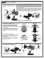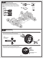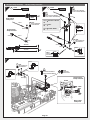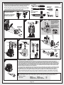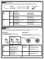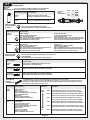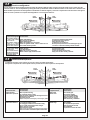
1
En
Es
Instruction Manual
Manual de instrucciones
High Performance RTR 1/8th Monster Truck
Hellfire RTR En Es
12005
Thank you
Thank you for selecting the HPI Racing Hellfire RTR! This kit is designed to be fun to drive and uses top quality
parts for durability and performance. The instruction manual you are reading was designed to be easy to follow yet
thorough in its explanations. HPI Racing wants you to enjoy driving your new Hellfire RTR. If you come across any
problems or need some help getting through a step, give us a call and we will do our very best to help you. You can
also contact us on the internet at www.hpieurope.com.
Cautions
To prevent any serious personal injury and/or damage to property, please be responsible when operating all remote controlled
models. Extra attention is called for when operating any glow fuel powered model. These models can exceed speeds of 30
m.p.h. and use highly poisonous and flammable fuels.
Before Running
●Please read manual (with parent, guardian or a responsible adult if necessary).
While Operating
●Please do not run on a public street, this could cause serious accidents, personal injuries and/or property damage.
●Please do not run near pedestrians or small children.
●Please do not run in small or confined areas.
Before Operating
●Make sure that all screws and nuts are properly tightened.
●Always use fresh batteries for your transmitter and receiver to avoid losing control of the model.
●Make sure no one else is using the same radio frequency as you are using.
●Please confirm the neutral throttle position.
After Running
●Shut off engine first, then turn off receiver switch and turn off transmitter last.
●After running Hellfire RTR, it is necessary to perform routine maintenance. Failure to do this can result in increased wear and damage to the engine and chassis.
Heat, Fire, and Fuel Safety
●Never use petrol in a glow engine. Use glow fuel specifically designed for model car engines.
●Do not run near open flames or smoke while running your model or while handling fuel.
●Always store fuel in a well ventilated place, away from heating devices, open flames, direct sunlight, or batteries. Keep glow fuel away from children.
●Glow fuel is flammable and poisonous. Glow fuel powered model engines emit poisonous vapors and gasses. These vapors irritate eyes and can be highly dangerous to your health.
●Be aware that some parts will be hot after operation. Do not touch the exhaust or the engine until they have cooled.
Gracias
Gracias por elegir el Hellfire RTR de HPI. Este kit a sido diseñado y fabricado con los mejores materiales para
lograr la máxima diversión y una gran resistencia . Este manual de instrucciones le servirá como guía para facilitarle el uso y mantenimiento del modelo. HPI Racing quiere que usted disfrute conduciendo su nuevo Hellfire RTR.
Si tiene cualquier problema al seguir estas instrucciones no dude en llamarnos o en visitar nuestra web
www.hpiracing.com
Precauciones
Para evitar posibles daños a las personas o las propiedades, sea responsable cuando use un modelo de Radio control. Es
necesario prestar una mayor atención cuando se trata de modelos propulsados por motores de gasolina. Este tipo de modelos
alcanzan velocidades cercanas a los 50 km/h. y utilizan combustibles tóxicos y altamente inflamables.
Antes de rodar:
●Lea el manual con atención ( con un adulto si es necesario)
Durante el uso;
●No ruede en calles abiertas, puede causar accidentes graves y daños a personas y/o propiedades.
●No ruede cerca de peatones o niños pequeños.
●No ruede en lugares pequeños o cerrados.
Antes de usarlo;
●Compruebe que todos los tornillos y tuercas están correctamente apretados
●Use siempre baterías en buen estado en su emisor y receptor para asegurar un correcto control del modelo.
●Asegúrese de nadie utiliza su misma frecuencia.
●Compruebe que el acelerador esta en neutro (relenti)
Después de rodar:
●En primer lugar pare el motor a continuación el receptor y por ultimo el emisor.
●Después de rodar con el Hellfire RTR es necesario realizar el mantenimiento. Un mal mantenimiento provoca desgastes
prematuros y puede dañar el motor o el chasis
Precauciones de seguridad:
●No use jamás gasolina en un motor glow. Use siempre combustible para modelismo.
●No ruede o manipule el combustible cerca de llamas , fuentes de calor o mientras fuma.
●Guarde siempre el combustible en lugares ventilados, lejos del calor,luz solar o baterías. Manténgalo lejos de los niños.
●El combustible glow es inflamable y tóxico. Los motores emiten gases tóxicos. Los gases pueden irritar los ojos o ser perjudiciales.
●Tenga cuidado ya que algunas partes están calientes al finalizar el uso. No toque el escape o el motor hasta que se haya enfriado.
Page 2
Contents
Contenidos
Section Sección Contents
2
‥‥‥‥‥‥ 3
‥‥‥‥‥‥ Overview
Vista general
4
‥‥‥‥‥‥ Start Up Guide
Guía de inicio
6
‥‥‥‥‥‥ 6
‥‥‥‥‥‥ 7
‥‥‥‥‥‥ 7
‥‥‥‥‥‥ 8
‥‥‥‥‥‥ 9
‥‥‥‥‥‥ 10
‥‥‥‥‥‥ 12
‥‥‥‥‥‥ 13
‥‥‥‥‥‥ 14
‥‥‥‥‥‥ 14
‥‥‥‥‥‥ 15
‥‥‥‥‥‥ 2-1
2-2
2-3
2-4
2-5
2-6
2-7
2-8
2-9
2 - 10
2 - 11
3
Maintenance Chart
Chassis
Wheel
Air Filter
Radio
Clutch
Gear Box / Differential
Front and Rear Differential
Center Gear Box
Center Differential
Shock
Servo
Engine
Setup Guide
4-1
4-2
4-3
4-4
4-5
4-6
4-7
4-8
4-9
4 - 10
4 - 11
4 - 12
4 - 13
4 - 14
4 - 15
4 - 16
4 - 17
4 - 18
5
Preparation for Running
Transmitter Preparation
Glow Plug Igniter Preparation
How To Control R/C Models
Linkage Setup
Starting Engine and Break In
Engine Tuning After Break In
Optional Tuning
Carburetor Factory Setting
Glow Plug
Troubleshooting
Maintenance
3-1
3-2
3-3
3-4
3-5
3-6
3-7
3-8
3-9
3 - 10
3 - 11
3 - 12
3 - 13
4
Page
Gracias
Contenidos
Thank you
Contents
1
2
Contenidos
Setup Chart
Ride Height
Camber
Droop
Sway Bar
Clutch
Shock Absorbers
Shock Mounting Position
Camber Link Location
Kick Up
Caster Angle
Steering
Front Toe
Front Inboard Angle
Rear Toe Angle
Rear Anti Squat
Wheelbase
Differentials
Exploded View
5-1
5-2
5-3
5-4
5-5
Chassis
Transmission
Front
Rear
Spare Parts List
Preparación para rodar
Preparación emisora
Preparación calentador bujías
Como controlar modelos R/C
Ajuste varillaje
Arranque y rodaje del motor
Ajustes tras el rodaje
Ajustes opcionales
Ajustes originales carburador
Bujía
Averías
Mantenimiento
Guía mantenimiento
Chasis
Ruedas
Filtro de aire
Radio
Embrague
Transmisión /diferencial
Diferenciales del/tras
Transmisión central
Diferencial central
Amortiguadores
Servo
Motor
Guía de ajustes
Tabla de ajustes
Altura libre
Angulo caída
Recorrido suspensión
Barra estabilizadora
Embrague
Amortiguadores
Posición amortiguadores
Ajuste tirantes suspensión
Angulo ataque del.
Angulo pivote
Dirección
Pinzamiento delantero
Pinzamiento trapecios del.
Pinzamiento trasero
Anti hundimiento trasero
Batalla
Diferenciales
Despiece
Chasis
Transmisión
Delante
Detrás
Lista recambios
Page 3
16
‥‥‥‥‥‥ 16
‥‥‥‥‥‥ 17
‥‥‥‥‥‥ 17
‥‥‥‥‥‥ 18
‥‥‥‥‥‥ 19
‥‥‥‥‥‥ 20
‥‥‥‥‥‥ 21
‥‥‥‥‥‥ 22
‥‥‥‥‥‥ 23
‥‥‥‥‥‥ 24
‥‥‥‥‥‥ 25
‥‥‥‥‥‥ 26
‥‥‥‥‥‥ 28
‥‥‥‥‥‥ 30
‥‥‥‥‥‥ 30
‥‥‥‥‥‥ 30
‥‥‥‥‥‥ 31
‥‥‥‥‥‥ 31
‥‥‥‥‥‥ 32
‥‥‥‥‥‥ 32
‥‥‥‥‥‥ 33
‥‥‥‥‥‥ 34
‥‥‥‥‥‥ 34
‥‥‥‥‥‥ 35
‥‥‥‥‥‥ 35
‥‥‥‥‥‥ 35
‥‥‥‥‥‥ 36
‥‥‥‥‥‥ 36
‥‥‥‥‥‥ 36
‥‥‥‥‥‥ 37
‥‥‥‥‥‥ 37
‥‥‥‥‥‥ 37
‥‥‥‥‥‥ 38
‥‥‥‥‥‥ 38
‥‥‥‥‥‥ 39
‥‥‥‥‥‥ 40
‥‥‥‥‥‥ 41
‥‥‥‥‥‥ 42
‥‥‥‥‥‥ 1
Overview
Components
Componentes
R/C Car
Coche R/C
Transmitter
Emisora
2013
Receiver Battery Pack 6.0 Volt
Batería receptor 6.0 volt
Included Items
Instruction Manual
Manual instrucciones
Z150
Antenna Pipe
Tubo de antena
2036 (US)
2037 (EU 2Pin)
2038 (EU 3Pin)
2039 (JP)
Compatible Charger
Cargador compatible
Spare Parts Bag
Bolsa recambios
Partes incluidas
Z950
Cross Wrench
Llave de cruz
70332
Glow Plug Wrench
Partes incluidas
86588
Multi Wrench (M18/M5.5/M3.6)
Llave múltiple
5.5
mm
8
mm
7
mm
5.5
mm
18
mm
3.6
mm
17
mm
Equipment Needed
Material necesario
74104 (EU 3Pin)
74105 (US)
74106 (EU 2Pin)
74107 (JP)
Glow Plug Igniter
Calentador
Screwdriver
Destornillador
Recommended Nitro Content
Tasa de nitro recomendada
9067
Fuel Bottle
Botella
combustible
20% - 25%
74151
HPI Racing Temp Gun
Termómetro HPI Racing
AA Alkaline Batteries
Baterías alcalinas AA
74318/74348 (US)
38704/38705 (JP)
Glow Fuel
Combustible glow
x8
Necessary for maintenance
Material para mantenimiento
Thread Lock
Fija tornillos
Needle Nosed Pliers
Alicates
Brush
Cepillo
Allen Wrench
Llave allen
1.5
mm
1.5mm
2
2.0mm
2.5
mm
2.5mm
3
3.0mm
mm
mm
x2
39014 (JP)
Oil Spray
Aceite en spray
30035 (JP)
Instant Cement
Pegamento instantáneo
Z164
Grease
Grasa
9062 (US,EU)
9063 (JP)
Nitro Car Cleaner
Limpiador motores
Z190
Air Filter Oil
Aceite filtro aire
Page 4
Rag
Trapo
Chassis Details
Detalles del chasis
Receiver Antenna
Antena receptor
Radio Box
Caja radio
Receiver Switch
Interruptor
Brake
Freno
ON
Fuel Tank
Deposito combustible
OFF
Sway Bar
Barra estabilizadora
Rear Gear Box
Transmisión trasera
Pull Starter
Arrancador
Front Gear Box
Transmisión delantera
Shock
Amortiguador
Engine
Motor
Drive Shaft
Cardan
Wheel Hub
Hexágono rueda
Engine Details
Center Gear Box
Transmisión central
Detalles motor
Air Filter
Filtro aire
Glow Plug
Bujía
Fuel Filter
Filtro combustible
Pull Starter
Arrancador
Fuel Tank Cap
Tapa deposito
combustible
Exhaust Header
Codo escape
Fuel Tank
Deposito
combustible
Carburetor
Carburador
Clutch
Embrague
Exhaust Pipe
Escape
Caution
Cuidado
Do not run on public streets or highways.
This could cause serious accidents,
personal injuries, and/or property damage.
Make sure everyone is using different
frequency (crystals) when driving together
in the same area.
No ruede en calles o carreteras. Puede
causar accidentes, daños a personas y/o
propiedades.
Asegúrese que usa una frecuencia
diferente al resto de usuarios cercanos.
Page 5
2
Start Up Guide
Guía de inicio
2-1
Please read the instructions before running.
Por favor, lea las instrucciones antes de rodar
Preparation for Running
Preparación para rodar
Body Removal
Retirar la carrocería
Receiver Battery Removal
Retirar la batería de recepción
Battery comes installed in the chassis.
Please unplug and remove before charging.
La batería esta colocada en el chasis. Desconectela y retírela
antes de cargarla
75106
2013
Receiver Battery Pack 6.0 Volt
Batería recepción 6.0v
75106
Receiver Battery Charging
Carga batería recepción
Charge time 4 hours.
Tiempo de carga 4 horas
2013
Receiver Battery Pack 6.0 Volt
Batería recepción 6.0v
2036 (US)
2037 (EU 2Pin)
2038 (EU 3Pin)
2039 (JP)
Compatible Charger
Cargador compatible
Plug into a wall outlet
Conéctelo a la red eléctrica
After charging disconnect the battery and unplug the charger from wall.
Una vez terminada la carga , desconecte la batería y el cargador
Receiver Battery Installation
Attention
Atención
Use included charger only for included receiver pack.
Do not use any other battery.
Charge time for discharged battery: 4 hours.
Do not charge battery for longer than 4 hours. This will cause over
heating and battery damage.
Do not charge other batteries with this charger. Serious damage
or injury can occur.
Keep battery out of reach of children. Keep battery away from water.
Use el cargador incluido solo para cargar la batería de recepción.
No lo use para ninguna otra batería.
Tiempo de carga para batería completamente descargada; 4 Horas.
No cargue la batería mas de 4 horas, puede sobrecalentarla
y dañarla.
No cargue otras baterías con este cargador, puede estropearlas
y provocar accidentes.
Mantenga la batería lejos del alcance de los niños. Evite el contacto
con el agua.
Instalación batería recepción
Connect and install receiver pack, then uncoil antenna wire, and pull
antenna wire through hole in battery cover. Secure the battery cover and
install antenna pipe.
Conecte e instale la batería de recepción, a continuación coloque la
antena a través del soporte en la tapa de batería. Coloque la tapa ,fíjela y
ponga el tubo de la antena.
Optional Charger
Z150
Z150
2013
Receiver Battery Pack 6.0 Volt
Batería recepción 6.0v
Cargador opcional
For extended running and less down time, we
recommend HB70452 GT Escape Charger.
Para lograr una mayor autonomía y una carga
mas rápida ,recomendamos el cargador
HB70452 GT Escape Charger.
HB70452
GT Escape Charger
GTエスケープチャージャー
12V DC power source necessary.
Two batteries can be charged at
the same time.
Es necesario conectarlo a una
fuente de 12v. Puede cargar dos
baterías a la vez
6122
This charger is powered by a standard 12V lighter
socket.
This charger is designed for Ni-MH battery.
Este cargador esta equipado con un conector
de mechero para coche. Permite cargar baterías
Ni-MH
Page 6
2-2
Transmitter Preparation
Preparación emisora
Steering Wheel Straight (Neutral)
Recto (neutro)
Volante dirección
Antenna
Antena
Extend the antenna to the maximum
length for best performance.
Left turn
Giro Izq.
Extienda la antena completamente para
lograr el máximo alcance.
AM Transmitter Crystal (TX)
Cristales emisora AM (TX)
The crystal can be replaced to change frequencies.
Note: You must also change receiver crystals!
Do not use FM crystals
El cristal puede cambiarse para variar la frecuencia.
Nota; Debe cambiar también el cristal del receptor.
No use cristales FM
Right turn
Giro Der.
To be used for
steering operation.
Uselo para dirigir
el modelo
AM Transmitter crystal (TX)
AM Receiver crystal (RX)
Battery Level Indicator
Indicador carga baterías
1 Steering Trim
3
Good Batteries
Baterías cargadas
Ajuste dirección
1
2
Low Batteries
Baterías descargadas.
To be used for trimming the steering
operation.
Uselo para ajustar la dirección
Throttle trigger
Gatillo acelerador
Brake
Power Switch
Interruptor
ON
2 Throttle Trim
Ajuste acelerador
Freno
Forward
Acelerar
Stop (Neutral)
Stop (neutro)
To be used for trimming the throttle
operation.
To be used for throttle operation.
Uselo para acelerar/frenar el modelo
OFF
Uselo para ajustar el acelerador
3 Steering Dual Rate
Reverse Switch
Inversores
Dual-rate dirección
Servo Factory Settings
Ajustes de fabrica
50%
To be used to adjust steering servo
rate and range.
Uselo para ajustar el recorrido del
servo del acelerador
Caution
Cuidado
Do not adjust more than 50% or you will
damage the steering servo.
Horizontal line shows 50% position. No ajuste el recorrido mas del 50%, puede
La línea horizontal indica el 50% dañar el servo de dirección.
Transmitter Battery Installation Instalación baterías emisora
Open battery cover at the bottom of transmitter.
Install batteries. Follow the direction of batteries
designated in the inside of battery box.
Abra la tapa inferior de la emisora. Coloque las
baterías. Siga las indicaciones marcadas en el
interior.
Attention
8x
AA Alkaline Batteries
Baterías alcalinas AA
2-3
Battery Cover
Tapa de baterías
Atención
Do not mix batteries of
different ages or types.
No mezcle baterías de distinto
tipo y antigüedad.
Glow Plug Igniter Preparation
Preparación calentador bujías
Glow plug igniter is neccesary for starting nitro engine.
These items are not included with your kit. They must be
purchased separately. Follow the instructions included with
your glow plug igniter and charger. If the glow plug igniter is not
fully charged, the engine will not start.
74104 (EU 3Pin)
You must charge before use.
74105 (US)
Cárguelo antes de usarlo.
74106 (EU 2Pin)
74107 (JP)
Glow Plug Igniter
Calentador de bujías
Compatible Charger
Cargador compatible
El calentador de bujías es necesario para arrancar el motor.
El calentador no esta incluido en el Kit. Debe comprarlo por
separado. Siga las instrucciones de su calentador y su
cargador. Si el calentador no esta completamente cargado ,
el motor no arrancara.
Remove glow plug igniter as soon as the engine is running.
Leaving it connected will drain the battery.
Retire el calentador en cuanto el motor arranque.
Si deja el calentador conectado puede descargarse.
Page 7
Glow Plug Igniter
Calentador de bujías
2-4
How To Control R/C Models
Como controlar modelos R/C
Activating R/C Unit
Conexión equipo radio
Turn on transmitter first, then turn on receiver.
Conecte primero el emisor y a continuación el
receptor
1
Make sure no one else is using the same radio frequency as you are using. Check the radio
system and range before every driving session. To properly check the range, have a friend hold
the truck with the engine off and walk to the farthest distance that you plan to operate your model.
Operate the controls to make sure the model responds correctly. Do not operate the model if there
is any problem with the radio system. If you switch on the R/C car first before the transmitter, you
may lose control of the R/C car.
Compruebe que nadie usa su misma frecuencia. Compruebe el correcto funcionamiento del
equipo de radio antes de empezar a rodar. Para verificar el alcance necesitara que un compañero
se aleje con el modelo , con el motor parado, a la máxima distancia a la que pretenda llegar. Mueva
los controles para comprobar el funcionamiento. No use el modelo si tiene interferencias. Si
conecta el receptor antes que la emisora puede perder el control del modelo.
3
Extend the antenna
Extienda la antena
ON
2
ON
Check Max. Range
Compruebe el alcance
Transmitter Operation Funcionamiento del emisor
Steering Wheel
Volante dirección
Turning the transmitter wheel left and right will make the
front tires of the car do the same. Turning the wheel a
small amount will make the model perform a wide turn.
Turning the wheel a large amount will make the model
perform a sharp turn.
Straight (Neutral)
Recto (neutro)
Straight (Neutral)
Recto (neutro)
Left turn
Giro Izq.
Right turn
Giro Der.
Left turn
Giro
Right turn
Giro Der.
Al girar el volante del emisor las ruedas de modelo giran
en el mismo sentido del volante. Si damos poco giro al
volante lograremos una curva abierta. Si damos un
mayor giro al volante lograremos una curva mas
cerrada.
Throttle Trigger
Gatillo acelerador
Forward
Adelante
Pull the throttle to drive forward and press it away for
brakes. The more you pull the throttle, the faster the car
will move forward.
Brake
Freno
Apretando el gatillo el modelo avanza , si lo empujamos
hacia delante el modelo frena. A mayor recorrido del
gatillo mayor velocidad.
Forward
Acelerar
Turning R/C Unit Off
Stop (Neutral)
Stop (neutro)
Apagado equipo radio
Turn off receiver first, then turn off transmitter.
Apague el receptor primero y a continuación el emisor
1
Stop (Neutral)
Stop (neutro)
Brake
Freno
2
OFF
OFF
If you switch off the transmitter first before the R/C car, you may lose control of the R/C car.
Si apaga antes el emisor que el receptor puede perder el control del modelo
Page 8
3
Retract the antenna
Recoja la antena
2-5
Linkage Setup
Ajuste varillaje
Important
If throttle linkage is not set up correctly the car may lose control after
the engine is started.
Si el varillaje del acelerador no esta bien ajustado , puede perder el
control del modelo al ponerlo en marcha
Trim adjusts neutral position of servo.
Make adjustments with the engine off.
Ajuste los servos en posición neutral.
Ajústelos con el motor parado.
Steering Trim Setup
Importante
Ajuste dirección
Turn steering trim to set tires in completely centered position.
Mueva el ajuste hasta lograr que las ruedas estén rectas.
Steering trim
Ajuste dirección
Steering Dual Rate
Dual-rate dirección
Do not adjust more than 50%
or you will damage the
steering servo.
No ajuste el recorrido mas
del 50%, puede dañar el
servo de dirección.
Throttle Linkage Setup
50%
Horizontal line shows
50% position.
La línea horizontal
indica el 50%
Ajuste varillaje acelerador
Turn throttle trim little by little and adjust rods as shown.
Mueva el ajuste paso a paso hasta lograr el ajuste indicado
Brake Adjustment Dial
Ajuste freno
Important
Importante
Throttle Servo
Servo acelerador
No brake drag at neutral.
Sin freno en neutral
Throttle trim
Ajuste acelerador
Optional Throttle Linkage Setup
Make sure servo arm is
parallel to servo case.
Compruebe que el brazo
esta paralelo a la caja.
1mm (0.04")
Carburetor
Carburador
Ajuste opcional del varillaje del acelerador
Remove air filter to adjust throttle linkage. After setup is complete, reinstall the air filter. See Section 3-4.
Retire el filtro de aire para ajustar el varillaje. Una vez terminado , vuelva a colocar el filtro. Vea la sección 3-4
Setting Full Throttle
Ajuste gas a fondo
Pull full throttle.
Make sure the carburetor is open.
Apriete al máximo.
Asegúrese que esta abierto totalmente.
Adjust until full open.
Ajuste hasta que
este abierto
Open
Abierto
Carburetor
Carburador
Setting Full Brake
Ajuste freno máximo
Push trigger to the full brake position.
Try pushing the car to make sure the
brake works.
Pulse el freno al máximo.
Empuje el modelo para comprobar que
el freno actúa.
Rear Brake Adjustment Dial
Ajuste freno trasero
Brake Adjustment Dial
Ajuste freno
More Braking
Mas freno
Less Braking
Menos freno
Front Brake Adjustment Dial
Ajuste freno delantero
Carburetor
Carburador
Important
Importante
Make sure there is no brake drag at neutral.
Compruebe que no esta frenado en neutral.
Page 9
2-6
Starting Engine and Break In
Puesta en marcha y rodaje
These instructions will explain the running procedure, how to prepare the car, turn on radio equipment, start the engine, break in the engine,
shut off the engine, and shut off the radio equipment. When starting the engine for the first time, you must perform the break in procedure.
Make sure no one is using the same frequency. Turn on transmitter first and receiver second. If you turn on the receiver first, it can cause you
to lose control of the car.
En estas instrucciones le indicamos el procedimiento de puesta en marcha, como preparar su modelo, como conectar su emisor, como
arrancar su motor , como hacerle el rodaje, como parar el motor y el equipo de radio. La primera vez que arranque el motor deberá seguir el
procedimiento de rodaje. Asegúrese que nadie usa su misma frecuencia. Conecte primero el emisor y a continuación el receptor, si conecta
primero el receptor puede perder el control de su modelo.
Preparation for engine start
Step 1
Preparación para arranque
Keep the wheels off the ground.
Mantenga las ruedas levantadas
Fill Fuel Tank
Step 2
Llene el deposito
Fill the tank completely with fuel. Use only 20 to 25%
nitro content fuel. Use high quality model car fuel only.
Using non-car fuels could void your warranty.
Recommended Nitro Content
Contenido de nitro recomendado
Llene completamente el deposito de combustible. Use
combustible con un 20 o 25% de nitrometano. Utilice
solo combustible para motores glow de calidad. No
usar combustible especifico le hará perder la garantía.
20% - 25%
74318/74348 (US)
38704/38705 (JP)
Glow Fuel
Turn on Radio System
Step 3
Conexión equipo radio
Make sure no one is using the same frequency. Turn on transmitter first, then turn on receiver.
Check the throttle and steering functions and check the radio range before starting engine. If
you switch on the R/C car first before the transmitter, you may lose control of the R/C car.
1
Compruebe que nadie usa su misma frecuencia. Conecte primero el emisor, a continuación
el receptor. Compruebe el funcionamiento del acelerador , la dirección y el alcance antes de
arrancar el motor. Si conecta primero el receptor puede perder el control del modelo.
Extend the antenna
3
ON
ON
2
ON
Step 4
Priming Engine
Cebado carburador
To prime the engine, use your finger to cover the exhaust tip. Pull the starter cord
several times until fuel reaches the carburetor and no bubbles are seen. Never pull the
starter cord more than 30cm (12”) max as it will damage the starter.
Para cebar el carburador, tape con un dedo la salida del escape. Tire del arrancador
varias veces hasta que llegue combustible sin burbujas al carburador. Si tira mas de
30 cm del tirador puede dañarlo.
Flooded engine
70332
NO!
Motor ahogado
If there is too much fuel in the cylinder,
the engine will not start.
Follow the step below to remove excess
fuel from the cylinder.
Si hay un exceso de combustible en el
cilindro, el motor no arrancara.
Siga estas instrucciones para retirar el
exceso de combustible.
Remove the glow plug and pull the starter
cord several times to remove excess fuel.
Reinstall the glow plug .
Retire la bujía y tire del arrancador varias
veces para vaciar el cilindro. Vuelva a
colocar la bujía
Page 10
12” 30cm MAX
OK!
Step 5
Glow Plug and Starter
Bujía y puesta en marcha
Attach the glow igniter to the glow plug. Start the engine by pulling the starter cord in
short pulls (no longer than 12”max). Remove the glow igniter as soon as the engine is
running.
Remove glow plug igniter as soon as the engine is running. If the glow plug igniter is
left connected while the engine is running, it will drain the battery and damage the glow
plug.
Conecte el calentador de bujía. Arranque el motor tirando del arrancador con tirones
cortos (no mas de 30 cm.) Retire el calentador en cuanto el motor arranque.
Si deja el calentador conectado con el motor en marcha puede gastar la batería y dañar
la bujía.
Attention
12” 30cm MAX
Atención
The engine must never be run without the air filter in place.
El motor debe arrancar siempre con el filtro de aire
Step 6
Break In
Rodaje
engines will feel tight at the top of their stroke when they are new or when they have not reached
1 HPI
their normal operating temperatures. The piston and cylinder sleeves are designed to achieve proper
running tolerances when they are properly broken in and are operating at the correct temperature. New
engines need a break in period of about 3 to 4 tanks of fuel before they can be run at full throttle, if not the
engine could be damaged. Break in should be performed on a flat level surface.
Los motores HPI dan sensación de estar clavados al final del recorrido del pistón cuando es nuevo y
aun no han rodado a su temperatura de uso. El cilindro y el pistón están diseñados para mantener las
tolerancias cuando han sido correctamente rodados y trabajan a su temperatura. Los motores nuevos
necesitan 3 o 4 depósitos de combustible antes de poder rodar a máxima velocidad, si no se realiza el
rodaje el motor puede dañarse.
2
After the engine starts, let it run with the wheels off the ground for one tank of fuel.
After the first tank, drive the car in a circle at half throttle for two tanks of fuel.
Una vez arrancado el motor, deje consumir un deposito con las rueda girando en el aire.
Después de este primer deposito consuma dos depósitos mas rodando en círculos.
Attention
20’ (6M)
Atención
New engines need a break in period of about 3 to 4 tanks of fuel before they can be
run at full throttle, if not the engine could be damaged. If the air filter falls off, you
must stop the engine immediately.
Los motores nuevos necesitan un rodaje de 3 o 4 depósitos antes de poder acelerar
al máximo, si no realiza el rodaje el motor puede estropearse. Si el filtro de aire se
suelta detenga el motor inmediatamente.
Step 7
Use a Rag
Engine Shut Off
Parar el motor
Usando un trapo
Pinch the Fuel Line
Use a rag to cover the exhaust tip. This
will stop the engine. Be careful! The
exhaust is extremely hot so be sure to
use a thick rag.
In extreme cases or emergencies
you can pinch the fuel line to stop
the flow of fuel to the carb.
Use un trapo para tapar la salida del
escape y parar el motor. Tenga cuidado,
el escape puede estar muy caliente,
asegúrese de usar un trapo grueso.
Step 8
Turning R/C Unit Off
Rag
Trapo
OFF
En caso de emergencia puede
pinzar el tubo de combustible del
carburador
Apagado equipo radio
Turn off receiver first, then turn off transmitter.
Apague primero el receptor y a
continuación el emisor
1
Presionando el tubo de combustible
2
OFF
If you switch off the transmitter first before the R/C car, you may lose control of the R/C car.
Si apaga antes el emisor que el receptor, puede perder el control de su modelo.
Page 11
3
Retract the antenna
Recoja la antena
2-7
Engine Tuning After Break in
Ajuste del motor después del rodaje
Important
Read this section carefully: Failure to follow these tuning steps could
result in damage to your engine, and void your warranty!
Lea esta sección con atención; No seguir estos ajustes puede
dañar su motor y hacerle perder su garantía
The carburetor is set up from the factory for break in (2-9). After break
in the carburetor must be tuned for high performance running.
El carburador esta ajustado de fabrica para el rodaje (2-9). Después
del rodaje el carburador debe ser reajustado para lograr las máximas
prestaciones.
Engine Features
Importante
Partes del motor
Carburetor Features
Heat Sink
Culata
Exhaust Outlet
Salida escape
Glow Plug
Bujía
Pull Starter
Arrancador
Partes del carburador
Low Speed Needle
Aguja de bajas
Mid Range Needle
Aguja de medios
Idle Adjustment Screw
Tornillo relenti
High Speed Needle
Aguja de altas
Carburetor
Carburador
Crankcase
Carter
Tuning for Optimum Performance
Ajustes para prestaciones óptimas
Step 1
Step 1
Step 2
Step 4
Paso 1
Turn the high speed needle clockwise in 1/8 turn
increments to lean out the fuel mixture for
increased top speed and throttle performance.
Drive the car to notice changes in speed and
throttle response.
Continue Tuning:
High Speed Needle
Aguja de altas
Step 3
STOP Tuning:
Use screwdriver to adjust
high speed needle.
Use un destornillador para
ajustar la aguja de altas
Step X
Caution
Cuidado
2 1/2 turn
MAX
2 1/2 turn MAX clockwise
from Groove
Apriete máximo 2 vueltas
y media de la señal
Fuel Mixture Tuning Tip
Siga cerrando la aguja en pasos de 1/8
(Máximo 2 vueltas y media)
Pare de ajustar:
Stop tuning and go to Step X if your engine shows
any of the following signs. (Engine is running too lean.)
Pare y vaya al Paso X si su motor muestra alguno
e estos signos ( el motor rueda muy seco)
At full throttle, there is no smoke
from the exhaust.
The engine hesitates or bogs.
Reduced top speed and loss of power.
Overheating
Temperatures above 250°F (120°C)
at the glow plug.
Gas a fondo el motor no humea
El motor no acelera continuo o "tose"
Reduce la velocidad o la potencia
Sobrecalentado.
Temperaturas de 120º en la bujía.
Step X
Paso X
If your engine is running lean, turn the needle
counter clockwise 1/4 turn to richen the fuel
mixture and repeat. Step 1
Step 4
Si su motor rueda demasiado seco, abra la aguja
de altas 1/4 de vuelta para enriquecer la mezcla
y repita Paso 1
Paso 4
Ajustes mezcla combustible
Engine temperature can tell you if the engine is
running lean or rich.
La temperatura del motor indica si la
carburación es rica o seca
Attention Atención
Adjust carburetor to keep the
operating temperature below 250°F.
Ajuste el carburador para mantener
una temperatura por debajo de 120º
Engine Temperature
Temperatura motor
Fuel Mixture Tuning
Ajuste mezcla
Danger
Peligro
危険範囲
Less Fuel = Lean
Menos gasolina = seco
250°F
(120°C)
Less Fuel = Lean
Menos gasolina = seco
Lean Fuel Mixture
Provides strong and efficient combustion and power,
but if you lean out too much the result is less
lubrication, more engine heat and shorter engine life.
Mezcla seca;
Tiene una mejor combustión y potencia, pero si esta
demasiado seco el resultado es una menor lubricación,
mayor temperatura y una menor duración.
230°F
(110°C)
Safe Range
74151
HPI Racing Temp Gun
Termómetro HPI Racing
Continúe ajustando:
Continue leaning the carb in Clockwise 1/8 turn
increments. (Maximum of 2 1/2 turns from flush.)
Step 4
Paso 4
Apriete la aguja de altas en pasos de 1/8 de
vuelta para empobrecer la mezcla y aumentar
así la velocidad y la respuesta al acelerador.
Ruede con el modelo para notar las
modificaciones.
More Fuel = Rich
Mas gasolina = graso
210°F Zona seguridad
(99°C)
Rich Fuel Mixture
190°F
(90°C)
Break in
Rodaje
Page 12
More Fuel = Rich
Mas gasolina = Graso
A slightly rich fuel mixture delivers a cooler running
temperature and more lubrication but with slightly
less power and longer engine life.
Mezcla rica:
Una mezcla mas rica disminuye la temperatura de
uso y mejora la lubricación, pero pierde potencia
aumentado la vida del motor.
Fuel Mixture Tuning Tips
Ajuste de altas
● Following
the tuning steps, tune the engine until its maximum performance is reached. While a lean motor will have higher performance, it can
lead to premature engine wear or failure. Use the following information to tune your engine to your driving conditions. Remember a slightly rich
setting is a safer setting.
● Engine temperature can tell you if the engine is running lean or rich. If you check the engine temperature, you can understand how to tune your
carburetor. Adjust carburetor to keep the operating temperature below 250°F. If the engine temperature goes over 250°F, the engine will be
damaged.
● If you turn the needle past the closed point, it will be damaged. Do not tighten past closed.
● If you lose the needle setting, you can reset the factory setting (See Section 2-9) and re-tune.
● Siguiendo estas instrucciones lograra que su motor alcance sus máximas prestaciones, Cuando un motor esta ajustado seco tiene mejores
prestaciones pero su desgaste es mayor y puede tener mas fallos. Use este manual para ajustar su motor a su manera de pilotar. Recuerde que
con un reglaje mas graso prolongamos la vida del motor.
● La temperatura del motor le indica si su ajuste es seco o graso. Controlando la temperatura de su motor entenderá como ajustarlo. Ajuste la
carburación para lograr una temperatura de trabajo por debajo de los 120º. Si la temperatura sobrepasa los 120º , el motor puede dañarse.
● No cierre en exceso la agujas, pueden estropearse. No apriete en exceso.
● Si duda del ajuste de la aguja, vuelva al ajuste de fabrica (vea sección 2-9) y reajuste de nuevo
2-8
Optional Tuning
Ajustes opcionales
Idle Adjustment Screw
Ajuste relenti
Idle should be set so that at neutral throttle position the engine is running without engaging the clutch and moving the car forward.
El relenti debe ajustarse de manera que con el motor en marcha el embrague no arrastre la campana y el coche avance.
Idle Adjustment Screw
Tornillo relenti
1mm (0.04")
Improper Idle Speed Setting:
Clutch engaged and wheels turning.
No!
Relenti mal ajustado , las ruedas giran
RPM Low
Menos RPM
RPM High
Mas RPM
The idle speed is set after the high-speed needle is adjusted and the engine is up to
operating temperature. To properly set the Idle Adjustment Screw, turn on your
radio system and set the throttle trim on the transmitter so that the throttle is in its
neutral position. This will ensure that the throttle slide is fully closed and resting
against the idle adjustment screw. Turn the idle adjustment screw counter
clockwise to reduce the idle speed, or clockwise to increase it. The idle speed
should be set high enough to keep the engine running smoothly but not engage the
clutch and turn the wheels. Too high of an idle speed will prematurely wear out the
clutch shoes and brake disk.
El ajuste del relenti debe realizarse después del de la aguja de altas y con el motor
caliente. Para lograr un ajuste correcto, conecte su emisor y coloque el ajuste de
acelerador en neutro. En esta posición logramos que el carburador este cerrado y
el tornillo actúe correctamente. El ajuste se realiza apretando el tornillo para
aumentar las revoluciones o aflójelo para disminuirlo. El ajuste correcto debe dejar
que el motor ruede suavemente pero sin que el embrague arrastre la campana y
mueva las ruedas. Un ajuste demasiado alto desgasta las zapatas de embrague en
exceso.
Low Speed Needle Adjustment
Low Speed Needle
Aguja de bajas
Ok!
Proper Idle Speed Setting:
Engine runs smoothly without wheels turning.
Ajuste correcto, el motor rueda suavemente y
las ruedas no giran
Ajuste aguja de bajas
More Fuel = Rich
If idle is unstable, adjust the low speed
needls to get a stable idle. Afterwards,
you need to readjust the idle adjustment
screw.
Less Fuel = Lean
Si el relenti es inestable. ajuste la aguja
de bajas para estabilizarlo. Luego
necesitara reajustar el relenti
Mas gasolina = Graso
Menos gasolina = seco
Flush (Factory Setting)
Enrrasado (ajuste de fabrica)
We recommend that you do not touch the Low Speed Needle. If adjustment is needed, the low-speed mixture is set after the high-speed needle is adjusted and the
engine is up to operating temperature. Set the needle flush (Factory Setting) with the carburetor body, this setting is ideal for breaking in and starting your
motor. For increased performance turn the needle in 1/8 turn increments; this will improve bottom end throttle response. To test your setting, place the car on
the ground and let the engine idle for 30 seconds then accelerate to 3/4 throttle. If there is a lot of white smoke and the car accelerates slowly, the mixture is
too rich. If the engine accelerates quickly and then sputters, the mixture is too lean. When the low-speed needle is set correctly the engine's throttle response
should be smooth and quick. CAUTION: Never turn in more than 2 turns from flush this will cause the engine to run too lean and may damage your engine! If
the Low Speed Needle is set too lean you will experience the following: Flame out at part or 3/4 throttle, overheating (temperatures above 280 F at the glow
plug). If your engine is running too lean, reset the Low Speed Needle to its factory setting (Flush) and start the tuning process again.
Le recomendamos que no toque la aguja de bajas. Si es necesario realizar algún ajuste, la aguja de bajas debe ajustarse después de la )aguja de altas y el
motor ya esta en temperatura de uso. Ajuste la aguja enrrasada ( ajuste de fabrica), este ajuste es el ideal para arrancar su motor y realizar el rodaje. Para
aumentar las prestaciones mueva la aguja en tramos de 1/8 de vuelta, este ajuste mejora la respuesta del motor a bajas revoluciones. Para comprobar que su
ajuste es correcto , deje el motor al relenti durante 30 segundos y a continuación acelere hasta 3/4 de recorrido del acelerador. Si el motor echa mucho humo
blanco y el coche acelera lentamente, el reglaje es muy graso. En cambio si el motor sube de vueltas y ratea, el ajuste es demasiado seco. Cuando el ajuste es
correcto , el motor acelerara progresivamente y sube rápido de vueltas. CUIDADO: Nunca cierre mas de 2 vueltas sobre el ajuste de fabrica, eso ara funcionar
el motor demasiado seco y estropeara su motor. Si la aguja de bajas esta demasiado cerrada notara lo siguiente: Rodando a 3/4 de gas , su motor se
sobrecalentara (temperaturas superiores a 150º en la bujía). Si su motor esta ajustado demasiado seco , coloque la aguja de bajas en el reglaje de fabrica y
reinicie el reglaje.
Page 13
2-9
Carburetor Factory Setting (Break In Setting)
Carburador ajustado de fabrica (Ajustes de rodaje)
High Speed Needle is set flush with groove, Idle Adjustment Screw, Low
speed needle and Mid Range Needle are designed to be set flush with the
carburetor body. This makes it easy to reset the carburetor to the Factory
Break In Setting if needed.
La aguja de altas esta a nivel de la marca al igual que el tornillo del relenti y
la aguja de medio régimen. Todas están diseñadas para que su posición
óptima sea a nivel de la marca. Esto ayuda a volver a los ajustes de fabrica
si es necesario.
Attention
Atención
Mid Range Needle
Aguja medios
High Speed Needle
Aguja altas
Flush
Enrrasado
When needle is over tightened, the
needle is damaged.
Flush with Groove
Enrrasado con
la marca
Idle Adjustment Screw
Tornillo relenti
Si aprieta las agujas en exceso
,pueden dañarse
2-10
Low Speed Needle
Aguja bajas
Glow Plug
Bujía
How Glow Plugs Work
Como funciona la
Unlike full sized car engines that use spark plugs and a distributor to fire the cylinders in the combustion cycle, glow engines rely
on glow plugs. In a Nitro engine, ignition is initiated by the application of a glow igniter. When the igniter is disconnected, the heat
inside the combustion chamber keeps the glow plug filament glowing, firing the next cycle, thereby keeping the engine running.
Ignition timing in a glow engine is automatic. At higher RPM’s the plug becomes hotter, firing the fuel/air mixture earlier. At lower
RPM’s the plug becomes cooler, firing the fuel/air mixture later. Since the glow plug performs so many important functions,
proper plug selection and maintenance are crucial to a properly running engine.
Al contrario de los coches reales que usan las bujías y el encendido para poner en funcionamiento los cilindros del motor , los
motores Glow usan unas bujías especificas. En un motor Nitro el encendido se realiza aplicando un calentador. Cuando se
desconecta el calentador, la temperatura en el interior del motor mantiene el filamento de la bujía incandescente, iniciando así
el siguiente ciclo. A mayores revoluciones la bujía aumenta de temperatura y quema la mezcla con mas rapidez. A menores
revoluciones la bujía se enfría y tarda mas en quemar la mezcla. Así pues la bujía tiene una vital importancia en el funcionamiento
del motor, una correcta elección y mantenimiento de la bujía mejora las prestaciones e su motor.
Proper Glow Plug Selection
Elección de la bujía
Proper glow plug selection depends on several factors: Fuel
type, nitro methane content, weather, and altitude can drastically
affect performance. Finding the best combination of fuel and
plug temperature for your driving condition is the key to getting
the maximum performance out of your Nitro Star Engine.
Outdoor Temp
Temperatura
Hot
Calor
La elección de la bujía correcta depende de varios factores: Tipo
de gasolina,porcentaje de nitrometano, clima y altitud afectan a
las prestaciones de su motor. Lograr la mejor combinación entre
el combustible la bujía y su manera de pilotar es la llave para
obtener las mejores prestaciones.
Glow Plug Characteristics
Características de la bujía
Cold plug will have better mid, high
RPM power and will last longer at high
temperature.
La bujía fria es mas eficaz a medias
revoluciones es mas resistente a altas
temperaturas
Glow Plug Cold R5
Bujía fria R5
Glow Plug Medium Cold R4
Bujía medio fria R4
Cold
Frío
Extending the Life of your Glow Plug
Glow Plug
Bujía
Hot plug will be easy to start and stable
for tuning. But will fail sooner at high
engine temperature.
Con la bujía caliente es mas fácil
arrancar el motor y mas estable a los
ajustes. Pero falla a altas temperaturas
Glow Plug Medium R3
Bujía media R3
Prolongar la vida de la bujía
To maximize and extend the life of your glow plug follow these simple tips;
●Remove the glow igniter when using more than 1/2 throttle or if the engine does not start after a few seconds.
●Do not run the engine lean, Lean conditions will overheat the plug causing the element to be damaged or fail.
●Use the best Fuel/Plug combination for your driving conditions.
●Use a fuel that has a lower nitro content.
Para mantener su bujía en buen estado y prolongar su vida útil , siga estos consejos:
●Retire el calentador si el motor no arranca en unos segundos.
●No use ajustes muy secos, si lo hace la bujía se daña rápidamente
●Busque la combinación entre gasolina y bujía que mejor se adapte a su pilotaje
●Use un combustible con poco porcentaje de nitro
When to Replace the Glow Plug
Cuando cambiar la bujía
Checking glow plug
Fuel and temperature will have an effect on the performance,
reliability, and life span of the glow plug and therefore it should Compruebe la bujía
be considered an expendable engine component. Aside from
Glow Plug
burnout or plug failure, there are several signs that can indicate
Bujía
the plug should be replaced.
●Plug filament/plug body is discolored or the surface is rough.
●Plug filament is distorted or bent.
●Engine cuts out when idling.
●Engine becomes difficult to start.
Hot!
Caliente
Pliers
El combustible y la temperatura afectan las prestaciones,
Alicates
respuesta y resistencia de su bujía , la bujía debe considerarse una
parte intercambiable de su motor. En caso de sobrecalentamiento
o fallo de la bujía existen unos síntomas que nos indican que
debemos sustituirla.
Glow Plug Igniter
●El filamento o el cuerpo de la bujía esta descolorido o la
Calentador
superficie esta rugosa
●El filamento esta retorcido o roto.
●El motor se para al ralenti
Page 14
●El motor es dificil de arrancar.
Filament
Filamento
Good Plug
Element glows
when tested.
Bujía en buen
estado.
El filamento brilla
Bad Plug
Element may be
damaged or broken if it
doesn’t light up
completely.
Bad Plug
Element is broken or
doesn’t light up at all.
Bujía en mal estado:
El filamento no se
ilumina
Bujía en mal estado.
El filamento no se
ilumina completamente
2-11
Troubleshooting
Averías
If R/C car does not move or you have no control, see below.
Si el coche no se mueve o no responde
Problem Problema
Engine Does Not Start.
Motor no arranca
Engine Starts Then Stalls.
El motor arranca y se para
Engine Running, But Car Doesn’t Move.
El motor funciona pero el coche no se mueve
Erratic Control.
Fallos de control
Cause Causa
Solution Solución
Section
Out of fuel.
Sin combustible
Fill the tank with fuel and prime engine.
Llene el deposito y cebe el motor
2-6
Air filter is blocked.
Filtro de aire obturado
Check air filter, clean or replace if necessary.
Compruébelo, limpielo o cámbielo si es necesario
3-4
Glow plug igniter not charged.
El calentador esta descargado
Charge glow igniter battery.
Cargue el calentador
2-3
Engine flooded.
Motor ahogado
Discharge fuel.
Vacíelo de combustible
2-6
Glow plug is bad.
Bujía en mal estado
Replace glow plug.
Cambie la bujía
2-10
Throttle isn’t adjusted properly.
Acelerador mal ajustado
See section 2-9 on carburetor factory setting then see section 2-7 on
engine tuning after break in.
Vea la sección 2-9 los ajustes de fabrica del carburador y a
continuación vea la sección 2-7 de ajustes después de rodaje.
2-9
Pullstart working properly?
¿Funciona el tirador?
Start engine by pulling the starter cord with quick, short pulls.
Arránquelo con tirones rápidos y cortos
2-6
Throttle servo is improperly set up.
Mal ajuste del servo del acelerador
Set servo to neutral and reset linkage according to radio and
model manufacture’s specifications.
Coloque el servo en neutro y reajuste el varillaje siguiendo
las instrucciones de la emisora.
2-5
Out of fuel.
Sin combustible
Fill the tank with fuel and prime engine.
Llene el deposito y cebe el motor
2-6
Air filter is blocked.
Filtro de aire obturado
Check air filter, clean or replace if necessary.
Compruébelo, limpielo o cámbielo si es necesario
3-4
Idle speed is set too low.
Relenti bajo
Adjust the idle speed.
Ajuste el tornillo de relenti
2-8
Throttle isn’t adjusted properly.
Acelerador mal ajustado
See section 2-9 on carburetor factory setting then see section 2-7 on
engine tuning after break in.
Vea la sección 2-9 los ajustes de fabrica del carburador y a continuación
vea la sección 2-7 de ajustes después de rodaje.
2-9
Engine is overheated.
Motor sobrecalentado
Allow engine to cool and then restart.
Deje enfriarlo y vuelva a intentarlo
2-7
Do you have clutch problem?
¿Problemas de embrague?
See section 3-6 on clutch maintenance.
Vea la sección 3-6 mantenimiento del embrague
3-6
Throttle servo is improperly set up.
Mal ajuste del servo del acelerador
Set servo to neutral and reset linkage according to radio and model
manufacture’s specifications.
Coloque el servo en neutro y reajuste el varillaje siguiendo las
instrucciones de la emisora.
2-5
Do you have a drivetrain problem?
¿Problemas de transmisión?
Check drivetrain for damage.
Compruebe la transmisión
Are the brakes stuck?
¿Frenos bloqueados?
See section 2-5. Make sure there is no brake drag at neutral.
Vea la sección 2-5. Compruebe que no esta frenado en neutro
2-5
Do you have clutch problem?
¿Problemas de embrague?
See section 3-6 on clutch maintenance.
Vea la sección 3-6 mantenimiento del embrague
3-6
Receiver battery capacity is low.
Batería receptor baja
Recharge reciever battery.
Recargue la batería
3-5
Gear mesh is incorrect.
Transmisión mal engranada
See section 3-9 on center gear box maintenance.
Vea sección 3-9, mantenimiento de la caja transmisión central
3-9
Do you have a drivetrain problem?
¿Problemas de transmisión?
Check drivetrain for damage.
Compruebe la transmisión
3-7 3-9
3-8 3-10
3-7 3-9
3-8 3-10
Weak batteries in transmitter and receiver. Install fresh battery and recharge battery.
Baterías descargadas en emisor y receptor Reemplace o recargue las baterías
3-5
Improper antenna on transmitter or model. Fully extend antenna.
Antena no extendida en transmisor o receptor Extienda la antena
3-5
Brake does not work.
Frenos no funcionan
2-5
See section 2-5 on linkage setup.
Vea sección 2-5 ajuste del varillaje
Page 15
3
Maintenance
Mantenimiento
After running you should clean the chassis and perform routine maintenance to keep the car in good running order.
Después de rodar limpie el chasis y siga las instrucciones de mantenimiento para dejar el coche preparado para los
siguientes usos
Necessary for maintenance
Material necesario
Screwdriver
Destornillador
Allen Wrench
Llave allen
1.5
mm
1.5mm
2
2.0mm
2.5
mm
2.5mm
3
mm
3.0mm
mm
3-1
Thread Lock
Fijatornillos
Needle Nosed Pliers
Alicates
7
39014 (JP)
Oil Spray
Aceite en spray
30035 (JP)
Instant Cement
Pagamento inst.
Z950
Cross Wrench
Llave en cruz
mm
Z190
Air Filter Oil
Aceite filtro aire
9062 (US,EU)
9063 (JP)
Nitro Car Cleaner
Spray limpiador
5.5
mm
86588
Multi Wrench
Llave múltiple
Z164
Grease
Grasa
5.5
mm
Brush
Pincel
Rag
Trapo
70332
Glow Plug Wrench
Llave de bujías
8
mm
18
mm
3.6
mm
17
mm
Maintenance Chart
Tabla mantenimiento
For maintenance schedule, refer to right side of the chart. After running, clean the chassis and check all moving parts for damage. If any
parts are broken or damaged, repair or replace them before the next run.
Regular maintenance is necessary to prevent damage to the car and maintain its performance.
Para la guía de mantenimiento siga la columna de la derecha. Después de rodar limpie el chasis y compruebe el estado de las partes en
movimiento. Si alguna parte esta dañada o rota, repárela o sustitúyala antes del siguiente uso.
El mantenimiento regular es necesario para evitar averías y mantener las prestaciones.
Reference Section
Sección
Maintenance Item
Mantenimiento de:
Maintenance Time
Tiempo de mantenimiento
3-2
page 17
Chassis Maintenance
Mantenimiento chasis
Clean the chassis after every run.
Limpie el chasis después de cada uso
3-3
page 17
Wheel Maintenance
Mantenimiento ruedas
Check the wheels after every run.
Compruebe las ruedas después de cada uso
3-4
page 18
Air Filter Maintenance
Mantenimiento filtro aire
Clean the air filter after every run.
Limpie el filtro de aire después de cada uso
3-5
page 19
Radio Maintenance
Mantenimiento radio
Check the battery before every run.
Compruebe las baterías antes de cada uso
3-6
page 20
Clutch Maintenance
Mantenimiento embrague
Maintain Clutch after each day’s running.
3-7
page 21
Gear Box / Differential Maintenance
Mantenimiento transmisión y diferencial
Maintain Gear Box after each day’s running.
Revise la transmisión de cada día de uso
3-8
page 22
Front And Rear Differential Maintenance
Mantenimiento dif. delantero y trasero
Maintain diff Gear Box after each day’s running.
3-9
page 23
Center Gear Box Maintenance
Mantenimiento transmisión central
Maintain Gear Box after each day’s running.
Revise la transmisión después de cada día de uso
3-10
page 24
Center Differential Maintenance
Mantenimiento diferencial central
Maintain diff Gear Box after each day’s running.
Revise la transmisión y el dif. después de cada día de uso
3-11
page 25
Shock Maintenance
Mantenimiento amortiguadores
Check the Shocks before every run.
3-12
page 26
Servo Maintenance
Mantenimiento servos
Check the linkage before every run.
Compruebe el varillaje antes de cada uso
3-13
page 28
Engine Maintenance
Mantenimiento motor
Maintain Engine after each day’s running.
Revise el motor después de cada día de uso
Compruebe el embrague después de cada día de uso
Compruebe los diferenciales después de cada día de uso
Compruebe los amortiguadores antes de cada uso
Page 16
Every 1 Tank
Cada deposito
Every 5 Tank
Every 10 Tank
Cada 5 depósitos Cada 10 depósitos
3-2
Chassis maintenance
Mantenimiento chasis
After running, clean the car and lubricate these points.
Replace damaged parts, check that all the screws are tight.
Brush
Pincel
Oil Spray
Aceite en spray
Después de usarlo,limpie el coche y lubrique los siguientes
puntos. Sustituya las partes dañadas y reapriete todos los
tornillos.
Rag
Trapo
Allen Wrench
Llave allen
1.5
mm
1.5mm
2
2.0mm
2.5
mm
2.5mm
3
3.0mm
mm
mm
3-3
Wheel maintenance
Mantenimiento ruedas
Wheel Removal and Installation
Montaje y desmontaje ruedas
Use 17mm glow plug wrench to remove and install wheels.
Use la llave de 17mm de la llave de bujías para desmontar/montar las ruedas
70332
Glow Plug Wrench
Llave de bujías
17
mm
Z659
Re-Glue Wheel
Pegado ruedas
Make sure the tire is secure on the wheel. Re-glue if necessary.
Asegúrese que el neumático esta bien pegado. Vuelva a pegarlo si es necesario
30035 (JP)
Instant Cement
Pegamento inst.
Use small amount to secure tire.
Use poca cantidad
Page 17
3-4
Air Filter Maintenance
Mantenimiento filtro aire
Proper Air Filter Maintenance
Mantenimiento correcto filtro aire
Dirt is the biggest enemy of a nitro engine and proper air filter maintenance is one of most important factors that
will affect your engines longevity. We recommend cleaning the element after every run. It is always a good habit
to check the element after every run to make sure it is properly seated in the filter body and that the body is fully
seated on the carburetor. Never run the engine without the air filter.
El polvo es el mayor enemigo de los motores glow, mantener un filtro de aire limpio es uno de los factores que
afectan a la duración de su motor. Recomendamos limpiarlo después de cada uso. Es importante comprobar
siempre el filtro antes de cada uso y verificar que esta correctamente instalado en su soportes y a su vez sólidamente fijado al carburador. Jamás ruede sin filtro de aire.
2.5mm
2.5
mm
6154
87199 c
87204 b
87509
87204 a
87199 b
Make sure the air filter is fully
seated on the carburetor and
secure it with a nylon tie strap
(6154).
Compruebe que el filtro esta
sólidamente fijado al carburador
con una brida de nylon (6154)
87199 a
Z224
2.5
mm
Z543
Cleaning the Filter Element
Limpieza filtro aire
Remove and clean the air filter with nitro fuel when dirty. Spray fuel
through the clean side to ensure proper dirt removal. Squeeze the filter
to remove excess fuel. To re-coat the air filter with oil, place the element
in a plastic bag with several drops of air filter oil. Using your fingers,
work the oil into the element making sure it is evenly distributed.
Retire y limpie el filtro de aire . Rocíe gasolina por la parte limpia del filtro
para asegurar una correcta limpieza. Seque el filtro del exceso de
gasolina. Para volver a aceitar el filtro de aire, coloque dentro de una
bolsa de plástico con aceite de filtro. Apriételo con los dedos asegurándose que el aceite esta correctamente repartido.
1
2
Z190
Air Filter Oil
Aceite filtro aire
Reinstalling the Filter Element
Recolocacion filtro aire
After properly cleaning the filter element make sure it is reinstalled correctly. Make sure there are no gaps
between the element and body. Make sure the filter is fully seated on the carburetor and secure it with a tie strap.
Never run the engine without the air filter.
Después de hacer limpiado el filtro instálelo correctamente. Asegúrese que no deja
tomas de aire entre el filtro y el carburador. Fíjelo con una brida de nylon.
No ruede jamás sin filtro de aire.
Attention
Atención
If the air filter falls off, you must stop the engine immediately.
Si el filtro de aire se cae, detenga el motor inmediatamente
6145
Make sure the air filter is
fully seated on the carburetor and secure it with a
nylon tie strap (6154).
Compruebe que el filtro
esta sólidamente fijado al
carburador con una brida
de nylon (6154)
6154
Nylon Strap
Brida nylon
Page 18
3
3-5
Radio Maintenance
Mantenimiento radio
Transmitter
Emisora
The crystal can be replaced to change frequencies.
Do not use same frequency as other cars.
Transmitter antenna must be extended.
Los cristales pueden cambiarse para variar la frecuencia.
No use la misma frecuencia que los demás usuarios.
Extienda la antena completamente
AM Transmitter crystal (TX)
Cristal emisor AM (TX)
AM Receiver crystal (RX)
Cristal receptor AM (RX)
AM Transmitter crystal (TX)
Cristal emisor AM (TX)
Battery level indicator
Indicador carga baterías
Good Batteries
Buena carga
Do not use FM crystals.
No use cristales FM
Band (US, EU)
Banda (US,EU)
1. BROWN
2. RED
3. ORANGE
4. YELLOW
5. GREEN
6. BLUE
Low Batteries
Baterías bajas
Band (JP) Frequency
Banda (JP) Frecuencia
MARRON (#80510)
ROJO
(#80510)
NARANJA (#80510)
AMARILLO (#80510)
VERDE
(#80510)
AZUL
(#80510)
Receiver and Servo
02.
04.
06.
08.
10.
12.
26.995 MHz
27.045 MHz
27.095 MHz
27.145 MHz
27.195 MHz
27.255 MHz
Exchange Batteries
Cambie las baterías
When the battery level indicator (LED) blinks
in red, replace the batteries with new ones
immediately.
Cuando el indicador (led) esta rojo, cambie
las baterías inmediatamente
HPI TF-3 (AM) Transmitter
Emisora HPI TF-3 (AM)
Receptor y servo
Receiver Connections
Conexión al receptor
If antenna is not positioned correctly, the receiver
will have low range or may not function.
See section 2-5 on linkage set up.
Receiver antenna must be extended.
Vea la sección 2-5 , ajuste varillaje
La antena debe estar extendida completamente
Si la antena no esta bien colocada, el receptor
puede tener menor alcance o no funcionar
80556 HPI RF-1
Receiver
Receptor
CH. 2 : Throttle Servo
Servo acelerador
80559 HPI SF-1
Antenna
Antena
Be sure to pull on the connector.
Pulling the wire can cause damage.
Asegúrese de tirar del conector.
Si tira del cable puede dañarlo
CH. 1 : Steering Servo
Servo dirección
80560 HPI SF-2
AM Receiver crystal (RX)
Cristal receptor AM (RX)
BATT : Receiver Battery
Batería del receptor
Receiver battery
2013
Receiver Battery
Batería receptor
Receiver Switch
Interruptor
80575 HPI SF-1
Batería receptor
Attention
Charge time 4 hours.
Tiempo de carga ,4 horas
2013
Receiver Battery Pack 6.0 Volt
Batería receptor 6.0volt
Atención
Use included charger only for included receiver pack.
Do not use any other battery.
Charge time for discharged battery: 4 hours.
Do not charge battery for longer than 4 hours. This will cause over heating
and battery damage.
Do not charge other batteries with this charger. Serious damage or
injury can occur.
Keep battery out of reach of children. Keep battery away from water.
After charging disconnect the battery and unplug the charger from wall.
Compatible Charger
Cargador compatible
Plug into a wall outlet
Conéctelo a la red
Use el cargador incluido solo para cargar la batería del receptor.
No lo use para otras baterías.
Tiempo de carga para baterías descargadas:4 horas
No cargue la batería mas de 4 horas, puede provocar sobrecalentamiento
y dañar la batería.
No cargue otras baterías con este cargador, puede provocar daños
Mantenga la batería lejos del alcance de los niños. Mantenga la batería
lejos del agua
Una vez acabada la carga desconecte la batería y el cargador de la red
Page 19
3-6
Clutch Maintenance
Mantenimiento embrague
Refer to Exploded View
Vea despiece 5-1
5-1
Maintenance Point
If clutch shoes or spring are damaged.
Revíselo si las zapatas o los muelles están estropeados
Change the gear ratio to suit the running conditions.
Ajuste el desarrollo en función del terreno
Gear Chart
Tabla desarrollos
Clutch Bell
13T
14T
15T
16T
51T
86511
16.4
15.3
14.3
13.4
52T
16.8
Standard
15.6
14.6
13.7
17.1
15.9
14.8
13.9
Spur Gear
Corona
77103
2.5
mm
Campana
86512
53T
86513
77104
77105
77106
87151 b
87151 a
2.5mm
77103
Thread Lock
Fijatornillos
Z694
B021
Z694
87151 b
B021
2.5
mm
Z543
Z845
Disassemble Clutch Shoe
Clean inside of clutch bell and reassemble.
Limpie el interior de la campana y vuelva a
montarla
Desmontaje zapatas embrague
Proper Spur Gear Mesh.
Engranaje correcto
Use flathead screwdriver
Use un destornillador plano
Screwdriver
Destornillador
x3
Assemble Clutch Shoe
Montaje zapatas embrague
Adjust the engine mount screws so
gears mesh smoothly.
Ajústelo con los tornillos del soporte
del motor para que gire suavemente
Adjust the engine placement for
proper gear mesh.
Use flathead screwdriver
Use un destornillador plano
Ajuste la posición del motor para
un correcto engranaje
Screwdriver
Destornillador
x3
Note Direction
Atención posición
2.5
mm
2.5
mm
94529
94529
87151 a
2.5
mm
87151 b
Page 20
2.5mm
3-7
Gear Box / Differential Maintenance
Mantenimiento transmisión y diferencial
Gear Box / Differential removal and installation
Refer to Exploded View
Vea despiece 5-3 5-4
5-3 5-4
Maintenance Point If parts are damaged.
Revíselo si hay partes dañadas
Montaje y desmontaje transmisión y diferencial
If parts are damaged, repair or replace them according to the instruction below.
Before removing bulkhead, loosen sway bar set screw. Rear gear box removal is same as front.
Si encuentra piezas dañadas o rotas sustitúyalas siguiendo estas instrucciones.
Antes de desmontar la tapa de la transmisión , afloje los tornillos de la barra estabilizadora.
La caja trasera se desmonta igual que la delantera
2.5
mm
2.5mm
1.5
mm
Z700
Grease
Grasa
Note Direction
Atención posición
1.5
mm
Z700
85512 5
2.5
mm
2.5
mm
94631
94641
85512 5
94641 Tapping Flat Head Screw M4x40mm
Tornillo avellanado autorroscante
2.5
mm
94633 Tapping Flat Head Screw M4x20mm
2.5
mm
94631
Tornillo avellanado autorroscante
94633
94631 Tapping Flat Head Screw M4x15mm
Tornillo avellanado autorroscante
Differential Gear removal and installation
Montaje y desmontaje diferencial
Make sure to tighten the set screws.
Compruebe que aprieta los tornillos
Do Not Over Tighten.
No apriete en exceso
1.5
mm
86506
Pin 2.5x14.6mm
Pasador 2,5x14,6mm
2.5
mm
Z412
Cap Head Screw M2.6x8mm
Tornillo hexagonal M2,6x8mm
Z740
Set Screw M5x4mm
Tornillo M5x4mm
Front
Delante 86566
Thread Lock
Fijatornillos
Note Direction
Atención posición
85501
86505
Grease
Grasa
2
mm
86565
Z721
Set Screw M4x4mm
Tornillo M4x4
B085
86523
86598
Rear
Detrás 86567
1.5
mm
1.5mm
2
2.0mm
2.5
mm
2.5mm
mm
86566 Center Front Drive Shaft 8x86mm
Front
Cardan central delantero 8x86mm
Delante
85501
Rear
Detrás
Page 21
86567 Center Rear Drive Shaft 8x112mm
Cardan central trasero 8x112mm
3-8
2
mm
Front and Rear Differential Maintenance
Mantenimiento diferenciales del/tras
Refer to Exploded View
Vea despiece 5-3 5-4
Point
If parts are damaged or oil level is low.
5-3 5-4 Maintenance
Revíselo si hay alguna parte dañada o si el nivel de aceite es bajo
2.0mm
87521 a
Z260
Pin 2.5x12mm
Pasador
2,5x12mm
87194
87521 c
6811
O-ring 6x9.5x2mm
Junta 6x9.5x2mm
87521 b
87521 b
87521 c
86522
87521 b
87521 c
87194
B085
87521 c
87521 b
Z164
Grease
Grasa
87521 a
86520
6811
Make sure to tighten the screws.
Asegúrese de apretarlos
O-ring 6x9.5x2mm
Junta 6x9,5x2mm
85500
Z260
Pin 2.5x12mm
Pasador 2,5x12mm
2
mm
2
mm
B085
86520
Z085
Z721
Set Screw M4x4mm
Tornillo M4x4mm
Flat Head Screw M3x15mm
Tornillo avellanado M3x15mm
Z164
Grease
Grasa
Differential oil
Aceite diferencial
Differential oil
Aceite diferencial
Front
Delante 7,000 wt
Rear
Detrás 7,000 wt
Fill to top of cross shafts with silicone diff oil.
Llénelo hasta cubrir los ejes con aceite de
silicona para diferenciales
Page 22
86099
3-9
Center Gear Box Maintenance
Mantenimiento transmisión central
Center Gear Box Removal and installation
2
mm
Refer to Exploded View
Vea despiece 5-1
Maintenance Point If brake parts are worn or damaged.
Revíselo si los frenos o las zapatas están dañadas
5-1
Montaje y desmontaje trans. central
2.0mm
Proper Spur Gear Mesh.
Engranaje correcto
2
mm
Z360
Button Head Screw M3x30mm
Tornillo cabeza redonda M3x30mm
Adjust the engine mount screws so
gears mesh smoothly.
Ajústelo con los tornillos del soporte del
motor para que gire suavemente
Adjust the engine placement for proper
gear mesh.
Ajuste la posición del motor para un
correcto engranaje
86514
86514
2.5
mm
2.5
mm
94529
94529
2.5
mm
Center Gear Box removal and installation
1.5
mm
1.5mm
2
mm
2.0mm
2.5mm
Montaje y desmontaje trans. central
1.5
mm Z700
Set Screw M3x3mm
Tornillo M3x3mm
86518
2
mm
85514
Z082
2
Flat Head Screw M3x8mm
Tornillo avellanado M3x8mm
mm
Z353
Button Head Screw M3x10mm
Tornillo cabeza redonda M3x10mm
4mm
86530
2mm
Rear
Detrás
Front
Delante
2 Z216
Button Head Screw M3x15mm
Tornillo cabeza redonda M3x15mm
mm
85502
86518
1.5
mm Z700
Set Screw M3x3mm
Tornillo M3x3mm
86516
86517
87515 a
87515 b
6.5mm
6.5mm
87515 a
R 87502 5
87515 a
F 87502 3
87515 a
87515 b
2 Z216
mm
Button Head Screw M3x15mm
Tornillo cabeza redonda M3x15mm
87515 a
Page 23
87515 b
x4
3-10
2
mm
Center Differential Maintenance
Mantenimiento diferencial central
Refer to Exploded View
Vea sección 5-1 5-2
5-1 5-2
Maintenance Point If parts are damaged or oil level is low.
Revíselo si hay alguna parte dañada o si el nivel de aceite es bajo
2.0mm
86519
87194
87521 c
B085
87521 b
87521 b
87521 c
87521 b
87521 c
87194
Z164
Grease
Grasa
86592
87521 c
87521 b
Z260
Pin 2.5x12mm
Pasador 2,5x12mm
6811
O-ring 6x9.5x2mm
Junta 6x9,5x2mm
87521 a
87521 a
6811
O-ring 6x9.5x2mm
Junta 6x9,5x2mm
Make sure to tighten the screws.
Asegúrese de apretarlos
85500
Z260
Pin 2.5x12mm
Pasador 2,5x12mm
2
2
mm
mm
Z721
B085
86519
Set Screw M4x4mm
Tornillo M4x4mm
Z085
Flat Head Screw M3x15mm
Tornillo avellanado M3x15mm
Z164
Grease
Grasa
Differential oil
Aceite diferencial
Differential oil
Aceite diferencial
Center
Central 15,000 wt
Fill to top of cross shafts with silicone diff oil.
Llénelo hasta cubrir los ejes con aceite de silicona
para diferenciales
Page 24
86099
3-11
Shock maintenance
Mantenimiento amortiguadores
75075
1
Refer to Exploded View
Vea sección 5-3 5-4
5-3 5-4
Z685
Silicone O-ring S4 (3.5x2mm)
Junta silicona S4 (3,5x2mm)
2
Washer 2.7x6.7x0.5mm
Arandela 2,7x6,7x0,5mm
5
86540
mm
Maintenance Point If oil is leaking or shock shaft or O-ring is damaged.
Revíselos si hay perdida de aceite o el vástago o juntas están dañados
Z661
87524
Lock Nut M2.6
ナイロンナット
86543
85510 3
86541
85510 13
Front
Delante 1.6mm x2 holes
Agujeros
5
mm
Z950
Cross Wrench
Llave en cruz
3
Piston
85231 4
Use masking tape to protect shock shaft. Screw
ball end all of the way onto the shock shaft.
Use cinta para proteger el vástago.
Enrosque la rotula al final del vástago
85510 12
1.4mm x2 holes
Agujeros
Rear
Detrás
4
Move the shaft up and
down slowly to remove
all air bubbles.
85510 8
Mueva el eje suavemente
para eliminar las
burbujas
85518 1
3
18
mm
87500
2
Shock Oil
Aceite amortiguadores
Front 20 wt.
Delante (#200)
Use a Rag.
Use un trapo
Rear
20 wt.
Detrás (#200)
1
86544
5
Shock Springs
Muelles amortiguador
Front 86550
Delante 18x80x1.5mm 10.5 COILS
Silver
Plata
Yellow
Rear 86554
Detrás 18x80x1.8mm 11.5 COILS Amarillo
Shock Clips
Clips tensores
85231 5
85231 7
86588
Multi Wrench
Llave multiusos
Front 85231 5 3mm x1
Delante 85231 8 5mm x1
85231 9 10mm x1
Rear
Detrás 85231 11 2mm x1
Page 25
x2
3-12
Servo Maintenance
Mantenimiento servos
Steering Servo Assembly
Refer to Exploded View
Vea sección 5-3
Maintenance Point If servo gears are damaged.
Revíselo si los piñónes del servo están dañados
5-3
Montaje servo dirección
2.0mm
2
mm
85515
2
mm
Z950
Cross Wrench
Llave en cruz
2
mm
5.5
mm
5.5
mm
Z216
Button Head Screw M3x15mm
Tornillo cabeza redonda M3x15mm
2
mm
87511
Z353
A132
Z663
LOCK NUT M3
Tuerca M3
Steering Servo
Servo dirección
80560 HPI SF-2
87511
Airtronics / JR / KO
2 Z082
Flat Head Screw M3x8mm
Tornillo avellanado M3x8mm
85507 11 Airtronics / JR / KO
23
85507 13 Hitec
86576
85515 5
24
Cone Washer
Arandela cónica
85507 15 Futaba / HPI SF
85515 5
25
2
KO
Button Head Screw M3x10mm
Tornillo cabeza redonda M3x10mm
mm
Servo Assembly
Futaba / Hitec / HPI SF
2 Z353
mm
86576
mm
Route wire through the hole.
Pase el cable por el orificio
Z082
85515 5
85515 1
85515 1
85515 1
Montaje servo
2
2.0mm
mm
Z083
2
Flat Head Screw M3x10mm
Tornillo avellanado M3x10mm
mm
Z353
Button Head Screw M3x10mm
Tornillo cabeza redonda M3x10mm
Optional
Opcional
Transponder Holder
Soporte transponder
2
mm
Z350
Button Head Screw M3x5mm
Tornillo cabeza redonda M3x5mm
2
mm
Z082
Flat Head Screw M3x8mm
Tornillo avellanado M3x8mm
87511
87511
Throttle Servo
Servo acelerador
80559 HPI SF-1
Route wire through the hole.
Pase el cable por el orificio
Steering Servo
Servo dirección
80560 HPI SF-2
85515 4
85515 4
Page 26
Throttle Linkage Assembly
1
1.5
mm
Montaje varillaje acelerador
1.5mm
2
2
mm
2.0mm
2
mm
Z085
Flat Head Screw M3x15mm
Tornillo avellanado M3x15mm
2
mm
18mm
Brake Linkage
Varillaje freno
x2
85507 7
85507 10 Airtronics / JR / KO
1.5
mm Z700
Set Screw M3x3mm
Tornillo M3x3mm
86571
23
Z224
85507 12 Hitec
24
85507 14 Futaba / HPI SF
86575
Throttle Linkage
Varillaje acelerador
85507 6
Z352
Button Head Screw M3x8mm
Tornillo cabeza redonda M3x8mm
25
86577
Flush
Enrrasado
86571
1.5
mm Z700
Set Screw M3x3mm
Tornillo M3x3mm
86575
45.6mm
85507 8
86574
85507 9
x1
57.9mm
50474
86575
8mm
Silicone Tube
Tubo silicona
0.5mm
3
86575
1.5
mm Z700
Set Screw M3x3mm
Tornillo M3x3mm
3.3mm
86575
2
mm
86576
Z082
Cone Washer
Arandela cónica
Flat Head Screw M3x8mm
Tornillo avellanado M3x8mm
2mm
86573
85507 3
Throttle Linkage
Varillaje acelerador
57.9mm
45.6mm
3.3mm
18mm
0.5mm
2mm
18mm
Brake Linkage
Varillaje freno
Page 27
3-13
NITRO STAR K4.6 HO ENGINE Maintenance
Mantenimiento motor Nitro Star K4.6 HO
Engine Maintenance
Mantenimiento motor
Drain all remaining fuel from the fuel tank. Use a fully charged glow igniter and try to restart the engine to burn any remaining fuel out of the lines.
After burning off the fuel, remove the glow plug and add several drops of after run oil, then crank the engine over to spread it throughout the
engine.
Vacíe el deposito de combustible. Arranque el motor para consumir el combustible de los tubos. Después de consumir ese combustible
desmonte la bujía y eche unas gotas de aceite After-run, haga rodar el motor para lubricar todo el motor.
If one way bearing or pullstart or connecting rod are damaged, please refer to
diagram below.
Si el rodamiento one-way del arrancador o el eje de unión están dañados ,
vea el despiece siguiente
Engine Features
Partes motor
Reference Section
Listado referencias
Break In
Linkage set up
Carburetor Set up
Carburetor Features
Heat Sink
Culata
Exhaust Outlet
Salida escape
Glow Plug
Bujía
Pull Starter
Arrancador
Rodaje
Ajuste varillaje
Ajuste carburador
2-6
2-5
2-7
Partes carburador
Low Speed Needle
Aguja bajas
Mid Range Needle
Aguja medios
Idle Adjustment Screw
Tornillo relenti
High Speed Needle
Aguja altas
Carburetor
Carburador
Crankcase
Carter
Exploded view
Despiece
15228
15237
15241
Dust Protection And O-ring Complete Set
Set completo de guardapolvo y juntas
15218
15285
15282
15283
1504
15260
15275
15217
15243
15214
15215
15266
15268
15271
15269
15274
Z700
15272
15213
15226
Z542
15233
15231
86077
15236
15245
15231
15234
94154
15244
Spare Parts List
Lista de piezas
Number
Qty.
Description
Referencia Cant. Descripción
Nitro Star K4.6 HO Engine With Pullstart
15204
x1
Motor Nitro Star K4,6 HO con arrancador
Glow Plug Cold R5
1504
x1
Bujía fria R5
Cylinder/Piston Set
15217
x1
Conjunto cilindro/pistón
Cylinder/piston/connecting Rod Set
15218
x1
Conjunto cilindro/pistón/biela
Connecting Rod
15213
x1
Biela
Piston Pin/retainer Set
15214
x1
Bulon / circlips
Retainer For Piston Pin
15215
x3
Circlips de bulon
Pullstart Assy. (W/o One-way Bearing)
15226
x1
Arrancador completo (sin rod.One-way)
Gasket Set For Cylinder (0.15mm/0.3mm)
15228
x1
Junta cilindro (0,15/0,3mm)
Lock Pin Set For Carburetor
15231
x1
Pasador fijación carburador
Pullstart Shaft Holder
15233
x1
Arrastre arrancador
Starting Shaft
15234
x1
Eje arrancador
Number Qty.
Description
Referencia Cant. Descripción
Cover Plate Set
15236
x1
Tapa trasera
Screw M3.5x16mm For Heatsink Head
15237
x4
Tornillos M3,5x16mm para culata
Dust Protection And O-ring Complete Set
15241
x1
Set completo de guardapolvo y juntas
Heatsink Head (Gray/K4.6 HO)
15243
x1
Culata (gris/K4,6 HO)
Crank Case (K4.6 HO)
15244
x1
Carter (K4,6 HO)
Crankshaft (K4.6 HO)
15245
x1
Cigüeñal (K4.6 HO)
Slide Carburetor Complete W/ Restrictors (Type KB)
15261
x1
Carburador completo con limitadores (tipo KB)
Uniball
15266
x1
Rotula
Low Speed Needle Valve With O-ring
15268
x1
Aguja bajas con juntas
Slide Valve
15269
x1
Barrilete carburador
Idle Adjustment Screw With O-ring
15271
x1
Tornillo relenti con juntas
Fuel Line Fitting/Washer Set
15272
x1
Toma de combustible/set de arandelas
Page 28
Number Qty.
Description
Referencia Cant. Descripción
High
Speed Needle Valve Holder
15274
x1
Soporte aguja altas
High Speed Needle Valve With O-ring
15275
x1
Aguja altas con juntas
Mid Range Needle Valve With O-ring
15282
x1
Aguja medios con juntas
Slide Carburetor Main Body W/restrictors(Type KB)
15283
x1
Cuerpo carburador con limitadores (tipo KB)
High Speed Needle Valve Set
15285
x1
Conjunto aguja altas
Collet 7x6.5mm (Brass/21 Size)
86077
x2
Cono cigüeñal (latón/tamaño 21)
Air Cleaner (21+ Size)
87198
x1
Filtro aire (tamaño 21+)
Air Cleaner Sleeve Set (For #87198)
87199
x1
Conjunto tubos filtro aire (para 87198)
Air Cleaner Foam Element Set (For #87198)
87204
x1
Elemento filtrante (para 87198)
Flat Head Screw M2.6x8mm (Hex Socket)
94154
x12
Tornillo avellanado M2,6x8mm (hexagonal)
Cap Head Screw M3x8mm
Z542
x12
Tornillo hexagonal M3x8mm
Set Screw M3x3mm
Z700
x6
Tornillo M3x3mm
Rebuilding The Engine
エンジンのリビルド
There comes a time when your engine just won’t provide the performance it
did when it was new. When that time comes a rebuild is in order. Follow the
steps below to disassemble, repair and then reassemble the engine.
El motor debe repararse si no tiene las mismas prestaciones que cuando
era nuevo. llegado el momento repárelo por orden. Siga los pasos que se
indican para desmontar, reparar y luego montar el motor.
Check engine compression.
If there is no compression,
the engine will not start.
OK!
2.5
mm
2.5mm
2
2.0mm
mm
70332
Glow Plug Wrench
Llave bujías
NG!
Z164
Grease
Grasa
8
mm
Compruebe la comprensión
del motor. Si no comprime,
el motor no arrancara.
1
2
8
mm
2.5
mm
3
Note:
Nota: Before removing the back
plate, rotate crankshaft so
the piston is at the top of its
stroke. If piston is in the
lower position, It will be
damaged.
1504
15237
Oil Spray
Aceite en spray
Thread Lock
Fijatornillos
Antes de desmontar la tapa
trasera, gire el cigüeñal
hasta que el pistón este
arriba. Si el pistón esta en
la posición mas baja puede
dañarse.
Thread Lock
Fijatornillos
2
mm
94154
4
1
5
15215
Note Direction.
Atención posición
15217
15228
2
15214
2.5
mm
15215
15217
Z542
15213
15236 c
Z164
Grease
Grasa
15236 a
0.1mm
15236 b
15234
NG!
Engine Assembly
6
Montaje motor
After completely disassembling the engine, examine the components to determine which parts need to be replaced.
Scratches on the crankshaft, or piston and sleeve are signs that dirt has entered the engine. Before reassembly, thoroughly
clean all parts to make sure they are free of foreign debris. Reassemble the engine in the reverse order of disassembly
(Step 6 - Step 1). Make sure to note the direction of the oil hole on the rod and the direction of the sleeve as they are critical
to proper engine function. As you assemble the engine, use a small amount of oil on each part to make sure they are well
lubricated and move freely. When you are finished, the new components will need to be broken in. Please turn to 2-6 and
follow the instructions to break in the new components.
Una vez desmontado completamente el motor, examine las piezas para determinar cuales deben ser sustituidas. Arañazos
en el cigüeñal , pistón o cilindro indican que ha entrado polvo. Antes de montarlo limpie todas las piezas y asegúrese que
giran libremente y que no tiene rebabas. Vuelva a montar el motor en orden inverso al desmontaje ( paso 6- paso 1) .
Asegúrese que la posición del agujero de lubricación de la biela y del cilindro son correctas ya que de ello depende el
correcto funcionamiento del motor. Use un poco de aceite en cada pieza para asegurar un movimiento suave. Cuando
finalice, los nuevos componentes necesitan rodaje. Vaya a la sección 2-6 y siga los pasos para rodar las nuevas piezas.
15222
After assembling the engine, follow the instructions on these pages to break in and set up your rebuilt engine.
Después de montar el motor siga las instrucciones para volver a realizar el rodaje y ajustarlo de nuevo.
Reference Section
Ver sección
Break In
Rodaje
Linkage set up
Ajuste varillaje
Carburetor Set up Ajuste carburador
Page 29
2-6
2-5
2-7
4
Tuning and Setup Guide
Guía de ajustes y puesta a punto
Tuning and Setup
Ajuste y puesta a punto
The Hellfire is the most tunable racing truck currently available. Most of the adjustments can be made in very small increments to fine tune your
handling and response. Use setup guide and the included setup sheets to start tuning your truck.
El Hellfire es el Truck racing con mayores posibilidades de ajustes. Muchos de los ajustes deben realizarse en pequeñas modificaciones para lograr
la mejor puesta a punto. Use la guía y las hojas de puesta a punto para comenzar la puesta a punto de su Truck.
4-1
Setup Chart
Guía puesta a punto
Before making changes to the setup of the truck, make sure the truck is in good running condition.
Making setup changes to a truck in poor condition may not have the expected results.
Antes de modificar la puesta a punto, compruebe que el Truck esta en condiciones de rodar.
Si modifica la puesta apunto con el Truck averiado , no lograra el resultado deseado.
Reference Section
Sección
Setup Item
Puesta a punto de:
Reference Section
Sección
Setup Item
Puesta a punto de:
4-2
page 30
Ride Height
Altura al suelo
4-11
page 35
Caster Angle
Angulo de pivote
4-3
page 31
Camber
Caídas
4-12
page 35
Steering
Dirección
4-4
page 31
Droop
4-13
page 36
Front Toe
Pinzamiento delantero
4-5
page 32
Sway Bar
Barra estabilizadora
4-14
page 36
Front Inboard Angle
Angulo interior trapecios delanteros
4-6
page 32
Clutch
Embrague
4-15
page 36
Rear Toe Angle
Pinzamiento trasero
4-7
page 33
Shock Absorbers
Amortiguadores
4-16
page 37
Rear Anti Squat
Anti-hundimiento trasero
4-8
page 34
Shock Mounting Position
Posición de amortiguadores
4-17
page 37
Wheelbase
Batalla
4-9
page 34
Camber Link Location
Tirantes de suspensión
4-18
page 37
Differentials
Diferenciales
4-10
page 35
Kick Up
Inclinación delantera
4-2
Ride Height
Altura al suelo
Use the shock clips to set the ride height of your car relative to the ground. Start with 8 mm of clips in the front and 12mm of clips in the rear (with
battery and full fuel tank).
You can experiment with chassis balance by keeping the car level or by raising the front or by raising the rear higher.
Use los clips tensores para ajustar la altura al suelo de su Truck. Comience con 8mm delante y 12mm detrás (con baterías y el deposito lleno).
Pruebe el equilibrio del chasis controlando la altura, subiendo el tren delantero o trasero.
Std. 85231 5 3mm
Front
Delante
85231 8 5mm
Front Ride Height
Altura delantera
Rear
Std. 85231 11 2mm
Detrás
85231 9 10mm
Rear Ride Height
Altura trasera
Page 30
Shock Clips
Clips tensores
85231 10
1mm
85231 11
2mm
85231 5
3mm
85231 8
5mm
85231 7
8mm
85231 9
10mm
4-3
Camber
Caídas
Use the upper link turnbuckles to adjust camber. Always use negative camber (tires leaning in).
More camber usually gives more progressive tire slipping, while less camber will give a more direct feeling.
Adjust according to tire wear. 1.5 degrees of negative camber is a good starting point. Use a gauge for precise measurement.
アッパーアームのターンバックルを調節してキャンバー角を調整します。ネガティブキャンバー
(タイヤが内側に傾く状態)
に調整してください。
キャンバー角を増やすと車体挙動が穏やかに、
キャンバー角を減らすとステアリングレスポンスが増しますので使用するタイヤに合わせて調節してください。
キャンバー角を1.5度から調節を始めるのが目安となります。正確にセッティングするためにキャンバーゲージの使用をおすすめします。
Rear
Detrás
Front
Delante
Camber Angle
Angulo caída
Front / Rear
Del/Tras
Characteristics
Características
More Negative Camber
Mas caída negativa
Front
Delante
Quicker reaction to steering input.
Respuesta mas rápida a la dirección
Rear
Detrás
Less rear traction on entry and mid-corner.
Menos tracción en la entrada/ media curva
Front
Delante
Slower reaction to steering input.
Respuesta mas lenta a la dirección
Rear
Detrás
More traction on entry and mid-corner.
If the wheel is too vertical, traction loss will be very sudden and difficult to control.
Mas tracción en entrada/media curva.
Si las ruedas están demasiado verticales, la tracción es menor, muy repentina y dificil de controlar.
Less Negative Camber
Menos caída negativa
4-4
Droop
Droop is the common R/C term for the relative amount of shock down travel. Limiting down travel (Droop) can change the response of your car.
The amount of travel will determine how quickly the car transitions in cornering. Less Droop will make the car react quicker. More droop will slow
down the response and allow more travel for bumpier tracks.
El Droop es un termino habitual en el R/C y se refiere al recorrido de las suspensiones. Limitando el recorrido de las suspensiones (Droop)
modificaremos la respuesta de nuestro modelo. el recorrido de las suspensiones determina lo rápido que el modelo puede pasar las curvas.
Menos Droop nos da unas reacciones mas rápidas. mas Droop nos deja un chasis mas lento y permite mayor recorrido en terrenos bacheados.
Front
Delante
Rear
Detrás
Set screw for droop adjustment
Tornillo ajuste recorrido
Set screw for droop adjustment
Tornillo ajuste recorrido
Wheel
Rueda
Droop Change
Modif. Droop
Front / Rear
Del/Tras
Characteristics
Características
Less droop
Menor Droop
Front
Delante
Less on power steering. Better for smaller jumps.
Menos dirección en aceleración. Mejor para pequeños baches
Rear
Detrás
Less off power steering.
Menos dirección al decelerar
Front
Delante
More on power steering. Better handling on rough tracks.
Mas dirección al acelerar. Mejor maniobrabilidad en circuitos rotos
Rear
Detrás
More rear traction. Better handling on rough tracks.
Mayor tracción trasera. Mejor maniobrabilidad en circuitos rotos
More droop
Mayor Droop
Page 31
4-5
Sway Bar
Barra estabilizadora
Adjust the stiffness of the front or rear anti roll bar by using a thinner or thicker wire and by adjusting the collar position.
Ajuste la dureza de las barras estabilizadoras cambiando el grosor de las barras o ajustando el ajuste de las rotulas de fijación
Sway Bar
Estabilizadora
86579 a
Std. 86579 a 2mm
標準 Black Negro
86579 b 2.5mm
86579 c 3mm
2mm
Softer
Blanda
Black Negro
Silver Plata
Gold Dorado
Stiffer
Dura
Softer
Blanda
Stiffer
Dura
Sway Bar Stiffness
Dureza estabilizadoras
Front / Rear
del/tras
Characteristics
Características
Softer
Blanda
Front
Delante
More front chassis roll.
More front traction.
Less rear traction.
Less off-power steering.
Mas inclinación delantera
Mas tracción delantera
Menos tracción trasera
Menos dirección al decelerar
Rear
Detrás
More rear chassis roll.
More rear traction.
Less front traction.
Less on-power steering.
Mas inclinación trasera
Mas tracción trasera
Menos tracción delantera
Menos dirección al acelerar
Front
Delante
Less front chassis roll.
Less front traction.
Less off-power steering at corner entry.
Faster steering response.
Menos inclinación delantera
Menor tracción delantera
Menor dirección al decelerar en entrada de curva
Reacción mas rápida de dirección
Rear
Detrás
Less rear chassis roll.
Less rear traction.
More front traction.
More on-power steering.
Faster steering response in high speed chicanes.
Menos inclinación trasera
Menos tracción trasera
Mas tracción delantera
Rápida respuesta de dirección en chicanes rápidas
Stiffer
Dura
4-6
Clutch
Embrague
Adjust the engagement characteristics of the clutch by changing the clutch spring or changing the orientation of the clutch shoes.
Ajuste el momento de enganche del embrague cambiando los muelles o la posición de las zapatas
Clutch Springs
Muelles embrague
Clutch Shoe Orientation
Posición zapatas
Adjust the engagement characteristics of the clutch by
using different clutch springs.
Ajuste el momento de enganche con los diferentes muelles
Adjust the engagement characteristics of the clutch by changing
the orientation of the clutch shoes.
Ajuste el momento de enganche cambiando la posición de las zapatas
86395
CLUTCH SPRING SET
Conj. muelles de embrague
Trailing shoes
Zapatas en arrastre
Leading shoes
Zapatas invertidas
Std.
Std.
87151
0.7mm
Black
Negro
Option 86395 a
Opción 0.9mm
Silver
Plata
Option 86395 b
Opción 1.0mm
Gold
Dorado
Clutch Springs
Muelles embrague
Characteristics
Características
Clutch Shoe Orientation
Posición zapatas
Characteristics
Características
Thinner
Fino
Clutch engages earlier at lower RPM.
More gradual acceleration.
Easier to drive but not as aggressive.
Trailing shoes
Zapatas en arrastre
Clutch engages more smoothly.
Better suited to slick track conditions.
Enganche mas suave.
Indicado para circuitos deslizantes
El embrague engancha a bajas RPM.
Aceleración progresiva.
Fácil de conducir pero no es agresivo.
Thicker
Duro
Clutch engages later at higher RPM.
More sudden acceleration.
Car is more aggressive.
Leading shoes
Zapatas invertidas
Clutch engages more aggressively.
Better suited to high traction tracks.
Enganche mas agresivo
Indicado para circuitos con agarre
El embrague engancha a mas RPM.
Aceleración mas violenta
Coche mas agresivo.
Page 32
4-7
Shock Absorbers
Amortiguadores
Shock Oil
You can use shock oils of different weights in the shock absorber.
Aceite
amortiguadores Use aceites de distinta densidad para ajustar la suspensión
Shock Oil
Aceite amortiguadores
Characteristics
Características
Thinner
Suave
Same as using larger pistons holes.
Igual que usando pistones de mayor paso
Thicker
Denso
Same as using smaller pistons holes.
Igual que usando pistones de menor paso
Piston Hole Size
Tamaño agujeros
pistones
Shock Oil
Aceite
amortiguadores
Front
Del.
Std. 20 wt.
(#200)
Rear
Tras.
Std. 20 wt.
(#200)
There are two pistons with different sized hole.
Dos posibles pistones con agujeros de distinto tamaño
Piston Hole Size
Tamaño agujeros pistones
Characteristics
Características
Smaller
Pequeños
Stiffer damping.
Slower chassis weight transfer.
Car reacts slower to input.
Less chance of bottoming out when landing when used with “thicker” oil.
Less chassis roll if used with “thicker” oil.
Use with thinner oil if track is rough.
Suspensión mas dura
Transferencia de peso mas lenta
Reacciones mas lentas
Menor posibilidad de rebote al saltar que usando aceite espeso
Menos inclinación del chasis que usando aceite mas ligero
Uselo con aceite mas ligero para circuitos rotos
Softer damping.
More traction.
Quicker chassis weight transfer.
Car reacts quicker to input.
More chance of bottoming out when landing if used with “thinner” oil.
More chassis roll if used with “thinner”oil.
Use with thicker oil if track is smooth.
Suspensión mas blanda
Mas tracción
Transferencia de peso mas rápida
Reacciones mas rápidas
Mayor posibilidad de rebote que usando aceite ligero
Mayor inclinación del chasis que usando aceite ligero
Use con aceite denso si el circuito es plano
1.4mm
Larger
Grandes
1.6mm
Piston Hole Type
Tipo de agujero
There are two different types of shock pistons that can be used
in the HELLFIRE.
En el Hellfire puede usar dos distintos tipos de agujeros.
Piston Hole Type
Tipo de agujero
Characteristics
Características
Straight
Recto
Compression and Rebound damping are the same.
Comprensión y extensión iguales
Taper Up
Cónico arriba
Less compression damping. More rebound damping.
Menor comprensión. Mas comprensión en extensión.
Taper Down
Cónico abajo
More compression damping. Less rebound damping.
Mas comprensión. Menos comprensión en extensión
Shock Spring
Muelles
amortiguador
Change the springs to control the attitude of your car on the track. Stiffer springs react more quickly, but may
not handle bumps. Try to use springs that keep the chassis level under cornering.
Cambie los muelles para ajustar el funcionamiento de su chasis en el circuito. Con muelles mas duros las
reacciones son mas rápidas , pero no funciona bien en terreno bacheado. Busque la suspensión correcta
para ajustar el nivel del chasis en las curvas
Shock Spring
Characteristics
Características
Softer
Blando
More chassis roll.
More traction.
Better on bumpy tracks.
More chance of bottoming out when landing.
Mas inclinación del chasis
Mas tracción
Mejor en terrenos bacheados
Mas posibilidades de rebote al saltar
Muelle amortiguador
Stiffer
Duro
Less chassis roll.
Less traction.
Car reacts quicker to input.
Better on smooth tracks.
Less chance of bottoming out when landing.
Menor inclinación del chasis
Menor tracción
Reacciones mas rápidas
Mejor en circuitos planos
Menor posibilidad de rebote en saltos
Parts Number
Referencia
Softer
Blando
Stiffer
Duro
Description
Descripción
86549
SHOCK SPRING 18x80x1.5mm 12.5 COILS (BLUE 4lbF/in / 71gF/mm)
Muelle amortiguador 18x80x1,5mm 12,5 espiras (azul 4lbsF/in 71gF/mm)
86550
SHOCK SPRING 18x80x1.5mm 10.5 COILS (SILVER 5.5lbF/in / 89gF/mm)
Muelle amortiguador 18x80x1,5mm 10,5 espiras (plateado 5.5lbF/in 89gF/mm)
86551
SHOCK SPRING 18x80x1.8mm 14.5 COILS (PINK 7lbF/in / 134gF/mm)
Muelle amortiguador 18x80x1,8mm 14,5 espiras (rosa 7lbF/in 134gF/mm)
86553
SHOCK SPRING 18x80x1.8mm 12.5 COILS (WHITE 9lbF/in / 159gF/mm)
Muelle amortiguador 18x80x1,8mm 12.5 espiras (blanco 9lbF/in 159gF/mm)
86554
SHOCK SPRING 18x80x1.8mm 11.5 COILS (YELLOW 10lbF/in / 177gF/mm)
Muelle amortiguador 18x80x1.8mm 11,5 espiras (amarillo 10lbF/in 177gF/mm)
86555
SHOCK SPRING 18x80x1.8mm 10.5 COILS (RED 11lbF/in / 196gF/mm)
Muelle amortiguador 18x80x1.8mm 10,5 espiras (rojo 11lbF/in 196gF/mm)
Page 33
4-8
Shock Mounting Position
Posición amortiguadores
You can change the shock mounting position by leaning the shocks at different angles, and also moving the shock closer or further from the
centerline of the car. You accomplish this by moving the shock top and bottom mounts to different locations on the shock towers and lower arms.
Puede cambiar la posición de loa amortiguadores inclinándolos en distintos ángulos y acercarlos o alejarlos del centro del chasis. Para lograrlo
basta con variar la posición en el soporte de amortiguadores o en los trapecios inferiores
Rear
Detrás
Front
Delante
Std. Position
Posición std.
Std. Position
Posición std.
Shock Position
Characteristics
Posición del amortiguador Características
More inclined moving in
on tower and/or moving
out on lower arm
Mas inclinado, variando la
posición en el soporte
hacia el interior y/o en los
trapecios hacia el exterior.
Less inclined moving out
on tower and/or moving
in on lower arm
Menos inclinados moviendo
hacia afuera la posición en
el soporte y/o hacia dentro
en el trapecio inferior
4-9
Softer initial damping
More progressive damping
Better lateral traction
Makes the handling more “forgiving”
Good for high-bite tracks, since it makes the car
more stable and easy to drive.
Suspensión inicialmente mas blanda
Amortiguación mas progresiva
Mayor tracción lateral
Conducción mas "permisiva"
Buena opción para circuitos con mucho agarre ya que
el coche se vuelve mas estable y fácil de conducir.
Stiffer damping
Less lateral traction
Makes the car more responsive
Better suited for tight, technical tracks
Suspensión mas dura
Menos tracción lateral
Coche mas rápido de reacciones
Mejor para circuitos virados y técnicos.
Camber Link Location
Posición tirantes superiores
To adjust the response of your chassis you can use a variety of camber link locations.
Para ajustar la respuesta de su chasis puede variar la posición de los tirantes superiores de suspensión.
Front
Delante
Rear
Detrás
Std. Position
Posición std.
Std. Position
Posición std.
Camber Link Position
Posición tirantes
Characteristics
Características
Camber Link Length
Longitud tirantes
Characteristics
Características
Higher Position
Posiciones superiores
More on-power steering.
Car responds slower to input.
Better on smooth, high-grip tracks with long fast corners.
Mas dirección en aceleración.
Respuesta mas lenta
Shorter link
Tirante corto
More camber gain.
More traction slightly.
Less steering and stability.
Mayor incremento de caída
Mejora un poco la tracción
Menor dirección y estabilidad
Less on-power steering.
car responds quicker to input.
Use in high-grip conditions to avoid traction rolling.
Use on tracks with quick direction changes.
Menor dirección al acelerar
Respuesta mas rápida
Longer link
Tirante largo
Less camber gain.
More stability.
Car responds to input slower.
Menor incremento de caída
Mas estabilidad
Respuesta mas suave del coche
Mejor en circuitos planos, de mucho agarre y con curvas largas y rápidas
Lower Position
Posiciones inferiores
Mejor en circuitos de mucho agarre para lograr mas tracción en apoyo
Uselo en circuitos con cambios rápidos de dirección
Page 34
4-10
Kick Up
Inclinación delantera
Adjust front kick-up of the front lower arms by changing the eccentric bushing in the plate at rear of the front bulk head.
Ajuste la inclinación delantera variando la posición de las excéntricas de la placa posterior de los trapecios delanteros
Chassis Kick Up = 7.0°
Inclinación delantera =7.0º
Suspension Mount Kick Up
Soportes para inclinación delantera
-2.0°
-1.5° Std.
標準
-1.0°
Front
Delante
7.0°
85504
Eccentric Bushing
Casquillo excéntrico
-0.5°
0°
Total Kick Up
Inclinación total
5.5°
=
Chassis Kick Up
Inclinación del chasis
7.0° +
Suspension Mount Kick Up
Soporte para inclinación delantera
-1.5°
Kick-up angle
Angulo inclinación
Characteristics
Características
Less kick-up
Menor ángulo inclinación
More weight transfer to the front of the chassis off-throttle or under braking.
Chassis compress or drops more off-throttle or under braking.
Better handling on bumpy tracks.
Less steering response.
Mayor transferencia de masas hacia delante en frenadas y deceleracion
More kick-up
Less weight transfer to the front of the chassis off-throttle or under braking.
Mayor ángulo inclinación Chassis compresses or drops less off-throttle or under braking.
Better handling on smooth tracks.
More steering response.
Menor transferencia de masas hacia delante en frenadas y deceleracion
4-11
El chasis se inclina mas al decelerar o al frenar
Mejor conducción en circuitos bacheados
Menor respuesta de dirección
El chasis se inclina menos al decelerar o al frenar
Mejor conducción en circuitos planos
Mejor respuesta a la dirección
Caster Angle
Angulo de pivote
Adjust the front caster angle by changing the caster brocks. The final caster also depends on kick-up setting.
Ajuste el ángulo de pinzamiento cambiando los porta-manguetas. El ángulo total varia segun el ángulo de inclinación (Kick-up)
Std. 85505
Caster Angle
Angulo de pivote
Characteristics
Características
Less Caster
Menos ángulo
More off-power steering into a corner.
Less on-power steering out of and in a corner.
Less straight-line stability.
Mas dirección en deceleracion a la entrada de las curvas
Menos dirección al acelerar a la salida de las curvas
Menor estabilidad en línea recta
Less off-power steering into a corner.
More on-power steering out of and in a corner.
More straight-line stability.
Menos dirección al decelerar a la entrada de las curvas
Mas dirección al acelerar al salir de las curvas
Mayor estabilidad en línea recta
More Caster
Mas ángulo
Total Caster Angle
Angulo total de pivote 18.5°
4-12
=
Caster Angle
Angulo pivote
13° +
Chassis Kick Up
Inclinación delantera
7.0° +
15°
85505
13°
Suspension Mount Kick Up
Soporte inclinación delantera
-1.5°
Steering
Dirección
The steering plate has been designed to give a full range of Ackerman running options.
La placa de dirección ha sido diseñada para tener una amplia gama de Ackerman.
Ackerman Angle
Angulo Ackerman
Characteristics
Características
Forward Holes
Posición delantera
Smoother steering response.
Car reacts smoothly to steering input.
Respuesta dirección suave
Reacciones a la dirección mas suaves
Rearward Holes
Posición trasera
More direct initial steering response.
Car reacts faster to steering input.
Mayor dirección inicial
Respuesta mas rápida a la dirección
Page 35
Std. Position
Posición std.
4-13
Front Toe
Pinzamiento delantero
Adjust by adjusting the length of the steering link turnbuckles.
Modifíquelo variando la longitud de los tirantes de dirección
Front Toe
Pinzamiento del.
Front Toe
Characteristics
Pinzamiento delantero Características
Toe-in
Mas
pinzamiento
Toe-in
Mas pinzamiento
More straight-line stability.
Less steering response.
More steering mid-corner and on-power corner exit.
Mas estabilidad en línea recta
Menos respuesta a la dirección
Mas dirección en media curva y al acelerar a la salida
Toe-out
Menos pinzamiento
Less straight-line stability.
More steering response.
Less steering on-power at corner exit.
Menos
pinzamiento Menor estabilidad en recta
Mas respuesta a la dirección
Menos dirección al decelerar y en la salida de las curvas
Toe-out
4-14
Front Inboard Angle
Angulo interior trapecios delanteros
Front inboard angle can be adjusted by changing the eccentric bushings.
El ángulo interior de los trapecios delanteros de modifica a través del casquillo excéntrico
Front Inboard Angle
Angulo interior
Characteristics
Características
Less Inboard Angle
Menos ángulo
More front stability.
Mayor estabilidad delantera
More Inboard Angle
Mas ángulo
More aggressive cornering.
Dirección mas agresiva
Less Inboard Angle
Menos ángulo
0° Std.
0.5°
85504
Eccentric Bushing
Casquillo excéntrico
1.0°
1.5°
More Inboard Angle
Mas ángulo
2.0°
86524
Front
Delante
4-15
Rear Toe Angle
Pinzamiento trasero
Rear toe angle can be adjusted by changing the eccentric bushings.
El pinzamiento trasero se ajusta mediante los casquillos excéntricos.
Rear toe angle
Pinzamiento trasero
Characteristics
Características
More rear toe-in
Mas pinzamiento
More stability under braking.
More stability on power at corner exit
Less top speed
Mayor estabilidad en frenada
Mas estabilidad al acelerar en salida de curva
Menor velocidad punta
Less rear toe-in
Menos pinzamiento
More steering
Less stability on power at corner exit
More top speed
Mayor dirección
Menor estabilidad al acelerar y en salida de curva
Mayor velocidad punta
Rear
Trasero
Less Rear Toe-in
Menos pinzamiento
2.0°
2.5°
85504
Eccentric Bushing
Casquillo excéntrico
3.0° Std.
3.5°
More Rear Toe-in
Mas pinzamiento
4.0°
86528
Page 36
4-16
Rear Anti Squat
Anti-hundimiento trasero
Adjust rear anti squat of rear lower arms by changing the eccentric bushings
Ajuste el anti-hundimeinto de los trapecios traseros mediante los casquillos excéntricos
85504
Anti squat angle Characteristics
Eccentric Bushing
Anti-hundimiento Características
Casquillo excéntrico
More Anti Squat
Mayor
anti-hundimiento
Less Anti Squat
Menos
anti-hundimiento
4-17
3.5°
More rear traction during acceleration.
Less rear traction off-power.
Good for smooth, slippery tracks.
Mas tracción trasera al acelerar
Menos tracción trasera al decelerar
Mejor para circuitos planos y deslizantes
3.0° Std.
2.5°
More rear traction off-power.
Less rear traction on-power.
Good for rough tracks.
Mas tracción trasera al decelerar
Menor tracción trasera al acelerar
Mejor para terrenos rotos
2.0°
1.5°
Wheelbase
Batalla
Front
Delante
Adjust the wheelbase by using the spacers on either side of the rear uprights.
Ajuste la batalla mediante los separadores en la mangueta trasera
Std.85508 3
Std.85508 1
4mm
1mm
Wheelbase
Batalla
Characteristics
Características
Shorter wheelbase
less spacers in front of rear upright
Batalla mas corta
Menos separadores delante de la
mangueta
Better rearward weight transfer during acceleration
More on-power traction.
Quicker off-power steering into corners.
Slight tendency to push on-power at corner exit.
better on tight, technical tracks.
Mayor peso en el eje trasero en aceleración
Mas tracción al acelerar
Dirección mas rápida en deceleracion a la entrada de curva
Mayor tracción al acelerar en salida de curva
Mejor en circuitos virados y técnicos
Longer wheelbase
more spacers in front of rear upright
Decrease off-power steering into sharp corners.
More stability.
Slower initial steering reaction (off-power).
Improves on-power steering at corner exit.
Better handling over bumps and ruts.
Better on more open tracks with high-speed corners.
Disminuye la dirección al decelerar en curvas cerradas
Mas estabilidad
Reacción mas lenta de dirección
Mejora la dirección al acelerar y en salida de curva
Mejor maniobrabilidad en baches
Mayor en circuitos abiertos y con curvas de alta velocidad
Batalla larga
Mas separadores delante de la
mangueta
4-18
Differentials
Diferenciales
Front Rear
Std.
Differential Oil
7000 wt.
Aceite diferencial Delante Detrás
Center Std.
15,000 wt.
Central
Adjust the characteristics of the differential by using thinner or thicker silicone oil.
Ajuste las características del diferencial variando la densidad del aceite del mismo
Differential
Diferencial
Front
Delante
Center
Central
Rear
Detrás
Oil Thickness
Characteristics
Densidad del aceite Características
Thinner
Ligero
Mejora la dirección dentro de las curvas
Improves steering into corners.
Si el aceite es demasiado ligero la dirección se volverá inestable
If oil is too thin the steering may become inconsistent.
Car can lose forward traction during acceleration out of corners. Puede perder tracción del. en la aceleración a la salida de las curvas
Thicker
Denso
Improves stability into corners during braking.
Improves steering on-power at corner exit.
Mejora la estabilidad en las frenadas
Mejora la dirección al acelerar a la salida de las curvas
Thinner
Ligero
Front wheels unload more during acceleration.
Increased off-power steering.
Easier to drive on rough tracks.
Las ruedas delanteras pierden contacto con el suelo en aceleración
Mejor dirección al decelerar
Fácil de conducir en terrenos rotos
Thicker
Denso
More all-wheel drive effect.
Better acceleration.
Increased on-power steering.
Better handling on high-bite, smooth tracks.
Mejor efecto 4x4
Mayor aceleración
Mejor dirección al acelerar
Mejor pilotaje en circuitos de buen agarre y planos
Thinner
Ligero
Improves cornering traction.
Improves steering into corner.
Mejora la tracción en curva
Mejora la dirección en curva
Thicker
Denso
Decreases rear traction while cornering.
Reduces wheelspin.
Menor tracción trasera en curva
Reduce perdidas de tracción
Page 37
Z354
85507
87076
87523
85516
86575
86571
Z224 Z082
85507
86571
86575
85507
86573
Z663
Z085
Z721
85516
86500
86173
Z663
86573
86575
86571
85507
85507
Z700
Z700
85507
Z352
Z700
86575
50474
Chassis Assembly
Montaje chasis
Exploded View
Despiece
5-1
5
Page 38
Z082
Z083
85515
87511
Z216
Z082
86570
Z224
85514
87504
Z663
Z224
Z353
Z083
85507
Z700
86574
86575
94631
87505
87511
Z082
94527
Z082
Z224
85514
87504
Z224
Z216
Z353
85515
85511
Z353
Z663
94527
94527
94527
85517
85510
Z082
Z663
85516
94527
Z082
Z353
Z082
Z082
Z082
Z083
Z353
Z082
Z663
Z082
85521
86559
Z740
Z216
85517
Z082
Z354
Z216
2013
85517
6163
85517
87022
6122
86596
94529
94529
75049
75049
86560
87506
6154
87040
87049
6154
87054
Z150
86598
86519
B085
Z412
85500
Z721
86523
85501
87521
85501
6811
Z260
B085
87194
87521
Z740
86565
6811
87235
86099
Z260
87521
Z721
Transmission Assembly
Montaje transmisión
Center
Differential Assembly
Montaje diferencial
central
5-2
Page 39
86566
86592
Z085
86517
85502
86514
86515
Z700
85511
Z353
86519
Z216
B085
94631
85502
86518
Z082
86518
Z360
87204
Z543
Z694
Z845
85502
77103
Z694
B021
86076
87151
6154
87521
86007
87509
86562
6154
87521
6811
Z260
87521
86561
86567
6811
86561
Z721
Z740
86565
15204
Z544
87235
86520
B085
Z085
86522
Montaje diferencial
del/tras
Z260
87521
86099
Front / Rear
Differential Assembly
85500
87194
87521
87151
87199
Z216
86514
85502
86515
86516
86530
Z700
87204
87199
Z224
Z543
B085
Z721
86520
B085
85501
86523
85501
86598
Z412
3151
4892
5-3
Page 40
85519
Z354
4892
85510
Z224
Z216
Z663
85519
Z538
85519
94630
94630
Z354
Z087
85519
85519
Z087
Front Assembly
Montaje delantero
85503
Z216
Z224
85510
94633
94631
94631
85503
Z700
86579
Z350
86531
87235
94633
86524
85504
87513
85512
85504
85509
Z350
85512
86580
Z547
A133
Z705
Z724
94641
Z350
85230
Z700
87514
86144
85230
Z350
Z721
87235
86531
86504
Z272
B085
Z659
Z740
86387
85506 L
86059
Z086
86508
87522
85507
85507
Z663
A132
Z216
86578
85515
Z082
Z353
Z083
Z663
94505
94505
Z216
86059
Z663
86508
B085
86531
Z216
86059
85230
85505 L
86568
Z663
85230
85504
94631
86507
85230
Z082
85515
A132
Z216
Z663
85507
Z083
Z663
86535
87511
Z353
86094
Z082
85507
86094
85514
Z086
86525
Z663
86059
85521
Z538
94633
93627
85230
Z663
Z224
Z547
85514
94633
94631
Z538
Z216
Z724
A133
Z705
86144
85512
85509
86580
Z547
86545
94630
86538
85503
94630
94641
85230
Z216
Z700
Z224
Z663
86545
86144
85230
87513
93627
Z663
86144
85230
Z721
86568
Z547
86504
86531
87514
94505
B085
85505 R
94505
Z234
Z700
Z234
Z663
B085
85506 R
Z272
86387
Z740
Z659
94529
86509
87522
B028
87522
B028
94529
Z082
94529
86509
B028
85507
B028
94529
Z082
85515
Z082
85230
87511
Z350
A133
85230
86504
87513
Z705
Z724
Z721
87235
85508
Z700
86580
87512
B085
Z216
85508
86387
Z740
Rear Assembly
Montaje trasero
B085
85508
Z272
Z659
5-4
Page 41
Z350
87513
94631
85509
86569
Z350
87512
85509
Z705
85503
Z350
Z547
85508
B085
Z272
93635
85230
86144
85508
Z740
Z659
86387
B085
85508
86144
85504
94630
94630
Plata
Rosa
Blanco
Silver
Pink
White
Red
87524
86543
86544
85231
Rojo
Yellow Amarillo
Azul
Blue
85231
86549
86550
86551
86553
86554
86555
Z085
85510
75075
85519
Z085
Shock Assembly
Montaje amortiguadores
86528
94631
85519
Z538
Z700
85503
Z234
Z234
85503
94631
94641
94641
86579
94633
86545
Z547
85504
94633
94630
85230
94633
94630
85512
86538
87235
Z721
86504
86569
Z663
Z224
86094
85514
Z538
Z700
86580
Z538
85512
A133
85230
94631
Z724
Z216
85526
85504
85521
94633
94633
86094
85514
86545
Z700
86540
85231
85231
85510
86541
85510
Z216
Z224 Z663
1.6T
1.4T
1.4
1.6
85518
85510 7
85510 10
85510 12
85510 13
87500
Z661
Z216
Z685
Z224
Z663
5-5
En
Parts #
Qty
2013
3151
4892
50474
6122
6154
6163
6811
75049
75075
75076
75106
77103
85230
85231
85500
85501
85502
85503
85504
85505
85506
85507
85508
85509
85510
85511
85512
85514
85515
85516
85517
85518
85519
85521
86059
86076
86077
86094
86099
86144
86173
86387
86500
86504
86507
86508
86509
86510
86514
86515
86516
86517
86518
86519
86520
86522
86523
86524
86525
86526
86528
86530
86531
86535
86538
86540
86541
86544
86545
86550
86554
86559
86560
86561
86562
86565
86566
86567
86568
86569
86570
86571
86573
1
2
2
1
10
10
5
8
8
12
8
20
1
2
1
1
1
1
1
1
1
1
1
1
1
1
1
1
1
2
1
1
2
1
1
4
1
1
6
10
4
1
2
1
2
1
2
2
1
2
2
1
1
2
2
2
1
1
1
1
1
1
1
4
2
1
1
2
4
2
2
2
1
1
2
1
1
1
1
1
1
1
2
2
Parts List
Refer to page 38 39 40 41 for parts contents.
Description
Parts #
STICK BATTERY PACK FOR RECEIVER (6V 1200mAh/Ni-MH)
DISH WHEEL BLACK (88x56mm)
AGGRESSORS TIRE S COMPOUND (139X74mm)
SILICONE TUBE 2x5x300mm
BODY PIN (MEDIUM)
NYLON STRAP (3.5x150mm/BLACK)
SERVO TAPE 20x100mm
O-RING 6x9.5x2mm (Black)
CONCAVE WASHER 4mm
SILICONE O-RING S4 (3.5x2mm)
O-RING S9 (8.5x1.5mm/BLACK)
BODY CLIP (6mm/BLACK)
RACING CLUTCH BELL 13 TOOTH (1M)
ROD END SET 7x45mm
SHOCK SPACER PARTS SET
DIFFERENTIAL CASE
DIFFERENTIAL SHELL SET
CENTER BULKHEAD SET
BULKHEAD SET
ECCENTRIC BUSHING SET
FRONT HUB CARRIER SET (BLACK)
FRONT SPINDLE CARRIER SET
STEERING AND THROTTLE SET
REAR HUB CARRIER SET
SUSPENSION ARM SET
SHOCK PARTS SET
FUEL LINE ACCESSORIES
BULKHEAD ACCESSORY SET
BODY MOUNT SET
SERVO MOUNT SET
CHASSIS BRACE
RADIO BOX SET
SHOCK CAP 20x21.6mm
BUMPER/SKIDPLATE SET
BULKHEAD BRACE SET
BALL 6.8x7.3x3mm (BLACK)
PILOT NUT 1/4-28X8.5mm (BLACK)
COLLET 7x6.5mm (BRASS/21 SIZE)
SCREW SHAFT M4x2x12mm (BLACK)
DIFF CASE WASHER 0.7mm
BALL 6.8x8x3mm
ALUMINUM MOUNT AND RETAINER SET
17mm HEX HUB ADAPTER
HELLFIRE MAIN CHASSIS
AXLE 8x11x36mm
STEERING PLATE (ALUMINUM/PURPLE)
STEERING BUSHING
STEERING POST
HELLFIRE ALUMINUM UPPER DECK
WAVE BRAKE DISC
BRAKE DISK/PLATE SET
BRAKE CAM A (REAR )
BRAKE CAM B (FRONT)
BRAKE LEVER
BRAKE OUTDRIVE CUP 13X31mm
DIFF SHAFT 13x30mm
BEVEL GEAR 42 TOOTH
BEVEL GEAR 10 TOOTH
FRONT LOWER SUSPENSION MOUNT FRONT
FRONT LOWER SUSPENSION MOUNT REAR
REAR LOWER SUSPENSION MOUNT FRONT
REAR LOWER SUSPENSION MOUNT REAR
CENTER BULKHEAD BRACE
FLANGE PIPE 4x8x6mm
TURNBUCKLE M4x80mm
SHOCK TOWER
SHOCK BODY (15x132-86mm)
SHOCK SHAFT 3.5X70mm
BALL 7x6mm
SHOCK MOUNT
SHOCK SPRING 18x80x1.5mm 10.5 COILS (SILVER 89gF/mm)
SHOCK SPRING 18x80x1.8mm 11.5 COILS (YELLOW 177gF/mm)
JOINT 7x35mm
ENGINE PLATE
ENGINE MOUNT
FLYWHEEL 7x34x10mm
COUPLING 14.5x18mm
CENTER FRONT DRIVE SHAFT 8x86mm
CENTER REAR DRIVE SHAFT 8x112mm
DRIVE SHAFT 8x134mm
DRIVE SHAFT 8x132mm
EXHAUST HANGER
BRAKE / THROTTLE ROD 2x68mm
BRAKE SPRING 2x9.5x0.5mm 9coils
86574
86575
86578
86579
86580
86588
86592
86596
86597
86598
87022
87040
87049
87054
87151
87193
87194
87198
87199
87204
87235
87500
87504
87505
87506
87509
87511
87512
87513
87514
87521
87522
87523
87524
93627
93635
94505
94527
94529
94630
94631
94633
94641
A132
A133
B021
B028
B085
Z082
Z083
Z085
Z086
Z087
Z150
Z216
Z224
Z234
Z260
Z272
Z350
Z352
Z353
Z354
Z360
Z412
Z538
Z543
Z544
Z547
Z659
Z661
Z663
Z685
Z694
Z700
Z705
Z721
Z724
Z740
Z845
Z950
Page 42
Qty
1
2
1
2
4
2
1
1
1
5
3
1
2
1
3
1
4
1
1
1
1
4
2
1
1
1
8
2
4
2
1
1
1
4
2
2
10
10
10
10
10
10
10
4
4
2
2
2
10
10
10
10
10
1
4
10
10
12
2
10
10
10
10
10
10
6
6
6
6
4
4
6
10
10
6
6
4
6
6
6
1
Description
THROTTLE SPRING 2.2x20x0.4mm 23coils
KNURLED COLLAR
TURNBUCKLE M3x31mm
SWAY BAR SET (2.0mm/2.5mm/3.0mm)
SWAY BAR BALL 5.8x10mm (PURPLE)
MULTI WRENCH (M18/M5.5/M3.6)
STEEL SPUR GEAR 52T
TUNED PIPE (HARD ANODIZED)
EXHAUST HEADER (HARD ANODIZED)
WASHER 13x16x0.2mm
FOAM TAPE 25x60mm
SILICONE EXHAUST COUPLING 12x18x30mm (PURPLE)
SHAPED EXHAUST GASKET (21 SIZE)
EXHAUST MANIFOLD SPRING 3.2x75x0.7mm x56
TEFLON CLUTCH SHOE/SPRING SET
4 BEVEL GEAR DIFFERENTIAL CONVERSION SET
SHAFT FOR 4 BEVEL GEAR DIFF 4x27mm
AIR CLEANER (21+ SIZE)
AIR CLEANER SLEEVE SET (FOR #87198)
AIR CLEANER FOAM ELEMENT SET (FOR #87198)
REBUILD KIT FOR UNIVERSAL DOGBONE
BLADDER 16x5mm (FLAT TYPE)
FUEL TANK BUSHING
FUEL TANK (150cc)
SWITCH DUST COVER (BLACK)
AIR FILTER ELBOW (90 DEGREE/21+ SIZE)
SERVO GROMMET
SUSPENSION SHAFT 3x45mm
SUSPENSION SHAFT 4x77.5mm
SUSPENSION SHAFT 3x43mm
BEVEL GEAR SET (20T/10T)
SERVO SAVER SET
INLINE FUEL FILTER
RUBBER BUMP STOP
TURNBUCKLE M5x60mm
TURNBUCKLE M5x75mm
CAP HEAD SCREW M4x12mm
FLAT HEAD SCREW M4x6mm (HEX SOCKET)
FLAT HEAD SCREW M4x10mm (HEX SOCKET)
TP. FLAT HEAD SCREW M4x12mm (HEX SOCKET)
TP. FLAT HEAD SCREW M4x15mm (HEX SOCKET)
TP. FLAT HEAD SCREW M4x20mm (HEX SOCKET)
TP. FLAT HEAD SCREW M4x40mm (HEX SOCKET)
FLANGED BALL 5.8x7mm
BALL 5.8x6mm
BALL BEARING 5x10x4mm
BALL BEARING 6x10x3mm
BALL BEARING 8x16x5mm
FLAT HEAD SCREW M3x8mm (HEX SOCKET)
FLAT HEAD SCREW M3x10mm (HEX SOCKET)
FLAT HEAD SCREW M3x15mm (HEX SOCKET)
FLAT HEAD SCREW M3x18mm (HEX SOCKET)
FLAT HEAD SCREW M3x20mm (HEX SOCKET)
ANTENNA PIPE SET
BUTTON HEAD HEX SOCKET SCREW M3x15mm
WASHER M3x8mm
CAP HEAD SCREW M2x5mm
PIN 2.5x12mm
PIN 3.0x17mm
BUTTON HEAD SCREW M3x5mm (HEX SOCKET)
BUTTON HEAD SCREW M3x8mm (HEX SOCKET)
BUTTON HEAD SCREW M3x10mm (HEX SOCKET)
BUTTON HEAD SCREW M3x12mm (HEX SOCKET)
BUTTON HEAD SCREW M3x30mm (HEX SOCKET)
CAP HEAD SCREW M2x10mm
CAP HEAD SCREW M3x25mm
CAP HEAD SCREW M3x10mm
CAP HEAD SCREW M3x12mm
CAP HEAD SCREW M3x20mm
NUT M12
LOCK NUT M2.6
LOCK NUT M3
WASHER 2.7x6.7x0.5mm
WASHER M5x10x0.5mm SILVER
SET SCREW M3x3mm
SET SCREW M3x10mm
SET SCREW M4x4mm
SET SCREW M4x8mm (ROUND POINT)
SET SCREW M5x4mm BLACK
CONE WASHER 3x10x3.5mm (PURPLE)
CROSS WRENCH (SMALL)
5-5
Es
Referencia Cant
2013
3151
4892
50474
6122
6154
6163
6811
75049
75075
75076
75106
77103
85230
85231
85500
85501
85502
85503
85504
85505
85506
85507
85508
85509
85510
85511
85512
85514
85515
85516
85517
85518
85519
85521
86059
86076
86077
86094
86099
86144
86173
86387
86500
86504
86507
86508
86509
86510
86514
86515
86516
86517
86518
86519
86520
86522
86523
86524
86525
86526
86528
86530
86531
86535
86538
86540
86541
86544
86545
86550
86554
86559
86560
86561
86562
86565
86566
86567
86568
86569
86570
86571
86573
1
2
2
1
10
10
5
8
8
12
8
20
1
2
1
1
1
1
1
1
1
1
1
1
1
1
1
1
1
2
1
1
2
1
1
4
1
1
6
10
4
1
2
1
2
1
2
2
1
2
2
1
1
2
2
2
1
1
1
1
1
1
1
4
2
1
1
2
4
2
2
2
1
1
2
1
1
1
1
1
1
1
2
2
Listado piezas
Vea la pagina 38,39,40,41 para ver el contenido
Descripción
Batería para receptor (6v 1200mAh/Ni-Mh)
Llanta Dish negra (88x56mm)
Neumáticos Agressor tipo S (139x74mm)
Tubo de silicona (2x5x30omm)
Clip carrocería (medio)
Brida Nylon (3,5x150mm negra)
Cinta doble cara 20x100mm
Junta 6x9.5x2mm (negra)
Arandela cóncava
Junta silicona S4 (3,5x2mm)
Junta S9 (8,5x1,5mm negra)
Clip carrocería (6mm negra)
Campana embrague 13d (1M)
Rotulas 7x45mm
Partes plástico amortiguador
Cuerpo diferencial
Juntas diferencial
Caja trans. central
Cajas transmisión
Casquillos excéntricos
Manguetas delanteras (negras)
Porta manguetas
Varillaje dirección y acelerador
Manguetas traseras
Trapecios
Partes amortiguadores
Accesorios tubo combustible
Accesorios cajas transmisión
Soportes carrocería
Soporte servo
Refuerzos chasis
Caja radio
Topan amortiguadores 20x21,6mm
Parachoques/placa deslizante
Refuerzo caja transmisión
Bola 6,8x7,3x3mm (negra)
Eje embrague M4x2x12mm (negro)
Cono 7x6,5mm (bronce/tamaño 21)
Eje roscado M4x2x12mm (negro)
Arandela diferencial 0,7mm
Bola 6,8x8x3mm
Soporte aluminio y restrictores
Hexágono 17mm
Chasis Hellfire
Eje 8x11x36mm
Placa dirección (aluminio púrpura)
Casquillo dirección
Poste dirección
Bandeja superior aluminio Hellfire
Disco de freno
Disco de freno/zapatas de freno
Leva freno A (tras)
Leva freno B (del)
Tirador freno
Vaso salida freno 13x31mm
Eje diferencial 13x30mm
Corona 42d
Piñon 10d
Soporte inferior del. trapecios delanteros
Soporte inferior tras. trapecios delanteros
Soporte inferior del. trapecios traseros
Soporte inferior tras. trapecios traseros
Refuerzo caja central
Tubo con arandela 4x8x6mm
Tirante M4x80mm
Soporte amortiguadores
Cuerpo amortiguadores (15x132-86mm)
Eje amortiguadores 3,5x70mm
Bola 7x6mm
Fijación amortiguadores
Muelle suspensión 18x80x1,5mm 10,5 espiras (plata 89gF/mm)
Muelle suspensión 18x80x1,8mm 11,5 espiras (amarillo 177gF/mm)
Eje 7x35mm
Soporte motor
Bancada motor
Volante embrague 7x34x10mm
Arrastre 14,5x18mm
Cardan central delantero 8x86mm
Cardan central trasero 8x112mm
Cardan 8x134mm
Cardan 8x132mm
Protector escape
Varillaje freno/acelerador 2x68mm
Muelle freno 2x9,5x0,5mm 9 espiras
Referencia Cant
86574
86575
86578
86579
86580
86588
86592
86596
86597
86598
87022
87040
87049
87054
87151
87193
87194
87198
87199
87204
87235
87500
87504
87505
87506
87509
87511
87512
87513
87514
87521
87522
87523
87524
93627
93635
94505
94527
94529
94630
94631
94633
94641
A132
A133
B021
B028
B085
Z082
Z083
Z085
Z086
Z087
Z150
Z216
Z224
Z234
Z260
Z272
Z350
Z352
Z353
Z354
Z360
Z412
Z538
Z543
Z544
Z547
Z659
Z661
Z663
Z685
Z694
Z700
Z705
Z721
Z724
Z740
Z845
Z950
Page 43
1
2
1
2
4
2
1
1
1
5
3
1
2
1
3
1
4
1
1
1
1
4
2
1
1
1
8
2
4
2
1
1
1
4
2
2
10
10
10
10
10
10
10
4
4
2
2
2
10
10
10
10
10
1
4
10
10
12
2
10
10
10
10
10
10
6
6
6
6
4
4
6
10
10
6
6
4
6
6
6
1
Descripción
Muelle acelerador 2,2x20.0,4mm 23 espiras
Casquillo
Tirante M3x31mm
Conjunto barra estabilizadora (2.0mm/2,5mm/3,0mm)
Rotula barra estabilizadora 5,8x10mm (púrpura)
Llave multiusos (M18/M5,5/M3,6)
Corona metálica 52d
Escape (reforzado)
Codo escape (reforzado)
Arandela 13x16x0,2mm
Cinta espuma 25x60mm
Junta unión escape 12x18x30mm (púrpura)
Junta salida escape (21)
Muelle escape 3,2x75x0,7mmx56
Zapatas embrague teflon/muelles
Conversión diferencial 4 satélites
Eje para diferencial 4 satélites
Filtro aire (21)
Tubos filtro aire (para 87198)
Elemento filtrante (para 87198)
Kit reparación junta homocinetica
Hoja 16x5mm (plana)
Casquillos deposito combustible
Deposito combustible (150cc)
Protector interruptor (negro)
Codo filtro aire (90ª /tamaño 21 +)
Silentblocs servo
Eje suspensión 3x45mm
Eje suspensión 4x77,5mm
Eje suspensión 3x43mm
Satélites/planetarios (20d/10d)
Salva servos
Filtro combustible
Juntas goma
Tirante M5x60mm
Tirante M5x75mm
Tornillo hexagonal M4x12mm
Tornillo hexagonal M4x6mm (hex)
Tornillo avellanado M4x10mm (hex)
Tornillo avellanado M4x12mm (hex)
Tornillo avellanado M4x15mm (hex)
Tornillo avellanado M4x20mm (hex)
Tornillo avellanado M4x40mm (hex)
Bola labiada 5,8x7mm
Bola 5,8x6mm
Rodamiento 5x10x4mm
Rodamiento 6x10x3mm
Rodamiento 8x16x5mm
Tornillo avellanado M3x8mm (hex)
Tornillo avellanado M3x10mm (hex)
Tornillo avellanado M3x15mm (hex)
Tornillo avellanado M3x18mm (hex)
Tornillo avellanado M3x20mm (hex)
Tubo antena
Tornillo cabeza redonda M3x15mm
Arandela M3x8mm
Tornillo cabeza redonda M2x5mm
Pasador 2,5x12mm
Pasador 3.0x17mm
Tornillo cabeza redonda M3x5mm (hex)
Tornillo cabeza redonda M3x8mm (hex)
Tornillo cabeza redonda M3x10mm (hex)
Tornillo cabeza redonda M3x12mm (hex)
Tornillo cabeza redonda M3x30mm (hex)
Tornillo hexagonal M2x10mm
Tornillo hexagonal M3x25mm
Tornillo hexagonal M3x10mm
Tornillo hexagonal M3x12mm
Tornillo hexagonal M3x20mm
Tuerca M12
Tuerca autoblocante M2,6
Tuerca autoblocante M3
Arandela 2,7x6,7xo,5mm
Arandela M5x10x0,5m Plateada
Tornillo M3x3mm
Tornillo M3x10mm
Tornillo M4x4mm
Tornillo M4x8mm (punta redonda)
Tornillo M5x4mm negra
Arandela cónica 3x10x3,5mm (púrpura)
Llave en cruz (pequeña)
21, William Nadin Way, Swadlincote
Derbyshire DE11 0BB
(+44)1823 229400