1
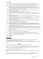
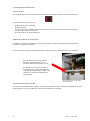
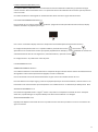
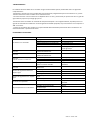
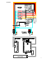
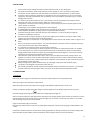
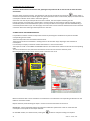
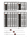
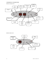
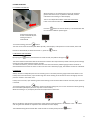
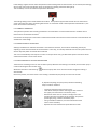
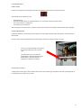
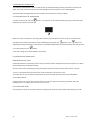
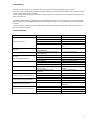
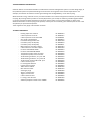
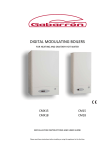
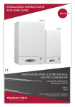
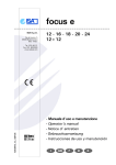
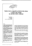
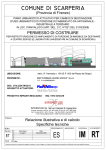
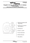
CALDERAS MODULANTES DIGITALES PARA CALEFACCIÓN Y AGUA CALIENTE SANITARIA DIGITAL MODULATING BOILERS FOR HEATING AND SANITARY HOT WATER CMX15 CMX18 CM15 CM18 INSTRUCCIONES DE INSTALACIÓN Y USO INSTALLATION INSTRUCTIONS AND USER GUIDE Lea estas instrucciones atentamente antes de instalar o utilizar el aparato por primera vez. Please read these instructions before installing or using this appliance for the first time. ÍNDICE 1 IMPORTANTE……………………………………………………………………………….. 3 2 INSTALACIÓN……………………………………………………………………………….. 4 3 PUESTA EN SERVICIO…………………………………………………………………… 4 3.1 CALEFACCIÓN………………………………………………………………. 4 3.2 AGUA CALIENTE SANITARIA…………………………………………. 5 4 LIMITACIÓN DE LA POTENCIA MÁXIMA………………………………………. 5 5 DESCRIPCIÓN DEL CUADRO DE MANDOS…………………………………….. 7 6 USO DE LA CALDERA…………………………………………………………………..… 8 6.1 ENCENDIDO / APAGADO………………………………………………. 8 6.2 BLOQUEO DEL TECLADO………………………………………………. 8 6.3 CALEFACCIÓN………………………………………………………………. 8 6.3.1 Termostato de ambiente…………………………….. 9 6.3.2 Modulación en calefacción………………………….. 9 6.3.3 Antibloqueo bomba aceleradora…………………. 9 6.3.4 Seguridad en calefacción…………………………….. 10 6.4 AGUA CALIENTE SANITARIA…………………………………………. 11 6.4.1 Ajuste de temperatura del A.C.S.………………… 11 6.4.2 Seguridad en A.C.S………………………………………. 11 7 MANTENIMIENTO…………………………………………………………………..……. 12 8 PROBLEMAS Y SOLUCIONES…………………………………………………..……. 12 9 DATOS TÉCNICOS…………………………………………………………………….….. 13 10 INFORMACIÓN MEDIO AMBIENTAL…………………………………………… 14 11 COMPONENTES PRINCIPALES…………………………………………………….. 14 12 ESQUEMAS…………………………………………………………………………………. 15 2 Gabarrón CM & CMX 1 IMPORTANTE • La garantía de la caldera no cubrirá cualquier daño causado por la no observancia de alguna de estas instrucciones. • Este manual debe ser conservado y dado a cualquier nuevo usuario. • Este aparato no está destinado a ser usado por personas (incluidos niños) cuyas capacidades físicas, sensoriales o mentales estén reducidas o carezcan de conocimiento del uso del aparato, salvo si son supervisados o instruidos por una persona responsable de su seguridad. • Compruebe que el voltaje de la placa de características de la caldera coincide con el voltaje de la red donde se va a conectar. • Cualquier reinstalación deberá ser efectuada por electricistas capacitados. El uso de estas calderas está prohibido en presencia de gases, explosivos u objetos inflamables. Las salidas y entradas de aire de la caldera aseguran el correcto funcionamiento y protegen de sobrecalentamientos. No se deben tapar nunca. Esta caldera debe ser desconectada de la red eléctrica antes de efectuar cualquier reparación en su interior. La caldera no debe ser instalada justo debajo de una toma de corriente. La caldera debe ser instalada de tal forma que los interruptores u otros controles no puedan ser tocados por alguien que esté usando el baño o la ducha. La instalación debe ser efectuada de acuerdo con la legislación eléctrica vigente. Este aparato está destinado a ser permanentemente conectado a una instalación fija. El circuito de alimentación de la caldera debe incorporar un interruptor de corte omnipolar con una separación de contactos de al menos 3 mm. El circuito de alimentación de la caldera debe incorporar un interruptor diferencial. Esta caldera debe ser conectada a tierra. Todos los modelos incorporan distintos dispositivos de seguridad. En caso de actuación de uno o varios de ellos acuda a la sección PROBLEMAS Y SOLUCIONES. La presencia en el aire de humo, polvo y polución puede, con el tiempo, manchar las paredes y zonas próximas al aparato. 0 26 DIMENSIONES Y CONEXION 5 30 30 760 A entrada agua fría 1/2" B desagüe válvula seguridad C salida A.C.S. 1/2" D retorno calefacción 3/4" E ida calefacción 3/4" F acometida eléctrica 830 45 F A BC D EB F D E 80 80 160 200 200 300 350 245 285 355 435 535 UPS 25-40 P (kPa) H(m) 40 4 3 20 2 1 0 0 0 0 0 0.5 1.0 20 1.5 0.5 2.0 2.5 3.0 3.5 1 40 60 4.0 4.5 3 Q(m /h) (l/min) Curvas de trabajo de la bomba aceleradora. 3 2 INSTALACIÓN Asegurarse que la tensión disponible en red, coincida con la marcada en la placa de características. La instalación eléctrica debe cumplir la legislación vigente. La sección de los conductores de alimentación debe ser suficiente para la potencia nominal o la potencia a la que se haya limitado la caldera. Instalar las protecciones eléctricas necesarias que indica la normativa vigente. En caso de no cumplir estas normativas, el fabricante no se hace responsable de los daños físicos o materiales que puedan ocurrir. Es necesario instalar la caldera de forma que ésta pueda separarse en todos los polos de la red eléctrica con un ancho de apertura de contacto de 3 mm como mínimo. Las conexiones hidráulicas al circuito de calefacción y A.C.S. deben de realizarse respetando la ida y el retorno marcados en la caldera. Instale purgadores en los radiadores y puntos altos de la instalación. En los modelos CM18 y CM15 instale una llave de llenado para el circuito de calefacción, lo más cercana posible a la caldera. En los modelos CMX18 y CMX15 la llave de llenado, está incorporada dentro de la caldera. En el punto más bajo de la instalación, colocar la llave de descarga para poder vaciar la instalación totalmente en caso necesario. Recomendamos conducir al desagüe la válvula de seguridad contra sobrepresión del circuito de calefacción, 2 a fin de evitar derrame de agua en caso de que la presión exceda de 3 kg/cm . Sólo para los modelos CMX: Es imprescindible conducir a un desagüe la válvula contra sobrepresión del 2 calderín de A.C.S. tarada a 7 kg/cm . 2 Si la presión de la red sobrepasa los 5 kg/cm se recomienda colocar un reductor de presión en la tubería a la salida del contador de la instalación de la vivienda. Es imprescindible conectar la caldera a una buena toma de tierra. La caldera puede ser comandada por una regulación externa, por ejemplo, termostato de ambiente o cronotermostato de ambiente. Este será conectado a los bornes en la placa electrónica una vez suprimido el puente existente entre ambos bornes. (Ver esquema eléctrico). Para que funcione el sistema modulante es imprescindible el uso de regulación externa. La instalación deberá realizarse de forma que se faciliten los trabajos de mantenimiento y reparación. Las conexiones hidráulicas se realizarán mediante racores, con el fin de facilitar la desconexión de la caldera del circuito. De no respetar estos aspectos de instalación, el Servicio Técnico no estará obligado a intervenir en la reparación de la caldera. Antes de realizar cualquier operación en el interior de la caldera, no olvidar desconectar la alimentación eléctrica. Esta caldera no está diseñada para su instalación a la intemperie. Si la instalación de calefacción incluye válvulas termostáticas hidráulicas o controladores de zona automáticos hay que evitar en todo momento que la circulación de agua pueda verse interrumpida, lo que ocasionará la actuación del termostato de seguridad. 3 PUESTA EN SERVICIO 3.1 CALEFACCIÓN Verificar que los puntos de desagüe situados en la parte baja de la instalación están perfectamente cerrados. Abrir los purgadores de la instalación y de la caldera. Abrir la llave de llenado hasta que el hidrómetro marque entre 1 y 1,5 bar, aproximadamente. Cerrar los purgadores de la instalación cuando empiece a fluir el agua por ellos. El purgador de la caldera no debe cerrarse. Encender la calefacción pulsando la tecla se iluminará el display de calefacción. Seleccionar una consigna superior a la temperatura indicada en el display de calefacción y comprobar el consumo una vez se encienda el indicador de funcionamiento de las resistencias de calefacción. El A.C.S. es prioritario, si el A.C.S. está conectado y consumiendo no podrá verificar este punto. Purgar la instalación nuevamente si fuese necesario. Reponer las posibles pérdidas de presión, abriendo la llave de llenado hasta que el hidrómetro marque entre 1 y 1,5bar. Si la caldera ha incluye la opción de suelo radiante (solicitada al hacer el pedido) el termostato de seguridad de calefacción actuará a 80°C y la temperatura de consigna de calefacción no podrá superar los 50°C. 4 Gabarrón CM & CMX 3.2 AGUA CALIENTE SANITARIA (A.C.S.) Proceder al llenado completo del depósito acumulador de 50 litros, abriendo un grifo de la instalación del A.C.S. para sacar el aire del acumulador de agua. Una vez que el agua fluya normalmente, cerrar el grifo y conectar el A.C.S. pulsando la tecla . Seleccione una temperatura de consigna para el A.C.S. superior a la temperatura que marque el display de A.C.S. y comprobar que se ilumina el indicador de consumo de resistencias de A.C.S. Comprobar que una vez alcanzada la temperatura de consigna el indicador de consumo se apaga. 4 LIMITACIÓN DE LA POTENCIA MÁXIMA Es posible limitar la potencia máxima de las calderas mediante la selección de una combinación de los conmutadores de la tarjeta electrónica principal según la tabla correspondiente a cada modelo. La potencia de la caldera nunca superará el valor así seleccionado. La potencia en A.C.S. en los modelos CMX15 y CMX18 también queda limitada al valor máximo de la tabla correspondiente. La caldera seguirá modulando en calefacción en todos los escalones inferiores adaptándose al consumo de la instalación. Para ello es necesario el empleo de un termostato o cronotermostato de ambiente externo. Para acceder a la tarjeta electrónica, desconectar de la red eléctrica la caldera y retirar el panel frontal. Retirando los tornillos superiores hacer bascular el cuadro de mandos. Localizar la tarjeta electrónica principal. Localización tarjeta electrónica ¡ATENCIÓN! Los conmutadores se encuentran boca abajo. Mover los conmutadores con un pequeño destornillador y hacerlos coincidir con la combinación correspondiente de las tablas de cada modelo de caldera. Volver a colocar el panel frontal siguiendo los pasos inversos y conectar la caldera a la red eléctrica. IMPORTANTE: Verificar inmediatamente antes de que actúe el sistema de modulación, con pinza amperimétrica que el consumo sea el correspondiente a la potencia seleccionada. En los modelos CMX apague el A.C.S. presionando la tecla para verificar el consumo en calefacción. 5 LIMITACIÓN DE POTENCIA EN MODELOS CM18 Y CMX18 POTENCIA MÁXIMA LIMITADA A : INTENSIDAD INTENSIDAD INTENSIDAD MÁXIMA MÁXIMA MÁXIMA. FASE R: FASE S: FASE T: POSICIÓN DE LOS CONMUTADORES 1 2 3 4 18kW 26.0A 26.0A 26.0A 15kW 13.0A 26.0A 26.0A 12kW 13.0A 13.0A 26.0A 9kW 13.0A 13.0A 13.0A 6kW - 13.0A 13.0A 3kW - - 13.0A ON 1 2 3 4 ON 1 2 3 4 ON POTENCIA MÁXIMA LIMITADA A : INTENSIDAD MÁXIMA : 18kW 78.3A 15kW 65.2A 12kW 52.2A 9kW 39.1A 6kW 26.1A 3kW 13.0A 1 2 3 4 ON 1 2 3 4 ON 1 2 3 4 ON POSICIÓN DE LOS CONMUTADORES Conexión 230V~ 1 2 3 4 ON 1 2 3 4 ON 1 2 3 4 ON 1 2 3 4 ON 1 2 3 4 ON 1 2 3 4 ON Conexión 3x400V~+N LIMITACIÓN DE POTENCIA EN MODELOS CM15 Y CMX15 POTENCIA MÁXIMA LIMITADA A : INTENSIDAD INTENSIDAD INTENSIDAD MÁXIMA MÁXIMA MÁXIMA. FASE R: FASE S: FASE T: POSICIÓN DE LOS CONMUTADORES 1 2 3 4 15kW 21.7A 21.7A 21.7A 13kW 13.0A 21.7A 21.7A 12kW 21.7A 21.7A 8.7A 11kW 13.0A 13.0A 21.7A 10kW 21.7A 8.7A 13.0A 9kW 13.0A 13.0A 13.0A 8kW 13.0A 8.7A 13.0A 7kW 8.7A 13.0A 8.7A 6kW 8.7A 8.7A 8.7A 5kW - 13.0A 8.7A 4kW 8.7A 8.7A - 3kW - - 13.0A 2kW 8.7A - - ON 1 2 3 4 ON 1 2 3 4 ON 1 2 3 4 ON 1 2 3 4 ON POTENCIA MÁXIMA LIMITADA A : 65.2A 13kW 56.5A 12kW 52.2A 11kW 47.8A 10kW 43.5A 9kW 39.1A 8kW 34.8A 7kW 30.4A 6kW 26.1A 5kW 21.7A 4kW 17.4A 3kW 13.0A 2kW 8.7A 1 2 3 4 ON 1 2 3 4 ON 1 2 3 4 ON 1 2 3 4 ON 1 2 3 4 ON 1 2 3 4 ON 1 2 3 4 ON 1 2 3 4 ON 1 2 3 4 ON 1 2 3 4 ON 1 2 3 4 ON 1 2 3 4 ON 1 2 3 4 ON 1 2 3 4 ON 1 2 3 4 ON 1 2 3 4 ON 1 2 3 4 ON 1 2 3 4 ON 1 2 3 4 ON 1 2 3 4 ON Conexión 230V~ ON Conexión 3x400V~+N Es posible comprobar la configuración actual de una caldera manteniendo pulsada la tecla El display de calefacción mostrará Al pulsar la tecla tablas anteriores. tres segundos. seguido del valor de la sonda de retorno del circuito de calefacción. el display mostrará Al pulsar de nuevo la tecla 6 INTENSIDAD MÁXIMA : 15kW 1 2 3 4 POSICIÓN DE LOS CONMUTADORES el display mostrará seguido del valor de la potencia máxima limitada según las seguido del valor de la potencia actual modulada. Gabarrón CM & CMX 5 DESCRIPCIÓN DEL CUADRO DE MANDOS MODELOS CMX18 y CMX15 Aumentar temperatura A.C.S. Temperatura de calefacción y otros mensajes Temperatura A.C.S. y otros mensajes Aumentar temperatura del agua de calefacción Indicador de bloqueo Tecla encendido/apagado A.C.S. Tecla encendido/apagado bloqueo/desbloqueo Disminuir temperatura A.C.S. Indicador de funcionamiento resistencias A.C.S. Indicador de funcionamiento resistencias calefacción bloqueo Disminuir temperatura del agua de calefacción Tecla encendido/apagado calefacción MODELOS CM18 y CM15 Aumentar calefacción Temperatura de calefacción y otros mensajes Indicador de funcionamiento resistencias calefacción bloqueo Indicador de bloqueo Tecla encendido/apagado bloqueo/desbloqueo Disminuir calefacción Tecla encendido/apagado calefacción 7 6 USO DE LA CALDERA 6.1 ENCENDIDO / APAGADO Cuando la caldera se conecte a la red efectuará una autocomprobación general y si detecta algún error lo mostrará en el display correspondiente de calefacción o A.C.S. Un interruptor en la parte posterior inferior de la caldera conecta y desconecta por completo el equipo. Pulse la tecla para encender la caldera. Esta misma tecla apaga la caldera al pulsar de nuevo. Si el display de calefacción sólo muestra un pequeño punto rojo la función de calefacción estará apagada. Para encender la calefacción pulse la tecla . Lo mismo ocurre para el Agua Caliente Sanitaria (A.C.S.): si el display está apagado a excepción de un pequeño punto rojo la función de A.C.S. estará apagada, para encender el A.C.S. pulse la tecla . 6.2 BLOQUEO DEL TECLADO Mantenga la tecla pulsada durante unos segundos hasta que se ilumine el candado . El teclado de la caldera permanecerá bloqueado y ninguna tecla responderá a ninguna pulsación. Internamente se mantienen todos los ajustes y la caldera funcionará normalmente. Para desbloquear el teclado mantenga otra vez pulsada la tecla durante unos segundos hasta que se apague el candado. Si la caldera se desconecta de la red o hay un fallo en el suministro eléctrico de la vivienda el teclado también se desbloqueará. 6.3 CALEFACCIÓN Mantener en todo momento una presión adecuada en el circuito de calefacción. El hidrómetro debe marcar en torno a los 1.5 bar. Si la presión supera este valor abra ligeramente la llave de vaciado del circuito de calefacción situada en la instalación de la vivienda, hasta que se alcancen los 1.5 bar en frío. Si la presión es inferior abra la llave de llenado del circuito de calefacción, situada en la parte inferior de la caldera, hasta alcanzar el valor adecuado. Para encender la calefacción pulsar la tecla . Al final de la temporada de calefacción podemos apagar esta función pulsando esta misma tecla (el display mostrará solamente un pequeño punto rojo). Con la calefacción encendida el display mostrará la temperatura de impulsión del agua en grados centígrados. Podemos modificar la consigna de temperatura de impulsión del agua pulsando tanto la tecla como la tecla y ajustando con las mismas teclas el valor que aparece parpadeando en el display. El valor modificado se almacenará al cabo de unos segundos o, instantáneamente, si pulsamos la tecla 8 Gabarrón CM & CMX . Si la consigna es superior a la temperatura actual del agua de calefacción y no está conectada el A.C.S. se conectará la calefacción, y se encenderá un pequeño indicador rojo de consumo de resistencias de calefacción. Esto será así siempre que el termostato de ambiente lo demande. La consigna de calefacción se puede variar entre 8 y 85°C. Después del valor 85 o antes del valor 8 aparece el símbolo H. Si seleccionamos este valor la calefacción funciona en modo antihielo: si la temperatura del agua cae por debajo de 7°C la caldera se conectará automáticamente. 6.3.1 TERMOSTATO DE AMBIENTE El funcionamiento óptimo de la instalación de calefacción se obtiene cuando se utiliza un termostato o cronotermostato de ambiente conectado a la caldera. Conecte el contacto normalmente abierto del termostato de ambiente a las bornas de la tarjeta electrónica de la caldera en sustitución del puente. 6.3.2 MODULACION EN CALEFACCIÓN Siempre que tengamos un termostato de ambiente conectado a la caldera esta funcionará modulando la potencia adecuándola a las necesidades térmicas de la instalación. De esta manera, en días fríos la caldera utilizará más potencia y en días menos fríos reducirá la potencia consumida. Esto se consigue de forma automática y no se requiere ninguna acción por parte del usuario, tan sólo seguir las instrucciones específicas del termostato o cronotermostato de ambiente. 6.3.3 ANTIBLOQUEO DE LA BOMBA ACELERADORA La caldera posee un sistema de control de bloqueo de la bomba de circulación. Siempre que se apague la calefacción la bomba de circulación permanecerá funcionando durante dos minutos adicionales. Siempre que se encienda la caldera con la tecla la bomba funcionara durante 10” aunque la calefacción este apagada. Una vez al mes aunque la caldera o la calefacción estén apagadas la bomba funcionará durante 10”. Si, a pesar de todo, la bomba llegara a bloquearse siga los siguientes pasos para desbloquearla: - - Primero desconecte la caldera de la red eléctrica. Retire el panel frontal después de quitar los dos tornillos de la parte superior de la caldera y acceda a la bomba. Retire el tapón frontal según indica la figura. Una pequeña cantidad de agua puede aparecer en este momento, evite la salpicadura utilizando un trapo o papel absorbente. Utilizando un destornillador adecuado girar varias veces el eje de la bomba hasta que lo haga suavemente. Coloque de nuevo el tapón y el panel frontal con los tornillos. 9 6.3.4 SEGURIDAD EN CALEFACCIÓN FALTA DE CAUDAL Si en el display aparece el error E3 la caldera ha detectado una falta de caudal en el circuito de calefacción. Las posibles causas de este error son: - Burbujas de aire en la instalación. Bomba bloqueada. Todas las válvulas termostáticas están cerradas y no existe un circuito que permita el retorno del agua. La presión del circuito es insuficiente. Se ha obstruido el circuito de calefacción. SOBRECALENTAMIENTO EN CALEFACCIÓN Si se detecta un sobrecalentamiento en el circuito de calefacción actuará el limitador térmico de seguridad. La caldera se apagará por completo. Una vez eliminada la causa del sobrecalentamiento hay que rearmar el limitador térmico de la calefacción. Para ello desenroscar el tapón negro y presionar el pequeño pivote que se encuentra detrás hasta escuchar un click. El limitador no se rearmará hasta que la temperatura en el calderín de calefacción no descienda por debajo de los 100°C, o de los 80°C si la caldera está adaptada para suelo radiante. Situación del limitador en una caldera CM sólo calefacción. VÁLVULA SEGURIDAD CALEFACCIÓN 2 Una válvula de seguridad tarada a 3 kg/cm actuará si la presión del circuito de calefacción sobrepasa dicho valor, expulsando agua. Es imprescindible que la válvula esté conducida a un desagüe. 10 Gabarrón CM & CMX 6.4 AGUA CALIENTE SANITARIA (A.C.S.) Las calderas CMX15 y CMX18 tienen un funcionamiento mixto de calefacción modulante y preparación de agua caliente sanitaria. El funcionamiento en A.C.S. es prioritario sobre el de calefacción de tal manera que las potencias nunca se suman. Un calderín de 50 litros calorifugado con aislamiento libre de CFC acumula el agua caliente sanitaria. 6.4.1 AJUSTE DE TEMPERATURA DEL A.C.S. Para encender el A.C.S. pulsar la tecla . Podemos apagar esta función pulsando esta misma tecla (el display mostrará solamente un pequeño punto rojo). Con el A.C.S. encendida el display mostrará la temperatura actual del depósito de acumulación de A.C.S. La consigna de temperatura del A.C.S. se puede modificar pulsando tanto la tecla como la tecla y ajustando con las mismas teclas el valor que aparece parpadeando en el display. El valor modificado se almacenará automáticamente al cabo de unos segundos o, instantáneamente, si pulsamos la tecla . La consigna de A.C.S. se puede variar entre 20 y 55°C. 6.4.2 SEGURIDAD EN A.C.S. SOBRECALENTAMIENTO EN A.C.S. Si la caldera ha detecta un sobrecalentamiento en el depósito de agua caliente sanitaria actuará el limitador térmico de seguridad. Toda la caldera permanecerá apagada, incluida la calefacción. Una vez eliminada la causa del sobrecalentamiento hay que rearmar el limitador térmico de A.C.S. Para ello desenroscar el tapón negro y presionar el pequeño pivote que se encuentra detrás, hasta escuchar un clic. El limitador no se rearmará hasta que la temperatura en el calderín de A.C.S. no descienda por debajo de los 80°C. VALVULA DE SEGURIDAD A.C.S. 2 Una válvula de seguridad tarada a 7 kg/cm actuará si la presión en el depósito acumulador de A.C.S. sobrepasa dicho valor, expulsando agua. Es imprescindible que la válvula esté conducida a un desagüe. VÁVULA DE RETENCIÓN A.C.S. Impide que el depósito acumulador de A.C.S. se quede vacío aún cuando se produzca un corte en el suministro de agua a la vivienda. 11 7 MANTENIMIENTO Las calderas eléctricas Gabarrón no necesitan ningún mantenimiento especial, limitándose este a las siguientes comprobaciones: -Comprobar la presión que marca el hidrómetro frecuentemente, asegurándose que en frío esté entre 1 y 1,5 bar. -No hacer funcionar nunca la caldera con la instalación vacía. - No hacer funcionar nunca la caldera con el depósito de A.C.S. vacío, para llenarlo por primera vez abrir un grifo de agua caliente y esperar a que salga agua por él. -Precaución contra las heladas. En viviendas de ocupación temporal o con riesgo de heladas, se podrá poner en el agua de la instalación de calefacción un anticongelante de calidad apropiada, cuya concentración no sea superior al 30% en volumen. - Limpiar las superficies de la caldera con un paño húmedo desconectándola previamente de la red eléctrica. No utilizar disolventes ni productos abrasivos. 8 PROBLEMAS Y SOLUCIONES Problema La caldera no se enciende. Error E1 Error E2 Error E3 Falta de caudal en calefacción. Error E5 Error E6 Válvula de seguridad calefacción expulsa agua. Válvula de seguridad A.C.S. expulsa agua. Las teclas no responden. Baja temperatura en la instalación. 12 Posible causa No llega corriente a la caldera. Interruptor general apagado. Sobrecalentamiento en calefacción. Sobrecalentamiento en A.C.S. Depósito de A.C.S. vacio. Sonda temperatura de ida calefacción defectuosa. Sonda temperatura de retorno calefacción defectuosa. Bomba bloqueada. Llaves cerradas. Aire en la instalación. Configuración errónea de la potencia máxima limitada. Sonda temperatura A.C.S. defectuosa. Excesiva presión en frío. Vaso de expansión averiado. Entra agua al circuito de calefacción. Exceso de presión en entrada de agua. Vaso de expansión A.C.S. averiado. Teclado bloqueado. Consigna de calefacción baja. Consigna en termostato de ambiente baja. Resistencias averiadas. Instalación mal calculada. Solución Revisar instalación. Conectar. Ver apartado 6.1. Ver apartado 6.3.4. Ver apartado 6.4.2. Abrir un grifo de agua caliente hasta que el agua fluya. Contactar S.A.T. Contactar S.A.T. Desbloquear, ver apartado. Abrir llaves. Purgar la instalación. Ver apartado 5 LIMITACIÓN DE POTENCIA Contactar S.A.T. Ajustar entre 1 y 1.5bar. Sustituir. Revisar llave de llenado. Instalar reductora de presión. Sustituir. Ver apartado 10.2 BLOQUEO DE TECLADO. Regular. Regular. Contactar S.A.T. Aumentar potencia. Gabarrón CM & CMX 9 DATOS TÉCNICOS Frecuencia Conexión 3x400V+N~ Potencia limitada a 18kW; Intensidad máxima Potencia limitada a 15kW; Intensidad máxima Potencia limitada a 13kW; Intensidad máxima Potencia limitada a 12kW; Intensidad máxima Potencia limitada a 11kW; Intensidad máxima Potencia limitada a 10kW; Intensidad máxima Potencia limitada a 9kW; Intensidad máxima Potencia limitada a 8kW; Intensidad máxima Potencia limitada a 7kW; Intensidad máxima Potencia limitada a 6kW; Intensidad máxima Potencia limitada a 5kW; Intensidad máxima Potencia limitada a 4kW; Intensidad máxima Potencia limitada a 3kW; Intensidad máxima Conexión 230V~ monofásica Intensidad nominal máxima 18kW Intensidad nominal máxima 15kW Intensidad máxima convertida a 13kW Intensidad máxima convertida a 12kW Intensidad máxima convertida a 11kW Intensidad máxima convertida a 10kW Intensidad máxima convertida a 9kW Intensidad máxima convertida a 8kW Intensidad máxima convertida a 7kW Intensidad máxima convertida a 6kW Intensidad máxima convertida a 5kW Intensidad máxima convertida a 4kW Intensidad máxima convertida a 3kW Tiempo en disponer A.C.S. con 15kW Tiempo en disponer A.C.S. con 13kW Tiempo en disponer A.C.S. con 12kW Tiempo en disponer A.C.S. con 11kW Tiempo en disponer A.C.S. con 10kW Tiempo en disponer A.C.S. con 9kW Tiempo en disponer A.C.S. con 8kW Tiempo en disponer A.C.S. con 7kW Tiempo en disponer A.C.S. con 6kW Tiempo en disponer A.C.S. con 5kW Tiempo en disponer A.C.S. con 4kW Tiempo en disponer A.C.S. con 3kW Tiempo en disponer A.C.S. con 2kW Peso Calderín de calefacción de acero calorifugado Acumulador A.C.S. de 50L en acero inoxidable calorifugado Resistencias blindadas en acero inoxidable INCOLOY800 Resistencias blindadas en acero inoxidable INCOLOY800 Vaso de expansión calefacción 6L Vaso de expansión A.C.S. 2L Regulación electrónica modulante de la calefacción Regulación electrónica A.C.S. Display digital Hidrómetro 0-4 kg/cm2 Bomba aceleradora Purgador automático Conmutadores de potencia silenciosos, TRIACS Detector de caudal en calefacción Limitador temperatura de calefacción 100°C Limitador temperatura A.C.S. 80°C Válvula de seguridad calefacción 3kg/cm2 Válvula de seguridad A.C.S. 7kg/cm2 Válvula de retención A.C.S. Llave de entrada y llave de llenado circuito de calefacción Toma para termostato de ambiente Manguitos anti electrolisis en A.C.S. incluido 1 CMX15 Hz A A A A A A A A A A A A A A A A A A A A A A A A A A min min min min min min min min min min min min min kg Sin CFC A.C.S. CALEF. 50 21.7 21.7 21.7 21.7 21.7 13.0 13.0 13.0 8.7 13.0 8.7 13.0 1 65.2 56.5 52.2 47.8 43.5 39.1 34.8 30.4 26.1 21.7 17.4 13.0 5’49” 6’42” 7’16” 7’56” 8’43” 9’41” 10’54” 12’27” 14’32” 17’26” 21’48” 29’04” 43’36” 70 CMX18 50 26.0 26.0 26.0 13.0 13.0 13.0 1 78.3 65.2 52.2 39.1 26.1 13.0 5’49” 7’16” 9’41” 14’32” 29’04” 70 CM15 50 21.7 21.7 21.7 21.7 21.7 13.0 13.0 13.0 8.7 13.0 8.7 13.0 1 65.2 56.5 52.2 47.8 43.5 39.1 34.8 30.4 26.1 21.7 17.4 13.0 32 - CM18 50 26.0 26.0 26.0 13.0 13.0 13.0 1 78.3 65.2 52.2 39.1 26.1 13.0 32 - utilizando conexión puente incluida 13 10 INFORMACIÓN MEDIOAMBIENTAL Las calderas Gabarrón están fabricadas dentro de un sistema de gestión ambiental certificado. Todas las fases del proceso productivo desde su diseño se realizan teniendo en cuenta las máximas exigencias medioambientales. Por ejemplo, la selección de materiales se efectúa garantizando su biodegradabilidad, reutilización y reciclaje. Al finalizar la larga vida útil de esta caldera se debe entregar al punto de recolección de equipos eléctricos para su correcto reciclaje. Al asegurarse de que este producto se deseche correctamente usted ayudará a evitar posibles consecuencias negativas para el ambiente y la salud pública, lo cual podría ocurrir si este producto no se manipula de forma adecuada. Para obtener información más detallada sobre el reciclaje de este producto, póngase en contacto con la administración de su ciudad, con su servicio de desechos del hogar o con la tienda donde compró el producto. Estas disposiciones solamente son válidas en los países miembros de la UE. 11 COMPONENTES PRINCIPALES - 14 Vaso de expansión 6L calefacción Vaso de expansión 2L A.C.S Latiguillo vaso expansión A.C.S. CMX Depósito 50L de A.C.S. calorifugado Calderín de calefacción calorifugado Bomba de circulación 25-40 (130) Bomba de circulación 25-60 (130) Tarjeta electrónica principal con soporte Tarjeta electrónica A.C.S con soporte Tarjeta teclado CM15 y CM18 Tarjeta teclado CMX15 y CMX18 Sonda de temperatura, conector blanco Sonda de temperatura, conector negro Resistencia 15kW calefacción, incluye junta 140 Resistencia 18kW calefacción, incluye junta 140 Resistencia 15kW A.C.S. y junta A.C.S. Junta resistencia A.C.S. Detector de caudal calefacción ¾” Hidrómetro 0-4 bar Limitador térmico 100°C Limitador térmico 80°C Purgador automático 2 Válvula calefacción 3kg/cm 2 Válvula A.C.S. 7kg/cm Válvula retención A.C.S. Llave de llenado/corte ½” Adhesivo poliéster 220x60 Adhesivo poliéster 140x50 ref. 60091510 ref. 60091515 ref.60100020 ref. 60100072 ref. 60101700 ref. 60190070 ref. 60190071 ref. 60101310 ref. 60101320 ref. 60100510 ref. 60100540 ref. 60100580 ref. 60100590 ref. 60100750 ref. 60100760 ref. 60100700 ref. 60100068 ref. 60100800 ref. 60100820 ref. 60091140 ref. 60091150 ref. 60091280 ref. 60100840 ref. 60100850 ref. 60100830 ref. 60091160 ref. 60100502 ref. 60100508 Gabarrón CM & CMX 12 ESQUEMAS 15 16 Gabarrón CM & CMX INDEX 1 IMPORTANT……………………………………………………………………………….. 18 2 INSTALLATION…………………………………………………………………………….. 19 3 COMMISIONING…………………………………………………………………………. 19 3.1 HEATING…………………………………………………………………….. 19 3.2 SANITARY HOT WATER……………………………………………….. 20 4 LIMITATION OF THE MAXIMUM OUTPUT………………………………….. 20 5 DESCRIPTION OF THE CONTROL PANEL……………………………………… 22 6 USING THE BOILER……………………………………………………………………... 23 6.1 TURNING ON AND OFF……………..……………………………….. 23 6.2 BLOCKING THE CONTROLS………………………………………….. 23 6.3 HEATING…………………………………………………………………….. 23 6.3.1 Ambient thermostat….………………………………. 24 6.3.2 Modulation of the heating………………………… 24 6.3.3 Anti-blocking of the accelerator pump……… 24 6.3.4 Heater safety……….…………………………………… 25 6.4 SANITARY HOT WATER…..…………………………………………. 26 6.4.1 Adjusting the S.H.W. temperature.………….. 26 6.4.2 S.H.W. safety…..………………………………………. 26 7 MAINTENANCE…………………………………………………………………………. 27 8 TROUBLESHOOTING…………………………………………………………………. 27 9 TECHNICAL DATA……………………………………………………………………… 28 10 ENVIRONMENTAL INFORMATION..………………………………………… 29 11 MAIN COMPONENTS…….……………………………………………………….. 29 12 WIRING…….……………………………………………………………………………. 30 17 1 IMPORTANT • The boiler’s guarantee does not cover any damaged caused by the non-observance of any of these instructions. • This manual must be conserved and given to any new user. • This appliance is not destined for use by anyone (including children) with reduced physical, sensorial or mental capacities or those who do not know how to use the appliance, unless they are supervised or instructed by a person responsible for their safety. • Check that the voltage on the indicator plate of the boiler coincides with the voltage of the mains circuit to which it is going to be connected. • Any re-installation must be performed by qualified electricians. The use of these boilers in the presence of gases, explosives or inflammable objects is prohibited. The air inputs and outputs of the boiler ensure its correct operation and protect it from over-heating. They must never be covered. This boiler must be disconnected from the mains electricity before carrying out any internal repairs. The boiler must not be installed directly below a power take-off point. The boiler must be installed in such a manner that the switches or other controls cannot be touched by anyone who is using the bath or shower. The installation must be performed in accordance with current electricity regulations. This appliance is destined to be permanently connected to a fixed installation. The power circuit of the boiler must incorporate an omni-polar cut-off switch with a separation between the contacts of at least 3 mm. The electricity supply circuit must incorporate a differential switch. This boiler must be earthed. All the models incorporate different safety elements. If one or more of them are activated, consult the section PROBLEMS & SOLUTIONS. In time, the presence in the air of smoke, dust and pollution may stain the walls and areas close to the appliance. 450 265 DIMENSIONS & CONNECTION A cold water input 1/2" B safety valve drain C S.H.W. outlet 1/2" D heating return 3/4" E heating out 3/4" F electrical connection 3 830 8 0 30 30 3 F A BC 760 D E B F D E 80 80 160 200 200 300 350 245 285 355 435 535 UPS 25-40 P (kPa) H(m) 40 4 3 20 2 1 0 0 0 0 0 0.5 1.0 20 1.5 0.5 2.0 2.5 3.0 3.5 1 40 60 4.0 4.5 3 Q(m /h) (l/min) Working curves of the accelerator pump. 18 Gabarrón CM & CMX 2 INSTALLATION Ensure that the mains voltage available coincides with that shown on the rating label. The electrical installation must comply with the current regulations. The cross-section of the power conductors must be sufficient for the rated power or the power to which the boiler has been limited. Install the necessary electrical protections as indicated in the current regulations. In the event of these regulations not being complied with, the manufacturer will not be liable for any bodily injury or material damage that may occur. It is necessary to install the boiler in such a manner that it can be separated from all the poles of the electricity mains with a contact clearance width of a minimum of 3 mm. The hydraulic connections to the heating and S.H.W. circuit must be carried out respecting the out and return marked on the boiler. Install purges in the radiators and high points of the installation. In models CM18 and CM15, install a filling valve for the heating circuit as close as possible to the boiler. In models CMX18 and CMX15, the filling valve is incorporated inside the boiler. Install the discharge valve at the lowest point of the installation, in order to be able to empty the installation completely if necessary. We recommend running the heating circuit pressure safety valve to the drain in order to avoid a water 2 spillage in the event of the pressure exceeding 3 kg/cm . 2 CMX models only: It is essential to run the safety pressure valve of the S.H.W. header rated at 7 kg/cm to a drain. 2 If the circuit pressure exceeds 5 kg/cm , it is recommended that a pressure reducer is installed in the pipe at the exit from the water meter of the dwelling. It is essential to connect the boiler to a good earth connection. The boiler can be controlled by an external regulator, for example an ambient thermostat or an ambient chrono-thermostat. This must be connected to the terminals on the electronic board once the existing bridge between both terminals has been suppressed. (See the electrical diagram). The use of an external regulator is essential for the modulating system to work. The installation must be performed in such a manner as to facilitate maintenance and repair work. The hydraulic connections must be made using flexible couplings or hoses in order to facilitate disconnecting the boiler from the circuit. If these aspects of the installation are not adhered to, the Technical Service will not be obliged to repair the boiler. Before carrying out any work inside the boiler, do not forget to disconnect the electrical supply. This boiler is not designed to be installed in the open air. If the heating installation includes hydraulic thermostatic valves or automatic area controls, it is necessary to avoid at all times interrupting the water circulation, as this will activate the safety thermostat. 3 COMMISSIONING 3.1 HEATING Check that the drainage points located in the lower part of the installation are completely closed. Open the purges of the installation and the boiler. Open the filling valve until the water pressure gauge reads between approximately 1 and 1.5 bar. Close the installation purges when water begins to flow through them. The boiler purge must not be closed. Start the heating by pushing the button the heating display will light up. Select a set point higher than the temperature indicated on the heating display and check the consumption once the operating indicator of the central heating resistances lights up. The S.H.W. has priority; if the S.H.W. is connected and consuming, this point cannot be verified. Purge the installation again if necessary. Reinstate any possible losses in pressure by opening the filling valve until the pressure gauge reads between 1 and 1.5 bar. If the boiler includes the option of radiant floor heating (requested on placing the order), the central heating safety thermostat will activate at 80°C and the temperature of the heating resistance cannot exceed 50°C. 19 3.2 SANITARY HOT WATER (S.H.W.) Proceed to fill the 50-litre accumulator tank, opening the tap of the S.H.W. to draw out the air from the water accumulator. Once the water is flowing normally, shut off the tap and connect the S.H.W. by pushing the button. Select a resistance temperature for the S.H.W. higher than the temperature shown on the S.H.W, display and check that the consumption indicator of the S.H.W. resistances lights up. Check that once the set point temperature has been reached, the consumption indicator goes off. If at this moment a hot water tap is opened with a minimum flow, the consumption indicator will light up again immediately thanks to the flow detection system. The set point will move 3°C higher than that selected during a connection/disconnection cycle. This will supply more hot water as it will eliminate the dead time of the resistance connection due to the lowering of the temperature in the tank. 4 LIMITATION OF THE MAXIMUM OUTPUT It is possible to limit the maximum output of the boilers by selecting the combination required in the table corresponding to each model. The boiler output will never exceed the selected value. The boiler will continue to modulate in heating mode on all the lower steps, adapting to the installation’s consumption. It is necessary to employ an external ambient thermostat or a chrono thermostat. The output in S.H.W. on the CMX15 and CMX18 models is also limited to the maximum value of the corresponding table. To access the electronic card, disconnect the boiler from the mains and remove the front panel. Removing the upper screws, tilt the control panel. Locate the main card. Location of electronic card. ATTENTION! The switches are upside down. Move the switches with a small screwdriver and make them coincide with the corresponding combination on the tables for each boiler model. Replace the front panel following the steps in reverse and connect the boiler to the mains. IMPORTANT: Check immediately before activating the modulation system with a hook-on meter that the consumption corresponds to the output selected. On the CMX models, turn off the S.H.W. pressing the 20 button to verify the heating consumption. Gabarrón CM & CMX LIMITATION OF OUTPUT ON MODELS CM18 & CMX18 MAXIMUM OUTPUT LIMITED TO : MAX. CURRENT PHASE MAX. CURRENT R: PHASE S: MAX. CURRENT PHASE T: POSITION OF THE SWITCHES 1 2 3 4 18kW 26.0A 26.0A 26.0A 15kW 13.0A 26.0A 26.0A 12kW 13.0A 13.0A 26.0A 9kW 13.0A 13.0A 13.0A 6kW - 13.0A 13.0A 3kW - - 13.0A ON 1 2 3 4 ON 1 2 3 4 ON 1 2 3 4 ON 1 2 3 4 ON 1 2 3 4 ON 1 2 3 4 ON 1 2 3 4 ON 1 2 3 4 ON 1 2 3 4 1 2 3 4 ON POSITION OF THE SWITCHES MAXIMUM OUTPUT LIMITED TO : MAX. CURRENT 18kW 78.3A 15kW 65.2A 12kW 52.2A 9kW 39.1A 6kW 26.1A 3kW 13.0A Connection 230V~ ON 1 2 3 4 ON Connection 3x400V~+N LIMITATION OF OUTPUT ON MODELS CM15 & CMX15 MAXIMUM OUTPUT LIMITED TO : MAX. CURRENT PHASE MAX. CURRENT R: PHASE S: MAX. CURRENT PHASE T: 21.7A 21.7A 21.7A 13kW 13.0A 21.7A 21.7A 12kW 21.7A 21.7A 8.7A 11kW 13.0A 13.0A 21.7A 10kW 21.7A 8.7A 13.0A 9kW 13.0A 13.0A 13.0A 8kW 13.0A 8.7A 13.0A 7kW 8.7A 13.0A 8.7A 6kW 8.7A 8.7A 8.7A 5kW - 13.0A 8.7A 4kW 8.7A 8.7A - 3kW - - 13.0A 2kW 8.7A - - ON 15kW 1 2 3 4 ON 1 2 3 4 ON 1 2 3 4 ON 1 2 3 4 ON 1 2 3 4 ON MAXIMUM OUTPUT LIMITED TO : MAX. CURRENT 15kW 65.2A 13kW 56.5A 12kW 52.2A 11kW 47.8A 10kW 43.5A 9kW 39.1A 8kW 34.8A 7kW 30.4A 6kW 26.1A 5kW 21.7A 4kW 17.4A 3kW 13.0A 2kW 8.7A 1 2 3 4 ON 1 2 3 4 ON 1 2 3 4 ON 1 2 3 4 ON 1 2 3 4 ON ON 1 2 3 4 1 2 3 4 ON ON 1 2 3 4 1 2 3 4 ON 1 2 3 4 1 2 3 4 ON ON 1 2 3 4 ON 1 2 3 4 ON 1 2 3 4 ON 1 2 3 4 ON 1 2 3 4 ON 1 2 3 4 ON 1 2 3 4 ON 1 2 3 4 ON 1 2 3 4 ON Connection 3x400V~+N It is possible to check the actual configuration of a boiler by pressing the The heating display will show Connection 230V~ button for three seconds. followed by the value of the return probe of the heating circuit. On pushing button the display will show according to the preceding tables. On pushing POSITION OF THE SWITCHES S 1 2 3 4 POSITION OF THE SWITCHES button again the display will show followed by the value of the limited maximum output followed by the actual modulated output value. 21 5 DESCRIPTION OF THE CONTROL PANEL MODELS CMX18 & CMX15 Increase S.H.W. temperature Increase heating water temperature Heating temp. and other messages S.H.W. temperature and other messages Blockage indicator S.H.W. On / Off button On / Off button Reduce S.H.W. temperature Block / Unblock S.H.W. resistances operating indicator Heating resistances operating indicator calefacción bloqueo Reduce heating water temperature Heating On / Off button MODELS CM18 & CM15 Increase heating Heating temp. and other messages Blockage indicator On / Off button Block / Unblock Heating resistances operating indicator Reduce heating 22 Heating On / Off button Gabarrón CM & CMX 6 USING THE BOILER 6.1 TURNING ON AND OFF When the boiler is connected to the mains it will perform a general self-check and, if any defect is detected, it will be indicated on the heating or S.H.W. displays. There is an independent switch at the back of the boiler. It will connect ON and OFF the boiler. Push the button to start the boiler up. The same button will turn the boiler off when pushed again.. If the heating display only shows a small red dot, the heating function is switched off. To start the heating, push the button. The same occurs with the Sanitary Hot Water (S.H.W.): if the display is off apart from a small red dot, the S.H.W function is switched off; to switch the S.H.W. on, press the button. 6.2 BLOCKING THE CONTROLS By keeping the button pressed down for a few seconds, the padlock will light up . The control buttons of the boiler will be blocked and no button will respond when pressed. Internally all the settings remain the same and the boiler functions normally. To unblock the buttons, press the button down for a few seconds until the padlock light goes off. If the boiler is disconnected from the mains or there is a failure in the house’s electricity supply, the buttons will also be unblocked. 6.3 HEATING Always maintain an adequate pressure in the heating circuit. The water pressure gauge should mark about 1.5 bar. If the pressure rises above this, open the draining valve of the heating circuit located in the house slightly until the pressure reaches 1.5 bar when cold. If the pressure is lower, open the filling valve of the heating circuit located under the boiler until the proper pressure is reached. To start the heating, push the button. At the end of the heating time, we can turn this function off by pressing the same button (the display will then only show a small red dot). When the heating is on, the display will show the temperature of the water. We can modify the setting of the temperature of the water by pushing either the and using the same buttons to adjust the value that flashes on the display. The modified setting will be stored after a few seconds or instantly if we push the button or the button button. 23 If the setting is higher than the actual temperature of the heating water and the S.H.W is not connected, the heating will connect and a small red indicator of the consumption of heating resistances will light up. This will always occur if the ambient temperature demands it. The heating setting can be varied between 8 and 85°C. The symbol H appears after the 85 value or before the 8 value. If we select this value, the heating will function in anti-freeze mode: if the temperature falls below 7°C, the boiler will connect automatically. 6.3.1 AMBIENT THERMOSTAT The optimum operation of the heating installation is achieved when an ambient thermostat or ambient chrono thermostat is connected to the boiler. Connect the normally open contact of the ambient thermostat to the terminals of the electronic card of the boiler in substitution of the bridge. 6.3.2 MODULATION OF THE HEATING Always provided that an ambient thermostat is connected to the boiler, this will work modulating the output, adjusting it to the heat necessities of the installation. In this way, on cold days the boiler will use more power and on warmer days the power consumed will be reduced. This occurs automatically and requires no action on the part of the user; just follow the specific instructions of the ambient thermostat or chrono thermostat. 6.3.3 ANTI-BLOCKING OF THE ACCELERATOR PUMP The boiler has a blocking control on the circulation pump. Whenever the heating is turned off, the circulation pump continues working for two minutes more. Whenever the boiler is started using button the pump will run for 10 seconds even though the heating is switched off. Once every month, even if the boiler or the heating is switched off, the pump will run for 10 seconds. If, despite everything, the pump seizes, follow the following steps in order to unblock it: - - 24 First disconnect the boiler from the mains. Take off the front panel after removing the two screws on the upper part of the boiler to access the pump. Remove the front cover as shown in the figure. A small quantity of water may appear at this moment, stop it from splashing by using a cloth or absorbent paper. Using a suitable screwdriver, turn the shaft several times until it moves smoothly. Replace the cover and the front panel with the screws. Gabarrón CM & CMX 6.3.4 HEATER SAFETY FLOW FAILURE If the error E3 appears on the display, the boiler has detected a flow failure in the heating circuit. The possible causes of this error are: - A blocked pump. All the thermostat valves are closed and there is no circuit that permits the water return. The circuit pressure is insufficient. The heating circuit is blocked. After solving the cause of the error, the boiler must be turned off and re-started to eliminate the display message. HEATER OVERHEATING If the boiler detects an overheating in the heating circuit the safety thermal limiter will operate. The boiler will be switched off. Once the cause of the overheating has been eliminated, the thermal limiter must be re-armed. To do so, unscrew the black cap and push the small pin behind it until you hear a click. The limiter will not re-arm until the temperature in the heating header goes below 100°C or 80°C if the boiler is adapted for radiant floor heating. HEATING SAFETY VALVE 2 A safety valve set at 3 kg/cm will activate if the pressure of the heating circuit passes said value, expelling water. It is essential that this valve runs to a drain. 25 6.4 SANITARY HOT WATER (S.H.W.) The CMX15 and CMX18 boilers have a mixed function of modulated heating and the preparation of sanitary hot water. The S.H.W. function has priority over the heating and so the outputs are never added together. A 50-litre header tank lagged with CFC free insulation accumulates the sanitary hot water. 6.4.1 AJUSTING THE S.H.W. TEMPERATURE To switch on the S.H.W. push the button. This function can be switched off by pushing the same button (the display will only show a small red dot). When the S.H.W. is switched on, the display will show the actual temperature in the S.H.W. accumulation tank. The setting of the S.H.W. temperature can be modified by pushing both the button or the button and adjusting the setting that flashes on the display. The modfied setting will be stored automatically afer a few seconds, or instantly if we push the button. The S.H.W. setting can be varied between 20 and 55°C. 6.4.2 SANITARY HOT WATER SAFETY OVERHEATING OF THE S.H.W. If the boiler detects an overheating in the sanitary hot water tank the safety thermal limiter will operate. The boiler will be switched off, including the heating. Once the cause of the overheating has been eliminated, the thermal limiter of the S.H.W. must be re-armed. To do so, unscrew the black cap and push the small pin behind it until you hear a click. The limiter will not re-arm until the temperature in the S.H.W. header tank has gone down to below 80°C. S.H.W. SAFETY VALVE 2 A safety valve set at 7 kg/cm will activate if the pressure in the S.H.W. accumulator tank exceeds said value, expelling water. It is essential that this valve runs to a drain. S.H.W. RETENTION VALVE This prevents the S.H.W. accumulator tank from emptying even when the water supply to the dwelling is cut off. 26 Gabarrón CM & CMX 7 MAINTENANCE Gabarrón electric boilers do not need any special maintenance, only the following should be checked: -Check the pressure indicated by the pressure gauge frequently, ensuring that it is between 1 and 1.5 bar when cold. - Never start the boiler when it is empty. - Never start the boiler when the S.H.W. tank is empty; to fill it for the first time open a hot water tap and wait until water comes out of it. -Precaution against freezing. In dwellings that are frequently unoccupied or at risk of freezing, an anti-freeze of the appropriate quality can be added to the water of the heating installation – the concentration must not exceed 30% in volume. - Clean the surfaces of the boiler with a damp cloth, having previously disconnected it from the mains. Do not use solvents or abrasive products. 8 TROUBLESHOOTING Problem Boiler will not start Error E1 Error E2 Error E3 Lack of heating water flow. Error E4 Error E5 Error E6 Heating safety valve expels water S.H.W. safety valve expels water. The buttons do not respond Low temperature in the installation. Possible cause No current entering boiler. Main switch is off. Overheating of the heating. Overheating of S.H.W. S.H.W. tank empty. Heating water out temperature probe defective. Heating water return temperature probe defective. Pump blocked. Valves shut. Air in the installation. Pump blocked. Valves shut. Air in the installation. Configuration error of the maximum limited output. S.H.W. temperature probe defective. Excessive pressure in cold. Expansion vessel breakdown. Water entering heating circuit. Entering water pressure too high. S.H.W. expansion vessel breakdown Control panel blocked Heating setting low. Setting of ambient thermostat low. Resistances broken down. Badly calculated installation. Solution Check the installation. Swith it on. See Section 6.1. See Section 6.3.4. See Section 6.4.2. Open a hot water tap until the water flows. Contact Technical Service Contact Technical Service Unblock – see instructions Open valves. Purge the installation Unblock – see Section 6.3.3. Open valves. Purge the installation. See Section 5 LIMITATION OF OUTPUT Contact Technical Service Adjust to between 1 & 1.5bar. Change. Check filling valve. Install a pressure reducer. Change. See Section 10.2 BLOCKING THE CONTROLS Regulate. Regulate. Contact Technical Service. Increase output. 27 9 TECHNICAL DATA Frequency Connection 3x400V+N~ Output limited to 18kW; Maximum intensity Output limited to 15kW; Maximum intensity Output limited to 13kW; Maximum intensity Output limited to 12kW; Maximum intensity Output limited to 11kW; Maximum intensity Output limited to 10kW; Maximum intensity Output limited to 9kW; Maximum intensity Output limited to 8kW; Maximum intensity Output limited to 7kW; Maximum intensity Output limited to 6kW; Maximum intensity Output limited to 5kW; Maximum intensity Output limited to 4kW; Maximum intensity Output limited to 3kW; Maximum intensity Connection 230V~ single phase Nominal maximum intensity 18kW Nominal maximum intensity 15kW Maximum converted intensity at 13kW Maximum converted intensity at 12kW Maximum converted intensity at 11kW Maximum converted intensity at 10kW Maximum converted intensity at 9kW Maximum converted intensity at 8kW Maximum converted intensity at 7kW Maximum converted intensity at 6kW Maximum converted intensity at 5kW Maximum converted intensity at 4kW Maximum converted intensity at 3kW S.H.W. available time with 15kW S.H.W. available time with 13kW S.H.W. available time with 12kW S.H.W. available time with 11kW S.H.W. available time with 10kW S.H.W. available time with 9kW S.H.W. available time with 8kW S.H.W. available time with 7kW S.H.W. available time with 6kW S.H.W. available time with 5kW S.H.W. available time with 4kW S.H.W. available time with 3kW S.H.W. available time with 2kW Weight Insulated steel heater header 50 litre stainless steel insulated S.H.W. accumulator Stainless steel plated resistance elements INCOLOY800 Stainless steel plated resistance elements INCOLOY800 6 litre expansion vessel S.H.W. 2 litre expansion vessel Electronic regulation of heater modulation Electronic regulation S.H.W.. Digital display 0-4 kg/cm2 pressure gauge Accelerator pump Automatic purge TRIACS silent power switches Heating flow detector 100°C heating temperature limiter 80°C S.H.W. temperature limiter 3kg/cm2 heating safety valve 7kg/cm2 S.H.W. safety valve S.H.W. retention valve Heating circuit entry valve and filling valve Ambient thermostat intake Anti-electrolysis S.H.W. hoses. included 28 1 CMX15 Hz A A A A A A A A A A A A A A A A A A A A A A A A A A min min min min min min min min min min min min min kg No CFC S.H.W. Heating 50 21.7 21.7 21.7 21.7 21.7 13.0 13.0 13.0 8.7 13.0 8.7 13.0 1 65.2 56.5 52.2 47.8 43.5 39.1 34.8 30.4 26.1 21.7 17.4 13.0 5’49” 6’42” 7’16” 7’56” 8’43” 9’41” 10’54” 12’27” 14’32” 17’26” 21’48” 29’04” 43’36” 70 CMX18 50 26.0 26.0 26.0 13.0 13.0 13.0 1 78.3 65.2 52.2 39.1 26.1 13.0 5’49” 7’16” 9’41” 14’32” 29’04” 70 CM15 CM18 50 21.7 21.7 21.7 21.7 21.7 13.0 13.0 13.0 8.7 13.0 8.7 13.0 1 65.2 56.5 52.2 47.8 43.5 39.1 34.8 30.4 26.1 21.7 17.4 13.0 32 - using connecting bridge included Gabarrón CM & CMX 50 26.0 26.0 26.0 13.0 13.0 13.0 1 78.3 65.2 52.2 39.1 26.1 13.0 32 - 10 ENVIRONMENTAL INFORMATION Gabarrón boilers are manufactured within a certified environmental management system. From the design stage, all the production phases are performed taking into account the most rigorous environmental requirements. For example, the selection of materials involves guaranteeing their biodegradability, re-use and recycling. When this boiler’s long, useful life is over; it must be handed in to an electrical equipment collection point for proper recycling. By ensuring that this product is correctly disposed of, you will help to avoid any possible negative effects on the environment and public health that could occur if this product is not properly handled. To obtain more detailed information on the recycling of this product, contact your local authority, your waste disposal service or the shop where you purchased the product. These regulations only apply in EU member countries. 11 MAIN COMPONENTS - Heating expansion vessel 6L S.H.W. expansion vessel 2L S.H.W. expansion vessel hose CMX 50 L S.H.W. insulated tank Insulated heating header tank Circulation pump 25-40 (130) Circulation pump 25-60 (130) Main electronic card with support S.H.W. electronic card with support Controls card CM15 & CM18 Controls card CMX15 & CMX18 Temperature probe, white connector Temperature probe, black connector 15 kW heating resistance, inc. joint 140 18 kW heating resistance, inc. joint 140 15 kW S.H.W. resistance & S.H.W. joint S.H.W. resistance joint ¾” heating flow detector 0-4 bar pressure gauge 100°C thermal limiter 80°C thermal limiter Automatic purge 2 3kg/cm heating valve 2 7kg/cm S.H.W. valve S.H.W. retention valve ½” filling / shut off valve Adhesive polyester controls cover 220x60 Adhesive polyester controls cover 140x50 ref. 60091510 ref. 60091515 ref.60100020 ref. 60100072 ref. 60101700 ref. 60190070 ref. 60190071 ref. 60101310 ref. 60101320 ref. 60100510 ref. 60100540 ref. 60100580 ref. 60100590 ref. 60100750 ref. 60100760 ref. 60100700 ref. 60100068 ref. 60100800 ref. 60100820 ref. 60091140 ref. 60091150 ref. 60091280 ref. 60100840 ref. 60100850 ref. 60100830 ref. 60091160 ref. 60100502 ref. 60100508 29 12 WIRING 30 Gabarrón CM & CMX 31 www.elnur.es Fabricado por: Manufactured by: ELNUR s.a. Pol. Ind. “El Nogal” Villa Esther, 11 28110, ALGETE - Madrid Departamento de atención al cliente: Customer Service Department: +34 902 19 57 14 Como parte de la política de mejora continua, Elnur s.a. se reserva el derecho a realizar modificaciones técnicas sin previo aviso. As a part of the policy of continuous product improvement, Elnur s.a reserves the right to alter specifications without notice. @2011 32 Cod. 60100001 rev.3 Gabarrón CM & CMX