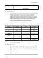
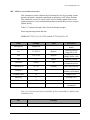
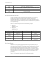
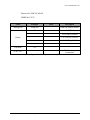
1
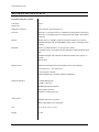
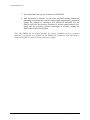
PMX04 PORTABLE 4-SLOT 3U PXI HYBRID INSTRUMENTATION SYSTEM USER’S MANUAL P/N: 82-0150-000 Released November 3rd, 2014 VTI Instruments Corp. 2031 Main Street Irvine, CA 92614-6509 (949) 955-1894 1 PMX04 Preface VTI Instruments Corp. Table of Contents Certification ................................................................................................................................ 5 Warranty ..................................................................................................................................... 5 Limitation of Warranty ............................................................................................................... 5 Restricted Rights Legend ............................................................................................................ 5 GENERAL SAFETY INSTRUCTIONS ................................................................................................. 6 Terms and Symbols..................................................................................................................... 6 Warnings ..................................................................................................................................... 6 Improper Use .............................................................................................................................. 7 Support Resources ........................................................................................................................ 8 Section 1 ......................................................................................................................................... 9 Introduction ................................................................................................................................... 9 Overview ..................................................................................................................................... 9 Unpacking ................................................................................................................................... 9 Section 2 ....................................................................................................................................... 11 Features ........................................................................................................................................ 11 Features ..................................................................................................................................... 11 Slot Configuration..................................................................................................................... 12 Detailed Specifications ................................................................................................................ 14 General Specifications .............................................................................................................. 14 Electrical ................................................................................................................................... 15 Operating Environment ............................................................................................................. 15 Random Vibration..................................................................................................................... 15 Related Products ....................................................................................................................... 15 Section 3 ....................................................................................................................................... 17 Preparation for Use..................................................................................................................... 17 Setting BIOS ............................................................................................................................. 17 Installing Operating System ...................................................................................................... 17 Installing the Operating System from USB Flash Disk ............................................................ 18 Installing the Operating System from USB CD-ROM ............................................................. 18 Installing Drivers ...................................................................................................................... 18 Main Chipset Driver ................................................................................................................. 19 Graphics Driver ......................................................................................................................... 19 Audio Driver ............................................................................................................................. 19 2 PMX04 Preface www.vtiinstruments.com Ethernet Driver.......................................................................................................................... 19 Ethernet Driver.......................................................................................................................... 19 Other Drivers ............................................................................................................................ 19 Section 4 ....................................................................................................................................... 21 Pre-Installed Application Software ........................................................................................... 21 Tablet System Control Software ............................................................................................... 21 Section 5 ....................................................................................................................................... 23 Installing PXI/PXIe Modules ..................................................................................................... 23 Section 6 ....................................................................................................................................... 25 GPS Function .............................................................................................................................. 25 Section 7 ....................................................................................................................................... 29 EMX-4x50 Discovery .................................................................................................................. 29 Section 8 ....................................................................................................................................... 35 Maintenance and Troubleshooting............................................................................................ 35 Items and Contents for Maintenance ........................................................................................ 36 Maintenance Period .................................................................................................................. 36 Precautions ................................................................................................................................ 37 Section 9 ....................................................................................................................................... 39 Transportation & Storage .......................................................................................................... 39 Transportation ........................................................................................................................... 39 Storage ...................................................................................................................................... 39 Section 10 ..................................................................................................................................... 41 GP5MX1513F1 GPS Receiver Module ..................................................................................... 41 About the Module ..................................................................................................................... 41 Features ..................................................................................................................................... 41 Applications .............................................................................................................................. 41 GPS Receiver Key Parameters.................................................................................................. 42 NMEA Output Message ............................................................................................................ 42 NMEA Protocol Frame ............................................................................................................. 42 NMEA Protocol Record ............................................................................................................ 43 Proprietary NMEA Input Message ........................................................................................... 43 Message Parameters .................................................................................................................. 43 Section 11 ..................................................................................................................................... 45 Appendix I: Details of NMEA Output Messages ..................................................................... 45 PMX04 Preface 3 VTI Instruments Corp. CGA-Global Positioning System Fixed Data ........................................................................... 45 Position Fix Indicators .............................................................................................................. 46 GLL - Geographic Position – Latitude/Longitude .................................................................... 46 GSA-GNSS DOP and Active Satellites .................................................................................... 46 GSV-GNSS Satellites in View.................................................................................................. 47 RMC – Recommended Minimum Specific GNSS Data ........................................................... 48 VTG – Course Over Ground and Ground Speed ...................................................................... 49 Section 12 ..................................................................................................................................... 51 Appendix II: Proprietary NMEA Input Message .................................................................... 51 100 – SetSerialPort ................................................................................................................... 51 101 – NavigationInitialization .................................................................................................. 52 102 – SetDGPSPort................................................................................................................... 53 103 – Query/Rate Control ......................................................................................................... 53 104 – LLANavigationInitialization........................................................................................... 55 105 – Development Data On/Off .............................................................................................. 56 106 – Select Datum ................................................................................................................... 56 TABLE OF FIGURES Figure 2-1: PMX04 Front View.................................................................................................... 11 Figure 2-2: PMX04 Rear View ..................................................................................................... 12 Figure 5-1: Acceptable PXI Modules ........................................................................................... 23 Figure 6-1: Driver Not Installed or Installed Incorrectly .............................................................. 25 Figure 6-2: Driver is Already Installed ......................................................................................... 26 Figure 6-3: System Control of PXI Pad ........................................................................................ 26 Figure 6-4: GPS Antenna Interface............................................................................................... 27 Figure 7-1: VTI PCIe System Software Package Setup Wizard................................................... 29 Figure 7-2: VTI PCIe System Software Package License Agreement ......................................... 30 Figure 7-3: Select Setup Type Selection ....................................................................................... 30 Figure 7-4: Installation Folder ...................................................................................................... 31 Figure 7-5: Begin Installation ....................................................................................................... 31 Figure 7-6: Select Device Manager .............................................................................................. 32 Figure 7-7: Confirm SentinelEX Under VTI PXIe Devices ......................................................... 32 Figure 7-8: Access the Soft Front Panel via Browser ................................................................... 33 Figure 8-1: Maintenance and Trouble Shooting ........................................................................... 36 Figure 10-1: GPS Receiver Parameters ........................................................................................ 42 Figure 12-1: Set Serial Port Data Format ..................................................................................... 51 Figure 12-10: Development Data On/Off Format ........................................................................ 57 4 PMX04 Preface www.vtiinstruments.com CERTIFICATION VTI Instruments Corp. (VTI) certifies that this product met its published specifications at the time of shipment from the factory. Note that the contents of this document are subject to change without notice. WARRANTY The product referred to herein is warranted against defects in material and workmanship for a period of one year from the receipt date of the product at customer’s facility. The sole and exclusive remedy for breach of any warranty concerning these goods shall be repair or replacement of defective parts, or a refund of the purchase price, to be determined at the option of VTI. Note that specifications are subject to change without notice. For warranty service or repair, this product must be returned to a VTI Instruments authorized service center. The product shall be shipped prepaid to VTI and VTI shall prepay all returns of the product to the buyer. However, the buyer shall pay all shipping charges, duties, and taxes for products returned to VTI from another country. VTI warrants that its software and firmware designated by VTI for use with a product will execute its programming when properly installed on that product. VTI does not however warrant that the operation of the product, or software, or firmware will be uninterrupted or error free. LIMITATION OF WARRANTY The warranty shall not apply to defects resulting from improper or inadequate maintenance by the buyer, buyersupplied products or interfacing, unauthorized modification or misuse, operation outside the environmental specifications for the product, or improper site preparation or maintenance. VTI Instruments Corp. shall not be liable for injury to property other than the goods themselves. Other than the limited warranty stated above, VTI Instruments Corp. makes no other warranties, express or implied, with respect to the quality of product beyond the description of the goods on the face of the contract. VTI specifically disclaims the implied warranties of merchantability and fitness for a particular purpose. RESTRICTED RIGHTS LEGEND Use, duplication, or disclosure by the Government is subject to restrictions as set forth in subdivision (b)(3)(ii) of the Rights in Technical Data and Computer Software clause in DFARS 252.227-7013. VTI Instruments Corp. 2031 Main Street Irvine, CA 92614-6509 U.S.A PMX04 Preface 5 VTI Instruments Corp. GENERAL SAFETY INSTRUCTIONS Review the following safety precautions to avoid bodily injury and/or damage to the These precautions must be observed during all phases of operation or service of this Failure to comply with these precautions, or with specific warnings elsewhere in this violates safety standards of design, manufacture, and intended use of the product. Note product contains no user serviceable parts or spare parts. product. product. manual, that this Service should only be performed by qualified personnel. Disconnect all power before servicing. TERMS AND SYMBOLS These terms may appear in this manual: WARNING Indicates that a procedure or condition may cause bodily injury or death. CAUTION Indicates that a procedure or condition could possibly cause damage to equipment or loss of data. These symbols may appear on the product or in the manual: ATTENTION - Important instructions Indicates hazardous voltage. Frame or chassis ground Indicates that the product was manufactured after August 13, 2005. This mark is placed in accordance with EN 50419, Marking of electrical and electronic equipment in accordance with Article 11(2) of Directive 2002/96/EC (WEEE). End-of-life product can be returned to VTI by obtaining an RMA number. Fees for take-back and recycling will apply if not prohibited by national law. WARNINGS Follow these precautions to avoid injury or damage to the product: 6 Use proper Power Cord To avoid hazard, only use the power cord specified for this product. Use proper Power Source To avoid electrical overload, electric shock, or fire hazard, do not use a power source that applies other than the specified voltage. The mains outlet that is used to power the equipment must be within 3 meters of the device and shall be easily accessible. PMX04 Preface www.vtiinstruments.com Use proper Power Source To avoid electrical overload, electric shock, or fire hazard, do not use a power source that applies other than the specified voltage. The mains outlet that is used to power the equipment must be within 3 meters of the device and shall be easily accessible. Use proper Fuse To avoid fire hazard, only use the type and rating fuse specified for this product. Power Consumption Prior to plugging-in PXI modules, it is imperative that the power consumption of all modules that will be installed in the mainframe be calculated for all power supply rails. The required information is available in detailed specifications of this chassis, and respective I/O card user manuals. Failure to do so may result in damaging the switch card and the mainframe. Avoid Electric Shock To avoid electric shock or fire hazard, do not operate this product with the covers removed. Do not connect or disconnect any cable, probes, test leads, etc. while they are connected to a voltage source. Remove all power and unplug unit before performing any service. Service should only be performed by qualified personnel. Ground the Product This product is grounded through the grounding conductor of the power cord. To avoid electric shock, the grounding conductor must be connected to earth ground. Operating Conditions To avoid injury, electric shock or fire hazard: - Do not operate in wet or damp conditions. - Do not operate in an explosive atmosphere. - Operate or store only in specified temperature range. - Provide proper clearance for product ventilation to prevent overheating. - When selecting the installation location, be certain that there is enough space around the power plug and the outlet so that they are readily accessible. Do not insert the power cord into an outlet where accessibility to the plug cord is poor. - All unused slots should be closed with the dummy filler panels to ensure a proper air circulation. This is critical to avoid overheating of the cards. - DO NOT operate if any damage to this product is suspected. Product should be inspected or serviced only by qualified personnel. IMPROPER USE The operator of this instrument is advised that if the equipment is used in a manner not specified in this manual, the protection provided by the equipment may be impaired. Conformity is checked by inspection. PMX04 Preface 7 VTI Instruments Corp. SUPPORT RESOURCES Support resources for this product are available on the Internet and at VTI Instruments customer support centers. VTI Instruments Corp. World Headquarters VTI Instruments Corp. 2031 Main Street Irvine, CA 92614-6509 Phone: (949) 955-1894 Fax: (949) 955-3041 VTI Instruments Cleveland Instrument Division 5425 Warner Road Suite 13 Valley View, OH 44125 Phone: (216) 447-8950 Fax: (216) 447-8951 VTI Instruments, Pvt. Ltd. Bangalore Instrument Division 75, Millers Road Bangalore – 560 001 Karnataka India Phone: +91 80 4040 7900 Fax: +91 80 4170 0200 Technical Support Phone: (949) 955-1894 Fax: (949) 955-3041 E-mail: [email protected] Visit http://www.vtiinstruments.com for worldwide support sites and service plan information 8 PMX04 Preface www.vtiinstruments.com SECTION 1 INTRODUCTION OVERVIEW The PMX04 is a new generation of innovative instrumental products from VTI Instruments Corporation. It integrates an embedded controller, PXI/PXIe hybrid slots, a multipoint capacitive touch screen, LCD, and a 256 GB internal hard drive. The compact design of the PMX04 offers users a brand-new experience in portable testing. UNPACKING Upon arrival, the shipping carton should be inspected for damage. If the carton or any of its contents are damaged please contact VTI Instruments immediately for a replacement. Do not dispose of the carton or any of its contents; VTI Instruments will not replace the damaged product if these materials are not returned. Please check that the following materials are in the carton. If any of these materials are missing please contact VTI Instruments immediately. • • • PMX04 Introduction PMX04 - Portable 4-Slot 3U PXI Express “Tablet” with Integrated Display User’s Manual Power Cord 9 VTI Instruments Corp. 10 PMX04 Introduction www.vtiinstruments.com SECTION 2 FEATURES FEATURES The PMX04 includes the following features: • • • • • • • Intel i7 dual-core processor 14-inch multipoint capacitive touch screen Windows 8 operating system Hybrid mixed PXI/PXIe slots Durable design for construction or industrial environments QM67 PCH Chipset equipped with 4GB DDR3 DRAM Internal 256GB HDD Drive standard with SATA 3.0 Interface 6 1 5 2 3 4 Figure 2-1: PMX04 Front View 1. 2. 3. 4. 5. 6. PMX04 Features Air Out/Fan Heatsink Power Button Stereo Speakers Handle Mic Touch Screen 11 VTI Instruments Corp. 8 9 1 7 2 6 3 4 5 Figure 2-2: PMX04 Rear View 1. 2. 3. 4. 5. 6. 7. 8. 9. SATA 3.0 Hard Disk Dual USB 2.0 Parts Dual Gigabit Ethernet Ports Metal Kickstand Reserved for Battery (Optional) 4x PXI-H Slots Headset Jack GPS Antenna HDMI SLOT CONFIGURATION The PMX04 is a 4-slot PXI Express mainframe with an embedded controller, and 4 peripheral slots capable of accepting PXI Express or PXI Hybrid plug-in modules. The PXI Express hybrid slot delivers connectivity to either an x4 PCI Express link or to the 32-bit, 33 MHz PCI bus on the backplane. This allows PXI Express hybrid-compatible, or 32-bit cPCI/PXI-1 modules (without J2 connector), to be used in this slot. The PXIe timing slot accepts either a PXI Express module or a PXI Express system timing controller for advanced timing and synchronization. The system controller slot has configurable 4x4, 2x8 and 1x8 links, which allows all PXIe controllers to be supported per spec. 12 PMX04 Features www.vtiinstruments.com Figure 2-3: Backplane Architecture PMX04 Features 13 VTI Instruments Corp. DETAILED SPECIFICATIONS GENERAL SPECIFICATIONS Total Slots 4 slots Module Size 3U Standards Compliance PXI-1 hardware specification Rev 2.2 Processor Intel Core i7-3517UE processor/1.7GHz/dual-core/Intel QM77 PCH Chipset Intel Core i7-3612QE processor/2.1GHz/quad-core/Intel QM77 PCH Chipset (optional) Memory Double data rate 3 (DDR3) synchronous dynamic random access memory Standard equipped 4GB/1333MHz/DDR3 memory sticks, with 4GB memory capacity Hard Disk SATA 3.0 standard interface, access speed up to 6GB/s Compatible with 2.5-inch SSD solid-state hard disk or HDD mechanical hard disk Standard equipped with 7200 rpm mechanical hard disk, with a capacity of 500GB Knock-down Display Screen Thin-film Transistor Liquid-crystal Display (TFT LCD) technology 14.9-inch (13.97”), 16:9 wide screen 1366x768 pixel resolution LED backlight design, automatic brightness adjustment Peripheral Interfaces 2 Gigabit Ethernet port 2 USB 2.0 interfaces HDMI high-definition interface GPS Antenna interfaces Standard 3.5 mm headset jack Audio devices Multiple built-in stereo speakers Built-in dual digital array microphone Size 16.5” W x 2.6” D x 11.2”H Weight 15 Lbs. 14 PMX04 Features www.vtiinstruments.com ELECTRICAL Power Supply AC/DC Power Adapter AC Input 100 to 240 V AC, input current 2 A Input Frequency 50 to 60 Hz DC Input 19 V DC Battery (Optional) Optional Lithium Ion Battery pack for up to 2 hours of back up capacity OPERATING ENVIRONMENT Max DC Power Output 150 W Operating Temperature 0 ° C to 50 ° C Storage Temperature -20 ° C to 70 ° C Operating Humidity 8% - 80%, 95% RH@30 ° C, <65% (0 ° C to 50 ° ° C), no condensation Storage Humidity 5% - 95%, <65% (0 ° C to 50 °), no condensation RANDOM VIBRATION Operating 5Hz – 500Hz, 2Grms, three-axis RELATED PRODUCTS PMX09 PMX04-AVI PMX04-VID CMX09 CMX18 PMX04 Features Portable 9 Slot PXI Express System Portable 9 Slot PXI Express System for Avionics Test Applications Portable 9 Slot PXI Express System for Video & Graphics Applications 9 Slot PXI Express Chassis 18 Slot PXI Express Chassis 15 VTI Instruments Corp. 16 PMX04 Features www.vtiinstruments.com SECTION 3 PREPARATION FOR USE The Windows 8 operating system has been installed in the PMX04 before leaving the factory. It is necessary to read this section carefully only when the self-contained operating system fails or when you are installing a new operating system. SETTING BIOS The Basic Input Output System (BIOS) is a program providing communication at the bottom layer between the processor and peripheral devices. The BIOS setup utility contains the operation menu used for enabling characteristics of the tablet device. To enter the BIOS setup screen, perform the following steps: 1. Insert USB keyboard device; 2. Reboot PXI smart tablet; 3. Once the standby screen appears press the <Delete> key to enter the BIOS setup screen. Note: Changing BIOS setup may cause unexpected behavior or create boot up problems. For satisfying the requirements of most customers, settings are optimized for PXI applications by default. Changing the BIOS setup should only be done by well-qualified personnel. INSTALLING OPERATING SYSTEM The PMX04 is delivered with a factory-installed operating system. The PMX04 can be optionally set as booting from a USB CD-ROM or USB flash disk. Specific settings are as follows: Reboot the device and enter the BIOS setup screen, then go to BootHard Drive BBS PrioritiesBoot Option #1 […] to select the device that you want to boot from with priority. After that, press <F10> to save the changes that you made and reboot the device. PMX04 Preparation for Use 17 VTI Instruments Corp. INSTALLING THE OPERATING SYSTEM FROM USB FLASH DISK To install operating system from USB flash disk, perform the following steps: 1. Make sure there is Windows PE system in the USB flash disk as the boot system; 2. Insert the USB flash disk within which the OS installation file is placed; 3. Insert a USB keyboard device; 4. Reboot the PMX04, press <Delete> to enter the BIOS setup screen; 5. Go to BootHard Drive BBS Priorities Boot Option #1 […] successively and select USB flash disk as the first boot device; 6. Press <F10> to save the change that you made, PMX04 will reboot automatically. 7. Log on the Windows PE system, open the OS installation package and select the .exe file to execute it. INSTALLING THE OPERATING SYSTEM FROM USB CD-ROM To install the operating system from a USB CD-ROM, perform the following steps: 1. Insert the USB CD-ROM drive and put the OS installation CD onto the CDROM drive; 2. Insert a USB keyboard device; 3. Reboot the PMX04, press <Delete> to enter the BIOS setup screen; 4. Go to BootHard Drive BBS PrioritiesBoot Option #1 […] successively and select USB CD-ROM as the first boot device; 5. Press <F10> to save the changes that you made, the PMX04 will reboot automatically. 6. Enter the system installation screen and execute OS installation. For more detailed information about OS, refer to related documents of the OS manufacturer. The following operating systems are recommended for and supported by the PMX04: • • Windows 8 Pro (32-bit/64-bit) Windows 7 Pro (32-bit/64-bit) INSTALLING DRIVERS After the operating system is installed, you need to install some necessary drivers to make the system run efficiently. You can find the necessary drivers in the included CD-ROM. Note: You may also contact VTI Instruments directly to receive supplemental files, device drivers, or application software. 18 PMX04 Preparation for Use www.vtiinstruments.com MAIN CHIPSET DRIVER The main chipset driver for the PMX04 is Intel CEQM77. Before installation, please make sure that the operating system has been installed properly. The main chipset driver is in the folder DRIVER\Chipset under the root directory of the supplied CD. Please select the proper driver for 32-bit or 64-bit operating system depending on the OS installed on your device. GRAPHICS DRIVER The PMX04 uses an Intel Graphics Media Accelerator 5.0 on the Intel CEQM77 chipset for video graphic display. Before installation, please ensure that the operating system has been installed properly. The VGA driver is in the folder DRIVER\Graphics under the root directory of the supplied CD. Please select the proper driver for 32-bit or 64-bit operating system depending on the OS installed on your device. AUDIO DRIVER The PMX04 device uses Hi-Fi audio part and IDT STAC9200 sound chip. It supports a built-in dual-track speaker, built-in digital mic, and headset. The audio driver is in the folder DRIVER\Audio under the root directory of the supplied CD. Please select the proper driver for 32-bit or 64-bit operating system depending on the OS installed on your device. ETHERNET DRIVER A 10/100/1000 Mbps Ethernet port is integrated on the main board of the PMX04 and uses an Intel Gigabit Ethernet Controller as the primary chip. The Ethernet card driver can be found in the folder DRIVER\Ethernet under the root directory of the supplied CD. Please select the proper driver for 32-bit or 64-bit operating system depending on the OS installed on your device. ETHERNET DRIVER A 10/100/1000 Mbps Ethernet port is integrated on the main board of the PMX04 and uses an Intel Gigabit Ethernet Controller as the primary chip. The Ethernet card driver can be found in the folder DRIVER\Ethernet under the root directory of the supplied CD. Please select the proper driver for 32-bit or 64-bit operating system depending on the OS installed on your device. OTHER DRIVERS If other drivers are needed, please contact VTI Instruments directly. PMX04 Preparation for Use 19 VTI Instruments Corp. 20 PMX04 Preparation for Use www.vtiinstruments.com SECTION 4 PRE-INSTALLED APPLICATION SOFTWARE The PMX04 can be pre-configured at the factory with several application specific modules. The PMX04-VID is configured with any two of the following video formats; NTSC, VGA, DVI, SMPTE*, RS-422*, and Gigabit Video*. Each of these formats will have dual channel capabilities for signal generation on one channel and capture on the other. The installed EX Video Software package provides the user with the ability of configuring the signal generation and doing advanced analysis of the video captured. All of the captured data can be stored on the local HDD. The PMX04-AVI is integrated with advanced MIL-STD-1553B and ARINC-429 protocol interface cards, including an easy to use Protocol Analyzer package from Alta Data. TABLET SYSTEM CONTROL SOFTWARE The PMX04 system control software has the functions of temperature monitoring, trigger routing settings, and fan control. For instruction about specific configuration, please refer to Instruction on Control Program of the PMX04 Instrument System. Four temperature sensors inside the PMX04 monitor temperature and can be set to alarm based on user defined threshold values. Trigger routing can route a trigger source to peripherals as a form of hardware handshaking. For example, you may pass a software trigger source to an external trigger terminal. This function allows for tight synchronization among multiple modules. A powerful system timer and trigger logic control function are incorporated inside the PMX04, with which routing among multiple trigger modes such as software trigger, external trigger, TTL trigger, differential trigger, star trigger, and others can be realized. Four fans are equipped at the PMX04 slots for dissipating heat. Through the fan control software, each fan can be controlled separately, including displaying current rotation speed, setting minimum speed, automatic speed regulation, and full-speed operation. PMX04 Pre-Installed Application Software 21 VTI Instruments Corp. 22 PMX04 Pre-Installed Application Software www.vtiinstruments.com SECTION 5 INSTALLING PXI/PXIE MODULES The PMX04 is equipped with four PXI/PXIe hybrid slots with standard PXI/PXIe bus interface support. PXI, CPCI, PXIe, CPCIe functional modules such as oscilloscopes, digital multimeters, arbitrary waveform generators, communication modules and RF microwave modules, from a variety of manufacturers are compatible with plug-and-play support. To install PXI/PXIe Modules, perform the following steps: 1. Turn off power to the PMX04 system; 2. Confirm that the module to be installed PXI-Hybrid or PXIe module. Commonly used modules are shown in the images below. Figure 5-1: Acceptable PXI Modules Note: This tablet device supports 32-bit bus modules only. Do not insert 64-bit modules into the PMX04. PMX04 Installing PXI/PXIe Modules 23 VTI Instruments Corp. 3. Insert the module into any one of the slots of the PMX04. 4. After the module is installed, you can select and insert modular instruments depending on requirements to quickly form a small comprehensive instrument system. For example, by inserting a VTI EMX-4350 and EMX-1434 the PMX04 will have the necessary functions to perform modal analysis tests. Quick and free switching between instruments is available, turning the PMX04 into an all-in-one solution. Note: The PMX04 has an isolated ground. If a source instrument such as a function generator is connected to a digitizer on the PMX04, the ground on each side must be connected together in order to see the clean source signal. 24 PMX04 Installing PXI/PXIe Modules www.vtiinstruments.com SECTION 6 GPS FUNCTION The PMX04 includes a GPS module which communicates with the motherboard through a synchronous serial interface. The GPS function can be accessed via the following steps: 1. Open Device Manager, and check whether the Ports(COM&LPT) includes CP2102 USB to UART Bridge controller. Note: If it appears as shown in Figure 6-1, the driver was not installed or was installed incorrectly. Figure 6-1: Driver Not Installed or Installed Incorrectly PMX04 GPS Function 25 VTI Instruments Corp. If so, please use the Driver CD-ROM/DRIVER/USB to RS232 to re-install the driver and check device manager again. If it appears as shown in Figure 6-2, it means the driver is already installed. Figure 6-2: Driver is Already Installed Attention: The COM port is a virtual port, which allows you to choose the COM port number, such as COM1 & COM2. 2. Open the System Control of PXI Pad. Choose the WirelessControl panel, as shown in Figure 6-3. The default status is OFF. Switch the GPS function to ON to begin using it. Figure 6-3: System Control of PXI Pad 26 PMX04 GPS Function www.vtiinstruments.com Note: System Control of PXI Pad is installed in the default path: C:/ProgramFiles/PI/xPad.exe 3. The PMX04 uses an external GPS antenna. The GPS antenna interface is shown in Figure 6-4. The antenna uses an MCX socket. Please select the corresponding antenna plug. Figure 6-4: GPS Antenna Interface 4. Open the GPS application software and choose the COM port number through the Device Manager. Other parameters are chosen as follows: 9600 bps, 8 data bits, no parity, 1 stop bits. The GPS module supports NMEA 0183 V3.0 protocol, which GGA, GLL, GSA, RMC, VTG are refreshed by 1Hz, and GSV by 0.2Hz. To get more information regarding the GPS data, please refer to the GP5MX1513F1 GPS Receiver Module Specification in section 10. PMX04 GPS Function 27 VTI Instruments Corp. 28 PMX04 GPS Function www.vtiinstruments.com SECTION 7 EMX-4X50 DISCOVERY In order to discover the VTI EMX-4x50 series card(s) with the VTI PMX04 on Windows 8, follow these steps: 1. Download and install the VTI PCIe System Software Package (VTI P/N: 720380-000) from www.vtiinstruments.com. Figure 7-1: VTI PCIe System Software Package Setup Wizard PMX04 EMX-4x50 Discovery 29 VTI Instruments Corp. Figure 7-2: VTI PCIe System Software Package License Agreement Figure 7-3: Select Setup Type Selection 30 PMX04 EMX-4x50 Discovery www.vtiinstruments.com Figure 7-4: Installation Folder Figure 7-5: Begin Installation PMX04 EMX-4x50 Discovery 31 VTI Instruments Corp. 2. After the installation is complete, right-click on the start button and select device manager. Figure 7-6: Select Device Manager 3. Check that “SentinelEX” shows up under VTI PXIe Devices. Figure 7-7: Confirm SentinelEX Under VTI PXIe Devices 32 PMX04 EMX-4x50 Discovery www.vtiinstruments.com 4. Open a browser such a Mozilla Firefox or Google Chrome and enter “127.0.0.1” to see the list of VTI Instrument EMX-4x50 card(s) plugged into the PMX04. Figure 7-8: Access the Soft Front Panel via Browser PMX04 EMX-4x50 Discovery 33 VTI Instruments Corp. 34 PMX04 EMX-4x50 Discovery www.vtiinstruments.com SECTION 8 MAINTENANCE AND TROUBLESHOOTING If unexpected failures occur while operating the PMX04, please refer to table 8-1 below for possible corrective actions. If the problem persists, please contact VTI technical support for assistance. No. 1 2 3 Problem Cause Action Wrong LVDS port setting in BIOS setup Reboot the PMX04 and enter BIOS setup screen, then select Configuration→Intergrated Video Configuration→Active Local Flat Panel [Integrated LVDS] and IGD-LVDS Color Depth[18 bit] successively. Too high resolution or refresh rate setting Adjust resolution to 1366×768 and refresh rate to 60Hz. Wrong LAN port setting in BIOS setup Reboot the PMX04 and enter BIOS setup screen, then select Configuration→LAN Configuration→Onboard LAN [Enabled] successively. Network cable damaged Replace network cable IP address setting incorrect Adjust to correct IP address according to the actual condition Wrong USB port setting in BIOS setup Reboot the PMX04 and enter BIOS setup screen, then select Configuration→USB Configuration→USB Port 0~7 [Enabled] successively. No display or abnormal display on LCD screen Network port unable to communicate normally USB port not recognized PMX04 Maintenance and Troubleshooting 35 VTI Instruments Corp. 4 5 6 7 Device will turn on upon power is connected. Wrong parameter setting in BIOS setup Reboot the PMX04 and enter BIOS setup screen, then select Configuration→Power Control Configuration→After Power Failure [Remain off] successively. System time unable to be saved, always restore factory time Lithium battery runs out Contact qualified technician for replacing BIOS battery. PCIe link not enabled in BIOS setup Reboot the PMX04 and enter BIOS setup screen, then select Configuration→PCIe Expansion Slot Configuration→PCI Express Port [Enabled] successively. Driver not installed Install the driver of the corresponding module correctly. Non-standard PXI-H or PXIe module is used. Only 32-bit, instead of 64-bit, PXI bus module and PXIe bus module are supported. The pins on the rear panel inside the tablet device are bent. Contact VTI for repair information. Module not recognized Module cannot be inserted into the corresponding slot successfully. Figure 8-1: Maintenance and Trouble Shooting ITEMS AND CONTENTS FOR MAINTENANCE • • Peripheral slots of the PMX04 are only applicable for 3U sized PXI-H/PXIe modules; None of the slots in the PMX04 support hot swapping. Be sure not to unplug or plug modules with the power on. MAINTENANCE PERIOD When the device will not be used for a long period of time, it should be powered on and checked every 6 months to prevent dry failure of components like the electrolytic capacitor. To do so, insert a functional PXI module into a slot. With power on, open up the module soft front panel and confirm that the instrument is operating as expected. 36 PMX04 Maintenance and Troubleshooting www.vtiinstruments.com PRECAUTIONS If any circuit failure occurs during the process of using the PMX04, do not repair on your own, instead, contact VTI Instruments for repair. PMX04 Maintenance and Troubleshooting 37 VTI Instruments Corp. 38 PMX04 Maintenance and Troubleshooting www.vtiinstruments.com SECTION 9 TRANSPORTATION AND STORAGE TRANSPORTATION • Transportation condition: Environment temperature: -20°C ~ +70°C Relative humidity: 10% ~ 90% • The device should be used and stored under the environment specified in chapter 1 of this user manual. Heavy pressure or violent vibration should be avoided during storage or transportation. The device should be handled with care to avoid mechanical damage caused by impact. STORAGE • • PMX04 Transportation and Storage 39 VTI Instruments Corp. 40 PMX04 Transportation and Storage www.vtiinstruments.com SECTION 10 GP5MX1513F1 GPS RECEIVER MODULE ABOUT THE MODULE The GP5MX1513F1 Module features a high sensitivity, low power, fast capturing satellite. The GPS module is powered by a Sony 800 SM chipset which provides greater sensitivity and performance. This module is capable of receiving GPS signals in environments such as canyons and dense forests. FEATURES • • • • • • • • • • Support for 64-channel GPS. Ultra low power consumption 45mW Ultra high sensitivity to -170dBm 1uA backup current Fast TTFF at low signal levels Capable of SBAS (WAAS, EGNOS, MSAS) 3 GPIO available Built-in LNA and SAW filter Small form factor – 15 x 13 x 2.4 mm SMD type with stamp holes; RoHS compliant APPLICATIONS • • • • • • Personal positioning and navigation Automotive navigation Marine navigation Geography measure Speed measure Logistics management PMX04 GP5MX1513F1 GPS Receiver Module 41 VTI Instruments Corp. GPS RECEIVER KEY PARAMETERS GP5MX1513F1 Key Parameters Chip Module Sony chipset 800SM Frequency L1 1575.42MHz, C/A code Channels 64 Update rate 1Hz Tracking -170dBm Sensitivity Capture -152dBm Hot start (Open Sky) < 1s Acquisition Time Hot start (Indoor) < 15s Cold Start (Open Sky) 32s (static) Autonomous < 2m (2D RMS) Position Accuracy SBAS < 1m (2D RMS) Max. Altitude < 18,000 m Max. Velocity < 1,800 km/h NMEA 0183 V3. 0 Protocol Support NMEA 0183 V3.0, 4800 bps, 8 data bits, no parity, 1 stop bits (default), 1Hz: GGA, GLL, GSA, RMC, VTG 0.2Hz: GSV (1Hz GSV at 9600bps) Figure 10-1: GPS Receiver Parameters NMEA OUTPUT MESSAGE GP5MX1513F1 supported NMEA format data output. NOTE: For more information on the NMEA Standard please refer to the NMEA0183 Standard For Interfacing Marine Electronic Devices. NMEA PROTOCOL FRAME $ <Address> {,<value>} *<checksum> <CR><LF> Figure 10-2: Protocol Frame 42 PMX04 GP5MX1513F1 GPS Receiver Module www.vtiinstruments.com NMEA PROTOCOL RECORD NMEA Record GGA Description GPS fix data GLL Geographic GSA GNSS DOP and active satellite GSV GNSS satellites in view RMC Recommended minimum specific GNSS data VTG Course over ground and ground speed GRS GNSS range residuals GST GNSS range residuals ZDA Time & Data TXT Text Transmission Figure 10-3: NMEA Protocol Record NOTE: The GP5MX1513F1 receiving module supports all NMEA data formats including: GGA, GLL, GSA, GSV, RMC, and VTG. For details about these data formats please refer to Appendix I. PROPRIETARY NMEA INPUT MESSAGE MESSAGE PARAMETERS Start Sequence Payload Checksum End Sequence $PSRF<MID> Data *CKSUM <CR><LF> Figure 10-4: Message Parameters • • • • Message Identifier consisting of three numeric characters. Input messages begin at MID 100. Message specific data. CKSUM is a two-hex character checksum as defined in the NMEA specification NMEA-0183 Standard for Interfacing Marine Electronic Devices. Use of checksums is required on all input messages. Each message is terminated using Carriage Return (CR) Line Feed (LF) which is \r\n which is hex 0D0A. Because \r\n are not printable ASCII characters, they are omitted from the example strings but must be sent to terminate the message and cause the receiver to process that input message. PMX04 GP5MX1513F1 GPS Receiver Module 43 VTI Instruments Corp. Note: All fields in all proprietary NMEA messages are required, none are optional. All NMEA message are comma delimited. Proprietary NMEA Input Messages Message MID1 Description Set SerialPort 100 Set PORT A parameters and protocol Navigation Initialization 101 SetDGPSPort 102 Query/Rate Control 103 LLANavigationInitialization 104 Development Data On/Off 105 Development Data messages On/Off Select Datum 106 Selection of datum to be used for coordinate transformations Parameters required for start using X/Y/Z2 Set PORT B parameters for DGPS input Query standard NMEA message and/or set output rate Parameters required for start using Lat/Lon/Alt3 Figure 10-5: NMEA Input Messages Table 10-5 – Proprietary NMEA Input Messages • MID: Message Identification • 101: Input coordinates must be WGS84 • 104: Input coordinates must be WGS84 Note: The details about Proprietary NMEA input messages can be found in the GP5MX1513F1 Appendix II. 44 PMX04 GP5MX1513F1 GPS Receiver Module www.vtiinstruments.com SECTION 11 GP5MX1513F1 APPENDIX I: DETAILS OF NMEA OUTPUT MESSAGES CGA-GLOBAL POSITIONING SYSTEM FIXED DATA Table 11-1 contains the values for the following example: $GPGGA,053740.000,2503.6319,N,12136.0099,E,1,08,1.1,63.8,M,15.2,M,0000* 64 Name Message ID UTC Time Latitude N/S indicator Longitude E/W Indicator Position Fix Indicator Satellites Used HDOP Example $GPGGA 53740 2503.6319 N 12136.01 E 1 08 1,1 Units MSL Altitude Units Geoid Separation Units Age of Diff. Corr. 63.8 M 15.2 M mters mters mters mters second Diff. Ref. Station ID Checksum <CR><LF> 0 *64 Description GGA protocol header Hhmmss.sss Ddmm.mmmm N=north or S=south Dddmm.mmmm E=east or W=west See Table I-1-2 Range 0 to 12 Horizontal Dilution of Precision Null fields when DGPS is not used End of message termination Figure 11-1: Global Positioning System Fixed Data PMX04 Details of NMEA Output Messages 45 VTI Instruments Corp. POSITION FIX INDICATORS Value 0 1 2 3 5 6 Description Fix not available or invalid GPS SPS Mode, fix valid Differential GPS, SPS Mode, fix valid Not Supported Dead Reckoning Mode, fix valid Figure 11-2: Position Fixed Indicators GLL - GEOGRAPHIC POSITION – LATITUDE/LONGITUDE Table 11-3 contains the values for the following example: $GPGLL,2503.6319,N,12136.0099,E,053740.000,A,A*52 Name Example Units Description Message ID $GPGLL GLL protocol header Latitude 2503.6319 Ddmm.mmmm N/S indicator N N=north or S=south Longitude 12136.01 Dddmm.mmmm E/W indicator E E=east or W=west UTC Time 53740 Hhmmss.sss Status A Mode A Checksum *52 A=data valid or V=data not valid A=autonomous, D=DGPS, E=DR End of message termination <CR><LF> Figure 11-3: Geographic Position – Latitude/Longitude GSA-GNSS DOP AND ACTIVE SATELLITES Table 11-4 contains the values for the following example: $GPGSA,A,3,24,07,17,11,28,08,20,04,,,,,2.0,1.1,1.7*35 Name Message ID Mode 1 Mode 2 ID of satellite used ID of satellite used 46 Example $GPGSA A 3 24 07 Description GSA protocol header See Table 11.d See Table 11.e Sv on Channel 1 Sv on Channel 2 PMX04 Details of NMEA Output Messages www.vtiinstruments.com ….. ID of satellite used PDOP HDOP ….. Sv on Channel 12 Position Dilution of Precision Horizontal Dilution of Precision Vertical Dilution of Precision 2 1.1 VDOP Checksum <CR><LF> 1.7 *35 End of message termination Figure 11-4: GNSS DOP And Active Satellite Examples Value M Description Manual – forced to operate in 2D or 3D mode Automatic – allowed to automatically switch 2D/3D A Figure 11-5 Value 1 2 3 Description Fix not available 2D 3D Figure 11-6 GSV-GNSS SATELLITES IN VIEW Table 11-7 contains the values for the following example: $GPGSV,3,1,12,28,81,285,42,24,67,302,46,31,54,354,,20,51,077,46*73 $GPGSV,3,2,12,17,41,328,45,07,32,315,45,04,31,250,40,11,25,046,41*75 $GPGSV,3,3,12,08,22,214,38,27,08,190,16,19,05,092,33,23,04,127,*7B Name Example Message ID $GPGSV GSV protocol header Total number of messages 3 Range 1 to 3 Message number 1 Range 1 to 3 Satellites in view 12 Satellite ID 28 PMX04 Details of NMEA Output Messages Units Description Channel 1 (Range 01 to 32) 47 VTI Instruments Corp. Elevation 81 degrees Azimuth 285 degrees SNR (C/No) 42 dB-Hz Satellite ID 20 Elevation 51 degrees Azimuth 77 degrees SNR (C/No) 46 dB-Hz Checksum *73 Channel 1 (range 00 to 90) Channel 1 (Range 000 to 359) Channel 1 (Range 00 to 99, null when not tracking) Channel 4 (Range 01 to 32) Channel 4 (Range 00 to 90) Channel 4 (Range 000 to 359) Channel 4 (Range 00 to 99, null when not tracking) End of message termination <CR> <LF> Figure 11-7: GNSS Satellites in View Examples RMC – RECOMMENDED MINIMUM SPECIFIC GNSS DATA Table 11-8 contains the values for the following example: $GPRMC,053740.000,A,2503.6319,N,12136.0099,E,2.69,79.65,100106,,,A*53 Name Example Message ID $GPRMC RMC protocol header UTC Time 53740 RMC protocol header Status A A=data valid or V=data not valid Latitude 2503.6319 Ddmm.mmmm N/S Indicator N N=north or S=south Longitude 12136.01 dddmm.mmmm E/W Indicator E E=east or W=west Speed over ground 2.69 knots 79.65 degrees Course over ground Date 48 100106 Units Description True Ddmmyy PMX04 Details of NMEA Output Messages www.vtiinstruments.com Magnetic variation degrees E=east or W=west (Not shown) A=autonomous, D=DGPS, E=DR Variation sense Mode A Checksum *53 End of message termination <CR> <LF> Figure 11-8: Recommended Minimum Specific GNSS Data Example VTG – COURSE OVER GROUND AND GROUND SPEED Table 11-9 contains the value for the following example: $GPVTG,79.65,T,,M,2.69,N,5.0,K,A*38 Name Example Message ID $GPVTG Course over ground 79.65 Reference T Course over ground Units Description VTG protocol header degrees Measured heading True Degrees Measured heading Reference M Magnetic Speed over ground 2.69 Units N Speed over ground 5.0 Units K Kilometer per hour Mode A A=autonomous, D=DGPS, E=DR Checksum *38 Knots Measured speed Knots Km/hr <CR> <LF> Measured speed End of message termination Figure 11-9: VTG Data Format Example PMX04 Details of NMEA Output Messages 49 VTI Instruments Corp. 50 PMX04 Details of NMEA Output Messages www.vtiinstruments.com SECTION 12 APPENDIX II: PROPRIETARY NMEA INPUT MESSAGE 100 – SETSERIALPORT This command message is used to set the protocol (Sony binary or NMEA) and/or the communication parameters (Baud, data bits, stop bits, and parity). Generally, this command is used to switch the module back to Sony binary protocol mode where a more extensive command message set is available. When a valid message is received, the parameters are stored in battery-backed SRAM and the Evaluation Receiver restarts using the saved parameters. Table 12-1 contains the input values for the following example: Switch to Sony binary protocol at 9600, 8, N, 1 $PSRF100,0,9600,8,1,0*0C Name Example Units Description PSRF100 protocol header 0=Sony binary, 1=NMEA 4800, 9600, 19200, 38400, 57600 Message ID $PSRF100 Protocol 0 Baud 9600 DataBits 8 8,71 StopBits 1 0, 1 Parity 0 0=None, 1=Odd, 2=Even Checksum *0C End of message termination <CR> <LF> Figure 12-1: Set Serial Port Data Format PMX04 Proprietary NMEA Input Message 51 VTI Instruments Corp. 101 – NAVIGATIONINITIALIZATION This command is used to initialize the Evaluation Receiver by providing current position (in X, Y, Z coordinates), clock offset, and time. This enables the Evaluation Receiver to search for the correct satellite signals at the correct signal parameters. Correct initialization parameters enable the Evaluation Receiver to acquire signals quickly. Table 12-2 contains the input values for the following example: Start using known position and time $PSRF101,-2686700,-4304200,3851624,96000,497260,921,12,3*1C Name Example Units Description PSRF101 protocol header Message ID $PSRF101 ECEF X -2686700 Meters X coordinate position ECEF Y -4304200 Meters Y coordinate position ECEF Z 3851624 Meters Z coordinate position ClkOffset 96000 Hz TimeOfWeek 497260 Seconds WeekNo 921 GPS Week Number ChannelCount 12 Range 1 to 12 ResetCfg 3 See table 12-3 Checksum *1C Clock Offset of the Evaluation Receiver GPS Time Of Week <CR> <LF> End of message termination Figure 12-2: Navigation Initialization Data Format Note: Use 0 for last saved value if available. If this is unavailable, a default value of 96000 is used. 52 Hex Example 0x01 Hot Start – All data valid 0x02 Warm Start – Ephemeris cleared 0x03 Warm Start (with Init) – Ephemeris cleared, initialization data loaded PMX04 Proprietary NMEA Input Message www.vtiinstruments.com 0x04 Cold Start – Clears all data in memory 0x08 Clear Memory – Clears all data in memory and resets the receiver back to factory defaults Figure 12-3: Reset Configuration 102 – SETDGPSPORT This command is used to control the serial port used to receive RTCM differential corrections. Differential receivers may output corrections using different communication parameters. If a DGPS receiver is used that has different communication parameters, use this command to allow the receiver to correctly decode the data. When a valid message is received, the parameters are stored in battery-backed SRAM and the receiver restarts using the saved parameters. Table 12-4 contains the input values for the following example: Set DGPS Port to be 9600,8,N,1. $PSRF102,9600,8,1,0*12 Name Example Units Description PSRF102 protocol header 4800, 9600, 19200, 38400 Message ID $PSRF102 Baud 9600 DataBits 8 8, 7 StopBits 1 0,1 Parity 0 0=None, 1=Odd, 2=Even Checksum *12 End of message termination <CR> <LF> Figure 12-4: Set GPS Port Data Format Note: RTCM is not supported. 103 – QUERY/RATE CONTROL This command is used to control the output of standard NMEA messages GGA, GLL, GSA, GSV, RMC, and VTG. Using this command message, standard NMEA messages may be polled once, or setup for periodic output. Checksums may also be enabled or disabled depending on the needs of the receiving program. NMEA message settings are saved in battery-backed memory for each entry when the message is accepted. PMX04 Proprietary NMEA Input Message 53 VTI Instruments Corp. Table 12-5 contains the input values for the following example: 1. Query the GGA message with checksum enabled $PSRF103,00,01,00,01*25 2. Enable VTG message for a 1 Hz constant output with checksum enabled $PSRF103,05,00,01,01*20 3. Disable VTG message $PSRF103,05,00,00,01*21 Name Example Units Message ID $PSRF103 Msg 0 See Table 12-6 Mode 1 0=SetRate, 1=Query Rate 0 CksumEnable 1 Checksum *25 Seconds Description PSRF103 protocl header Output – off=0, max=255 0=Disable Checksum, 1=Enable Checksum End of message termination <CR> <LF> Figure 12-5: Query/Rate Control Data Format Value Descriptions 0 GGA 1 GLL 2 GSA 3 GSV 4 RMC 5 VTG 6 MSS (If internal beacon is supported) 7 Not Defined 8 ZDA (if 1PPS output is supported) 9 Not Defined Figure 12-6 54 PMX04 Proprietary NMEA Input Message www.vtiinstruments.com 104 – LLANAVIGATIONINITIALIZATION This command is used to initialize the Evaluation Receiver by providing current position (in latitude, longitude, and altitude coordinates), clock offset, and time. This enables the receiver to search for the correct satellite signals at the correct signal parameters. Correct initialization parameters enable the receiver to acquire signals quickly. Table 12-7 contains the input values for the following example: Start using known position and time. $PSRF104,37.3875111,-121.97232,0,96000,237759,1946,12,1*07 Name Example Units Description PSRF104 protocol header Latitude position (range 90 to -90) Longitude position (Range 180 to -180) Message ID $PSRF104 Lat 37.387511 Degrees Lon -121.97232 Degrees Alt 0 Meters ClkOffset 96000 Hz TimeOfWeek 237759 Seconds WeekNo 1946 Extended GPS Week Number (1024 added) ChannelCount 12 Range 1 to 12 ResetCfg 1 See table 12-8 Checksum *07 Altitude position Clock Offset of the evaluation receiver GPS Time of Week <CR> <LF> End of message termination Figure 12-7: LLA Navigation Initialization Data Format Note: Use 0 for last saved value if available. If this is unavailable, a default value of 96000 is used. Hex Example 0x01 Hot Start – All data valid PMX04 Proprietary NMEA Input Message 55 VTI Instruments Corp. 0x02 Warm Start – Ephemeris cleared 0x03 Warm Start (with Init) – Ephemeris cleared, initialization data loaded 0x04 Cold Start – Clears all data in memory 0x08 Clear Memory – Clears all data in memory and resets the receiver back to factory defaults Figure 12-8 105 – DEVELOPMENT DATA ON/OFF Use this command to enable development data information if you are having trouble getting commands accepted. Invalid commands generate debug information that enables you to determine the source of the command rejection. Common reasons for input command rejection are invalid checksum or parameter out of specified range. Table 12-9 contains the input values for the following example: 1. Debug On $PSRF105,1*3E 2. Debug Off $PSRF105,0*3F Name Example Message ID $PSRF105 Debug 1 Checksum *3E Units Description PSRF105 protocol header 0=Off, 1=On End of message termination <CR><LF Figure 12-9: Development Data On/Off Data Format 106 – SELECT DATUM $PSGPS receivers perform initial position and velocity calculations using an earth-centered earth-fixed (ECEF) coordinate system. Results may be converted to an earth model (geoid) defined by the selected datum. The default datum is WGS 84 (World Geodetic System 1984) which provides a worldwide common grid system that may be translated into local coordinate systems or map datums. (Local map datums are a best fit to the local shape of the earth and not valid worldwide.) Table 12-10 Contains the input values for the following example: 56 PMX04 Proprietary NMEA Input Message www.vtiinstruments.com Datum select TOKYO_MEAN $PSRF106,178*32 Name Example Units Description Message ID $PSRF106 PSRF106 Protocol header 178 21=WGS84 178=TOKYO_MEAN Datum 179=TOKYO_JAPAN 180=TOKYO_KOREA 181=TOKYO_OKINAWA Checksum *32 End of message termination <CR> <LF> Figure 12-10: Development Data On/Off Format PMX04 Proprietary NMEA Input Message 57