1
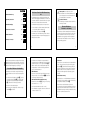
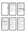
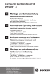
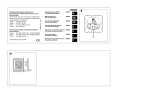
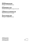
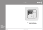
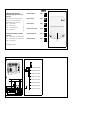
Bei Warenrücksendungen auf Grund von
Beanstandungen wenden Sie sich bitte an unser
Service Center:
Merten GmbH & Co. KG, Lösungen für intelligente
Gebäude, Service Center, Fritz-Kotz-Straße 8,
Industriegebiet Bomig-West, D-51674 Wiehl
Telefon: +49 2261 702-204
Telefax:
+49 2261 702-136
E-Mail:
[email protected]
Internet: www.merten.de
V5806-585-00 01/07
5806_585_00_Umschlag.fm Seite 1 Freitag, 26. Januar 2007 11:42 11
Bei technischen Fragen wenden Sie sich bitte an
unsere InfoLine:
Telefon: +49 1805 212581* oder +49 800 63783640
Telefax:
+49 1805 212582* oder +49 800 63783630
E-Mail:
[email protected]
Windsensorschnittstelle
580693
Wind sensor interface
580693
Windsensor-interface
580693
Interface para sensor de viento
580693
Interface du capteur de vent
580693
Windsensorschnittstelle
580693
*kostenpflichtig / fee required
5806_585_00_Umschlag.fm Seite 2 Freitag, 26. Januar 2007 11:42 11
„
$
0
L
N
- + 1 2
4
Sensor
0 => 10 Bft (~ 24,5 m/s = 88 km/h)
3
1
9 => 9 Bft (~ 20,8 m/s = 75 km/h)
8 => 8 Bft (~ 17,2 m/s = 62 km/h)
2
7 => 7 Bft (~ 14,1 m/s = 51 km/h)
§
L
AC 230 V
N
6 => 6 Bft (~ 11,0 m/s = 40 km/h)
5 => 5 Bft (~ 8,0 m/s = 29 km/h)
4 => 4 Bft (~ 5,5 m/s = 20 km/h)
L N
- +12
Motor
1
2N
L
M
3 => 3 Bft (~ 3,3 m/s = 12 km/h)
!
D
3
GB
NL
E
F
P
2
2
1
V5806-585-00.book Seite 1 Freitag, 26. Januar 2007 11:40 11
V5806-585-00.book Seite 2 Freitag, 26. Januar 2007 11:40 11
¼
Das können Sie mit der Windüberwachung
tun
D
Gebrauchsanweisung
2
Operating instructions
10
GB
Die Windüberwachung ermöglicht das Auffahren der
Jalousie in Abhängigkeit der Windstärke. Die Auf-Position schützt empfindliche Jalousielamellen und sorgt dadurch für Sicherheit bei aufkommendem Wind.
Gebruiksaanwijzing
18
NL
Die Windüberwachung besteht aus 2 Komponenten:
Instrucciones de servicio
29
E
Notice d'utilisation
34
F
Instruções de serviço
42
P
I
V5806-585-00.book Seite 4 Freitag, 26. Januar 2007 11:40 11
Zum Anschluß des Windsensors abgeschirmte Leitung
(Empfehlung JY-ST-Y 2x2x0,6) verwenden. Die Leitung
darf nicht gemeinsam mit 230 V-Leitungen verlegt werden (Gefahr der Einkopplung von Störungen).
Annschluss Windsensor-Schnittstelle
Die Windsensor-Schnittstelle ermöglicht die Ankopplung des Windsensors an den Jalousiesteuerungs-Einsatz.
1. Deckel des Anschlußgehäuses (Bild !1) nach Lösen beider Schrauben (Bild !2)‚ entfernen. (Bei
rückseitiger Leitungseinführung Gummitülle (Bild
„2) durchstoßen und Leitung einführen).
2. Gerät mit 2 Schrauben befestigen.
3. Leitungen ins Anschlußgehäuse einführen und gemäß Bild § anschließen.
4
V5806-585-00.book Seite 3 Freitag, 26. Januar 2007 11:40 11
Lebensgefahr durch elektrischen Strom.
Das Gerät darf nur von Elektrofachkräften montiert und angeschlossen werden. Beachten Sie
die länderspezifischen Vorschriften.
| Alle benötigten Schrauben und Dübel sind im LieInstallationshinweise
ferumfang enthalten.
Montage Windsensor,
Windsensor mit Heizung
• einem Windsensor (Art. Nr. 580692) oder Windsensor mit Heizung (Art. Nr. 580690) und
• der Windsensor-Schnittstelle (Bild !).
Der Windsensor wird in Verbindung mit dem Jalousiesteuerungs-Einsatz, bzw. mit den Binäreingängen des
KNX-Systemes betrieben.
Der Windsensor (Art. Nr. 580692) bzw der Windsensor
mit Heizung (Art. Nr. 580690) wird auf dem Dach oder
an der Hauswand montiert. Er muß an einer für die
Windstärkemessung günstigen Position angebracht
werden. Nicht im Windschatten montieren. Auf lagerichtige Anbringung achten.
2
3
V5806-585-00.book Seite 5 Freitag, 26. Januar 2007 11:40 11
Die Windsensor-Schnittstelle ist mit potentialfreien
Schließern bestückt. Zur Verwendung auf gleicher Phase Brücke zwischen L und K entsprechend Bild § installieren. Bei Anschluß von Niederspannungskreisen
am potentialfreien Schließer, Errichtungsbestimmungen nach VDE 0100 beachten.
Wahl Windsensor.
Es können 2 verschiedene Typen Windsensoren angeschlossen werden. Den Schalter (Bild „§) in die Position II bringen (Werkseinstellung).
Wahl Testbetrieb / Windstärkeauswertung
Mit dem Drehschalter (Bild „4) wird, je nach Stellung
der 10 Position (1, 2, 3, ... 9, 0):
• der Testbetrieb aktiviert (Position 1 und 2).
• die Windstärke vorgegeben, bei der die Jalousie auffährt oder (Position 3 - 0)
5
V5806-585-00.book Seite 6 Freitag, 26. Januar 2007 11:40 11
Testbetrieb
Die Positionen 1 oder 2 aktivieren den Testbetrieb: Nach
max. 1 Sekunde leuchtet die optische Anzeige (TestLED, Bild !3) auf. Wird das Geberrad gedreht, flackert die Test-LED in der Frequenz der Drehgeschwindigkeit und die Funktion des Gerätes kann schon bei
niedriger Umdrehungszahl des Geberrades geprüft
werden.
Windstärkeauswertung
Mit der Position 3 - 0 wird die Windstärke selektiert, bei
welcher die Jalousie aufgefahren wird. Die Einstellung
erfolgt in Beaufort (Bft), siehe Bild §.
Nach Verlassen des Testbetriebes vergehen ca.
4 Sekunden bis die eingestellte Windstärke vom Gerät
ausgewertet wird. Nach dem Wechsel zwischen zwei
Windstärkeeinstellungen wird die gewählte Einstellung
nach max. 4,5 Minuten übernommen.
6
V5806-585-00.book Seite 7 Freitag, 26. Januar 2007 11:40 11
V5806-585-00.book Seite 8 Freitag, 26. Januar 2007 11:40 11
| Windstärkeauswertungen zu realisieren, zu-
Um ein schnelles Umschalten zwischen zwei
Technische Daten
nächst Testbetrieb wählen und dann gewünschte
Windstärke einstellen.
Versorgungsspannung:
230 V AC, 50 Hz
Ausgang:
potentialfreier Kontakt zur
Ansteuerung eines
JalousiesteuerungsEinsatzes.
Ansprechzeit:
ca. 15 Sek.
(nach Überschreiten der
gewählten Windstärke)
Nachlaufzeit:
ca. 15 Min.
(nach Unterschreiten der
gewählten Windstärke)
Die Klemmen 1und 2 dienen als Verteilerklemmen und
sind geräteintern nicht beschaltet. Sie können z.B. für
einen Windsensor mit Heizung verwendet werden.
Die einzelne Verteilerklemme (Bild „1) dient zum Anschluß des Schutzleiters.
Deckel des Gerätes schließen.
7
V5806-585-00.book Seite 10 Freitag, 26. Januar 2007 11:40 11
What you can do with the wind monitoring
unit
The wind monitoring unit enables the blinds to be raised
or lowered depending on the wind strength. The Up
position protects fragile blind slats, thereby maintaining
safety in windy weather.
8
9
V5806-585-00.book Seite 11 Freitag, 26. Januar 2007 11:40 11
¼
Risk of fatal injury from electrical current.
The device may only be installed and connected
by skilled electricians. Observe the countryspecific regulations.
| The required screws and plugs are included with
• a wind sensor (art. no. 580692) or a wind sensor with
heating (art. no. 580690) and
• the wind sensor interface (Figure !).
10
V5806-585-00.book Seite 12 Freitag, 26. Januar 2007 11:40 11
Use a shielded wire for the wind sensor connection (we
suggest: JY-ST-Y 2x2x0.6). Do not lay the cable together
with 230 V wires (risk of interference).
Connecting the wind sensor interface
Installation notes
the delivery.
The wind monitoring unit consists of two components:
The wind sensor is operated in connection with the
blind control insert and the binary inputs of the KNX
system.
V5806-585-00.book Seite 9 Freitag, 26. Januar 2007 11:40 11
Installing the wind sensor,
wind sensor with heating
The wind sensor (art. no. 580692) or the wind sensor
with heating (art. no. 580690) is installed on the roof or
the outside wall of the building. It must be mounted in
a position suitable for measuring the wind strength. The
device must therefore not be mounted in the slipstream
of any objects. Ensure that the device is mounted in the
correct position.
11
The wind sensor is connected to the blind control insert
using the wind sensor interface.
1. Remove the lid of the connection housing (Figure
!1) by removing the two screws (Figure !2). (If
the cable entry is at the back, pierce through the
rubber grommet (Figure „2) and insert the wire).
2. Secure the device using two screws.
3. Insert cables into the connection housing and
connect them as shown in Figure §.
The wind sensor interface is equipped with floating
make contacts. For use at the same phase, install a
bridge between L and K as per Figure §. When low12
V5806-585-00.book Seite 13 Freitag, 26. Januar 2007 11:40 11
voltage circuits are connected to the floating make
contact, observe the VDE 0100 regulations.
V5806-585-00.book Seite 14 Freitag, 26. Januar 2007 11:40 11
Test mode
Selecting the wind sensor
Two different types of wind sensors can be connected.
Set the switch (Figure „§) to position II (factory
setting).
Selecting test mode / wind strength evaluation
Moving the rotary switch (Figure „4) into one of the
ten positions (1, 2, 3, ... 9, 0):
• activates the test mode (positions 1 and 2).
• defines the wind strength at which the blinds are
raised (position 3 - 0).
V5806-585-00.book Seite 15 Freitag, 26. Januar 2007 11:40 11
| strength evaluation to another, select the test
In order to quickly switch over from one wind
Positions 1 and 2 activate the test mode: The optical
display (test LED, Figure !3) lights up after a
maximum of one second. If the rotary sensor is rotated,
the test LED flickers at the frequency of the rotational
speed and one can test that the unit is working even
when the rotational speed of the rotary sensor is low.
Wind strength evaluation
Position 3 - 0 defines the wind strength at which the
blinds are raised. The setting is made in Beaufort (Bft)
units, see Figure §.
mode and then set the desired wind strength.
Terminals 1 and 2 serve as distributor terminals and are
not wired inside the unit. They can be used for a wind
sensor with heating, for example.
The individual distributor terminal (Figure „1) is used
to connect the protective conductor.
Close the lid of the unit.
After exiting the test mode, it takes the unit about
4 seconds for the device to evaluate the set wind force.
The selected setting will be applied after a maximum of
4.5 minutes after switching from one wind strength to
another.
13
V5806-585-00.book Seite 16 Freitag, 26. Januar 2007 11:40 11
14
15
V5806-585-00.book Seite 17 Freitag, 26. Januar 2007 11:40 11
V5806-585-00.book Seite 18 Freitag, 26. Januar 2007 11:40 11
Technical data
Mogelijkheden van de windbewaking
Supply voltage:
230 V AC, 50 Hz
Output:
Floating contact for the
control of a
blind control
insert.
Response time:
About 15 seconds
(after exceeding the
selected wind strength)
De windbewaking bestaat uit twee componenten:
About 15 minutes
(after exceeding the
selected wind strength)
• de windsensor-interface (afbeelding !).
Overshoot time:
16
De windbewaking maakt het mogelijk de jaloezie
omhoog te laten gaan afhankelijk van de windsterkte.
De omhoog-positie beschermt gevoelige
jaloezielamellen en zorgt hierdoor voor veiligheid bij
opkomende wind.
• een windsensor (art.nr. 580692) of windsensor met
verwarming (art.nr. 580690) en
De windsensor wordt in combinatie met de jaloeziebesturingssokkel, resp. met de binaire ingangen van het
KNX-systeem gebruikt.
17
18
V5806-585-00.book Seite 19 Freitag, 26. Januar 2007 11:40 11
¼
Levensgevaar door elektrische stroom.
Het apparaat mag uitsluitend door elektriciens
gemonteerd en aangesloten worden. Neem de
nationale voorschriften in acht.
V5806-585-00.book Seite 20 Freitag, 26. Januar 2007 11:40 11
Voor aansluiting van de windsensor een afgeschermde
leiding (aanbeveling JY-ST-Y 2x2x0,6) gebruiken. De
leiding mag niet samen met 230 V-leidingen gelegd
worden (gevaar voor koppeling van storingen).
| Alle benodigde schroeven en pluggen worden
Aanwijzingen voor de installatie
Aansluiting windsensor-interface
De windsensor-interface maakt de koppeling van de
windsensor aan de jaloezie-besturingssokkel mogelijk.
standaard meegeleverd.
Montage windsensor,
windsensor met verwarming
De windsensor (art.nr. 580692) resp. de windsensor
met verwarming (art.nr. 580690) wordt op het dak of
aan de huisgevel gemonteerd. De sensor moet op een
voor de meting van de windkracht gunstige plaats
worden aangebracht. Niet in de luwte monteren. Zorg
ervoor dat het apparaat in de juiste positie wordt
aangebracht.
19
V5806-585-00.book Seite 22 Freitag, 26. Januar 2007 11:40 11
Testmodus
Positie 1 of 2 activeert de testmodus: na max. 1
seconde gaat de optische indicatie (test-LED,
afbeelding !3) branden. Als het sensorwiel wordt
gedraaid, knippert de test-LED met de frequentie van
de draaisnelheid en de functie van het apparaat kan al
bij een lage omwentelingssnelheid van het sensorwiel
worden gecontroleerd.
Windsterkte-analyse
Met de positie 3 - 0 wordt de windsterkte geselecteerd,
waarbij de jaloezie omhoog wordt bewogen. De
instelling vindt plaats in Beaufort (Bft), zie afbeelding
§.
1. Deksel van de aansluitbehuizing (afbeelding !1) na
het losdraaien van beide schroeven (afbeelding
!2) verwijderen. (bij kabelinvoer aan de achterzijde
de rubbertule (afbeelding „2) doordrukken en
leiding invoeren).
2. Apparaat met 2 schroeven bevestigen.
V5806-585-00.book Seite 21 Freitag, 26. Januar 2007 11:40 11
De windsensor-interface is uitgerust met potentiaalvrije
maakcontacten. Voor gebruik met dezelfde fase brug
tussen L en K volgens afbeelding § installeren. Bij
aansluiting van laagspanningscircuits op het
potentiaalvrije maakcontact, bepalingen conform VDE
0100 in acht nemen.
Selecteer windsensor.
Er kunnen 2 verschillende types windsensoren worden
aangesloten. Breng de schakelaar (afbeelding „§) in
positie II (fabrieksinstelling).
Selecteer testmodus / windsterkte-analyse
Met de draaischakelaar (afbeelding „4) wordt
afhankelijk van de stand (1, 2, 3, ... 9, 0):
• de testmodus geactiveerd (positie 1 en 2).
3. Leidingen in de aansluitbehuizing voeren en volgens
afbeelding § aansluiten.
• de windsterkte aangegeven, waarbij de jaloezie
omhoog beweegt (positie 3 - 0)
20
21
V5806-585-00.book Seite 23 Freitag, 26. Januar 2007 11:40 11
V5806-585-00.book Seite 24 Freitag, 26. Januar 2007 11:40 11
windsterkte-instellingen wordt de geselecteerde
instelling na max. 4,5 minuten overgenomen.
Technische gegevens
Voedingsspanning:
230 V AC, 50 Hz
Uitgang:
De klemmen 1 en 2 zijn bedoeld als verdeelklemmen en
zijn apparaat-intern niet geschakeld. Ze kunnen bijv.
voor een windsensor met verwarming worden gebruikt.
potentiaalvrij contact voor
aansturing van een
jaloezie-besturingssokkel.
Aanspreektijd:
De afzonderlijke verdeelklem (afbeelding „1) is
bedoeld voor aansluiting van de aardedraad.
ca. 15 sec.
(na overschrijding van de
geselecteerde windsterkte)
Nalooptijd:
ca. 15 min.
(na overschrijding van de
geselecteerde windsterkte)
| windsterkte-analyses te realiseren, dient u eerst
Om een snelle omschakeling tussen twee
de testmodus te selecteren en daarna de
gewenste windsterkte in te stellen.
Deksel van het apparaat sluiten.
Na het verlaten van de testmodus gaan ca. 4 seconden
voorbij tot de ingestelde windsterkte door het apparaat
wordt geanalyseerd. Na het wisselen tussen twee
22
23
24
V5806-585-00.book Seite 25 Freitag, 26. Januar 2007 11:40 11
V5806-585-00.book Seite 26 Freitag, 26. Januar 2007 11:40 11
Utilidad de la vigilancia eólica
La vigilancia eólica permite subir la persiana de lamas
en función de la fuerza del viento. La posición de
encendido protege las delicadas lamas de la persiana y
ofrece seguridad en caso de que se levante un viento
fuerte.
V5806-585-00.book Seite 27 Freitag, 26. Januar 2007 11:40 11
¼
Peligro de muerte por descarga eléctrica.
El dispositivo sólo debe ser montado y conectado
por electricistas debidamente cualificados. Tenga
en cuenta la normativa específica del país.
| Todos los tornillos y tacos necesarios para la
Indicaciones para la instalación
instalación están incluidos en el suministro.
La vigilancia eólica consta de 2 componentes:
Montaje del sensor de viento
Sensor de viento con calefacción
• un sensor de viento (ref. 580692) o un sensor de
viento con calefacción (ref. 580690) y
• una interface para sensor de viento (figura !).
El sensor de viento (ref. 580692) o el sensor de viento
con calefacción (ref. 580690) se monta en el techo o en
una pared, debiendo colocarse en una posición en la
que pueda medir la fuerza del viento. No lo monte a
resguardo del viento. Es importante colocarlo en el
lugar correcto.
El sensor de viento funciona en combinación con el
control de persianas de lamas o con las entradas
binarias del sistema KNX.
25
V5806-585-00.book Seite 28 Freitag, 26. Januar 2007 11:40 11
Para conectar el sensor de viento, utilice un cable
apantallado (sugerencia: JY-ST-Y 2x2x0,6). El cable no
debe instalarse con cables de 230 V (peligro de
acoplamiento de interferencias).
Conexión de la interface para sensor de
viento
La interface para sensor de viento permite acoplar el
sensor de viento al control de persianas de lamas.
1. Retire la tapa de la caja de unión (figura !1)
aflojando los dos tornillos (figura !2). (En el caso
de que el cable tenga la entrada por la parte trasera,
perfore el revestimiento de goma (figura „2) e
introduzca el cable).
2. Fije el aparato con dos tornillos.
3. Introduzca los cables en la caja de unión y conéctelos
como se indica en la figura §.
28
26
27
V5806-585-00.book Seite 29 Freitag, 26. Januar 2007 11:40 11
La interface para sensor de viento está dotada de
contactos n.a. libres de potencial. Para su empleo en la
misma fase, instale un puente entre L y K como se
ilustra en la figura §. Para conectar circuitos de baja
tensión a los contactos n.a. libres de potencial, tenga en
cuenta las normas VDE 0100.
Elección del sensor de viento.
Se pueden conectar 2 tipos diferentes de sensores de
viento. Coloque el interruptor (figura „§) en la
posición II (ajuste de fábrica).
Elección del modo de test / evaluación de la fuerza
del viento
En función de la posición seleccionada (1, 2, 3, ... 9, 0),
el conmutador (figura „4) permite:
• activar el modo de test (posición 1 y 2)
• especificar la fuerza del viento necesaria para que la
persiana de lamas suba (posición 3 0)
29
V5806-585-00.book Seite 30 Freitag, 26. Januar 2007 11:40 11
Modo de test
Las posiciones 1 y 2 activan el modo de test: El
indicador óptico (LED de prueba, figura !3) se
ilumina transcurrido un segundo como máximo. Al girar
la rueda, el LED de prueba parpadea en la frecuencia de
la velocidad a la que se gira el botón. El funcionamiento
del aparato se puede comprobar incluso si la velocidad
de giro de la rueda es baja.
Evaluación de la fuerza del viento
Las posiciones 3 - 0 permiten seleccionar la fuerza del
viento necesaria para que la persiana de lamas suba. El
ajuste se realiza en la escala de medida Beaufort (Bft),
véase la figura §.
Una vez que se ha salido del modo de test, transcurren
aprox. 4 segundos hasta que el aparato evalúa la
intensidad del viento seleccionada. Al cambiar entre
dos ajustes de fuerza del viento, el nuevo ajuste
30
V5806-585-00.book Seite 31 Freitag, 26. Januar 2007 11:40 11
V5806-585-00.book Seite 32 Freitag, 26. Januar 2007 11:40 11
seleccionado se aplica transcurrido un máx. de 4,5
minutos.
V5806-585-00.book Seite 33 Freitag, 26. Januar 2007 11:40 11
Datos técnicos
| evaluaciones de la intensidad del viento,
Para cambiar de forma rápida entre dos
seleccione primero el modo de test y, a
continuación, ajuste la fuerza del viento que
desee.
Los bornes 1 y 2 hacen las veces de distribuidores y no
están conectados en el interior del aparato. Pueden
utilizarse, por ejemplo, para un sensor de viento con
calefacción.
Tensión de alimentación:
230 V CA, 50 Hz
Salida:
contacto libre de potencial
para control de
persianas de lamas.
Tiempo de respuesta:
aprox. 15 seg.
(una vez superada la
fuerza del viento
seleccionada)
Tiempo de encendido:
aprox. 15 min.
(durante los cuales no se ha
superado la fuerza del
viento seleccionada)
El borne de distribución individual (figura „1) sirve
para conectar el conductor de tierra.
Cierre la tapa del aparato.
31
V5806-585-00.book Seite 34 Freitag, 26. Januar 2007 11:40 11
Voici les possibilités qu'offre la surveillance
du vent
La surveillance du vent permet de remonter le store en
fonction de la force du vent. La position « Montée »
protège les lamelles sensibles du store et offre ainsi
toute la sécurité requise en cas de vent forcissant.
Le dispositif de surveillance du vent est constitué de 2
composants :
• un capteur de vent (réf. 580692) ou un capteur de
vent avec chauffage (réf. 580690) et
• une interface pour capteur de vent (figure !).
Le capteur de vent est exploité avec un mécanisme de
commande de stores ou avec les entrées binaires du
système KNX.
32
33
V5806-585-00.book Seite 35 Freitag, 26. Januar 2007 11:40 11
¼
Danger de mort dû au courant électrique.
Seuls des électriciens sont autorisés à monter et
à raccorder l'appareil. Respectez les prescriptions
nationales.
| Toutes les vis et chevilles nécessaires sont
Remarques relatives à l'installation
V5806-585-00.book Seite 36 Freitag, 26. Januar 2007 11:40 11
Utilisez, pour le raccordement du capteur de vent, un
câble blindé (recommandation JY-ST-Y 2x2x0,6). Le
câble ne doit pas être posé ensemble avec des câbles
230 V (danger de perturbations).
Raccordement de l'interface pour capteur de
vent
comprises dans la fourniture.
L'interface pour capteur de vent permet l'accouplement
du capteur de vent au mécanisme de commande de
stores.
Montage du capteur de vent,
capteur de vent à chauffage
Le capteur de vent (réf. 580692) ou le capteur de vent
avec chauffage (580690) se monte soit sur le toit soit au
mur. Il est important de choisir un endroit favorable pour
mesurer la force du vent. Ne pas monter l'appareil dans
un endroit abrité du vent. Veillez à installer l'appareil
dans une position correcte.
n :1.Retirez le couvercle du boîtier de connexion (figure
!1) après avoir desserré les deux vis (figure
!2). (si le câble est introduit par l'arrière, perforez
le passe-fil en caoutchouc (figure „2) et insérez le
câble.
n :2.Fixez l'appareil à l'aide de 2 vis.
n :3.Insérez les câbles dans le boîtier de raccordement
et connectez-les conformément à la figure §.
34
35
36
V5806-585-00.book Seite 37 Freitag, 26. Januar 2007 11:40 11
L'interface du capteur de vent est équipée d'un contact
NO libre de potentiel. Pour une utilisation sur une
même phase, installez un pont entre L et K
conformément à la figure §. Pour le raccordement de
circuits basse tension à un contact libre de potentiel,
respectez les règles d'installation selon VDE 0100.
Sélection capteur de vent
Il est possible de raccorder 2 types de capteurs de vent
différents. Mettez l'interrupteur (figure „§) en
position II (valeurs par défaut).
Sélection mode test/évaluation de la force du vent
Au moyen du commutateur rotatif (figure „4), il est
possible, en fonction de la position (1, 2, 3, ... 9, 0),
• d'activer le mode test (position 1 et 2) ou
• de définir la force du vent à partir de laquelle le store
remonte (position 3 - 0).
37
V5806-585-00.book Seite 40 Freitag, 26. Januar 2007 11:40 11
V5806-585-00.book Seite 38 Freitag, 26. Januar 2007 11:40 11
Mode test
V5806-585-00.book Seite 39 Freitag, 26. Januar 2007 11:40 11
| deux sélections de forces de vent, il est
Afin de permettre la commutation rapide entre
Les positions 1 et 2 activent le mode test : après max.
1 seconde, l'indicateur optique (LED Test, figure !3)
s'allume. Si la roue du transmetteur tourne, la LED de
test clignote en fonction de la vitesse de rotation,
permettant ainsi de vérifier le bon fonctionnement de
l'appareil même sous un faible nombre de tours.
Évaluation de la force du vent
Les positions 3 - 0 permettent de sélectionner la force
du vent déclenchant la remontée du store. Le réglage
s'effectue selon l'échelle Beaufort (Bft), voir figure §.
Une fois le mode test quitté, 4 secondes s'écoulent
avant que la force du vent réglée puisse être interprétée
par l'appareil. Après la sélection de deux valeurs de
force de vent, le réglage sélectionné est repris après
4,5 minutes au maximum.
préférable de sélectionner d'abord le mode test
et de régler ensuite les forces de vent
souhaitées.
Les bornes 1 et 2 servent de bornes de distribution et
ne sont pas câblées à l'intérieur de l'appareil. Elles
peuvent être utilisées par exemple pour un capteur de
vent avec chauffage.
La borne de distribution séparée (figure „1) sert au
raccordement du conducteur de protection.
Fermez le couvercle de l'appareil.
38
39
V5806-585-00.book Seite 41 Freitag, 26. Januar 2007 11:40 11
Caractéristiques techniques
V5806-585-00.book Seite 42 Freitag, 26. Januar 2007 11:40 11
O que pode fazer com a monitorização do
vento
Tension d'alimentation
230 V CA, 50 Hz
Sortie
contact libre de potentiel
pour l'activation d'un
mécanisme de commande
de stores.
A monitorização do vento permite a subida do estore
em função da força do vento. A posição em cima
protege as lamelas sensíveis do estore, garantindo a
segurança em caso de vento.
Temps de réponse :
env. 15 s
(après dépassement positif
de la force de vent
sélectionnée)
A monitorização do vento é composta por 2
componentes:
env. 15 min
(après dépassement égatif
de la force de vent
sélectionnée)
• a interface para anemómetro (figura !).
Durée d'allumage :
40
• um anemómetro (art. n.º 580692) ou anemómetro
com aquecimento (art. n.º 580690) e
O anemómetro é utilizado em combinação com o
mecanismo de comando de estores ou com as
entradas binárias do sistema KNX.
41
42
V5806-585-00.book Seite 43 Freitag, 26. Januar 2007 11:40 11
¼
Perigo de morte devido a corrente eléctrica.
O aparelho só pode ser instalado e ligado por
técnicos especializados. Observe as normas
específicas do país.
V5806-585-00.book Seite 44 Freitag, 26. Januar 2007 11:40 11
Para ligação do anemómetro deve utilizar um cabo
blindado (recomendamos JY-ST-Y 2x2x0,6). O cabo não
deve ser instalado junto com cabos de 230 V (existe o
perigo de acoplamento de interferências).
| Todos os parafusos e buchas necessários estão
Instruções de instalação
Montagem do anemómetro,
Anemómetro com aquecimento
O anemómetro (art. n.º 580692) ou anemómetro com
aquecimento (art. n.º 580690) é montado no telhado ou
na parede da casa. O aparelho tem de ser colocado
numa posição favorável para a medição da força do
vento. Não monte o aparelho ao abrigo do vento.
Respeite o posicionamento correcto.
43
V5806-585-00.book Seite 46 Freitag, 26. Januar 2007 11:40 11
Selecção do funcionamento de teste / avaliação da
força do vento.
Com o interruptor rotativo (figura „4) é possível, em
função das 10 posições (1, 2, 3, ... 9, 0):
• Activar o funcionamento de teste (posição 1 e 2).
• Predeterminar a força do vento a que o estore deve
ser subido (posição 3 - 0).
Funcionamento de teste
As posições 1 ou 2 activam o funcionamento de teste:
após 1 segundo, no máximo, o indicador óptico acendese (LED de teste, figura !3). Quando a roda sensora
é rodada, o LED de teste cintila com a mesma
frequência da velocidade de rotação, sendo possível
verificar o funcionamento do dispositivo mesmo a baixa
rotação da roda sensora.
46
Ligação da interface para anemómetro
A interface para anemómetro permite acoplar o
anemómetro ao mecanismo de comando de estores.
incluídos no âmbito de fornecimento.
1. Remova a tampa da caixa de ligação (figura !1)
depois de desenroscar ambos os parafusos (figura
!2). (No caso de a entrada de cabos estar
localizada na parte de trás, perfure a bucha de
borracha (figura „2) e introduza o cabo).
V5806-585-00.book Seite 45 Freitag, 26. Januar 2007 11:40 11
A interface para anemómetro está equipada com
contactos de fecho livre de potencial. Para usar na
mesma fase, instale uma ponte entre L e K, em
conformidade com a figura §. No caso de ligação de
circuitos de baixa tensão a contactos de fecho livre de
potencial, observe as condições de constituição
segundo VDE 0100.
Selecção do anemómetro.
É possível a ligação de 2 tipos diferentes de
anemómetro. Coloque o interruptor (figura „§) na
posição II (ajuste de fábrica).
2. Fixe o aparelho com 2 parafusos.
3. Introduza os cabos na caixa de ligação e ligue-os em
conformidade com a figura §.
44
45
V5806-585-00.book Seite 47 Freitag, 26. Januar 2007 11:40 11
Avaliação da força do vento
Com a posição 3 - 0 é seleccionada a força do vento à
qual o estore é subido. O ajuste é feito em (Bft), ver
figura §.
Depois de se sair do funcionamento de teste, decorrem
cerca de 4 segundos até a força do vento ajustada ser
avaliada pelo aparelho. Após a comutação entre dois
ajustes da força do vento, o ajuste seleccionado é
assumido após 4,5 minutos, no máximo.
V5806-585-00.book Seite 48 Freitag, 26. Januar 2007 11:40 11
Os bornes 1 e 2 funcionam como bornes de distribuição
e não estão ligados ao circuito no interior do aparelho.
Podem ser usados, por ex., para um anemómetro com
aquecimento.
O borne de distribuição individual (figura „1) serve
para ligação do condutor de protecção.
Feche a tampa do dispositivo.
| da força do vento, seleccione primeiro o
Para comutar rapidamente entre duas avaliações
funcionamento de teste e depois ajuste a força
do vento desejada.
47
48
V5806-585-00.book Seite 49 Freitag, 26. Januar 2007 11:40 11
Dados técnicos
Tensão de alimentação:
230 V AC, 50 Hz
Saída:
Contacto livre de potencial
paracontrolo de um
mecanismo de comando
de estores.
Tempo de disparo:
aprox. 15 seg.
(depois de ultrapassada
a força do vento
seleccionada)
Tempo de continuação:
aprox. 15 min..
(depois da descida abaixo
da força do vento
seleccionada)
49