1
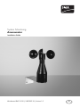
System Monitoring
Anemometer
Installation Guide
Windsensor-IEN101010 | 98-0025210 | Version 1.0
EN
SMA Solar Technology AG
Table of Contents
Table of Contents
1
1.1
1.2
1.3
Notes on this Guide . . . . . . . . . . . . . . . . . . . . . . . . . . . . . . .
Validity . . . . . . . . . . . . . . . . . . . . . . . . . . . . . . . . . . . . . . . . . . . .
Target Group . . . . . . . . . . . . . . . . . . . . . . . . . . . . . . . . . . . . . . .
Symbols Used . . . . . . . . . . . . . . . . . . . . . . . . . . . . . . . . . . . . . . .
2
2.1
2.2
Safety . . . . . . . . . . . . . . . . . . . . . . . . . . . . . . . . . . . . . . . . . . 5
Appropriate Usage . . . . . . . . . . . . . . . . . . . . . . . . . . . . . . . . . . . 5
Safety Precautions. . . . . . . . . . . . . . . . . . . . . . . . . . . . . . . . . . . . 5
3
3.1
3.2
3.3
Unpacking. . . . . . . . . . . . . . . . . . . . . . . . . . . . . . . . . . . . . . .
Packing List . . . . . . . . . . . . . . . . . . . . . . . . . . . . . . . . . . . . . . . . .
Cabling Recommendations . . . . . . . . . . . . . . . . . . . . . . . . . . . . .
Selecting the Mounting Location. . . . . . . . . . . . . . . . . . . . . . . . .
4
4.1
4.2
Mounting the Device . . . . . . . . . . . . . . . . . . . . . . . . . . . . . . 8
Mounting the anemometer on a mast . . . . . . . . . . . . . . . . . . . . . 8
Mounting the anemometer on a wall . . . . . . . . . . . . . . . . . . . . . 8
4.2.1
Wall Mounting with Mounting Angle . . . . . . . . . . . . . . . . . . . . . . . . . . . . . . . .8
4.2.2
Wall Mounting with Wall Mounting Bracket . . . . . . . . . . . . . . . . . . . . . . . . . .9
5
5.1
5.2
Electrical Connection . . . . . . . . . . . . . . . . . . . . . . . . . . . . . 10
Circuit diagram . . . . . . . . . . . . . . . . . . . . . . . . . . . . . . . . . . . . . 10
Connecting the Sensor to the Sunny SensorBox . . . . . . . . . . . . 10
6
6.1
6.2
Decommissioning . . . . . . . . . . . . . . . . . . . . . . . . . . . . . . . . 12
Disassembling the Sensor . . . . . . . . . . . . . . . . . . . . . . . . . . . . . 12
Disposing of the Sensor . . . . . . . . . . . . . . . . . . . . . . . . . . . . . . 12
7
Technical data. . . . . . . . . . . . . . . . . . . . . . . . . . . . . . . . . . . 13
8
Contact . . . . . . . . . . . . . . . . . . . . . . . . . . . . . . . . . . . . . . . . 14
Installation Guide
Windsensor-IEN101010
4
4
4
4
6
6
6
7
3
Notes on this Guide
SMA Solar Technology AG
1 Notes on this Guide
This installation guide describes how to install and commission the anemometer. Store this installation
guide where it will be accessible at all times.
1.1 Validity
This installation guide is valid for the upgrade kit of the anemometer.
1.2 Target Group
This installation guide is intended for the installer.
1.3 Symbols Used
The following types of safety instructions and general information appear in this document as
described below:
DANGER!
"DANGER" indicates a hazardous situation which, if not avoided, will result in death or
serious injury.
WARNING!
"WARNING" indicates a hazardous situation which, if not avoided, could result in death
or serious injury.
CAUTION!
"CAUTION" indicates a hazardous situation which, if not avoided, could result in minor or
moderate injury.
CAUTION!
"NOTICE" indicates a situation that can result in property damage if not avoided.
Information
Information provides tips that are valuable for the optimum operation of the product.
4
Windsensor-IEN101010
Installation Guide
SMA Solar Technology AG
Safety
2 Safety
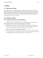
2.1 Appropriate Usage
The anemometer is a sensor intended to measure horizontal wind force outdoors. The provided
performance data can be processed by the Sunny SensorBox. Use the anemometer exclusively for
purposes indicated in the installation guide and the indicated application range. Use only SMA
Solar Technology AG original accessories or accessories recommended by SMA Solar Technology.
Read the accompanying documentation for the anemometer and the communication product
carefully before connecting the anemometer.
2.2 Safety Precautions
General safety precautions to avoid bodily harm
• Lay cables so that no one stands on them or trips over them.
• Work on rooftops entails a safety risk, and requires special safeguards to be implemented.
General information in order to avoid damage to the device.
• Damage to the sensors as a result of incorrect connection to the Sunny Boy Control Plus or
Sunny Central Control. Before connecting, read the corresponding installation guide and use
the enclosed circuit diagram when commissioning the Sunny Central Control.
• Integrate the sensor into the existing lightning protection.
• Protect your PV plant components against overvoltage from outside by connecting the sensors
to an overvoltage protector. When using the sensors with the Sunny Central, the corresponding
overvoltage protectors can be ordered as an option from Sunny Central.
Installation Guide
Windsensor-IEN101010
5
Unpacking
SMA Solar Technology AG
3 Unpacking
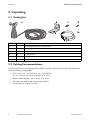
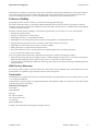
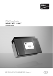
3.1 Packing List
Position
A
B
C
D
E
F
Number
1
1
2
2
2
2
Description
Anemometer with 3 m output cable
Mounting angle
Screws
Screw anchor
Straps
Washers
3.2 Cabling Recommendations
In the event that the pre-configured output cable is too short, please note the following information
when purchasing a longer cable:
• Cross section: min. 2 x 0.25 mm², min. 2 x AWG 24
Tip: you can also use a 4-core line (4 x 0.25 mm²).
• External cable diameter: min. 4.5 mm, max. 6 mm
• The maximum cable length may not exceed 30 m
• UV resistant (for outdoor use only)
6
Windsensor-IEN101010
Installation Guide
SMA Solar Technology AG
Unpacking
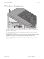
3.3 Selecting the Mounting Location
• The mounting location must not be sheltered from the wind or in the lee of objects such as
chimneys or satellite systems.
• The anemometer must be mounted in an upright position; otherwise, water can enter the
anemometer and destroy it.
• If possible, install the anemometer in the center of flat roofs. Installing the anemometer at the
edge of the roof may cause air turbulence that may distort the measuring results.
• Observe the pre-configured cable length of 3 m. The cable may be cut or extended to a
maximum of 30 m.
Installation Guide
Windsensor-IEN101010
7
Mounting the Device
SMA Solar Technology AG
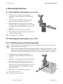
4 Mounting the Device
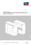
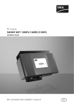
4.1 Mounting the anemometer on a mast
1. Determine the mounting position taking into
consideration the requirements of the mounting
location.
2. Attach the mounting angle using the enclosed
clamp at the top end of the mast (see ➀ ).
3. Place anemometer with the screws in the wide
recesses of the mounting angle (see ➁ ) and rotate
the anemometer up to the end of the narrow recess
(see ➂ ).
4. Tighten the screws below the anemometer.
5. Attach cables closely to the mast using cable ties or
similar attaching material.
☑ The anemometer is mounted.
4.2 Mounting the anemometer on a wall
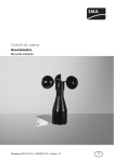
4.2.1 Wall Mounting with Mounting Angle
If the anemometer is mounted directly on the wall, turbulence may occur, which reduces
the precision of measurements.
We recommend using a wall mounting bracket for wall mounting (see chapter4.2.2 ”Wall
Mounting with Wall Mounting Bracket” (page 9)). The wall mounting bracket enlarges the
distance to the wall and avoids turbulence. The accuracy of measurements is increased.
1. Determine the mounting position taking into
consideration the requirements of the mounting
location.
2. Attach the mounting angle on the lateral end of the
wall using screws and screw anchors (see ➀ ).
3. Place the anemometer including screws into the
wide recesses of the mounting angle (see ➁ ) and
rotate the anemometer to the end of the narrow
recesses (see ➂ ).
4. Tighten the screws below the anemometer.
5. Lay cables on the wall.
☑ The anemometer is mounted.
8
Windsensor-IEN101010
Installation Guide
SMA Solar Technology AG
Mounting the Device
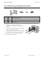
4.2.2 Wall Mounting with Wall Mounting Bracket
SMA order number:
Position
A
B
C
D
Number
1
4
4
4
Wall mounting bracket
Description
Wall mounting bracket
Hex screws
Washers
Screw anchor
The optional wall mounting bracket is required for wall mounting using the wall mounting bracket.
1. Determine the mounting position taking into
consideration the requirements of the mounting
location.
2. Attach the wall mounting bracket to the wall using
screws, screw anchors and washers.
3. Mounting the anemometer on a mast (see page 8).
4. Attach cables closely to the wall mounting bracket
using cable ties or similar attaching material.
☑ The anemometer is mounted.
Installation Guide
Windsensor-IEN101010
9
Electrical Connection
SMA Solar Technology AG
5 Electrical Connection
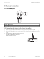
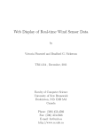
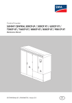
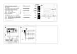
5.1 Circuit diagram
Position Description
A
Reed sensor
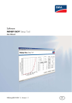
5.2 Connecting the Sensor to the Sunny SensorBox
1. Open Sunny SensorBox as described in the Sunny SensorBox Installation Guide.
2. Unscrew the cable gland's lock nut on the top left of the Sunny SensorBox and remove the filler
plugs.
3. Thread the sensor cable through the lock nut and
the cable gland at the top left into the
Sunny SensorBox enclosure.
10
Windsensor-IEN101010
Installation Guide
SMA Solar Technology AG
Electrical Connection
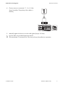
4. Connect sensor to connection "F3: Wind" of the
Sunny SensorBox. The polarity of the cables is
arbitrary.
5. Manually tighten the sleeve nut to the cable gland (torque: 0.8 Nm).
6. Lay the cable using suitable fastening material.
☑ The anemometer is connected. You can now put Sunny SensorBox into operation.
Installation Guide
Windsensor-IEN101010
11
Decommissioning
SMA Solar Technology AG
6 Decommissioning
6.1 Disassembling the Sensor
1. Reset the configuration of the sensor in the communication device.
2. Detach the sensor cable from the communication device.
3. Disassemble the sensor depending on the assembly type.
☑ The sensor is now disassembled.
6.2 Disposing of the Sensor
At the end of its service life, dispose of the sensor in accordance with the applicable disposal
regulations for electronic waste at the installation site at that time. Alternatively, send it back to
SMA Solar Technology with shipping paid by the sender, and labeled "ZUR ENTSORGUNG"
("for disposal").
12
Windsensor-IEN101010
Installation Guide
SMA Solar Technology AG
Technical data
7 Technical data
Mechanical data
Height
Base diameter
Cup diameter
Weight
160 mm
50 mm
134 mm
300 g
Measured values
Proportional frequency in relation to wind force
Accuracy
Measuring range*
Resolution**
Proportional frequency to wind force
100 Hz at 40 m/s
± 0.5 %
0.8 m/s to 40 m/s
0.4 m
100 Hz at 40 m/s
* 60 m/s are also possible briefly
** Wind run
Environmental conditions during operation*
Ambient temperature
Mounting location
– 25 °C to + 60 °C
Outdoors
* When free of ice
Installation Guide
Windsensor-IEN101010
13
Contact
SMA Solar Technology AG
8 Contact
If you have technical problems with our products, please contact our Service line. We require the
following information in order to provide you with the necessary assistance:
• Sensor model
• Communication device
• Measured values
Sunny Central
SMA Solar Technology AG
SMA Solar Technology AG
Sonnenallee 1
Sonnenallee 1
34266 Niestetal, Germany
34266 Niestetal, Germany
www.SMA.de
www.SMA.de
SMA Serviceline
SMA Serviceline
Inverters:
Tel. +49 561 9522 299
+49 561 9522 1499
Communication: +49 561 9522 2499
Fax +49 561 9522 3299
Fax:
+49 561 9522 4699
E‑Mail: [email protected]
E-Mail:
[email protected]
14
Windsensor-IEN101010
Installation Guide
SMA Solar Technology AG
Legal Restrictions
The information contained in this document is the property of SMA Solar Technology AG. Publishing its content, either partially or
in full, requires the written permission of SMA Solar Technology AG. Any internal company copying of the document for the
purposes of evaluating the product or its correct implementation is allowed and does not require permission.
Exclusion of liability
The general terms and conditions of delivery of SMA Solar Technology AG shall apply.
The content of these documents is continually checked and amended, where necessary. However, discrepancies cannot be
excluded. No guarantee is made for the completeness of these documents. The latest version is available online at www.SMA.de
or from the usual sales channels.
Guarantee or liability claims for damages of any kind are excluded if they are caused by one or more of the following:
• Damages during transportation
• Improper or inappropriate use of the product
• Operating the product in an unintended environment
• Operating the product whilst ignoring relevant, statutory safety regulations in the deployment location
• Ignoring safety warnings and instructions contained in all documents relevant to the product
• Operating the product under incorrect safety or protection conditions
• Altering the product or supplied software without authority
• The product malfunctions due to operating attached or neighboring devices beyond statutory limit values
• In case of unforeseen calamity or force majeure
The use of supplied software produced by SMA Solar Technology AG is subject to the following conditions:
• SMA Solar Technology AG rejects any liability for direct or indirect damages arising from the use of software developed by
SMA Solar Technology AG. This also applies to the provision or non-provision of support activities.
• Supplied software not developed by SMA Solar Technology AG is subject to the respective licensing and liability agreements
of the manufacturer.
SMA Factory Warranty
The current guarantee conditions come enclosed with your device. These are also available online at www.SMA.de and can be
downloaded or are available on paper from the usual sales channels if required.
Trademarks
All trademarks are recognized even if these are not marked separately. Missing designations do not mean that a product or brand
is not a registered trademark.
The Bluetooth® word mark and logos are registered trademarks owned by Bluetooth SIG, Inc. and any use of such marks by SMA
Solar Technology AG is under license.
SMA Solar Technology AG
Sonnenallee 1
34266 Niestetal
Germany
Tel. +49 561 9522-0
Fax +49 561 9522-100
www.SMA.de
E-Mail: [email protected]
© 2004 to 2010 SMA Solar Technology AG. All rights reserved
Installation Guide
Windsensor-IEN101010
15
4."4PMBS5FDIOPMPHZ"(
XXX4."EF