1
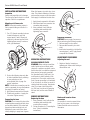
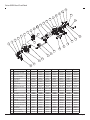
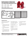
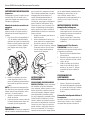
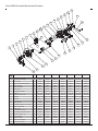
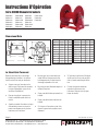
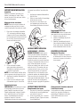
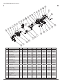
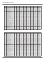
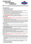
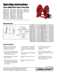
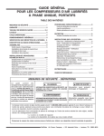
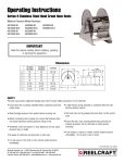
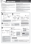
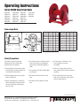
Operating Instructions
Series 30000 Hand Crank Reels
CA30106 L
CA30112 L
CA30118 L
CA30122 L
CA30128 L
CA32106 L
CA32106 M
CA32112 L
CA32112 M
CA32118 L
CA32118 M
CA32122 L
CA32128 L
CA33106 L
CA33106 M
CA33112 L
CA33112 M
CA33118 L
CA33118 M
CA33122 L
CA33128 L
Dimensional Data
Part #
A
CA30106 L 19 3/4”
CA30112 L 25 3/4”
CA30118 L 31 3/4”
CA30122 L 35 3/4”
CA30128 L 40 3/4”
CA32106 L 19 3/4”
CA32106 M 19 3/4”
CA32112 L 25 3/4”
CA32112 M 25 3/4”
CA32118 L 31 3/4”
CA32118 M 31 3/4”
B
6”
12”
18”
22”
27”
6”
6”
12”
12”
18”
18”
D
9 3/4”
15 3/4”
21 3/4”
25 3/4”
30 3/4”
9 3/4”
9 3/4”
15 3/4”
15 3/4”
21 3/4”
21 3/4”
Part #
A
CA32122 L 35 3/4”
CA32128 L 40 3/4”
CA33106 L 19 3/4”
CA33106 M 19 3/4”
CA33112 L 25 3/4”
CA33112 M 25 3/4”
CA33118 L 31 3/4”
CA33118 M 31 3/4”
CA33122 L 35 3/4”
CA33128 L 40 3/4”
B
22”
27”
6”
6”
12”
12”
18”
18”
22”
27”
D
25 3/4”
30 3/4”
9 3/4”
9 3/4”
15 3/4”
15 3/4”
21 3/4”
21 3/4”
25 3/4”
30 3/4”
Safety Precautions
Personal injury and/or equipment
damage may result if proper safety
precautions are not observed.
• Do not play pranks on other personnel.
Even low pressure is very dangerous
and can cause irrepairable damage or
death.
• Ensure that the reel has been properly
installed before connecting supply line
(see installation instructions).
• Do not wear loose fitting clothing while
operating reel.
• Bleed fluid/gas pressure from system
before servicing reel.
• Be aware of other personnel in work
area.
• Before connecting reel to supply line
ensure that supply line pressure does
not exceed maximum rated working
pressure of reel.
• Be aware of other machinery in work
area.
• If a leak occurs in the hose or reel,
remove supply line pressure
immediately.
• If the reel is power driven check for
loose, frayed, and/or broken wires before
operating.
• Treat and respect a hose reel as any
other piece of machinery, observing all
common safety practices.
Form# 837-696A Rev: 5/2013
Reelcraft Industries, Inc. • 2842 E Business Hwy 30, Columbia City, IN 46725
Ph: 800-444-3134 / 260-248-8188 • Fax: 800-444-4587 / 260-248-2605
Customer Service: 855-634-9109 • [email protected] • www.reelcraft.com
Series 30000 Hand Crank Reels
INSTALLATION INSTRUCTIONS
Inspection
Unpack and inspect the reel for damage.
Turn the reel by hand to check for smooth
operation. Check for completeness.
Mounting of all hose reels
NOTE: Ensure that mounting surface is
flat to prevent binding on reel after it is
mounted.
When fluid appears at control valve, close
valve. This prevents flattening of the hose
and excessive pressure on the drum when
fluid supply is reinitialized at a later time.
1. Apply thread compound to all threads.
2. Hand thread male hose connector into
connecting tube assembly.
3. Using a wrench, firmly hold onto
connecting tube assembly while
tightening hose connector.
1. Two 1/2” diameter mounting holes are
located at the base of each side
support panel (2 each). Mount reel
using four (customer supplied) bolts;
tightening them securely to ensure a
solid, rigid attachment.
Replacing the swivel
CAUTION: Remove supply line pressure
before performing the following procedure.
1. Remove supply line from swivel.
2. Remove swivel assembly from inlet
shaft.
3. Install swivel assembly to inlet shaft by
reversing steps 1 and 2. Apply thread
compound to all threads.
OPERATING INSTRUCTIONS
2. Perform the following steps only after
all other installation steps, pertaining
to your particular reel, are
accomplished. Refer to page 4 for
special instructions.
NOTE: A flexible hose connection must be
used to compensate for any offset between
the supply line and the reel swivel.
3. Apply thread compound to all threads.
4. Thread male connector of supply line
into swivel. Tighten securely.
Connecting the hose
CAUTION: Do not connect the hose to the
connecting tube assembly until after hose
reel has been installed. Fully extend and
charge hose before winding on ot reel.
Momentarily open control valve, when
initially charging, to purge hose of gases.
Page 2
WARNING-PREVENT STATIC
SPARKING: When working around flammable liquids such as solvents, paints,
chemicals or petroleum products, ensure
that the hose reel, hose and the equipment
being serviced are properly grounded.
Use grounded hose(s) (static wire). Use
an ohmmeter to check continuity of the
ground circuit. Fire and/or explosion can
result if proper grounding is not achieved.
If reel is power or air driven, be careful of
chain/sprocket drive system. Keep hands
clear. Do not wear loose fitting clothing. Pull hose from the reel by grasping
the hose itself, not the control handle or
swivel.
SERVICE INSTRUCTIONS
Replacing the hose
1. Using a wrench, firmly hold onto the
connecting tube assembly while
removing hose connector.
2. Follow procedures for “Connecting the
hose” (refer to installation
instructions).
ADJUSTMENT PROCEDURES
Adjusting the reel
1. Adjust reel drag by loosening or
tightening set screw on hub casting on
manual driven reel.
Hand crank to motor driven
conversion
It is possible to convert a manual driven
hose reel to a power or air driven type.
Contact Reelcraft customer service for
information.
www.reelcraft.com
Series 30000 Hand Crank Reels
16
7
15
17
13
2
6
14
12
18
13
11
10
7
5
3
8
9
6
19
4
2
2
20
8
1
3
21
22
23
8
7
24
13
13
20
ITEM
1
2
3
4
5
6
7
8
9
10
11
12
13
14
15
16
17
18
19
20
21
22
23
24
DESCRIPTION
QTY. CA30106 L CA30112 L CA30118 L CA30122 L CA30128 L CA32106 L CA32106 M
Swivel assembly
1
None
None
None
None
None
600888
S602033
Screw, 5/16-12 x 5/8”
9
S317-31
S317-31
S317-31
S317-31
S317-31
S317-31
S317-31
Side frame
2
260403
260403
260403
260403
260403
260403
260403
Set screw 3/8 brass
1
300099
300099
300099
300099
300099
300099
300099
Nut, 5/16-18
8
S85-7
S85-7
S85-7
S85-7
S85-7
S85-7
S85-7
Spool flange
2
S260399-3 S260399-3 S260399-3 S260399-3 S260399-3 S260399-3 S260399-3
Snap ring
3
300007
300007
300007
300007
300007
300007
300007
Inlet assembly
1
600327-2
600327-2
600327-2
600327-2
600327-2
600327-1
600327-1
O-ring
1
S211-120
S211-120
S211-120
S211-120
S211-120
S211-120
S211-120
Screw, 5/16-18 x 3/4”
4
S7-51
S7-51
S7-51
S7-51
S7-51
S7-51
S7-51
Tie rod
4
260402-100 260402-200 260402-300 260402-400 260402-500 260402-100 260402-100
Spacer
4
260401-1
260401-2
S260401-3
260401-4
260401-5
260401-1
260401-1
S600640
S600640
S600640
S600640
S600640
S600640
Hub & bushing assembly
3
S600640
Set screw
2
300006
300006
300006
300006
300006
300006
300006
Lock handle assembly
1
S280109
S280109
S280109
S280109
S280109
S280109
S280109
Set screw 3/8 square head 1
300089
300089
300089
300089
300089
300089
300089
Snap ring
1
S137-4
S137-4
S137-4
S137-4
S137-4
S137-4
S137-4
Crank handle assembly
1
S600102
S600102
S600102
S600102
S600102
S600102
S600102
Shaft / snap ring assembly 1
602242
602242
602242
602242
602242
602242
602242
Screw, 5/16-18 x 1/2”
8
S2-51
S2-51
S2-51
S2-51
S2-51
S2-51
S2-51
Nut, 5/16-18
8
300107
300107
300107
300107
300107
300107
300107
Cross brace
2
261501-1
261501-2
261501-3
261501-4
261501-5
261501-1
261501-1
Reducer bushing
4
None
None
None
None
None
None
None
Screw, 1/4-20 x 5/8”
3
S2-42
S2-42
S2-42
S2-42
S2-42
S2-42
S2-42
www.reelcraft.com
Page 3
Series 30000 Hand Crank Reels
ITEM
1
2
3
4
5
6
7
8
9
10
11
12
13
14
15
16
17
18
19
20
21
22
23
24
DESCRIPTION
QTY. CA32112 L CA32112 M CA32118 L CA32118 M CA32122 L CA32128 L CA33106 L
Swivel assembly
1
600888
S602033
600888
S602033
600888
600888
S602026
Screw, 5/16-12 x 5/8”
9
S317-31
S317-31
S317-31
S317-31
S317-31
S317-31
S317-31
Side frame
2
260403
260403
260403
260403
260403
260403
260403
Set screw 3/8 brass
1
300099
300099
300099
300099
300099
300099
300099
Nut, 5/16-18
8
S85-7
S85-7
S85-7
S85-7
S85-7
S85-7
S85-7
Spool flange
2
S260399-3 S260399-3 S260399-3 S260399-3 S260399-3 S260399-3 S260399-3
Snap ring
3
300007
300007
300007
300007
300007
300007
300007
Inlet assembly
1
600327-1
600327-1
600327-1
600327-1
600327-1
600327-1
600327-2
O-ring
1
S211-120
S211-120
S211-120
S211-120
S211-120
S211-120
S211-120
Screw, 5/16-18 x 3/4”
4
S7-51
S7-51
S7-51
S7-51
S7-51
S7-51
S7-51
Tie rod
4
260402-200 260402-200 260402-300 260402-300 260402-400 260402-400 260402-100
Spacer
4
260401-2
260401-2
S260401-3 S260401-3
260401-4
260401-5
260401-1
S600640
S600640
S600640
S600640
S600640
S600640
Hub & bushing assembly
3
S600640
Set screw
2
300006
300006
300006
300006
300006
300006
300006
Lock handle assembly
1
S280109
S280109
S280109
S280109
S280109
S280109
S280109
Set screw 3/8 square head 1
300089
300089
300089
300089
300089
300089
300089
Snap ring
1
S137-4
S137-4
S137-4
S137-4
S137-4
S137-4
S137-4
Crank handle assembly
1
S600102
S600102
S600102
S600102
S600102
S600102
S600102
Shaft & snap ring assembly 1
602242
602242
602242
602242
602242
602242
602242
Screw, 5/16-18 x 1/2”
8
S2-51
S2-51
S2-51
S2-51
S2-51
S2-51
S2-51
Nut, 5/16-18
8
300107
300107
300107
300107
300107
300107
300107
Cross brace
2
261501-2
261501-2
261501-3
261501-3
261501-4
261501-5
261501-1
Reducer bushing
4
None
None
None
None
None
None
None
Screw, 1/4-20 x 5/8”
3
S2-42
S2-42
S2-42
S2-42
S2-42
S2-42
S2-42
ITEM
1
2
3
4
5
6
7
8
9
10
11
12
13
14
15
16
17
18
19
20
21
22
23
24
DESCRIPTION
QTY. CA33106 M CA33112 L CA33112 M CA33118 L CA33118 M CA33122 L CA33128 L
Swivel assembly
1
S602026
S602026
S602026
S602026
S602026
S602026
S602026
Screw, 5/16-12 x 5/8”
9
S317-31
S317-31
S317-31
S317-31
S317-31
S317-31
S317-31
Side frame
2
260403
260403
260403
260403
260403
260403
260403
Set screw 3/8 brass
1
300099
300099
300099
300099
300099
300099
300099
Nut, 5/16-18
8
S85-7
S85-7
S85-7
S85-7
S85-7
S85-7
S85-7
Spool flange
2
S260399-3 S260399-3 S260399-3 S260399-3 S260399-3 S260399-3 S260399-3
Snap ring
3
300007
300007
300007
300007
300007
300007
300007
Inlet assembly
1
600327-2
600327-2
600327-2
600327-2
600327-2
600327-2
600327-2
O-ring
1
S211-120
S211-120
S211-120
S211-120
S211-120
S211-120
S211-120
Screw, 5/16-18 x 3/4”
4
S7-51
S7-51
S7-51
S7-51
S7-51
S7-51
S7-51
Tie rod
4
260402-100 260402-200 260402-200 260402-300 260402-300 260402-400 260402-500
Spacer
4
260401-1
260401-2
260401-2
S260401-3 S260401-3
260401-4
260401-5
S600640
S600640
S600640
S600640
S600640
S600640
Hub & bushing assembly
3
S600640
Set screw
2
300006
300006
300006
300006
300006
300006
300006
Lock handle assembly
1
S280109
S280109
S280109
S280109
S280109
S280109
S280109
Set screw 3/8 square head 1
300089
300089
300089
300089
300089
300089
300089
Snap ring
1
S137-4
S137-4
S137-4
S137-4
S137-4
S137-4
S137-4
Crank handle assembly
1
S600102
S600102
S600102
S600102
S600102
S600102
S600102
Shaft & snap ring assembly 1
602242
602242
602242
602242
602242
602242
602242
Screw, 5/16-18 x 1/2”
8
S2-51
S2-51
S2-51
S2-51
S2-51
S2-51
S2-51
Nut, 5/16-18
8
300107
300107
300107
300107
300107
300107
300107
Cross brace
2
261501-1
261501-2
261501-2
261501-3
261501-3
261501-4
261501-5
Reducer bushing
4
None
None
None
None
None
None
None
Screw, 1/4-20 x 5/8”
3
S2-42
S2-42
S2-42
S2-42
S2-42
S2-42
S2-42
Page 4
www.reelcraft.com
Instrucciones de Operacion
Series 30000 Accionado Manualmente Carreteles
CA30106 L
CA30112 L
CA30118 L
CA30122 L
CA30128 L
CA32106 L
CA32106 M
CA32112 L
CA32112 M
CA32118 L
CA32118 M
CA32122 L
CA32128 L
CA33106 L
CA33106 M
CA33112 L
CA33112 M
CA33118 L
CA33118 M
CA33122 L
CA33128 L
Dimensiones
Part #
A
CA30106 L 19 3/4”
CA30112 L 25 3/4”
CA30118 L 31 3/4”
CA30122 L 35 3/4”
CA30128 L 40 3/4”
CA32106 L 19 3/4”
CA32106 M 19 3/4”
CA32112 L 25 3/4”
CA32112 M 25 3/4”
CA32118 L 31 3/4”
CA32118 M 31 3/4”
B
6”
12”
18”
22”
27”
6”
6”
12”
12”
18”
18”
D
9 3/4”
15 3/4”
21 3/4”
25 3/4”
30 3/4”
9 3/4”
9 3/4”
15 3/4”
15 3/4”
21 3/4”
21 3/4”
Part #
A
CA32122 L 35 3/4”
CA32128 L 40 3/4”
CA33106 L 19 3/4”
CA33106 M 19 3/4”
CA33112 L 25 3/4”
CA33112 M 25 3/4”
CA33118 L 31 3/4”
CA33118 M 31 3/4”
CA33122 L 35 3/4”
CA33128 L 40 3/4”
B
22”
27”
6”
6”
12”
12”
18”
18”
22”
27”
D
25 3/4”
30 3/4”
9 3/4”
9 3/4”
15 3/4”
15 3/4”
21 3/4”
21 3/4”
25 3/4”
30 3/4”
Serguridad Personal
Acidentes personales y/o equipos dandados
pueden resultar si una de las seguridades
apropiadas y percausiones no son
obervadas.
• Asegurese que el carretel este apropiadamente instalado antes de conectar la
linea de provision (leas instrucciones
• de instalacion).
• Desaloje la presion del fluido/gas del
el sistema antes de darle servicio al
• carretel.
• Antes de conectar el carretel a la linea
de provision asegurese que la presion
de esta linea de provision ne exeda el
maximo de capacidad de presion del
carretel.
• No jeugue o haga bromas con otra
personas. Tambien los gases abaja persion son perligrosos y pueden causar
• danos inreparables o la muerte.
• No use ropa o vestidos sueltos cuando
• este operando el carretel.
• Este prevenido de otro personal en el
• area de trabajo.
• Si el carretel es de poder motorizado
revise por cables sueltos, gastados
• antes de operar.
• Trate y respete el carretel de mangueracomo otra pieza de maquinaria, observando todas las practicas comunes de
seguirdad.
• Este prevenido de orta maquinaria en el
• area de trabajo.
• Si una gotera ocurre en la manguera o
en el carretel remueva la linead deprovision de presion de presion inmediatamente.
•
•
Page 5
Reelcraft Industries, Inc. • 2842 E Business Hwy 30, Columbia City, IN 46725
Ph: 800-444-3134 / 260-248-8188 • Fax: 800-444-4587 / 260-248-2605
Customer Service: 855-634-9109 • [email protected] • www.reelcraft.com
Form# 837-696A Rev: 5/2013
Series 30000 Accionado Manualmente Carreteles
INSTRUCCIONES DE INSTALACION
Inspeccion
Desempaque el carretel y inspeccione por
cualquier dano. Gire el carretel con la
mano para chequear una operacion suave.
Chequee completamente.
Montaje de todos los carreteles de
manguera
NOTA: Asegurese de que la superficie
donde se monta es lisa para prevenir el
doblamiento del carretel despues de la
montura.
1. Dos de los orificios de ensamblaje d
1/2” de diametro estan hubicados a
cada lado de el panel de soporte(dos).
Monte el carretel usando cuatro tornil
los (proveidos al cliente). Aptietelos
para asegurar una solida y rigida
union.
2. Realize los siguientes pasos solamente depues de todos los otros
pasos de instalacion pertenecientes a
asu carretel en particular, sean realizados.
NOTA: Una coneccion de manguera flexible debe de ser para compensar cualquier
balance entre la linea de abastesi, iento o
provision y el carretel giratorio.
3. Aplique el compuesto para tuercas
atodas las tuercas.
4. Inserte la tuerca al conector macho de
la linea de abastecimiento dentro del
torniquete, apriete seguramente.
Conecte La Manguera
PRECAUCION: No conecte la manguera al
tubo de coneccion montado hasta despues
Page 6
que el carretel de la manguera sea instalado. Extienda completamente y cargue la
manguera antes de enrrollarla en el
carretel. Momentaneamente habra el
control de la valvula cuando cargue
inicialmente, para purgar la manguera de
gases. Cuando el fluido aparece en la
valvula de control, cierre la valvula. Esto
previne el aplanamiento de la anguera y
execiva presion en el tambor curando el
abastecimiento de fluidos son reiniziados
tiempo mas tarde.
1. Aplique el compuesto para tuercas a
todas las tuercas.
2. Inserte manualmente la tuerca al conector macho de la manguera dentro
del tubo de coneccion de montaje.
3. Usando una llave de tuercas, sostenga
firmemente sobre el tubo de coneccion de montaje cuando apriete el
conector de la manguera.
INSTRUCCIONES DE
OPERAMIENTO
PRECAUCIONES-PREVENCIONES DE
CHISPA ESTATICA: Cuando este trabajando alrededor de liquidos inflamables
como solventes, pinturas, quimicos o productos de petroleo, asegurece que el carretel de la manguera, manguera y equipo
esten devidamente conectados a tierra.
Use la(s) manguera(s) conectadas a tierra
(calbes electrico(s) estatico(s)). Use un
ohmetro medidor de resistencia electrica
para revisar la continuidad del circuito de
coneccion a tierra. Fuego y/o explocion
pueden resultar si una propia coneccion
a tierra no es realizada. Si el carretel es
operado con aire a presion tenga cuidado
con la cadena dentada manejada presion.
Mantenga las manos libres, no use
ropa o vestidos sueltos. Hale la
mangueras del carretel agarrandola de la
misma y no de el control o de el eje
giratorio.
INSTRUCCIONES DE SERVICIO
Reemplazo De La Manguera
1. Usando un llave de tuercas, firmemente sugete el tubo de conecicon de
montaje por untiempo removiendo el
conector de manguera.
2. Siga el proceso para “Conecciones
de manguera” (mire intrucciones de
instalacion).
Reemplazando El Eje Giratorio
PRECAUCION: Remueva la linea de
abastecimiento de presion minetras realiza
el siguiente procedimiento.
1. Remueva la linea de abastecimiento
del eje giratorio.
2. Remueva el eje de montaje del eje giratorio la entrada de el tunel o hueco
origicio del eje.
3. Instale el montaje del eje firatorio
dentro de el tunel del eje devolviendose por os pasos 2,1. Aplique
compnente de tuercas a todas las
tuercas.
PROCEDIMIENTO DE
AJUSTAMIENTO
Ajustamiento del carretel
1. Ajustar el dispositivo de seguridad
del carretel desagustando y ajustando
el conjunto de tornillos en la cubierta,
en los carreteles conducidos manualmente.
Palanca De Codo Operada A Motor O
Transmission
Esposible convertir un motor de manguera
manual a uno electrico o aire. Contacte la
compania Reelcraft para imformacion.
www.reelcraft.com
Series 30000 Accionado Manualmente Carreteles
16
7
15
17
13
2
6
14
12
18
13
11
10
7
5
3
8
9
6
19
4
2
2
20
8
1
3
21
22
23
8
7
24
13
13
20
ARTICULO
1
2
3
4
5
6
7
8
9
10
11
12
13
14
15
16
17
18
19
20
21
22
23
24
DESCRIPCION
CTD
Ensamblaje del eje giratoria
Tornillo, 5/16-12 x 5/8”
Lado el marco
Juego de tornillo de bronce 3/8
Tuerca, 5/16-18
Platillo del carretel
Aro de resorte
Ensamblaje de entrada
Arendela
Tornilla, 5/16-18 x 3/4”
Separador
Espaciador
Ensamblaje de la campana y boquilla
Juego de tornillo
Ensamblaje del sequro de la manija
Juego de tornillo 3/8
Aro de resorte
Ensamblaje de la manija
Eje y montaje para anillo elástico
Tornillo, 5/16-18 x 1/2”
Tuerca, 5/16-18
Miembro cruzado
Reducido de la boquilla
Tornillo, 1/4-20 x 5/8”
1
9
2
1
8
2
3
1
1
4
4
4
3
2
1
1
1
1
1
8
8
2
4
3
www.reelcraft.com
CA30106 L
CA30112 L
CA30118 L
CA30122 L
CA30128 L
CA32106 L CA32106 M
-----------------------------------600888
S602033
S317-31
S317-31
S317-31
S317-31
S317-31
S317-31
S317-31
260403
260403
260403
260403
260403
260403
260403
300099
300099
300099
300099
300099
300099
300099
S85-7
S85-7
S85-7
S85-7
S85-7
S85-7
S85-7
S260399-3 S260399-3 S260399-3 S260399-3 S260399-3 S260399-3 S260399-3
300007
300007
300007
300007
300007
300007
300007
600327-2
600327-2
600327-2
600327-2
600327-2
600327-1
600327-1
S211-120
S211-120
S211-120
S211-120
S211-120
S211-120
S211-120
S7-51
S7-51
S7-51
S7-51
S7-51
S7-51
S7-51
260402-100 260402-200 260402-300 260402-400 260402-500 260402-100 260402-100
260401-1
260401-2
S260401-3
260401-4
260401-5
260401-1
260401-1
S600640
S600640
S600640
S600640
S600640
S600640
S600640
300006
300006
300006
300006
300006
300006
300006
S280109
S280109
S280109
S280109
S280109
S280109
S280109
300089
300089
300089
300089
300089
300089
300089
S137-4
S137-4
S137-4
S137-4
S137-4
S137-4
S137-4
S600102
S600102
S600102
S600102
S600102
S600102
S600102
602242
602242
602242
602242
602242
602242
602242
S2-51
S2-51
S2-51
S2-51
S2-51
S2-51
S2-51
300107
300107
300107
300107
300107
300107
300107
261501-1
261501-2
261501-3
261501-4
261501-5
261501-1
261501-1
-------------------------------------------------S2-42
S2-42
S2-42
S2-42
S2-42
S2-42
S2-42
Page 7
Series 30000 Accionado Manualmente Carreteles
ARTICULO
1
2
3
4
5
6
7
8
9
10
11
12
13
14
15
16
17
18
19
20
21
22
23
24
ARTICULO
1
2
3
4
5
6
7
8
9
10
11
12
13
14
15
16
17
18
19
20
21
22
23
24
DESCRIPCION
CTD
Ensamblaje del eje giratoria
Tornillo, 5/16-12 x 5/8”
Lado el marco
Juego de tornillo de bronce 3/8
Tuerca, 5/16-18
Platillo del carretel
Aro de resorte
Ensamblaje de entrada
Arendela
Tornilla, 5/16-18 x 3/4”
Separador
Espaciador
Ensamblaje de la campana y boquilla
Juego de tornillo
Ensamblaje del sequro de la manija
Juego de tornillo 3/8
Aro de resorte
Ensamblaje de la manija
Eje y montaje para anillo elástico
Tornillo, 5/16-18 x 1/2”
Tuerca, 5/16-18
Miembro cruzado
Reducido de la boquilla
Tornillo, 1/4-20 x 5/8”
1
9
2
1
8
2
3
1
1
4
4
4
3
2
1
1
1
1
1
8
8
2
4
3
DESCRIPCION
Ensamblaje del eje giratoria
Tornillo, 5/16-12 x 5/8”
Lado el marco
Juego de tornillo de bronce 3/8
Tuerca, 5/16-18
Platillo del carretel
Aro de resorte
Ensamblaje de entrada
Arendela
Tornilla, 5/16-18 x 3/4”
Separador
Espaciador
Ensamblaje de la campana y boquilla
Juego de tornillo
Ensamblaje del sequro de la manija
Juego de tornillo 3/8
Aro de resorte
Ensamblaje de la manija
Eje y montaje para anillo elástico
Tornillo, 5/16-18 x 1/2”
Tuerca, 5/16-18
Miembro cruzado
Reducido de la boquilla
Tornillo, 1/4-20 x 5/8”
Page 8
CA32112 L CA32112 M CA32118 L CA32118 M CA32122 L
CA32128 L
600888
S602033
600888
S602033
600888
600888
S602026
S317-31
S317-31
S317-31
S317-31
S317-31
S317-31
S317-31
260403
260403
260403
260403
260403
260403
260403
300099
300099
300099
300099
300099
300099
300099
S85-7
S85-7
S85-7
S85-7
S85-7
S85-7
S85-7
S260399-3 S260399-3 S260399-3 S260399-3 S260399-3 S260399-3 S260399-3
300007
300007
300007
300007
300007
300007
300007
600327-1
600327-1
600327-1
600327-1
600327-1
600327-1
600327-2
S211-120
S211-120
S211-120
S211-120
S211-120
S211-120
S211-120
S7-51
S7-51
S7-51
S7-51
S7-51
S7-51
S7-51
260402-200 260402-200 260402-300 260402-300 260402-400 260402-400 260402-100
260401-2
260401-2
S260401-3 S260401-3
260401-4
260401-5
260401-1
S600640
S600640
S600640
S600640
S600640
S600640
S600640
300006
300006
300006
300006
300006
300006
300006
S280109
S280109
S280109
S280109
S280109
S280109
S280109
300089
300089
300089
300089
300089
300089
300089
S137-4
S137-4
S137-4
S137-4
S137-4
S137-4
S137-4
S600102
S600102
S600102
S600102
S600102
S600102
S600102
602242
602242
602242
602242
602242
602242
602242
S2-51
S2-51
S2-51
S2-51
S2-51
S2-51
S2-51
300107
300107
300107
300107
300107
300107
300107
261501-2
261501-2
261501-3
261501-3
261501-4
261501-5
261501-1
-------------------------------------------------S2-42
S2-42
S2-42
S2-42
S2-42
S2-42
S2-42
CTD CA33106 M CA33112 L CA33112 M CA33118 L CA33118 M CA33122 L
1
9
2
1
8
2
3
1
1
4
4
4
3
2
1
1
1
1
1
8
8
2
4
3
CA33106 L
CA33128 L
S602026
S602026
S602026
S602026
S602026
S602026
S602026
S317-31
S317-31
S317-31
S317-31
S317-31
S317-31
S317-31
260403
260403
260403
260403
260403
260403
260403
300099
300099
300099
300099
300099
300099
300099
S85-7
S85-7
S85-7
S85-7
S85-7
S85-7
S85-7
S260399-3 S260399-3 S260399-3 S260399-3 S260399-3 S260399-3 S260399-3
300007
300007
300007
300007
300007
300007
300007
600327-2
600327-2
600327-2
600327-2
600327-2
600327-2
600327-2
S211-120
S211-120
S211-120
S211-120
S211-120
S211-120
S211-120
S7-51
S7-51
S7-51
S7-51
S7-51
S7-51
S7-51
260402-100 260402-200 260402-200 260402-300 260402-300 260402-400 260402-500
260401-1
260401-2
260401-2
S260401-3 S260401-3
260401-4
260401-5
S600640
S600640
S600640
S600640
S600640
S600640
S600640
300006
300006
300006
300006
300006
300006
300006
S280109
S280109
S280109
S280109
S280109
S280109
S280109
300089
300089
300089
300089
300089
300089
300089
S137-4
S137-4
S137-4
S137-4
S137-4
S137-4
S137-4
S600102
S600102
S600102
S600102
S600102
S600102
S600102
602242
602242
602242
602242
602242
602242
602242
S2-51
S2-51
S2-51
S2-51
S2-51
S2-51
S2-51
300107
300107
300107
300107
300107
300107
300107
261501-1
261501-2
261501-2
261501-3
261501-3
261501-4
261501-5
-------------------------------------------------S2-42
S2-42
S2-42
S2-42
S2-42
S2-42
S2-42
www.reelcraft.com
Instructions D’Opération
Série 30000 Manuels Enrouleurs
CA30106 L
CA30112 L
CA30118 L
CA30122 L
CA30128 L
CA32106 L
CA32106 M
CA32112 L
CA32112 M
CA32118 L
CA32118 M
CA32122 L
CA32128 L
CA33106 L
CA33106 M
CA33112 L
CA33112 M
CA33118 L
CA33118 M
CA33122 L
CA33128 L
Dimensional Data
Part #
A
CA30106 L 19 3/4”
CA30112 L 25 3/4”
CA30118 L 31 3/4”
CA30122 L 35 3/4”
CA30128 L 40 3/4”
CA32106 L 19 3/4”
CA32106 M 19 3/4”
CA32112 L 25 3/4”
CA32112 M 25 3/4”
CA32118 L 31 3/4”
CA32118 M 31 3/4”
B
6”
12”
18”
22”
27”
6”
6”
12”
12”
18”
18”
D
9 3/4”
15 3/4”
21 3/4”
25 3/4”
30 3/4”
9 3/4”
9 3/4”
15 3/4”
15 3/4”
21 3/4”
21 3/4”
Part #
A
CA32122 L 35 3/4”
CA32128 L 40 3/4”
CA33106 L 19 3/4”
CA33106 M 19 3/4”
CA33112 L 25 3/4”
CA33112 M 25 3/4”
CA33118 L 31 3/4”
CA33118 M 31 3/4”
CA33122 L 35 3/4”
CA33128 L 40 3/4”
B
22”
27”
6”
6”
12”
12”
18”
18”
22”
27”
D
25 3/4”
30 3/4”
9 3/4”
9 3/4”
15 3/4”
15 3/4”
21 3/4”
21 3/4”
25 3/4”
30 3/4”
La Sécurité du Personnel
Blessure personnel et/ou le dommage
d’équipement peut résulter si les précautions de sécurité ne sont pas observées.
• Assurez-vous que l’enrouleur est installé comme il faut avant de connecter
le tuyau d’alimentation (voyez les instructions d’installation).
•
• Évacuez du système la pression de
fluide/ combustible avant de faire le
service.
•
• Avant de connecter l’enrouleur au tuyau
d’alimentation, assurez-vous que la
pression ne dépasse pas la pression
maximum pour l’enrouleur.
• Ne jouez pas un tour aux autres personnel. Même la basse pression est
trés dangereuse et elle peut causer le
dommage irréparable ou le mort.
•
• Ne portez pas des vêtements amples en
utilisant l’enrouleur.
•
• Soyez conscient d’autres personnels au
travaille.
•
• Soyez conscient d’autres machines au
travaille.
•
• Si le tuyau ou l’enrouleur se met à fuir,
évacuez la pression du système immédiatement.
Page 9
Reelcraft Industries, Inc. • 2842 E Business Hwy 30, Columbia City, IN 46725
Ph: 800-444-3134 / 260-248-8188 • Fax: 800-444-4587 / 260-248-2605
Customer Service: 855-634-9109 • [email protected] • www.reelcraft.com
• Si l’enrouleur fonctionne à l’électricité,
vérifiez que les fils ne sont pas effilochés ou cassés avant chaque utilisation.
•
• Comme tout d’autres machines,
repectez et utilisez avec soin
l’enrouleur. Observez tous les practiques de sécurité.
Form# 837-696A Rev: 5/2013
Série 30000 Manuels Enrouleurs
INSTRUCTIONS D’INSTALLATION
Inspection
Déballez et inspectez l’enrouleur pour
déceler le dommage s’il existe. Faites
tourner l’enrouleur à la main pour vérifier
le bon fonctionnement.
Montage de tous enrouleurs
NOTEZ: Assurez-vous que la surface de
montage est plate pour éviter le coincement du tuyau après l’enrouleur est monté.
sive quand vous utilisez l’enrouleur plus
tard.
1. Appliques du matériau d’étanchéité à
tous les filets.
2. Enfilez le raccord mâle à l’assemblage
de tubulure de raccord.
3. Avec une clef, serrez bien ce raccord pendant que vous tenez bien
l’assemblage de tubulure de raccord.
1. Deux trous de montage du diamètre
1/2” se trouvent au base de chaquesupport de côté (2 pour chaque).Montez l’enrouleur avec 4 boulons (fournis
par le cliènt). Serrez-les biens pour
assurer une fixation solide.
INSTRUCTIONS D’OPÉRATION
2. Faites les étapes suivantes
après toutes autres instructions
d’installations sont faites pour votre
enrouleur en particulier.
NOTEZ: Un racord flexible doit être utilisé
pour compenser entre le tuyau et le pivot.
3. Appliquez du matériau d’étanchéité à
tous les filets.
4. Enfilez le raccord mâle de la ligne
d’alimentatin au pivot. Serrez bien.
Connection du tuyau
PRÉCAUTION: Ne connectez pas le tuyau
à l’assemblage du tubulure de raccord
avant d’installer l’enrouleur de tuyau.
Étendez entièrenment le tuyau et remplissez-le avant d’enrouler sur l’enrouleur.
Ouvrez momentanément la vanne de
régulation, fermez-la. Cela évite
l’aplatissage du tuyau et la pression excesPage 10
Remplacement de Pivot
PRÉCAUTION: Enlevez la pression du
tuyau avant de faire le procédé suivant.
1. Enlevez le tuyau du pivot.
2. Enlevez l’assemblage du pivot de
l’arbre d’entré.
3. IInstallez l’assemblage de pivot à
l’arbre d’entré enfaisant les étapes 1 à
2 par ordre inverse. Appliquéz du matériau d’étanchéité à tous les filets.
AVERTISSEMENT - ÉVITEZ LA
CHARGE STATIQUE: Quand vous travaillez près des liquides combustibles
come des dissolvants, des penitures, des
produits chimiques, ou des produits
de pétroles, assurez-vous que l’enrouleur,
le tuyau, et l’equipement sont tous mis à
terre. Utilisez des tuyaux mis à terre.
Utilisez un ohmètre pour vérifier la continuité du circuit. Si l’enrouleur n’est pas
correctement mis à terre, un feu ou une
explosion peur résulter. Si l’enrouleur
fonctionne à l’air ou à l’électicité, soyez
prudent du système de chaîne/de pignon.
Tenez vos mains loin du système. Ne
portez pas des vêtements amples. Tirez le
tuyau de l’enrouleur en empoignant le
tuyau, et non pas la poignée de régulation
ni le pivot.
PROCÉDÉS DE RÉGLAGES
INSTRUCTIONS D’ENTRETIEN
Changement de l’enrouleur manuel à
l’enrouleur à moteur.
Il est possible de modifier un enrouleur
manuel à un enrouleur électrique ou
pneumatique. Téléphonez ou écrivez à
l’usine de Reelcraft pour avoir de
l’information.
Remplacement des tuyaux
1. Avec une clef, tenez bien l’assemblage
de tubulure de raccord pendant que
vous enlevez le raccord.
2. Suivez les procédés pour “La raccordement de Tuyau” (Voyez les Instructions d’Installation).
Réglage de l’Enrouleur
1. Réglez la résistance en serrant ou
en désserrant la vis sans tête qui se
trouve sur le moyeu sur les enrouleurs manuels.
www.reelcraft.com
Série 30000 Manuels Enrouleurs
16
7
15
17
13
2
6
14
12
18
13
11
10
7
5
3
8
9
6
19
4
2
2
20
8
1
3
21
22
23
8
7
24
13
13
20
Article
1
2
3
4
5
6
7
8
9
10
11
12
13
14
15
16
17
18
19
20
21
22
23
24
DESCRIPTION
Assemblage de pivot
Vis, 5/16-12 x 5/8”
Cadre Latéral
Vis sans tête 3/8 en laiton
Écrou, 5/16-18
Tambour bridé
Dispositif de retenue
Assemblage d’entrée
Anneau en “O”
Vis, 5/16-18 x 3/4”
Farre d’accouplement
Pièce d’espacement
Quantité
1
9
2
1
8
2
3
1
1
4
4
4
Assemblage de moyeu et manchon
3
Vis sans tête
2
Assemblage de manche loquant
1
Vis sans tête 3/8
1
Dispositif de retenue
1
Assemblage de poignée de manivelle
1
Arbre et montage circlip
1
Vis, 5/16-18 x 1/2”
8
Écrou, 5/16-18
8
Traverse
2
Manchon de re’duction
4
Vis, 1/4-20 x 5/8”
3
www.reelcraft.com
CA30106 L CA30112 L CA30118 L CA30122 L CA30128 L CA32106 L CA32106 M
-----------------------------------600888
S602033
S317-31
S317-31
S317-31
S317-31
S317-31
S317-31
S317-31
260403
260403
260403
260403
260403
260403
260403
300099
300099
300099
300099
300099
300099
300099
S85-7
S85-7
S85-7
S85-7
S85-7
S85-7
S85-7
S260399-3 S260399-3 S260399-3 S260399-3 S260399-3 S260399-3 S260399-3
300007
300007
300007
300007
300007
300007
300007
600327-2
600327-2
600327-2
600327-2
600327-2
600327-1
600327-1
S211-120
S211-120
S211-120
S211-120
S211-120
S211-120
S211-120
S7-51
S7-51
S7-51
S7-51
S7-51
S7-51
S7-51
260402-100 260402-200 260402-300 260402-400 260402-500 260402-100 260402-100
260401-1
260401-2
S260401-3
260401-4
260401-5
260401-1
260401-1
S600640
S600640
S600640
S600640
S600640
S600640
S600640
300006
300006
300006
300006
300006
300006
300006
S280109
S280109
S280109
S280109
S280109
S280109
S280109
300089
300089
300089
300089
300089
300089
300089
S137-4
S137-4
S137-4
S137-4
S137-4
S137-4
S137-4
S600102
S600102
S600102
S600102
S600102
S600102
S600102
602242
602242
602242
602242
602242
602242
602242
S2-51
S2-51
S2-51
S2-51
S2-51
S2-51
S2-51
300107
300107
300107
300107
300107
300107
300107
261501-1
261501-2
261501-3
261501-4
261501-5
261501-1
261501-1
-------------------------------------------------S2-42
S2-42
S2-42
S2-42
S2-42
S2-42
S2-42
Page 11
Série 30000 Manuels Enrouleurs
Article
1
2
3
4
5
6
7
8
9
10
11
12
13
14
15
16
17
18
19
20
21
22
23
24
DESCRIPTION
Assemblage de pivot
Vis, 5/16-12 x 5/8”
Cadre Latéral
Vis sans tête 3/8 en laiton
Écrou, 5/16-18
Tambour bridé
Dispositif de retenue
Assemblage d’entrée
Anneau en “O”
Vis, 5/16-18 x 3/4”
Farre d’accouplement
Pièce d’espacement
Quantité
1
9
2
1
8
2
3
1
1
4
4
4
Assemblage de moyeu et manchon
3
Vis sans tête
2
Assemblage de manche loquant
1
Vis sans tête 3/8
1
Dispositif de retenue
1
Assemblage de poignée de manivelle
1
Arbre et montage circlip
1
Vis, 5/16-18 x 1/2”
8
Écrou, 5/16-18
8
Traverse
2
Manchon de re’duction
4
Vis, 1/4-20 x 5/8”
3
CA32112 L CA32112 M CA32118 L CA32118 M CA32122 L CA32128 L CA33106 L
600888
S602033
600888
S602033
600888
600888
S602026
S317-31
S317-31
S317-31
S317-31
S317-31
S317-31
S317-31
260403
260403
260403
260403
260403
260403
260403
300099
300099
300099
300099
300099
300099
300099
S85-7
S85-7
S85-7
S85-7
S85-7
S85-7
S85-7
S260399-3 S260399-3 S260399-3 S260399-3 S260399-3 S260399-3 S260399-3
300007
300007
300007
300007
300007
300007
300007
600327-1
600327-1
600327-1
600327-1
600327-1
600327-1
600327-2
S211-120
S211-120
S211-120
S211-120
S211-120
S211-120
S211-120
S7-51
S7-51
S7-51
S7-51
S7-51
S7-51
S7-51
260402-200 260402-200 260402-300 260402-300 260402-400 260402-400 260402-100
260401-2
260401-2
S260401-3 S260401-3
260401-4
260401-5
260401-1
S600640
S600640
S600640
S600640
S600640
S600640
S600640
300006
300006
300006
300006
300006
300006
300006
S280109
S280109
S280109
S280109
S280109
S280109
S280109
300089
300089
300089
300089
300089
300089
300089
S137-4
S137-4
S137-4
S137-4
S137-4
S137-4
S137-4
S600102
S600102
S600102
S600102
S600102
S600102
S600102
602242
602242
602242
602242
602242
602242
602242
S2-51
S2-51
S2-51
S2-51
S2-51
S2-51
S2-51
300107
300107
300107
300107
300107
300107
300107
261501-2
261501-2
261501-3
261501-3
261501-4
261501-5
261501-1
-------------------------------------------------S2-42
S2-42
S2-42
S2-42
S2-42
S2-42
S2-42
Article
1
2
3
4
5
6
7
8
9
10
11
12
13
14
15
16
17
18
19
20
21
22
23
24
DESCRIPTION
Assemblage de pivot
Vis, 5/16-12 x 5/8”
Cadre Latéral
Vis sans tête 3/8 en laiton
Écrou, 5/16-18
Tambour bridé
Dispositif de retenue
Assemblage d’entrée
Anneau en “O”
Vis, 5/16-18 x 3/4”
Farre d’accouplement
Pièce d’espacement
CA33106 M CA33112 L CA33112 M CA33118 L CA33118 M CA33122 L CA33128 L
S602026
S602026
S602026
S602026
S602026
S602026
S602026
S317-31
S317-31
S317-31
S317-31
S317-31
S317-31
S317-31
260403
260403
260403
260403
260403
260403
260403
300099
300099
300099
300099
300099
300099
300099
S85-7
S85-7
S85-7
S85-7
S85-7
S85-7
S85-7
S260399-3 S260399-3 S260399-3 S260399-3 S260399-3 S260399-3 S260399-3
300007
300007
300007
300007
300007
300007
300007
600327-2
600327-2
600327-2
600327-2
600327-2
600327-2
600327-2
S211-120
S211-120
S211-120
S211-120
S211-120
S211-120
S211-120
S7-51
S7-51
S7-51
S7-51
S7-51
S7-51
S7-51
260402-100 260402-200 260402-200 260402-300 260402-300 260402-400 260402-500
260401-1
260401-2
260401-2
S260401-3 S260401-3
260401-4
260401-5
S600640
S600640
S600640
S600640
S600640
S600640
S600640
300006
300006
300006
300006
300006
300006
300006
S280109
S280109
S280109
S280109
S280109
S280109
S280109
300089
300089
300089
300089
300089
300089
300089
S137-4
S137-4
S137-4
S137-4
S137-4
S137-4
S137-4
S600102
S600102
S600102
S600102
S600102
S600102
S600102
602242
602242
602242
602242
602242
602242
602242
S2-51
S2-51
S2-51
S2-51
S2-51
S2-51
S2-51
300107
300107
300107
300107
300107
300107
300107
261501-1
261501-2
261501-2
261501-3
261501-3
261501-4
261501-5
-------------------------------------------------S2-42
S2-42
S2-42
S2-42
S2-42
S2-42
S2-42
Page 12
Quantité
1
9
2
1
8
2
3
1
1
4
4
4
Assemblage de moyeu et manchon
3
Vis sans tête
2
Assemblage de manche loquant
1
Vis sans tête 3/8
1
Dispositif de retenue
1
Assemblage de poignée de manivelle
1
Arbre et montage circlip
1
Vis, 5/16-18 x 1/2”
8
Écrou, 5/16-18
8
Traverse
2
Manchon de re’duction
4
Vis, 1/4-20 x 5/8”
3
www.reelcraft.com