1
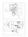
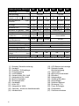
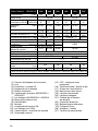
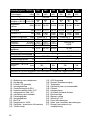
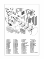
Vielen Dank, dass sie sich für MULTIBLITZ entschieden haben. Wir hoffen, dass ihnen die Arbeit mit diesem hochwertigen Qualitätsprodukt Freude bereiten wird. MULTIBLITZ Blitzgeräte werden ohne Ausnahme in Deutschland konstruiert und hergestellt. A C H T U N G! Lesen Sie diese Bedienungsanleitung genau durch, bevor sie dieses Produkt anwenden. Die Blitz-/ und Halogenröhren sowie Metallreflektoren werden im Betrieb sehr warm und können bei nicht sachgerechter Handhabung Verbrennungen verursachen. Das Öffnen des Gerätes könnte lebensgefährlich sein! Öffnen sie das Gerät unter keinen Umständen selber! Der Service sollte nur von einer autorisierten MULTIBLITZ Vertragswerkstatt durchgeführt werden. Decken Sie nicht die Ventilationsschlitze ab. Setzen Sie niemals Filter, Diffusionsmaterial oder ähnliches direkt auf die Blitz-/ oder Halogenröhre. Das Gerät darf auf keinen Fall Wasser, auch nicht Spritz- oder Tropfwasser, ausgesetzt werden. Das Gerät darf nicht mit ungeregelten Benzinoder Dieselgeneratoren betrieben werden. Bei ständigem Gebrauch sollte das Gerät einmal jährlich in einer autorisierten MULTIBLITZ Vertragswerkstatt überprüft werden. Zur Vermeidung einer möglichen Beeinträchtigung der Umwelt oder der menschlichen Gesundheit darf dieses Produkt nicht in den Hausmüll gegeben werden, um zu gewährleisten, dass es in einer umweltverträglichen Weise recycelt wird. Wenden Sie sich für Informationen zu Entsorgungs einrichtungen an die zuständige Behörde oder das Geschäft, in dem Sie dieses Produkt erworben haben. Bedienungsanleitung PROFILUX 200 - 400 - 600 Achtung: Vor der ersten Inbetriebnahme sowie nach einem Nichtgebrauch von 3 Monaten müssen die Blitzkondensatoren unbedingt formiert werden. Hierbei ist wie folgt vorzugehen: 1.Gerät einschalten 2.Gerät auf 1/1 (volle) Leistung stellen 3.Gerät NICHT abblitzen!!! 4.Gerät in diesem Zustand 1 Stunde einge schaltet lassen. 5. Das Halogenlicht dabei NICHT einschalten. Nach 1 Stunde sind die Blitzkondensatoren formiert, und das Gerät kann in Gebrauch genommen werden. 1. Grundausstattung Gerät mit steckbarer Blitzröhre, Halogenröhre mit Bajonettfassung Sockel B 15 d, Netzkabel, Synchronkabel, Schutzkappe, Ersatzsicherung. 2. Zubehör Diverse Wechselreflektoren, Faltreflektoren, Wabenfilter, Schirme, Abschirmklappen, Tubus, Stufenlinsenvorsatz, Stative. (Siehe Systemzeichnung auf der Rückseite). 3. Aufbau Die Geräte weisen eine 5/8“-Stativhülse (11) mit Feststellschraube (16) auf. Diese paßt auf alle Leuchtenstative mit 5/8“-Bolzen. Stative ohne diesen Bolzen benötigen den Adapter MA 151. Das Gerät kann nach Lösen des Handhebels (10) mit Handgriff (2) nach oben und unten gekippt werden. Arretieren des Gerätes durch Rechtsdrehung des nachstellbaren Handhebels (10). 4. Betriebsbereit machen Halogenröhre einsetzen (Siehe Punkt 12. dieser Bedienungsanleitung). Auf korrekten Sitz der Blitzröhre achten. Stecker des Netzkabels in 1 Buchse (8) in der Geräteunterseite einstecken und mit einer Netzsteckdose verbinden. Gerät mit dem roten Hauptschalter (6) einschalten, die rote LED (5) über dem Hauptschalter (6) leuchtet auf. Während der Aufladung leuchtet die LED (15) ganz schwach. Leuchtet die LED (15) permanent hell, ist das Gerät blitzbereit. Funktionen der LED (15): Leuchtet SCHWACH: Gerät wird geladen Leuchtet NICHT: Entladung (von hoher zu geringerer Energie oder Thermoschalter (Punkt 14.) hat angesprochen Leuchtet HELL, erlischt kurzzeitig Gerät ist blitzbereit 5. Netzanschluß Die Geräte werden vom Werk aus auf 220 240 V / 50 - 60 Hz oder 110 - 130 V / 50 - 60 Hz Wechselspannung eingestellt. Vor Anschluß an das Netz prüfen, ob Netzspannung mit der aufgedruckten Gerätespannung auf dem Typenschild (17) übereinstimmt. 6. Einschalten des Einstellichts Nach Einschalten mit dem roten Hauptschalter (6) kann das Halogenlicht mit dem dunkelgrauen Schalter (7) eingeschaltet werden. Ist das Halogenlicht eingeschaltet, leuchtet die LED über dem Schalter rot. Die Helligkeit des Halogenlichts ändert sich proportional zur eingestellten Blitzenergie. Profilux-Geräte mit 220 - 240 V: Profilux 200 ist vom Werk aus mit einer Halogenröhre 75W, Profilux 400 mit 150W und Profilux 600 mit 250W ausgerüstet. Innerhalb der Profilux-Serie sind diese Halogenröhren ohne technische Einschränkungen austauschbar. Ferner ist eine 250 W Halogenröhre auf besonderen Wunsch erhältlich, die ebenfalls in allen drei Geräten eingesetzt werden kann. Diese Halogenröhren benötigen keine spezielle Sicherung innerhalb der Geräte und bieten eine Brenndauer von 2000 h. Profilux-Geräte mit 110 - 130 V: Alle Geräte mit Halogenröhre 120 V / 200 W Sockel GX 6,35. Diese Halogenröhre erfordert eine eigene Sicherung F 2 A, die im vorderen Teil der Geräte untergebracht ist (24) sowie ein Pyrex-Schutzglas (25). Wechseln des Schutzglases siehe Punkt 15. 2 7. Leistungsregelung Mit Drehknopf (4) wird die Blitzenergie von ca. 12,5% bis 100% stufenlos geregelt (4 Blendenwerte sind einstellbar). Blitz- und Halogenlicht stehen in einem festen Verhältnis zueinander und werden proportional eingestellt. Beim Regeln von hoher auf niedrige Energie wird die überschüssige Energie innerhalb des Gerätes abgebaut, die LED (15) leuchtet in dieser Zeit NICHT. 8. 100% Einstellicht Mit Schalter (12) läßt sich das Halogenlicht unabhängig von der Einstellung der Blitzenergie am Drehknopf (4) von proportionaler auf 100% Leistung umschalten. Halogen 100%: LED über Schalter (12) leuchtet rot. 9. Optische und akustische Abblitzkontrolle Die Geräte sind mit einer optischen und einer akustischen Abblitzkontrolle ausgerüstet, die sich mit Schalter (13) alternativ schalten läßt. Schalter (13) gedrückt / LED über Schalter (13) leuchtet rot: Hat das Gerät abgeblitzt, erlischt das Halogeneinstellicht, bis das Gerät wieder blitzbereit ist. Beim Einsatz mehrerer Geräte ist so feststellbar, ob alle Geräte einwandfrei mitgeblitzt haben. Schalter (13) in entgegengesetzter Position / LED über Schalter (13) leuchtet NICHT: Nach dem Aufladen ertönt ein akustisches Signal, die optische Kontrolle ist ausgeschaltet. 10. Synchronisation Synchronkabel in die Buchse (17) in die Unterseite des Gerätes einstecken und mit der Kamera verbinden. Mehrere Geräte werden untereinander über die Fotozelle (3) ausgelöst. Diese Fotozelle ist gleichzeitig ein Infrarot-Empfänger. 11. Wechseln der Reflektoren Die verschiedenen Reflektoren werden einheitlich durch Bajonettverriegelung befestigt. Mit Hebel (1) können die Reflektoren im Bajonett (23) fixiert werden. Hebel in Stellung A = Bajonett offen, Hebel in Stellung B = Bajonett gesperrt. Hebel (1) in Stellung A bringen, Reflektor in das Bajonett einsetzen und mit Drehung nach rechts zum Einrasten bringen. Lösen in umgekehrter Reihenfolge. Reflexschirme nur in Verbindung mit dem Schirmreflektor COMSCH, die Halterung für Schirme ist in diesen Reflektor integriert. 12. Wechseln der Blitz- und Halogenröhre Gerät ausschalten und vom Netz trennen. Reflektor oder sonstiges Zubehör vom Gerät abnehmen. Profilux-Geräte mit 220 - 240 V: Halogenröhre mit Bajonettfassung. Halogenröhre (20) leicht nach innen drücken und im gedrückten Zustand 1/4-Umdrehung nach links drehen. Profilux-Geräte mit 110 - 130 V: Pyrex-Schutzglas (25) entfernen, siehe Punkt 15. Halogenröhre nach vorne herausziehen. Röhre entfernen. Neue Röhre einsetzen, die neue Halogenröhre dabei nicht mit den Fingern direkt berühren. Herstellerinstruktion in der Verpackung beachten. Vor dem Wechseln der Blitzröhre das Gerät ausschalten, vom Netz trennen und ca. 1 h warten, bis sich die Kondensatoren entladen haben. Die Blitzröhre (19) vorsichtig nach vorne herausziehen und durch neue ersetzen. Dabei darauf achten, daß die Blitzröhre bis zum Anschlag im Sockel sitzt und der Zündanschluß (21) beidseitig um die Blitzröhre liegt. 13. Sicherungen Zum Wechseln der Sicherungen Gerät ausschalten und vom Netz trennen. Sicherungslade (9): Einen kleinen Schraubendreher hinter dem oberen Teil der Sicherungslade (9) ansetzen und diese nach vorne herausdrücken. Die Gerätesicherung befindet sich im hinteren Teil, die Ersatzsicherung im vorderen Teil der Sicherungslade. Defekte Sicherung ausschließlich durch gleichwertige Sicherung ersetzen: Profilux - 200/400/600 220 - 240 V = T 3,15 A Profilux - 200/400/600 110 - 130 V = T 4 A 14. Thermische Sicherheit Die Geräte sind mit einem Thermoschalter gesichert. Bei einer sehr hohen Umgebungstemperatur und hoher Dauerbelastung der Geräte kann der Thermoschalter ansprechen. Spricht dieser Thermoschalter an, ist das Gerät nicht mehr blitzbereit, und das Halogenlicht erlischt. Die LED (15) über dem Handauslöser (14) leuchtet NICHT, alle anderen LED’s leuchten weiter. Nach erfolgter Abkühlung schaltet sich das Gerät automatisch wieder ein. Die Geräte werden durch einen eingebauten Ventilator im Normalfall ausreichend gekühlt. 15. Schutzglas Profilux-Geräte 110 - 130 V sind vom Werk aus mit einem Pyrexschutzglas (25) ausgerüstet. Zum Entfernen die beiden Federdrähte (26) mit einem Stift nach innen drücken und unter den Schrauben (27) hervorheben. Nach erfolgtem Röhrentausch das Schutzglas (25) wieder aufsetzen und die beiden Federdrähte (26) unter die Schrauben drücken. 16. Pflege und Service Nach Beendigung der Arbeit sollte das Profilux vom Netz getrennt werden. Bei ständigem Gebrauch sollten die Geräte einmal jährlich in unserem Service überprüft werden. Das Blitzgerät darf auf keinen Fall Spritzoder Tropfwasser ausgesetzt werden. 3 Technische Daten PROFILUX 200 400 600 200 400 600 Blitzenergie 200 400 600 200 400 600 64,1 67 90,1 94 32,8 42 64,1 67 90,1 94 50-400 75-600 25-200 50-400 75-600 Netzspannung ~J(Ws) V Blende, 1m, ISO 100 Refl. Leitzahl, m, ISO 100 FILNOS-2/50ϒ Variationsbereich stufenlos 220-240 32,8 42 ~J(Ws) 25-200 110-130 Blitzfolge sec 0,4-0,8 0,5-1,3 0,8-2,4 0,3-0,8 0,4-1,3 0,5-2,2 1/6001/4001/3001/3001/400Blitzdauer t 0,5 sec 1/6001/1200 1/1200 1/700 1/600 1/600 1/700 PROREW COMROW - 4 PROREW COMROW - 4 Blitzröhre, UV-gesperrt Code: 250 75 150 200 Halogeneinstellicht 100% W 250/B15d 75/B15d 150/B15d Halogenröhre W/Sockel 200/GX 6,35 OSRAM/Radium serienmäßig Typ 64473 AM/RH75T 64471AM/RH150TK 64479AM/RH250T Osram 64503 Halogen maximal W 250 / 64479 AM/RH250T Halogeneinstellicht, 20-150 30-250 25-200 W 10-75 Variationsbereich Blitzauslösung Fotozelle, Synchronkabel, Handauslöser, Infrarot, Funk (RADIO SLAVE 2) 9 Synchronkabel-Spannung V 3,15 / 750 Anschlußwerte A/VA (W) 4,0 / 520 +/- 1 Blitzspannungsstabilität % Funkentstörung, CE, DIN IEC 491, VDE 0882 Elektrische Sicherheit Abmessungen 118 x 118 336 295 336 295 Länge (mm) Gewicht kg 1,7 2,3 1,75 1,9 1,85 2,35 Toleranzen der technischen Daten für Meßwerte und Bauelemente nach DIN und IEC-Norm Technische Änderungen vorbehalten (1) (2) (3) (4) (5) (6) (7) (8) (9) (10) (11) (12) (13) (14) 4 Schieber Zubehörarretierung Handgriff Fotozelle / IR-Empfänger Energieregelung Leuchtdioden Hauptschalter EIN / AUS Halogenlicht EIN / AUS Buchse Netzkabel Sicherungshalter Handhebel Hülse 5/8“ Halogenlicht 100% Optische / akustische Abblitzkontrolle Handauslöser (15) (16) (17) (18) (19) (20) (21) (22) (23) (24) (25) (26) (27) LED-Bereitschaftsanzeige Rändelschraube Stativbefestigung Typenschild Buchse Synchronkabel Blitzröhre Halogenröhre Zündung Blitzröhre Schutzkappe Reflektor-Bajonett Sicherung F 2 A Pyrex-Schutzglas Federdrähte Positionsschrauben Thank you for choosing MULTIBLITZ, we hope you enjoy working with this high quality product. MULTIBLITZ flash units are without exception designed and manufactured in Germany. CAUTION! Please read the instruction manual carefully before using this product. Flash-/ and halogen tubes as well as metal parts can become very warm during operation and may cause burns if not handled properly. Opening the unit could be extremely dangerous! Do not open the unit by yourself! Service should only be executed by an authorized MULTIBLITZ service location. Do not obstruct the venting slots. Do not place filters, diffusing materials, or any other obstructions directly onto the flash-/ and halogen tubes. Do not expose the unit to water, nor spray-/ or dripping water. Do not run the unit with unregulated gaso line-/ or diesel generators. When permanently in use, this unit should be serviced once a year by an authorized MULTIBLITZ service location. The crossed out wheeled bin label that can be found on your product indicates that this product should not be disposed of via the normal house hold waste stream. To prevent possible harm to the environment or human health please separate this product from other waste streams to ensure that it can be recycled in an environmentally sound manner. For more details on available collection facilities please contact your local government office or the retailer where you purchased this product. Operating Instructions PROFILUX 200 - 400 - 600 Caution: Be sure to form the flash capacitors before first use of the equipment as well as after every three month of storage. To do this, proceed as follows: 1. Switch unit on. 2. Set unit for full power (1/1). 3. Do NOT fire any flashes!!! 4. Leave unit in this condition for one hour. 5. Do NOT turn on the modeling light. The capacitors are formed after one hour, and the unit may be used. 1. Basic outfit Flash unit with plug-in flash tube, halogen modeling tube with B 15 d base, power cable, sync cable, protective globe and spare fuse. 2. Accessories Various interchangeable reflectors, folding reflectors, honeycomb filters, umbrellas, barn doors, snoot, Fresnel-lens attachment, stands. (See system diagram on back.) 3. Design The units have a 5/8in. socket (11) with clamp (16), which fits all lighting stands with a 5/8in. stud. Stands without such a stud need an MA-151 adapter. After loosening lever (10), the unit can be tilted up or down using handle (2). To lock the unit, turn the adjustable lever (10) clockwise. 4. Preparing for operation Insert halogen tube, making sure it is properly seated (see item 12 of these instructions). Plug the power cable into socket (8) at the bottom of the unit, and connect it to a wall outlet. Switch unit on with the red master switch (6); the red LED (5) above master switch (6) lights up. While the flash is charging, the LED (15) will glow very 5 weakly. Once LED (15) lights brightly, the unit is ready to fire. Functions of LED (15): WEAK glow: Unit is charging OFF: Discharging (from high to lower power or after operation of thermal circui breaker, item 14) Lights BRIGHTLY,goes out briefly: Unit ready to fire. 5. Power supply The units are factory-set for 220 - 240V / 50 - 60Hz or 110 - 130V / 50 - 60Hz AC. Before connecting to the power supply, check whether your rated voltage agrees with the operating voltage specified on nameplate (17). 6. Switching on the modeling light After switching the unit on with the red master switch (6), you may turn on the modeling light using the dark-grey switch (7). When the modeling light is on, the LED above the switch will light red. The brightness of the modeling light varies in proportion with the flash output selected. Profilux units for 220 - 240 V: Profilux 200 comes with a 75 W halogen tube, Profilux 400 with 150 W and 600 with 250 W halogen tubes. These tubes are compatible with all Profilux models. A 250 W halogen tube is available as an optional accessory. This is also suited for use in any of the three models. The halogen tubes do not need any special fuse within the unit and have a burning life of 2000 hours. Profilux units for 110 - 130 V: All units come with a 120 V / 200 W halogen tube with GX 6.35 base. This tube needs its own F 2 A fuse housed at the front of the unit (24) as well as a protective Pyrex globe (25). To change the globe, see item 15. 7. Output control Flash output can be continuously varied from approx. 12.5% to 100% (over a range of four fstops). Flash and halogen light have a fixed relationship and are varied proportionally to each other. When you reduce the power setting, excessive energy is dissipated within the unit; LED (15) does NOT light during this period. 6 8. 100% modeling light With the aid of switch (12), the modeling light can be switched from proportional to 100% output, regardless of the flash output selected with knob (4). Halogen 100%: LED above switch (12) lights red. 9. Optical and acoustic firing monitor The units provide optical and acoustic firing control that can be activated with switch (13). Switch (13) depressed/LED above switch (13) lit red: After firing, the modeling light will go out until the unit is once more ready to fire. When using several units it is thus easy to check whether all units have fired. Switch (13) in opposite position/LED above switch (13) OFF: An acoustic signal sounds after firing; the optical monitor is deactivated. 10. Synchronization Plug the sync cable into terminal (17) in the base of the unit and connect it to the camera. Slaves can be fired via the photocell (3). This also doubles as an infrared sensor. 11. Changing reflectors All reflectors have a bayonet mount and can be locked in the bayonet (23) with slide (1). Slide set to A = Mount open. Slide set to B = Mount locked. Move slide (1) to A, insert the reflector in the mount, and turn clockwise to lock. To remove the reflector, proceed in the reverse order. Use umbrellas exclusively with COMSCH umbrella reflector which includes the umbrella holder. 12. Changing the flash and halogen tubes Switch unit off and pull the power plug. Remove reflector and other accessories. Profilux units for 220 - 240 V: Halogen tube with bayonet mount. Lightly press tube (20) inwards and, keeping it depressed, turn through º revolution counterclockwise. Profilux units for 110 - 130 V: Remove Pyrex globe (25); see item 15. Withdraw halogen tube. Remove tube and replace with new one, taking care not to touch the new tube with your fingers. Follow manufacturer’s instructions. Before changing the flash tube, switch the unit off, pull the power plug and wait for about one hour to allow the capacitors to discharge. Then carefully withdraw flash tube (19) and replace it with a new one. Make sure that the tube is firmly seated all the way down in the base, the triggering contact (21) surrounding the tube on either side. 13. Fuses To change fuses, switch the unit off and pull the power plug. Fuse drawer (9): Push the fuse drawer (9) out towards the front with the aid of small screwdriver placed behind the upper part of the drawer. The fuse is located at the rear, a spare fuse at the front of the drawer. Always replace the blown fuse by one of identical rating: Profilux - 200/400/600 220 - 240 V = T 3.15 A Profilux - 200/400/600 110 - 130 V = T 4 A 14. Thermal protection The units have a thermal circuit breaker that responds to very high ambient temperature and heavy-duty use. When the circuit breaker acts, the flash will not fire any more, and the modeling light goes out. The LED (15) above the open-flash button (14) is OFF, while all other LEDs stay lit. Once it has cooled down sufficiently, the unit switches on automatically. Under normal operating conditions, the built-in fan provides sufficient cooling. 15. Pyrex globe Profilux units for 110 - 130 V are factoryequipped with a protective Pyrex globe (25). To remove the globe, press the two wire springs (26) inwards with a pointed object so that they clear the screws (27), and lift them out. After changing the flash tube, replace the globe (25) and press the two springs (26) back underneath the screws. 16. Care and maintenance At the end of the shoot, pull the power plug. Units that are used regularly should be serviced by Multiblitz once a year. The flash unit should be carefully protected from water splashes. 7 Specifications Flash power Power supply PROFILUX 200 ~J(Ws) 200 V F-stop, 1m, ISO 100 Refl. Guide No, m, ISO 100 FILNOS-2/50ϒ Control range infinitely variable 400 600 200 400 600 200 220-240 32,8 42 ~J(Ws) 25-200 400 600 400 600 110-130 64,1 67 90,1 94 32,8 42 64,1 67 90,1 94 50-400 75-600 25-200 50-400 75-600 Recycling time s 0,4-0,8 0,5-1,3 0,8-2,4 0,3-0,8 0,4-1,3 0,5-2,2 1/6001/6001/4001/3001/3001/4001/1200 1/1200 1/700 1/600 1/600 1/700 PROREW COMROW - 4 PROREW COMROW - 4 Flash tube, UV-absorbing Code: Halogen modeling light 100%W 250 75 150 200 Specifications VARILUX 250/B15d 75/B15d 150/B15d Halogen modeling light W/Sockel 200/GX 6,35 OSRAM/Radium Standard equipment 64473 AM/RH75T 64471AM/RH150TK 64479AM/RH250T 64503 Halogen max. W 250 / 64479 AM/RH250T Modeling light, 25-200 20-150 30-250 W 10-75 control range Flash triggering Photocell, sync cable, open-flash button, infrared trigger, RADIO SLAVE 2 9 Voltage across sync cable V Connected load A/VA (W) 3,15 / 750 4,0 / 520 Flash voltage stability % +/- 1 According to CE, DIN IEC 491, VDE 0882 Radio interference suppression Dimensions 118 x 118 295 336 295 336 Length (mm) Flash duration t 0,5 s Weight kg 1,7 2,3 1,75 1,9 1,85 Tolerances of specifications and components conforming to DIN and IEC standards Subject to change without notice (1) (2) (3) (4) (5) (6) (7) (8) (9) (10) (11) (12) (13) (14) 8 Accessories lock slide Handle Slave cell / IR sensor Output control Light-emitting diodes Master switch ON / OFF Modeling light ON / OFF Power socket Fuse drawer Clamp lever 5/8in. socket Modeling light 100% Optical / acoustic firing monitor Open-flash button (15) (16) (17) (18) (19) (20) (21) (22) (23) (24) (25) (26) (27) 2,35 LED ready lamp Knurled locking collar Nameplate Sync terminal Flash tube Halogen tube Flash-tube trigger Protective globe Reflector bayonet mount F 2 A fuse Pyrex globe Wire springs Fitting screws Nous vous remercions d’avoir choisi MULTIBLITZ et espérons que vous aurez plaisir à travailler avec ce produit de grande qualité. Tous les flashs MULTIBLITZ sont conçus et produits en Allemagne. ATTENTION! Lisez attentivement ce mode d’emploi avant d’utiliser le produit. Pendant le fonctionnement, les tubes flash et halogènes ainsi que les réflecteurs métalliques sont très chauds et peuvent, en cas d’utilisation incorrecte, entraîner des brûlures. Danger de mort en cas d’ouverture du générateur! N’ouvrez jamais le générateur vous-même! Toute intervention doit être effectuée uniquement par un atelier agréé par MULTIBLITZ. Ne recouvrez pas les ouïes de ventilation. Ne placez jamais de filtres, de réflecteurs ou d’objets similaires directement sur le tube flash ou halogène. Le générateur ne doit jamais être exposé à l’eau, même aux projections ou aux gouttes d’eau. Il ne faut PAS faire fonctionner le générateur sur du courant alternatif fourni par un groupe électrogène sans régulation alimenté par moteur à essence ou diesel. En cas d’utilisation permanente, il faut faire inspecter le générateur une fois par an par un atelier agréé par MULTIBLITZ. Ce produit ne doit pas être éliminé avec les ordures ménagères, mais de façon respectueuse de l’environnement, afin d’éviter les nuisances à l’environnement ou à la santé humaine. Pour toute information sur les centres d’élimination, adressevous aux autorités compétentes ou au magasin où vous avez acheté ce produit. Mode d’emploi PROFILUX 200 - 400 - 600 Attention: Avant la mise en service et après une nonutilisation de trois mois, les condensateurs électrolytiques du flash doivent absolument être formés. Il faut procéder de la manière suivante: 1.Mettre le flash en circuit. 2.Le régler sur 1/1 (puissance maximum). 3. Ne déclencher AUCUN éclair!!! 4. Laisser l‘appareil en circuit, réglé ainsi, pendant 1heure. 5.Ne pas mettre le tube halogène en circuit. Après 1 heure, les condensateurs électrolytiques sont formés et le flash peut être utilisé. 1. Equipement de base Générateur avec tube flash enfichable, tube halogène avec douille à baÏonnette embase B 15 d, câble secteur, câble de synchronisation, bouchon de protection et fusible de rechange. 2. Accessoires Divers réflecteurs interchangeables, réflecteurs pliants, grilles alvéolées, parapluies réflecteurs, coupe-flux, tube conique, lentille de Fresnel, trépieds. (Voir synoptique du système au verso.) 3. Constitution Chaque générateur comporte une douille 5/8“ (11) pour trépied avec vis de blocage (16). Cette douille convient pour tous les trépieds avec goujon 5/8“. Les trépieds qui n’en ont pas nécessitent un adaptateur MA 151. Après avoir desserré la manette (10), le générateur peut être incliné vers le haut ou vers le bas en le maniant avec la poignée (2). Le blocage se fait en tournant la manette (10) vers la droite. 4. Mise en disponibilité Fixez le tube halogène (voir sous 12. dans ce mode d’emploi). Veillez à ce qu’il soit bien en place. Enfoncez la fiche du câble secteur dans la prise sous le générateur (8) et branchez la 9 fiche de l’autre extrémité dans une prise de courant. Mettez l’appareil en circuit en appuyant sur l’interrupteur principal vert (6); la DEL rouge (5) au-dessus de l’interrupteur principal (6) s’allume. Pendant la charge, la DEL (15) éclaire très faiblement. Lorsque la DEL (15) éclaire fortement en permanence, le générateur est prêt à fonctionner. Fonctions de la DEL (15) : Eclaire FAIBLEMENT: générateur en charge N’éclaire PAS: décharge (d’une éner gie supérieure à une énergie inférieure ou interrupteur disjoncteur activé (voir sous 14.) Eclaire FORTEMENT et s’éteint pour un instant: générateur prêt à fonctionner 5. Raccordement au secteur A l’usine, les générateurs sont réglés pour fonctionner sur du courant alternatif de 220 - 240V / 50 - 60 Hz ou de 110 - 130 V / 50 - 60 Hz. Avant de raccorder un générateur, vérifiez si la tension du secteur correspond à celle imprimée sur la plaque signalétique (17). 6. Mise en circuit de la lumière de mise au point Après la mise en circuit en appuyant sur l’interrupteur principal rouge (6), le tube halogène peut être allumé en appuyant sur l’interrupteur gris foncé (7). Quand le tube halogène est en circuit, la DEL au-dessus de l’interrupteur éclaire en rouge. La luminosité de la lumière de mise au point change proportionnellement à l’énergie réglée pour le flash. Générateurs Profilux avec 220 - 240 V: A l’usine, le Profilux 200 est équipé d’un tube halogène de 75 W, tandis que les Profilux 400 avec 150 W, et Profilux 600 sont équipés de tube halogène de 250 W. Dans la série Profilux, ces tubes halogène sont interchangeables sans aucune restriction technique. D’autre part, un tube halogène de 250 W, également utilisable dans les trois générateurs, peut être livré sur demande. Ces tubes halogène ne nécessitent aucun fusible spécial et ont une durée de service de 2000 heures. 10 Générateurs Profilux avec 110 - 130 V: Tous les générateurs sont équipés d’un tube halogène 120 V / 200 W avec embase GX 6,35. Ce tube halogène exige un fusible F 2 A logé à l’avant des générateurs (24) et un verre de protection en Pyrex (25). Remplacement du verre de protection†: voir sous 15. 7. Réglage de la puissance Le bouton rotatif (4) règle en continu l’énergie du flash de 12,5% environ à 100% (sur 4 valeurs de diaphragme). La lumière du flash et celle du tube halogène ont un rapport constant et sont réglées proportionnellement. Lorsque le réglage passe d’une énergie plus élevée à une énergie plus basse, l’excédent d’énergie est éliminé dans le générateur et la DEL (15) n’éclaire PAS pendant ce temps. 8. Lumière de mise au point à 100% Le commutateur (12) permet de passer de la luminosité proportionnelle à la puissance à 100% indépendamment du réglage de l’énergie du flash avec le bouton rotatif (4). Lumière halogène à 100%: la DEL au-dessus du commutateur (12) éclaire en rouge. 9. Contrôle visuel et acoustique des éclairs déclenchés Les générateurs sont pourvus d’un dispositif de contrôle visuel et acoustique des éclairs déclenchés qui peut être commuté avec le commutateur (13). Commutateur (13) enfoncé / la DEL au-dessus du commutateur (13) éclaire en rouge: une fois que l’éclair a été déclenché, la lumière halogène de mise au point s’éteint jusqu’à ce que le générateur soit de nouveau en disponibilité. Lorsqu’on utilise simultanément plusieurs générateurs, on voit ainsi s’ils ont tous fonctionné parfaitement. Commutateur (13) en position inverse / la DEL au-dessus du commutateur (13) n’éclaire PAS: un signal acoustique retentit après la charge; le contrôle visuel est hors circuit. 10. Synchronisation Introduisez la fiche du câble de synchronisation dans la prise (17) sous le générateur et connectez l’autre extrémité à l’appareil photographique. Plusieurs générateurs peuvent être déclenchés simultanément par l’intermédiaire de la cellule photoélectrique (3). Cette cellule fait en même temps fonction de récepteur IR. 11. Changement de réflecteur Les différents réflecteurs se fixent tous par verrouillage à baÏonnette. La manette (1) permet de les fixer dans la baÏonnette (23). Manette en position A = baÏonnette ouverte Manette en position B = baÏonnette fermée Amenez la manette (1) en position A, placez le réflecteur dans la baÏonnette, puis le tourner vers la droite pour qu’il se verrouille. Le déverrouillage se fait dans l’ordre inverse. Les parapluies réflecteurs doivent être utilisés uniquement en liaison avec un réflecteur de parapluie COMSCH qui comporte un support de parapluie intégré. 12. Changement du tube flash et du tube halogène Mettez le générateur hors circuit et débranchez-le. Enlevez le réflecteur ou tout autre accessoire. Générateurs Profilux avec 220 - 240 V: Tube halogène avec douille à baÏonnette. Appuyez légèrement sur le tube halogène (20) et, tout en maintenant la pression, tournez-le d’un quart de tour vers la gauche. Générateurs Profilux avec 110 - 130 V: Enlevez le verre de protection en Pyrex (25), (voir sous 15.). Sortez le tube halogène vers l’avant. Mettez en place le nouveau tube halogène en évitant tout contact direct avec les doigts. Tenez compte des instructions du fabricant. Avant de changer le tube flash, mettez le générateur hors circuit, débranchez-le et attendez environ 1 heure jusqu’à ce que les condensateurs soient déchargés. Tirez avec précaution sur le tube flash (19) et remplacez-le par un neuf. Veillez à ce que le tube flash soit enfoncé jusqu’à l’embase et à ce que la connexion d’allumage (21) touche au tube des deux côtés. 13. Fusibles Pour remplacer un fusible, mettez le générateur hors circuit et débranchez-le. Chargeur de fusibles (9): Passer la lame d’un petit tour- nevis derrière la partie supérieure du chargeur de fusibles (9) et le sortir en faisant pression vers l’avant. Le fusible en fonction se trouve à l’arrière et le fusible de rechange à l’avant du chargeur. Remplacez le fusible uniquement par un autre du même type: Profilux - 200/400/600 220 - 240 V = T 3,15 A Profilux - 200/400/600 110 - 130 V = T 4 A 14. Sécurité thermique Les générateurs sont équipés d’un interrupteur-disjoncteur. Il réagit lorsque la température ambiante est très élevée ou quand le générateur est soumis en permanence à une forte contrainte thermique. Après cela, le générateur n’est plus en disponibilité et le tube halogène s’éteint. La DEL (15) au-dessus du déclencheur manuel (14) n’éclaire PAS, toutes les autres DEL restent allumées. Lorsque le générateur est refroidi, il se remet en circuit automatiquement. Dans les conditions de fonctionnement normal, le ventilateur incorporé refroidit suffisamment les générateurs. 15. Verre de protection Les générateurs Profilux 110 - 130 V sont équipés à l’usine d’un verre de protection en Pyrex (25). Pour ôter le verre, appuyez avec un crayon, vers l’intérieur, sur les deux fils d’acier à ressort (26) pour qu’ils sortent de dessous les vis (27). Après l’échange des tubes, replacez le verre de protection et appuyez sur les deux fils d’acier à ressort (26) pour qu’ils pénètrent sous les vis. 16. Entretien et service après-vente Une fois le travail terminé, il faut débrancher les générateurs. S’ils sont utilisés en permanence, les générateurs devraient être contrôlés par notre service après-vente une fois par an. Les générateurs ne doivent en aucun cas entrer en contact avec des éclaboussures ou des gouttes d’eau. 11 Données techniques PROFILUX Energie du flash ~J(Ws) Tension secteur V Diaphragme, 1m, ISO 100 Refl. Nombre-guide, m, ISO 100 FILNOS-2/50ϒ Réglage en continu ~J(Ws) Temps de recharge s Durée de l'éclair t 0,5 s Tube-éclair avec filtre UV Code: Lumière halog. de mise au point 100%W Tube halogéne OSRAM/Radium 200 200 400 600 200 400 600 200 220-240 400 600 400 600 110-130 32,8 42 64,1 67 90,1 94 32,8 42 64,1 67 90,1 94 25-200 50-400 75-600 25-200 50-400 75-600 0,4-0,8 0,5-1,3 1/6001/4001/1200 1/700 COMROW - 4 75 150 0,8-2,4 1/3001/600 PROREW 250 250/B15d 75/B15d 150/B15d W/Socle Type en série 64473 AM/RH75T 64471AM/RH150TK 64479AM/RH250T 0,3-0,8 0,4-1,3 1/6001/4001/1200 1/700 COMROW - 4 0,5-2,2 1/3001/600 PROREW 200 200/GX 6,35 64503 halogéne max. W 250 / 64479 AM/RH250T Gamme de variation de la lumière 10-75 25-200 20-150 30-250 halogène de mise au point W Déclenchement de l'éclair Cellule photoélectrique, câble de synchronisation, déclencheur à main, IR, RADIO SLAVE 2 9 Tension au câble de synchronisation V 3,15 / 750 4,0 / 520 Valeurs de raccordement A/VA (W) +/- 1 Stabilité de la tension des éclairs % CE, DIN IEC 491, VDE 0882 Sécurité électrique, antiparasitage Dimensions 118 x 118 295 336 295 336 Longueur (mm) Poids kg 1,7 2,3 1,75 1,9 1,85 2,35 Tolérances des données techniques des valeurs de mesure et des éléments conformes aux normes DIN et IEC Sous réserve de modifications techniques (1) (2) (3) (4) (5) (6) (7) (8) (9) (10) (11) (12) (13) (14) 12 Poussoir de blocage des accessoires Poignée Cellule photoélectrique / Récepteur IR Réglage de l’énergie Diodes électroluminescentes Interrupteur principal MARCHE / ARR T Tube halogène MARCHE / ARR T Prise câble secteur Chargeur de fusibles Manette Douille 5/8“ Lampe halogène 100 % Contrôle visuel / acoustique du déclenchement Déclencheur manuel (15) (16) (17) (18) (19) (20) (21) (22) (23) (24) (25) (26) (27) DEL de disponibilité Vis moletée pour la fixation du trépied Plaque signalétique Prise du câble de synchronisation Tube flash Tube halogène Allumage tube flash Bouchon de protection BaÏonnette pour réflecteur Fusible F 2 A Verre de protection en Pyrex Fils d’acier à ressort Vis de positionnement ¡Muchas gracias por su decisión en favor de MULTIBLITZ! Esperamos que quedará muy satisfecho en el trabajo con este producto de alta calidad. Los disparadores de flash MULTIBLITZ han sido construidos y fabricados sin excepción alguna en Alemania. ¡ATENCIÓN! Lea estas instrucciones de servicio atentamente antes de empezar a usar este producto. Los tubos de flash y/o de halógeno, así como los reflectores metálicos se calientan mucho durante su uso y pueden causar quemaduras en caso de errores en su manejo. ¡La abertura del equipo puede resultar muy peligrosa! ¡Bajo ningunas circunstancias está permitido abrir el equipo en forma autónoma! Los trabajos de servicio deben ser realizados exclusivamente por un taller de contrato de MULTIBLITZ. No cubrir las ranuras de ventilación. No colocar nunca filtros, material de difusión u otros objetos similares sobre el tubo de flash y/o halógeno. El equipo no se debe exponer al agua, ni salpicaduras o gotas de agua. El equipo no debe ser operado con generadores de gasolina o diesel de tipo abierto. En caso de un uso continuo debe revisarse el equipo una vez por año en un taller de contrato autorizado por MULTIBLITZ. Para la prevención de posibles perjuicios del medio ambiente o de la salud humana está prohibido eliminar este producto a través de la basura doméstica, para garantizar así su reciclaje de manera eco lógica. Para mayor información, diríjese a los establecimientos del reciclaje de la autoridad correspondiente o bien la tienda de adquisión del producto. Instrucciones de uso PROFILUX 200 - 400 - 600 Atención: Antes de la primera puesta en marcha asi como tras una inactividad de 3 meses han de formarse sin falta los condensadoress del flash. Proceda como sigue: 1. Poner el aparato en marcha, pero NO la luz halógena. 2. Situarlo en plena (1/1) potencia. 3. NO hacer ningun destello!!! 4. Dejar el flash conectado durante 1 hora en éste estado. Al cabo de 1 hora los condensadores estan formados y se puede hacer uso del flash. 1. Equipo base Flash con lámpara de destello enchufable, lámpara halógena de bayoneta zócalo B 15 d, cable de red, cable sincro, capuchón protector, fusible de repuesto. 2. Accesorios Diversos reflectores intercambiables, pantallas plegables, avisperos, paraguas, viseras, conos, suplemento con fresnel, pies (véase dibujo esquemático al dorso). 3. Montaje Los aparatos disponen de un acoplamiento hembra 5/8“(11) con tornillo de fijación (16). Se adapta a cualquier pie para focos con espiga 5/8“. Los pies sin dicha espiga precisan el adaptador MA 151. El flash, tras aflojar la maneta (10) puede inclinarse hacia arriba y abajo por medio del asa (2). Se fija el aparato girando la maneta (10) que es reajustable, hacia la derecha. 4. Preparar para el funcionamiento Colocar la lámpara halógena (véase bajo 12 de éstas instrucciones). Cuidar de la correcta colocación de la lámpara de destello. Insertar 13 el enchufe del cable de red en el borne (8) en la cara inferior del flash y conectar a la red. Poner el flash en marcha con el conmutador rojo principal (6); se enciende el LED rojo (5) sobre dicho conmutador (6). Durante la carga el LED (15) luce muy debilmente. Si el LED (15) luce permanentemente con claridad, el flash está listo. Funciones del LED (15): Luce DEBILMENTE : el flash está cargando NO luce: descarga (de energía elevada a otra menor o es que reacciona el termorruptor/punto 14) Luce FUERTEMENTE: se apaga brevemente; el flash está preparado 5. Conexión a la red Los aparatos vienen ajustados de fábrica a 220 - 240 V / 50 - 60 Hz o 110 - 130 V / 50 60 Hz corriente alterna. Antes de conectar el flash a la red comprobar si la red coincide con la tensión impresa en la chapa de características (17) del aparato. 6. Encender la luz de enfoque Después de encender con el conmutador principal rojo (6) podrá encenderse también la luz halógena con el conmutador gris oscuro (7). Entonces el LED sobre el conmutador luce en rojo. La luminosidad de la luz de enfoque cambia proporcionalmente con la energía ajustada para el flash. Flashes Profilux con 220 - 240 V: El Profilux 200 viene equipado de fábrica con una lámpara halógena de 75 W, los modelos 400 con 150W, y 600 con lámpara halógena de 250 W. Dentro de la serie Profilux éstas lámparas halógenas pueden intercambiarse sin limitaciones técnicas. Sobre encargo puede adquirirse incluso una lámpara halógena de 250 W que también se puede utilizar en los tres modelos.Estas lámparas halógenas no disponen de un fusible especial dentro del aparato y ofrecen una duración o vida de 2000 h. Flashes Profilux con 110 - 130 V: Todos los aparatos vienen con lámpara halógena 120V / 200W zócalo GX 6,35. Esta lámpara halógena exige un fusible propio F 2 A alojado en la parte anterior(24) así como un 14 cristal Pyrex protector (25). Cambio del cristal véase punto 15 7. Regulación de la potencia Con el mando (4) se regula la energía del destello gradualmente desde unos 12,5% hasta 100% (pueden ajustarse 4 diafragmas). La luz del destello y la halógena guardan una relación fija entre si y se ajustan proporcionalmente. Al regular de elevada a baja energía la que sobra es desintegrada dentro del aparato; en éste periodo NO se enciende el LED (15). 8. Luz de enfoque al 100% Con el conmutador (12) la luz halógena puede cambiarse independientemente del destello a un 100% de potencia. Luz halógena al 100%: LED sobre el conmutador (12) luce rojo. 9. Control óptico y acústico del destello Los aparatos están equipados con un control óptico y acústico de haber destellado; éste control se conecta alternativamente mediante el conmutador (13). Presionado el conmutador (13) / luce el LED sobre dicho conmutador en rojo: después del destello se apaga la luz halógena hasta que el flash esté nuevamente preparado. Al utilizar varios aparatos puede observarse de ésta manera si todos ellos han participado en el destello. Conmutador (13) en posición opuesta / LED sobre el conmutador (13) NO luce: Después de la carga suena una señal acústica; el control óptico está apagado. 10. Sincronización Insertar el cable sincro en el borne (18) en la cara inferior del aparato y unirlo con la cámara. Varios flashes entre si disparan simultaneamente a través de la fotocélula (3). Esta fotocélula es al mismo tiempo un receptor infrarrojo. 11. Cambio de los reflectores Los diferentes reflectores se fijan todos de la misma forma mediante bloqueo por bayoneta. Con la palanca (1) se fijan los reflectores en la bayoneta (23). Palanca en posición A = bayoneta abierta Palanca en posición B = bayoneta bloqueada Situar la palanca (1) en posición A, insertar el reflector en la bayoneta y hacerlo encajar mediante giro hacia la derecha. Se quita pro- cediendo en el orden inverso. Los paraguas reflectantes sólo se utilizan en combinación con el reflector a propósito COMSCH que lleva integrada la sujeción para paraguas. 12. Cambio de lámpara de destello y halógena Apagar el flash y separarlo de la red. Retirar el reflector u otros accesorios del flash. Profilux de 220 - 240 V Lámpara halógena con bayoneta. Presionar la lámpara (20) ligeramente hacia dentro y estando apretada dar 1/4 de giro hacia la izquierda. Profilux de 110 - 130 V Retirar la campana Pyrex (25) - véase punto 15. Tirar de la lámpara halógena hacia adelante. Colocar en su lugar otra nueva, la cual no se puede tocar directamente con los dedos. Prestar atención a las instrucciones del fabricante en el embalaje. Antes de cambiar la lámpara de destello apagar el flash, separarlo de la red y esperar aprox. una hora hasta que los condensadores se hayan descargado. Tirar de la lámpara de destello (19) cuidadosamente hacia adelante y sustituirla por otra nueva. Cuidar de que esté asentada hasta tope en el zócalo y el contacto de encendido (21) rodea la lámpara por ambos lados. 13. Fusibles Para cambiar los fusibles apagar el aparato y separarlo de la red. Portafusible (9): Aplicar un pequeño destornillador detras de la parte superior del portafusible (9) y expulsar éste hacia adelante. El fusible del aparato se encuentra en la parte trasera, el de repuesto en la parte anterior del portafusibles. Sustituir los fusibles defectuosos exclusivamente por otros del mismo valor: Profilux - 200/400/600 220 - 240 V = T 3,15 A Profilux - 200/400/600 110 - 130 V = T 4 A 14. Seguridad térmica Los aparatos estan protegidos por medio de un termorruptor. Con temperatura ambiental muy elevada e intenso trabajo permanente puede reaccionar dicho termorruptor. Si éste ha sido el caso el flash ya no dispara y se apaga la luz halógena. El LED (15) sobre el disparador manual (14) NO luce, todos los demás LEDs continuan encendidos. Una vez enfriado el flash se pone automaticamente de nuevo en marcha. En los casos normales los aparatos son refrigerados por medio de un ventilador incorporado. 15. Campana protectora Los flashes Profilux para 110 - 130 V vienen de fábrica con una campana protectora Pyrex (25). Para quitarla presionar ambos muelles (26) con un objeto puntiagudo hacia dentro y sacarlos de debajo de los tornillos (27). Una vez cambiada la lámpara volver a colocar la campana (25) y presionar los dos alambres/ muelle (26) debajo de los tornillos. 16. Cuidados y servicio Concluido el trabajo el Profilux debería separarse de la red. Si están en constante uso deben comprobarse una vez al año en nuestro servicio. El flash no podrá estar expuesto bajo ningun concepto a salpicaduras de agua o goteo. 15 Datos Técnicos PROFILUX 200 400 600 200 400 600 ~J(Ws) 200 400 600 200 400 600 Energia destello Voltaje de red V Diafragma, 1m, ISO 100 Refl. Número guia, m, ISO 100 FILNOS-2/50ϒ Regulación gradual ~J(Ws) Secuencia de destellos seg. Duración del destello t 0,5 seg. 220-240 64,1 67 90,1 94 32,8 42 64,1 67 90,1 94 25-200 50-400 75-600 25-200 50-400 75-600 0,4-0,8 0,5-1,3 1/6001/4001/1200 1/700 COMROW - 4 Lámp. de destello bloqueo de UV codigo Luz halógena de enfoque 100% Lámpara halógena OSRAM/Radium W 110-130 32,8 42 75 150 0,8-2,4 1/3001/600 PROREW 250 250/B15d 75/B15d 150/B15d W/zócalo Tipo/en serie 64473 AM/RH75T 64471AM/RH150TK 64479AM/RH250T 0,3-0,8 0,4-1,3 1/6001/4001/1200 1/700 COMROW - 4 0,5-2,2 1/3001/600 PROREW 200 200/GX 6,35 64503 Halogen maximal W 250 / 64479 AM/RH250T Luz halógena de enfoque 30-250 25-200 20-150 W 10-75 Margen de variación Disparo del flash Fotocélula, cable sincro, a mano, por IR, RADIO SLAVE 2 9 Tensión junto al cable sincro V Valores de conexión A/VA (W) 3,15 / 750 4,0 / 520 Estabilidad tensión destello % +/- 1 Seguridad electr. Desparasitaje Dimensiones 118 x 118 295 336 295 336 Largo (mm) Peso kg 1,7 2,3 1,75 1,9 1,85 2,35 Tolerancias de los datos técnicos para valores medidos y elementos de la contrucción según DIN y norma IEC Reservado el derecho de modificaciones técnicas (1) (2) (3) (4) (5) (6) (7) (8) (9) (10) (11) (12) (13) (14) 16 Palanca de bloqueo de accesorios Asa Fotocélula / receptor IR Regulación de la energía Diodos luminosos Conmutador principal ENCENDIDO / APAGADO Luz halógena ENCENDIDA / APAGDA Borne para cable de red Portafusibles Maneta Acoplamiento hembra 5/8“ Luz halógena al 100% Control óptico / acústico del destello Disparador manual (15) LED - testigo de estar preparado (16) Tornillo estriado / fijación al pie (17) Chapa de características (18) Borne para cable sincro (19) Lámpara de destello (20) Lámpara halógena (21) Cebado de la lámpara de destello (22) Capuchón protector (23) Bayoneta para reflectores (25) Campana Pyrex (26) Alambres - muelle (27) Tornillos de posicionado Grazie per aver scelto MULTIBLITZ. Speriamo che ti faccia piacere lavorare con questo prodotto di elevato livello qualitativo. I flash da studio MULTIBLITZ sono progettati e costruiti interamente in Germania. ATTENZIONE! Leggere attentamente le presenti istruzioni per l’uso prima di utilizzare il prodotto. Durante il funzionamento il tubo flash, la lampadina alogena nonché i riflettori metallici raggiungono temperature molto elevate ed in caso di uso non corretto possono causare ustioni. Aprire l’apparecchio potrebbe comportare pericolo di vita! In nessun caso aprire l’appa recchio da soli! L’assistenza deve essere eseguita esclusivamente da un’officina autorizzata da MULTIBLITZ. Non coprire le fessure di ventilazione. Non appoggiare mai filtri, materiale di diffusione o simile direttamente sul tubo flash o sulla lampadina alogena. In nessun caso l’apparecchio deve entrare in contatto con acqua, nemmeno con acqua di sgocciolamento o con spruzzi d’acqua. L’apparecchio non deve essere alimentato tramite generatori a benzina o diesel con fornitura d’energia non stabilizzata. In caso di uso frequente, l’apparecchio dovrebbe essere controllato una volta l’anno in un’officina autorizzata da MULTIBLITZ. Per evitare possibili danni all’ambiente o alla salute delle persone, questo prodotto non deve essere smaltito assieme ai rifiuti solidi urbani, per garantire che venga riciclato in maniera ecologicamente sostenibile. Per informazioni su dove smaltire il prodotto, contattare le competenti autorità o il punto vendita dove hai acquistato il prodotto. ISTRUZIONE D‘USO PROFILUX 200 - 400 - 600 ATTENZIONE: In caso di uso del generatore dopo un periodo di inattività di 3 mesi, si devono riformare i condensatori del generatore stesso. Si proceda come segue: 1. Posizionare l‘interruttore del generatore in posizione di acceso, ma NON l‘interruttore della luce pilota. 2. Posizionare il reostato di potenza su 1/1 (piena). 3. Il generatore non produce ancora il lampo. 4. Tenete il generatore nella suddetta posizione per la durata di 1 ora. Dopo questo periodo di tempo i condensatori si saranno formati ed il generatore potrà esser e usato. 1. CORREDO Il generatore viene fornito completo di lampada flash con attacco a spinotto, lampada alogena con attacco a baionetta zoccolo B 15 d, cavo per allacciamento a rete, cavetto sincro, fusibili di sicurezza e guaina di protezione. 2. ACCESSORI Diversi riflettori a parabola, riflettori pieghevoli, filtri a nido d‘ape, diffusori ad ombrello, alettoni, tubi, addizionale spot con lente graduata, stativi (vedere il sistema completo sull‘ultima pagina). 3. COSTRUZIONE Il generatore, dotato di attacco 5/8“ (11), per stativo, con vite di bloccaggio (16). Questo attacco, compatibile con tutti gli stativi dotati di attacco 5/8“. Per essere montato sugli stativi non dotati di detto passo, necessario l‘uso dell‘adattatore MA 151. Il generatore, allentando la leva di bloccaggio (10) e servendosi dell‘impugnatura (2), può essere orientato verso l‘alto e verso il basso. Si arresta il generatore nella posizione desiderata serrando la leva di bloccaggio (10). 17 4. APPRONTAMENTO ALL‘USO Inserire la lampada alogena (vedi punto 12 di questa istruzione). Inserire la presa del cavo a rete nella boccola (8) ed allacciare l‘altra parte alla presa di corrente a rete. Accendere il generatore agendo sull‘interruttore principale, rosso (6); il LED (5) rosso, sopra l‘interruttore (6) si accende. Per il periodo di carica il LED (15) si accende debolmente. Allorch, il LED (15) si accenderà completamente il generatore sarà pronto per l‘uso. FUNZIONI DEL LED (15) Debolmente acceso: Spento: scaricando potenza Completamente acceso: Il generatore stà caricando Il generatore stà (da un valore di potenza alto ad uno più basso) oppure l‘interruttore termostatico (14) si, inserito. Il generatore, predisposto al lampo 5. COLLEGAMENTO A RETE I generatori vengono consegnati predisposti per corrente di rete 220 - 240 V / 50 - 60 Hz oppure 110-130 V / 50-60 Hz e sono dotati di cambia tensione. Prima del collegamento a rete del generatore accertarsi che il valore di corrente sul quale, predisposto il generatore riportato anche sulla targhetta (17) sia compatibile con il valore della corrente della rete elettrica alla quale si desidera allacciare il generatore. 6. INTERRUTTORE DELLA LUCE PILOTA Dopo aver acceso l‘interruttore, rosso, generale (6) si potrà accendere la luce pilota agendo sull‘interruttore grigio cupo (7). Allorché la luce pilota sarà accesa si accenderà il LED sopra l‘interruttore rosso. La potenza della luce pilota, regolata pro-porzionalmente alla potenza della luce flash. GENERATORI PROFILUX PREDISPOSTI A 220-240 V: Il generatore Profilux 200 viene fornito dal fabbricante corredato di lampada alogena da 75 W; i generatori Profilux 400 da 150 W e 600 di lampada alogena da 250 W. Nel sistema Profilux le lampade alogene previste per i vari modelli non hanno limitazioni tecniche e sono intercambiabili tra di loro. E‘ inoltre disponibile, per esigenze particolari, una lampada 18 alogena da 250 W che può essere adottata da tutti e 3 i modelli di generatori Profilux. Questa lampada alogena non richiede nessuna speciale sicurezza per essere montata sui generatori ed ha una durata di 2000 h. GENERATORI PROFILUX PREDISPOSTI A 110-130 V: Questi generatori sono corredati da lampada alogena 120 V / 200 W zoccolo GX 6.35. Queste lampade alogene richiedono il fusibile di sicurezza F2A, posto nell‘apposito alloggiamento (24) e la protezione in Pyrex (25) per il cambio della quale vedere punto 15. 7. REGOLAZIONE DELLA POTENZA Con la manopola girevole (4) si può regolare in continuo la potena della luce flash da circa il 12,5% al 100%; questa escursione corrisponde a 4 valori di diaframma. La luce flash e quella pilota sono proporzionalmente regolabili in potenza. Allorché si riduce la potenza della luce flash dovrà essere dispersa l‘eccedenza di energia accumulata dal generatore, durante questo lasso di tempo il LED (15) rimarrà spento. 8. LUCE PILOTA AL 100% Accendendo l‘interruttore (12) si escluderà la luce pilota dal vincolo di proporzionalità con la potenza della luce flash mpostata sulla manopola girevole (4). Si potrà così avere la luce pilota al 100% della sua potenza. Durante l‘uso di questa funzione il LED sopra l‘interruttore (12) si accende a luce rosso. 9. CONTROLLO OTTICO E ACUSTICO DI AVVENUTO LAMPO I generatori sono dotati di ambedue i controlli di avvenuto lampo. Queste funzioni si ottengono alternativamente con l‘interruttore (13). Interruttore (13) premuto il LED sopra lo stesso si illumina a luce rosso: ad avvenuto lampo la luce pilota si accende e così resterà finch, il generatore non sarà pronto per il lampo successivo. Nel caso in cui si usino più generatori per la stessa ripresa ci si potrà immediatamente rendere conto se tutti i generatori impiegati abbiano emesso il relativo lampo. Interruttore (13) in posizione di riposo il LED sopra lo stesso non si accende: dopo la carica il generatore emette un segnale acustico, il controllo ottico di avvenuto lampo, disinserito. 10. SINCRONIZZAZIONE Inserire il cavetto sincro nella boccola (17), posta sul lato inferiore del generatore, e collegare l‘altra estremità all‘apparecchio fotografico. Più generatori possono essere azionati contemporaneamente grazie alla fotocellula (3) di cui dispongono. La stessa fotocellula ha la funzione di ricevitore IR. 11. CAMBIO DEL RIFLETTORE I diversi tipi di riflettori possono essere montati sul generatore e fissati allo stesso grazie all‘attacco a baionetta di cui dispongono. Con la leva (1) i riflettori vengono bloccati alla baionetta (23). Leva in posizione A = Baionetta aperta Leva in posizione B = Baionetta chiusa. Posizionare la leva (1) in A, inserire l‘attacco del riflettore all‘attacco a baionetta del generatore girando il riflettore verso destra fino al suo arresto. Per lo smontaggio del riflettore procedere in senso inverso. Il diffusore ad ombrello può essere montato unicamente servendosi dell‘apposita parabola COMSCH; il supporto per diffusore ad ombrello viene data di corredo alla parabola COMSCH. 12. CAMBIO DELLA LAMPADA FLASH E DELLA LAMPADA PILOTA Spegnere l‘interruttore generale del generatore e scollegarlo dalla presa di corrente a rete. Smontare dal generatore la parabola ed altri eventuali accessori. Generatore Profilux predisposto a 220 - 240 V: Lampada alogena con montatura a baionetta. Premere leggermente la lampada alogena (20) verso l‘interno e contemporaneamente girarla di 1/4 verso sinistra. Generatore Profilux predisposto a 110 - 130 V: Prima estrarre la protezione in Pyrex, vedere punto 15; per la lampada alogena comportarsi come sopra. Innestare la nuova lampada alogena facendo attenzione di non toccare direttamente con le dita il bulbo in vetro. Porre attenzione alle istruzioni del fabbricante, di corredo alla lampada. Per il cambio della lampada flash spegnere l‘interruttore generale del generatore e scollegarlo dalla presa di corrente a rete; lasciare il generatore in posizione di riposo per almeno 1 ora per dar modo ai condensatori di scaricarsi. Afferrare la lampada flash (19) ed estrarla delicatamente dal suo alloggiamento sostituendola con quella nuova facendo attenzione che entrambi gli spinotti siano perfettamente innestati nella loro connessione (21) fino al loro arresto. 13. FUSIBILI DI SICUREZZA Per il cambio dei fusibili di sicurezza spegnere l‘interruttore generale del generatore e scollegarlo dalla presa di corrente a rete. Alloggiamento del fusibile di sicurezza (9): Un piccolo perno di bloccaggio é posto sull’antina dell’alloggiamento del fusibile di sicurezza (9). Per aprire l’antina, tirare leggermente verso di se il perno. Il fusibile del generatore si trova nella parte interna mentre quello nuovo, di ricambio, si trova nella parte esterna dell‘alloggiamento. Sostituire il fusibile difettato con altro nuovo dello stesso tipo: Profilux 200/400/600 220 - 240 V = T 3,15 A Profilux 200/400/600 110 - 130 V = T 4 A 14. SICUREZZA TERMICA Il generatore é corredato da un termointerruttore. In caso di condizioni di lavoro in ambienti ad elevata temperatura oppure in caso di uso molto prolungato, può scattare il termointerruttore. Allorch, scatta il termointerruttore il generatore si trova nella condizione di non essere più predisposto al lampo e la luce pilota resterà accesa. Il LED (15) sopra il pulsante di scatto manuale (14) resta SPENTO, tutti gli altri LED restano accesi. Dopo un certo lasso di tempo, necessario al raffreddamento del generatore, tutte le funzioni ritorneranno automaticamente ripristinate. In condizioni di lavoro normali il generatore viene raffreddato dal ventilatore incorporato. 15. VETRO DI PROTEZIONE I generatori Profilux predisposti a 110 - 130 V vengono forniti dal fabbricante corredati del vetro di protezione in Pyrex (25). Per togliere i due tiranti a molla (26) premere con un punteruolo verso l‘interno e rilevare i due tiranti da sotto le viti (27). Dopo aver riposizionato la calotta di protezione in Pyrex (25) rimettere entrambi i tiranti a molla (26) sotto le viti. 16. MANUTENZIONE E ASSISTENZA Al termine del lavoro occorre scollegare il generatore dalla corrente di rete. E‘ consigliabile inviare il generatore in uno dei ns centri di assistenza una volta all‘anno. Trascorsa un‘altra ora spegnere l‘interruttore generale del generatore e scollegarlo dalla corrente di rete. Il generatore, in condizione di inoperosità, va conservato in luogo asciutto. 19 DATI TECNICI PROFILUX 200 ~J(Ws) 200 Potenza flash Voltaggio di rete V Diaframma, 1m, ISO 100 Refl. Numero guida, m, ISO 100 FILNOS-2/50ϒ Regulazione potenza in continuo ~J(Ws) Successione lampo s Durata del lampo t 0,5 s Lampada flash, anti UV Luce pilota 100% Lampada alogena OSRAM/Radium codice: W 400 600 200 400 600 200 220-240 400 600 400 600 110-130 32,8 42 64,1 67 90,1 94 32,8 42 64,1 67 90,1 94 25-200 50-400 75-600 25-200 50-400 75-600 0,4-0,8 0,5-1,3 1/6001/4001/1200 1/700 COMROW - 4 75 150 0,8-2,4 1/3001/600 PROREW 0,3-0,8 0,4-1,3 1/6001/4001/1200 1/700 COMROW - 4 250 0,5-2,2 1/3001/600 PROREW 200 200/GX 6,35 64503 250/B15d 75/B15d 150/B15d W/zoccolo serie e tipi 64473 AM/RH75T 64471AM/RH150TK 64479AM/RH250T Alogena max. W 250 / 64479 AM/RH250T Luce pilota 30-250 25-200 20-150 variazioni di potenza W 10-75 Comando flash fotocellula, cavo synchro, scatto manuale, IR, RADIO SLAVE 2 9 Voltaggio sul cavetto syncro V Assorbimento a rete A/VA (W) 3,15 / 750 4,0 / 520 Stabilità del lampo % +/- 1 CE, DIN IEC 491, VDE 0882 Sicurezza elettrica, disturbi Dimensioni 118 x 118 295 336 295 336 Lunghezza (mm) Peso kg 1,7 2,3 1,85 Tolleranza dei dati tecnici per i valori e i componenti a norma DIN-IEC Diritto di modifiche tecniche riservato (1) Leva di bloccaggio riflettori (2) Impugnatura (3) Fotocellula / Ricevitore IR (4) Regolatore della potenza (5) Diodi luminosi (6) Interruttore principale ACCESO / SPENTO (7) Interruttore luce pilota ACCESO / SPENTO (8) Boccola per cavo di connessione a rete (9) Alloggiamento fusibili (10) Leva bloccaggio inclinazione (11) Attacco per stativi 5/8“ (12) Luce pilota 100% (13) Controllo ottico e acustico di avvenuto lampo (14) Scatto manuale lampo 20 (15) (16) (17) (18) (19) (20) (21) (22) (23) (24) (25) (26) (27) 1,75 1,9 2,35 LED verde di disponibilità al lampo Vite di bloccaggio allo stativo Targhetta Boccola per allacciamento cavetto sincro Lampada flash Lampada pilota Innesto lampada flash Guaina di protezione Attacco a baionetta Fusibile F 2 A Calotta di protezione in Pyrex Tiranti a molla Viti di posizione Hartelijk dank, dat u MULTIBLITZ heeft gekozen, wij hopen, dat u het werk met dit hoogwaardige kwaliteitsproduct vreugde zal bereiden. MULTIBLITZ flitsapparaten worden zonder uitzondering in Duitsland geconstrueerd en geproduceerd. LET OP! Lees deze bedieningshandleiding zorgvuldig vooraleer u dit product gebruikt. De flits-/ en halogeenlampen alsook metaalreflectoren worden tijdens de werking zeer warm en kunnen bij ondeskundig gebruik verbrandingen veroorzaken. Het openen van het apparaat zou levens gevaarlijk kunnen zijn! Open het apparaat in geen geval zelf! De servive mag alleen worden uitgevoerd door een door geautoriseerd bedrijf van MULTIBLITZ. Dek de ventilatiesleuven niet af. Plaats nooit filters, duffusiemateriaal of dergelijke direct op de flits-/ of halogeenlamp. Het apparaat mag in geen geval aan water, ook geen spat- of druppelwater, worden blootgesteld. Het apparaat mag niet worden bedreven met niet-geregelde benzine- of dieselgeneratoren. Bij continu gebruik dient het apparaat eens per jaar in een door MULTIBLITZ geautoriseerd bedrijf te worden gecontroleerd. Ter vermijding van schade aan het milieu of de menselijke gezondheid mag dit product niet in het huisvuil terechtkomen, om te vrijwaren, dat het op een milieuvriendelijke wijze wordt gerecycleerd. Gelieve u voor informatie over verwijderinginrichtingen te wenden tot de bevoegde autoriteiten of de zaak, waarin u dit product GEBRUIKSAANWIJZING PROFILUX 200 – 400 - 600 Let op: Voor de éérste ingebruikname en na een periode van 3 maanden de flitser niet gebruikt te hebben dient u de flits-elco‘s te formeren. Dit gaat als volgt: 1.Apparaat aanzetten. 2.Apparaat op 1/1 (vol) vermogen instellen. 3.Apparaat NIET afflitsen!!! 4.Apparaat in deze toestand een uur aan laten staan. 5.Het instellicht NIET inschakelen. Na een uur zijn de flits-elco‘s geformeerd, en kan het apparaat in gebruik genomen worden. 1. Basis uitrusting Flitser met verwisselbare flitsbuis, halogeen instellamp met bajonet-voet B 15 d, netkabel, synchronisatiekabel, beschermkap en reserve zekering. 2. Toebehoren Diverse verwisselbare reflectoren, softboxen, opvouwbare softboxen, honingraatfilters, paraplu’s, kleppenvoorzetstuk, tubus, fresnellens en statieven. (Zie ook de systeemtekening op de achterzijde). 3. Opbouw De flitsers zijn uitgerust met een 5/8“ aansluiting (11) met vergrendelschroef (16). Deze past op alle statieven met 5/8“ aansluitbus. Er is een adapter (MA151) voor statieven zonder deze 5/8“ aansluitbus leverbaar. Het apparaat kan na het losdraaien van de vergrendeling (10) met handgreep (2) voor- en achterover gekanteld worden. Rechtsom draaien vergrendelt deze weer. 21 4. Bedrijfsgereed maken Instellamp plaatsen (zie punt 12). Controleer of de flitsbuis correct in de flitser geplaatst is. Netkabel aansluiten in bus (8) aan de onderzijde van de flitser. Het apparaat d.m.v. de rode hoofdschakelaar (6) aanzetten. De rode LED boven de hoofdschakelaar licht op. Tijdens het laden van de flitser brandt de LED (15) zwak, brandt de LED (15) permanent fel dan is de flitser geladen. Functies van LED (15): brandt zwak: flitser wordt geladen brandt niet: ontladen (van hoger naar lager vermogen) of de ther mostaat is automatisch ingeschakeld (punt 14) brandt fel, eerst kortstondig: flitser is flitsgereed 5. Netaansluiting De flitsers worden van fabriekswege op 220 240 V / 50 - 60 Hz. of 110 - 130 V / 50 - 60 Hz. wisselspanning ingesteld. Voor gebruik controleren of de netspanning overeenkomt met de gegevens op het typeplaatje (17). 6. Het inschakelen van het instellicht Na het omschakelen van de hoofdschakelaar (6) kan het halogeen instellicht met de donker grijs schakelaar (7) ingeschakeld worden. De LED boven schakelaar (7) gaat branden. De lichtsterkte van het instellicht is proportioneel aan het ingestelde flitsvermogen. Profilux – flitser met 220 - 240 V: De Profilux 200 is standaard voorzien van een 75 W. instellamp, de Profilux 400 van en 150 W. en de Profilux 600 standaard van een 250 W. instellamp. Binnen de Profilux serie kunnen de halogeen lampen zonder technische aanpassingen gewijzigd worden. Op speciaal verzoek is ook een 250 W. halogeenlamp leverbaar die in alle drie de modellen geplaatst kan worden. Ook deze halogeenlamp behoeft geen aanpassing van de zekering en heeft 2000 branduren. Profilux – flitser met 110 - 130 V: Alle 110 / 130 V. flitsers zijn uitgerust met een halogeenlamp 120 V / 200 W, lampvoet GX6,35. Deze halogeenlamp vereist een eigen zekering F 2 A, die in het voorste gedeelte van het apparaat onder-gebracht is (24) zo ook het pyrex- 22 beschermglas (25). Wisselen beschermglas zie punt 15. van het 7. Vermogensregeling Met draaiknop (4) wordt het flitsvermogen van ca. 12,5% tot 100% traploos ingesteld (4 diafragmawaarden zijn instelbaar). Flits- en halogeeninstellicht worden in een vaste verhouding tot elkaar ingesteld (proportioneel). Bij het instellen van een hogere naar een lagere lichtopbrengst wordt de overtollige energie binnen het apparaat direct en veilig afgebouwd, LED (15) brandt gedurende deze tijd NIET. 8. 100% instellicht Met schakelaar (12) kan het halogeeninstellicht onafhankelijk van de ingestelde waarde (knop 4) op de volle (100%) lichtopbrengst ingesteld worden. De LED boven schakelaar (12) brandt rod. 9. Optische- en akoestische flitscontrole De flitser beschikt over een optische of akoestische flitscontrole, die d.m.v. schakelaar (13) om te schakelen is. Als deze ingeschakeld is (LED brandt) gaat het instellicht na de flits gedurende een korte tijd uit, als controle of alle flitsers geflitst hebben. Zodra de flitser weer is opgeladen gaat het instellicht weer branden. Bij gebruik van meerdere flitsers is zo gemakkelijk vast te stellen of alle flitsers meegeflitst hebben. Bij uitschakeling (LED brandt NIET) is een kort signaal hoorbaar als de flitser weer opgeladen is. 10. Flitssynchronisatie Synchronisatiekabel in bus (17) aan de onderzijde van de flitser steken en met de camera verbinden. Meerdere flitsers worden door middel van de fotocel (3) automatisch draadloos ontstoken. Deze fotocel is ook infrarood gevoelig. 11. Wisselen van de reflectoren De verschillende reflectoren worden d.m.v. een bajonet-vatting op de flitser gemonteerd. Met handel (1) kan de reflector in de bajonet (23) vergrendeld worden. jonet-vatting op de flitser gemonteerd. Met handel (1) kan de reflector in de bajonet (23) vergrendeld worden. Handel in stand A = bajonet ontgrendeld Handel in stand B = bajonet vergrendeld Handel (1) in stelling A; reflector in de bajonet plaatsen en met een draai naar rechts fixeren. Demonteren geschiedt in de omgekeerde volgorde. De paraplu alleen in combinatie met de paraplureflector (Comsch) gebruiken. De houder voor de paraplu is in deze reflector geïntegreerd. schroevendraaier achter het bovenste deel van de zekeringhouder (9) plaatsen en deze naar voren eruit nemen. De reserve zekering bevindt zich in het achterste gedeelte van de zekeringhouder. Let op dat de nieuwe zekering exact dezelfde waarde heeft als hieronder omschreven: 12. Wisselen van halogeenlamp en/of flitsbuis Flitsapparaat uitschakelen en stekker uit het stopcontact nemen. Eventueel geplaats te reflector verwijderen. 14. Thermische beveiliging De flitser is door middel van een thermische schakelaar beveiligd. Bij te hoge omgevingstemperaturen en te intensief gebruik treedt de beveiliging in werking. In dit geval zal de flitser niet meer werken en het halogeeninstellicht dooft. De LED (15) boven de testknop (14) brand niet, alle andere LED’s branden indien ingeschakeld. Is de flitser voldoende afgekoeld dan schakelt hij zichzelf weer automatisch aan. De flitser wordt door een ingebouwde koelmotor, normaal gesproken, uitstekend gekoeld. Profilux – flitser met 220 - 240 V: Halogeenlamp met bajonetvatting. Halogeenlamp (20) licht naar binnen drukken en een kwart slag naar links draaien. Profilux – flitser met 110 - 130 V: Pyrex-beschermglas (25) verwijderen, zie punt 15. Halogeenlamp naar voren eruit nemen. Het plaatsen van een nieuwe halogeenlamp geschiedt in omgekeerde volgorde, daarbij mag de halogeenlamp niet met de handen aangeraakt worden (zie aanwijzing in verpakking halogeenlamp). Voor het wisselen van de flitsbuis dient de flitser minimaal een uur niet op het stopcontact aangesloten te zijn, dit in verband met restspanning in de condensatoren. De flitsbuis (19) voorzichtig naar voren uit de flitser trekken. Het plaatsen gebeurt in omgekeerde volgorde, en tot de aanslag in de flitser plaatsen. LET OP: de flitsbuis moet tevens tussen de ontsteek electroden (21) klemmen. 13. Zekeringen Voor het verwisselen van de zekeringen de flitser uitschakelen en de stekker uit het stopcontact halen. Zekeringhouder (9): een kleine Profilux – 200/400/600 220-240V = T 3,15 A Profilux – 200/400/600 110-130V = T 4 A 15. Beschermglas De Profilux 110-130V flitser is standaard voorzien van een pyrex-beschermglas (25). Voor het verwijderen van het glas de beide veertjes (26) met een stift naar binnen drukken en achter schroef (27) vandaan halen. Voor het plaatsen van het glas de veren weer achter schroeven (27) haken. 16. Onderhoud en service Als de flitsers niet gebruikt worden dient de stekker uit het stopcontact te zijn. Wanneer de flitser veelvuldig gebruikt wordt dient deze één maal per jaar door onze service dienst gecontroleerd te worden. De flitsers mogen in geen geval nat worden door bijvoorbeeld regenwater of bij gebruik in zeer vochtige ruimten. 23 Technische gegevens PROFILUX Flitsvermogen Netspanning ~J(Ws) 200 400 600 200 400 600 200 400 600 200 400 600 V 220-240 Diafragma, 1m, ISO 100 Refl. 32,8 Richtgetal, m, ISO 100 FILNOS-2/50ϒ 42 Regelbereik traploos ~J(Ws) 25-200 110-130 64,1 67 90,1 94 32,8 42 64,1 67 90,1 94 50-400 75-600 25-200 50-400 75-600 Flitsvolgtijd sec 0,4-0,8 0,5-1,3 0,8-2,4 0,3-0,8 0,4-1,3 0,5-2,2 1/400- 1/300Flitsduur t 0,5 sec 1/600- 1/400- 1/300- 1/6001/1200 1/1200 1/700 1/600 1/600 1/700 PROREW COMROW - 4 PROREW COMROW - 4 Flitsbuis, UV-gefilterd Type: Halogeeninstellicht 100% W 250 75 150 200 250/B15d 150/B15d 200/GX 6,35 Halogeenlamp W/Lampvoet 75/B15d OSRAM/Radium seriematig type 64473 AM/RH75T 64471AM/RH150TK 64479AM/RH250T 64503 Halogeen max. W 250 / 64479 AM/RH250T Halogeeninstellicht, 25-200 W 10-75 20-150 30-250 regelbereik Flitsontsteking Fotocel, IR, handmatig, synchroonkabel, RADIO SLAVE 2 9 Spanning op synchroonkabel V Aansluitwaarden A/VA (W) 3,15 / 750 4,0 / 520 Flitsspanningsstabiliteit % +/- 1 CE, DIN IEC 491, VDE 0882 Electrische veiligheid Afmetingen 118 x 118 295 336 295 336 Lengte (mm) Gewicht kg 1,7 2,3 1,75 1,9 1,85 2,35 Toleranties van technische gegevens voor metwaarden en componenten volgens DIN en IEC-norm Technische wijzigingen voorbehouden (1) (2) (3) (4) (5) (6) (7) (8) (9) (10) (11) (12) (13) (14) 24 Blokkering voor toebehoren Handgreep Fotocel / IR-gevoelig Vermogensknop Controle lampjes (LED’s) Hoofdschakelaar AAN / UIT Halogeenlicht AAN / UIT Aansluiting voor netkabel Zekeringhouder Vergrendelknop Bus 5/8” Halogeenlicht 100% Optische / akoestische flitscontrole Testflits-knop (15) (16) (17) (18) (19) (20) (21) (22) (23) (24) (25) (26) (27) LED flitsgereed Schroef-statiefbevestiging Typeplaatje Aansluiting voor synchroonkabel Flitsbuis Halogeenlamp Ontsteek electrode flitsbuis Beschermkap Bajonet-vatting Zekering F 2 A Pyrex-beschermglas Veren voor vastzetten beschermglas Schroef ten behoeve van veerblokkering