1
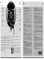
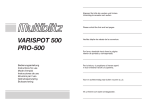
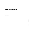
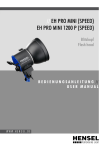
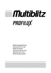
USER`S GUIDE D EN D XLite USER`S GUIDE USER`S GUIDE IR Empfänger/ Fotozelle Leistungsregler Display Leistungsanzeige, Anzeige Funkempänger “aktiv” & Anzeige “stand-by” und Aktivierung des Funkempfäners - das Gerät zum ersten mal in Betrieb genommen wird. - das Gerät 3 Monate nicht in Gebrauch war. Formierungsvorgang: 1. Gerät an das Netz anschließen und einschalten. Bitte entnehmen sie Informationen zur richtigen Handhabung des MURAS T Funkauslösers der entsprechenden Bedienungsanleitung. 2. D ie Leistung in Abständen von 15 Min. über die fünf Blenden (1.0 -5.0) erhöhen. 3. Gerät während der Formierung nicht „abblitzen”!!! Halogen An/Aus (An = Proportional) 4. Gerät in diesem Zustand 1 Stunde eingeschaltet lassen. Programmierung der Empfangskanäle: Im Gerät ist ein 16 Kanal Funkempfänger fest eingebaut, Sender/Funkauslöser und der im Gerät integrierte Empfänger müssen auf denselben Kanal eingestellt werden. Mit folgender Tastenkombination kann der Funkempfänger aktiviert und auf den gewünschten Empfangskanal eingestellt werden: Halogenlicht 100% An/Aus 2. Inbetriebnahme Nehmen sie die Schutzkappe vom Gerät ab indem sie das ReflektorSchloss an der Unterseite des Geräts in Richtung des Bedienungs-Panels schieben, dann die Schutzkappe gegen den Uhrzeigersinn drehen und herausnehmen. LED´s Anzeige Funktion An/Aus & “Stand-By” Gerät An/Aus Akkustische-/ optische Abblitzkontrolle Synchronbuchse Netzsteckdose/ Sicherungslade/ Ersatzsicherung Vielen Dank das sie sich für MULTIBLITZ entschieden haben, wir hoffen das ihnen die Arbeit mit diesem hochwertigen Qualitätsprodukt Freude bereiten wird. MULTIBLITZ Blitzgeräte werden ohne Ausnahme in Deutschland konstruiert und hergestellt. WICHTIGE HINWEISE ZUR PFLEGE UND INSTANDHALTUNG! Lesen Sie diese Bedienungsanleitung genau durch bevor sie dieses Produkt anwenden. Die Blitz-/ und Halogenröhren sowie Metallreflektoren werden im Betrieb sehr warm und können bei nicht sachgerechter Handhabung Verbrennungen verursachen. Das Öffnen des Gerätes könnte lebensgefährlich sein! Öffnen sie das Gerät unter keinen Umständen selber! Der Service sollte nur von einer autorisierten MULTIBLITZ Vertragswerkstatt durchgeführt werden. Decken Sie nicht die Ventilationsschlitze ab. 2 5. Funk-Synchronisation Die Blitzauslösung des Geräts kann über einen Funkauslöser (Code: MURAS T, separat erhältlich) erfolgen. Hierbei wird der Funkauslöser auf den Blitzschuh der Kamera aufgesteckt. Das Gerät/die Geräte blitzt/blitzen dann synchron beim Auslösen der Kamera ab. IR Empfänger/ Fotozelle An/Aus und Kanalwahl für Funkempfänger Test 1. Formierung der Blitzkondensatoren Die Blitzkondensatoren müssen unbedingt formiert werden wenn, Setzen Sie niemals Filter, Diffusionsmaterial oder ähnliches direkt auf die Blitz-/ oder Halogenröhre. Das Gerät darf auf keinen Fall Wasser, auch nicht Spritz- oder Tropfwasser, ausgesetzt werden. Das Gerät darf nicht mit ungeregelten Benzin- oder Dieselgeneratoren betrieben werden. Bei ständigem Gebrauch sollte das Gerät einmal jährlich in einer autorisierten MULTIBLITZ Vertragswerkstatt überprüft werden. Zur Vermeidung einer möglichen Beeinträchtigung der Umwelt oder der menschlichen Gesundheit darf dieses Produkt nicht in den Hausmüll gegeben werden, um zu gewährleisten, dass es in einer umweltverträglichen Weise recycelt wird. Wenden Sie sich für Informationen zu Entsorgungseinrichtungen an die zuständige Behörde oder das Geschäft, in dem Sie dieses Produkt erworben haben. ach 1 Stunde sind die Blitzkondensatoren formiert und das Gerät N kann in Gebrauch genommen werden. Halogenröhre Setzen sie die mitgelieferte Halogenröhre in das Gerät ein, siehe 7. “Wechseln der Halogen- und Blitzröhre”. Netzanschluß Das Gerät ist von Werk aus für den Betrieb an einem Stromnetz von 220-240 V/50-60 Hz Wechselspannung vorgesehen. Vor dem Anschluss an das Stromnetz ist sicherzustellen, dass die Netzspannung und die Angaben auf dem Typenschild übereinstimmen. Verbinden sie das Gerät über das mitgelieferte Netzkabel mit einer Steckdose, der mittlere Dezimalpunkt des Displays leuchtet und das Gerät befindet sich im „stand-by” Modus. Gerät mit dem Schalter „I-0“ einschalten. 3.Synchronisation über Kabel Das mitgelieferte Synchronkabel (Code: MASYG) in die Synchronbuchse einstecken und mit der Kamera verbinden. Beim Einsatz mehrerer Geräte genügt der Anschluss eines Gerätes, alle anderen lösen verzögerungsfrei über den eingebauten IR Empfänger/die Fotozelle aus. Hierbei müssen die IR Empfänger/die Fotozellen aller genutzten Geräte aktiv sein. 4. Optische-Synchronisation 1. Das Gerät kann auch ohne Synchronkabel durch einen IR Fernauslöser (Code: MUSEN, separat erhältlich) ausgelöst werden. Hierbei wird der Fernauslöser auf den Blitzschuh der Kamera aufgesteckt, der IR-Empfänger/die Fotozelle des Geräts muss über die entsprechende Taste angeschaltet werden. Das Gerät blitzt dann synchron beim Auslösen der Kamera ab. Beim Einsatz mehrerer Geräte müssen die IR-Empfänger/ die Fotozellen aller genutzten Geräte aktiv sein. - Die „Test“ Taste ca. 3 sek. gedrückt halten (ggf. gibt das Gerät ein akustisches Signal ab, abhängig davon ob die akustische oder optische Abblitzkontrolle aktiv ist), das Gerät blitzt einmal ab, das Symbol für die Kanalanwahl „CH“ erscheint auf dem Display, jetzt muss die Taste wieder losgelassen werden. - Nach ca. 2 sek. wechselt das Display mit einem kurzen akustischen Signal von „CH“ nach „--“ (= Funkempfänger nicht aktiv, kein Kanal eingestellt), da ab Werk kein Empfangskanal eingestellt und der Empfänger nicht aktiv ist. - Durch Drehen des Leistungsreglers kann jetzt der gewünschte Empfangskanal (z. Bsp. „12“ = Kanal 12) eingestellt werden. Die Anwahl des Kanals durch Drücken der „Test“ Taste bestätigen, das Display wechselt wieder zur Leistungsanzeige. - Der Funkempfänger ist jetzt aktiv und arbeitet nun auf dem angewählten Empfangskanal. Wechseln zwischen Empfangskanälen: - Die „Test“ Taste ca. 3 sek. gedrückt halten (ggf. gibt das Gerät ein akustisches Signal ab, abhängig davon ob die akustische oder optische Abblitzkontrolle aktiv ist), das Gerät blitzt einmal ab, das Symbol für die Kanalanwahl „CH“ erscheint auf dem Display, jetzt muss die Taste wieder losgelassen werden. - Nach ca. 2 sek. wechselt das Display mit einem kurzen akustischen Signal von „CH“ auf den eingestellten Kanal (z.Bsp. „07“ = Kanal 7), durch Drehen des Leistungsreglers kann jetzt ein anderer Empfangskanal (z.Bsp. „15“ = Kanal 15) eingestellt werden. Die Anwahl des Kanals durch Drücken der „Test“ Taste bestätigen, das Display wechselt wieder zur Leistungsanzeige. - Der Funkempfänger ist weiterhin aktiv und arbeitet nun auf dem neu angewählten Empfangskanal. 3 D XLite Technische Daten USER`S GUIDE XLite USER`S GUIDE 6. Wechseln der Lichtformer Lichtformer in das Bajonett einsetzen und mit Drehung im Uhrzeigersinn zum Einrasten bringen. Lösen in umgekehrter Reihenfolge. Reflexschirme sind nur mit dem Schutz- und Schirmreflektor (PLUSCH) verwendbar. Die Halterung für Reflexschirme ist in den Schutz- und Schirmreflektor integriert. 7. Wechseln der Halogen- und Blitzröhre Gerät durch gleichzeitiges Drücken von Taste „I-0“ und „TEST“ aus schalten und „abblitzen”. Dann den Netzstecker ziehen. Blitzt das Gerät nicht ab, mind. 45 min. warten damit der Blitzkondensator entladen wird und so ein gefahrloses Arbeiten an der Blitzröhre möglich ist. Lichtformer vom Gerät entfernen. Halogenröhre nach links losdrehen und nach vorne herausnehmen. Neue Halogenröhre nach rechts eindrehen. Herstellerinstruktionen in der Verpackung beachten. Blitzröhre am Glasrohr (die Elektroden nicht berühren) nach vorne herausziehen. Neue Röhre vorsichtig einsetzen, dabei muss die Zündklammer das Glasrohr der Blitzröhre umfassen und Kontakt zum Zünddraht haben. allerdings nur unter extremen Umständen erreicht, z. B. bei Umgebungs temperaturen von über 40°C mit gleichzeitiger, direkter Langzeitsonneneinstrahlung und hoher Blitz-Anzahl. Bei gängigem Studiogebrauch wird eine Überhitzung des Gerätes nicht eintreten. 9. Sicherungen Zum Wechseln der Sicherungen, Gerät ausschalten und vom Netz trennen. Einen kleinen Schraubendreher hinter dem oberen Teil der Sicherungslade ansetzen und diese nach vorne herausdrücken. Die Gerätesicherung befindet sich im hinteren Teil, die Ersatzsicherung im vorderen Teil der Sicherungslade. Defekte Sicherung ausschließlich durch gleichwertige Sicherung ersetzen: 220 - 240 V = T 4 A 8. Automatische Temperaturüberwachung Das Gerät ist mit einer Temperaturüberwachung ausgerüstet die den Blitz und das Halogenlicht ausschaltet sobald eine Temperatur von ca. 50°C im inneren des Gerätes überschritten wird. Nachdem das Gerät abgekühlt ist gibt die Temperaturüberwachung Blitz- und Halogenlicht wieder automatisch für den Gebrauch frei. Temperaturen von ca. 50°C werden XLite 500 + BLITZENERGIE, Ws: 500 + NETZSPANNUNG, V: 220 - 240 + LEITZAHl, 1 m, ISO 100, Reflektor RINOS 2/50°: 64,0 + Blende, 1 m, ISO 100, Reflektor RINOS 2/50°: 64,0 + VARIATIONSBEREICH, Blenden / Ws (Regelbar in 1/10 Stufen): 5/ 31,25-500 + BLITZFOLGE, sek: P 1/16 = 0,5, P 1/1 = 1,7 + Blitzdauer t 0.5, sek: P 1/16=1/500, P 1/1=1/1000 + HALOGEN EINSTELL-LICHT, W / Sockel / Code: 205 / B 15d / LUHAL 3 + gewicht, kg 2,6 + FARBTEMPERATUR (bei max. Leistung), °K: 5500 +/- 150° + SYNCHRONKABEL-SPANNUNG, V: <5 + BLITZSPANNUNGSSTABILITÄT: +/- 0,5 % + BLITZRÖHRE, UV gesperrt, Code: XROW / XROR + BLITZAUSLÖSUNG:FOTOZELLE, SYNCHRONKABEL, HANDAUSLÖSER (TEST), INFRAROT, FUNK (MIT RS 2 FUNKAUSLÖSER) + ANSCHLUSSWERTE: 230 V / 4 A / 0,92 kVA + ELEKTRISCHE SICHERHEIT: DIN IEC 491, VDE 0882 + ABMESSUNGEN: 363 x 146 x 146 mm Toleranzen der technischen Daten für Meßwerte und Bauelemente nach DIN- und IEC Norm. Technische Änderungen vorbehalten. XLite FAQ Warum funktioniert die Auslösung des Geräts mit einem Synchronkabel nicht? Überprüfen Sie ob das Kabel richtig in den Buchsen des Geräts/ihrer Kamera eingesteckt ist. Warum funktioniert die Auslösung des Geräts mit meinem RS2 Funkauslöser nicht? Überprüfen sie ob der Empfangskanal des Geräts mit dem Sendekanal des Funkauslösers übereinstimmt und ob der Funkempfänger im Gerät aktiviert ist. Siehe Seite 3, Punkt 5. Warum blitzt das Gerät manchmal ab wenn ich in kurzen Zeitabständen die Leistung herunterregle? Das Gerät muss jedes mal sobald es heruntergeregelt wird überschüssige Energie abbauen, dies geschieht durch Abblitzen. Kann ich mein/e XLite Gerät/e an einem Multiblitz PROPAC 1 oder PROPAC 2 Akku betreiben? Nein, die Geräte dürfen nicht an den PROPAC Akkus betrieben werden. Warum funktioniert die Auslösung des Geräts mit meinem MUSEN Infrarot-Auslöser nicht? Überprüfen sie ob der Schalter “IR Empfänger/Fotozelle An-Aus” aktiviert ist. Warum erwärmt sich die hintere Oberseite des Gehäuses im „stand-by“ Modus leicht? Auf dieser Seite ist das Netzteil des Geräts verbaut. Systembedingt wird es im „stand-by“ Modus handwarm. 4 5 EN XLite USER`S GUIDE USER`S GUIDE IR receiver/ Slave cell Output Setting Display Output, wireless receiver “active” and “stand-by” indication IR receiver /Slave Cell On-Off Radio trigger channel selection LED´s Test button Function On-Off indication Activates radio trigger 1. Formation of flash capacitors Formation of the flash capacitors is absolutely but only necessary when, Formation Process: 1. Connect the supplied mains cable to a power outlet and power up the unit. 2. I ncrease the energy output in 15 min. intervals over the five f-stop range (1.0 - 5.0). 3. Do NOT fire any flashes during the formation process!!! 4. Leave the unit set to full energy (1/1) for about one hour. Power On-Off Beep/Lamp Ready indicator Modeling Lamp On (prop x)-Off Modeling Lamp 100% On-Off Sync Socket Power socket/ Fuse box/Spare fuse the unit is put into operation for the first time or was not in use for more than 3 months. F ormation of the flash capacitor is completed after one hour and the unit is ready for use. 2. Putting into operation To remove the protection cap unlock the reflector lock on the bottom side of the unit by pushing it away from the protection cap. Remove the protection cap by turning it counter-clockwise and taking it out. Place the supplied halogen tube into the unit, see “7. Changing halogenand flash tubes”. The unit is factory-set to 220-240 V / 50-60 Hz AC voltage. Before making any connection make sure that the mains voltage match the indications on the type label on the bottom of the unit. Thank you for choosing MULTIBLITZ, we hope you enjoy working with this high quality product. MULTIBLITZ flash units are without exception designed and manufactured in Germany. Do not place filters, diffusing materials, or any other obstructions directly onto the flash-/ and halogen tubes. Do not expose the unit to water, nor spray-/or dripping water. IMPORTANT CARE & MAINTENANCE INFORMATION! Please read the instruction manual carefully before using this product. Flash-/ and halogen tubes as well as metal parts can become very warm during operation and may cause burns if not handled properly. Opening the unit could be extremely dangerous! Do not open the unit by yourself! Service should only be executed by an authorized MULTIBLITZ service location. Do not obstruct the venting slots. Do not run the unit with unregulated gasoline-/or diesel generators. When permanently in use, this unit should be serviced once a year by an authorized MULTIBLITZ service location. The crossed out wheeled bin label that can be found on your product indicates that this product should not be disposed of via the normal household waste stream. To prevent possible harm to the environment or human health please separate this product from other waste streams to ensure that it can be recycled in an environmentally sound manner. For more details on available collection facilities please contact your local government office or the retailer where you purchased this product. 6 Connect the unit to a wall outlet using the supplied power cable. Now, the mid decimal point on the units´ display lights up indicating stand-by mode. Press the „I-0“ button to power up the unit. 3.Synchronisation with a sync cable Plug the supplied sync cable (Code: MASYG) into the units’ sync terminal and connect it to your camera. In a multi-flash set-up the sync cable only needs to be connected to the master-unit, all other slave-units will fire without delay, triggered by their built-in IR receiver/Slave Cell. Remember to activate the IR receiver/Slave Cell on each slave-unit. 4. Optical Synchronisation The unit may be fired using an Infrared Remote Trigger (Code: MUSEN, sold separately). Attach the IR remote trigger to your cameras’ flash shoe. The flash units´ IR receiver/Slave Cell must be activated by pressing the corresponding button. The unit will fire synchronously with the camera when it is being triggered. In a multi-flash set-up, the IR receiver/Slave Cell must be activated on each unit. 5. Synchronisation with a radio trigger The unit/s may be fired using a radio trigger (Code: MURAS T, sold separately). The radio trigger (transmitter) has to be attached to the cameras’ flash shoe, when the camera is triggered the unit/s will fire synchronously. For detailed information on the MURAS T radio trigger please refer to the corresponding user manual. Selecting the receiving channel: The unit is equipped with a 16-channel wireless receiver. Transmitter (MURAS T) and receiver must be set to the same channel. The receiver can be activated and set to the desired receiving channel with the following key sequences: - Press and hold the “TEST” button for approx. 3 sec. (the unit might emit a beep depending on the selected flash monitor setting: “beep” or “lamp ready”), the unit fires once and the symbol for the channel selection “CH” appears on the display, now let go of the button. - After approx. 2 sec. the unit emits a beep and the symbol on the display changes from „CH” to „--“, meaning that the receiver is not activated and no channel is selected (factory setting). - The desired receiving channel can now be set by turning the output control, e.g. to “12“ (channel 12). Confirm the selection of the channel by pressing the “Test“ button, the previously selected output reappears on the display. - The wireless receiver is now active and acts on the selected channel, the blinking of the second decimal point on the units´ display indicates the activity of the receiver. Changing the receiving channel: - P ress and hold the “TEST” button for approx. 3 sec. (the unit might emit a beep depending on the selected flash monitor setting: “beep” or “lamp ready”), the unit fires once and the symbol for the channel selection “CH” appears on the display, now let go of the button. - After approx. 2 sec. the unit emits a beep and the symbol on the display changes from „CH” to the previously selected channel, e.g. to “07“ (channel 7). The desired receiving channel can now be set by turning the output control, e.g. to “15“ (channel 15). Confirm the selection of the channel by pressing the “TEST“ button, the previously selected output reappears on the display. - The wireless receiver is now active and acts on the selected channel, the blinking of the second decimal point on the units´ display indicates the activity of the receiver. 7 EN XLite Technical Data USER`S GUIDE XLite USER`S GUIDE 6.Changing light shapers All Multiblitz light shapers have a bayonet mount and can be locked in the units´ bayonet. Unlock the reflector lock on the bottom side of the unit by pushing it towards the control panel, insert the desired light shaper in the mount, and turn clockwise to lock. To remove a light shaper, proceed in the reverse order. Use umbrellas exclusively with the PLUSCH umbrella reflector, which includes the umbrella holder. 7.Changing the halogen- and flash tubes Switch off the unit by pressing and holding the „I-0“ button while firing a flash by pressing the „TEST“ button, then let go of the „I-0“ button. Pull the mains cable. Should the unit fail to fire, wait for at least 45 minutes to make sure that the capacitor is fully discharged and the flash tube can be touched without any risk. Remove the light shaper from the unit (see “6. Changing light shapers“). Gently push the halogen tube inwards, turn it counterclockwise and pull it out of its socket. Put in the new halogen tube and secure it by turning it clockwise (Follow the manufacturer’s instructions). Pull out the flash tube by gripping it by its glass. (Watch out for hot parts and be sure not to touch the electrodes!) Carefully insert the new tube. The firing clamp should embrace the glass and be in contact with the triggering wire. are only being reached under extreme circumstances like direct, long-term solar radiation together with an extremely high flash count and very brief flash repetitions. The unit will not overheat when used in a usual studio set-up. 9. Fuses To change fuses, switch the unit off and pull the power plug. Fuse box: Push the fuse box out towards the front with the aid of small screwdriver placed behind the upper part of the box. The fuse is located at the rear, a spare fuse at the front of the box. Always replace the blown fuse by one with an identical rating: 220 - 240 V = T 4 A 8.Automatic Temperature Control The unit is equipped with a temperature control which switches off the flashand the halogen light as soon as the units’ inside temperature rises over approx. 50° C. When the unit has cooled-off, all functions are being switched on automatically by the temperature control, again. However, temperatures of over 50° C XLite 500 + FLASH POWER, Ws:500 + Power supply, V: 220 - 240 + Guide number, 1 m, ISO 100, Reflector RINOS 2/50°: 64.0 + F-stop, 1 m, ISO 100, Reflector RINOS 2/50°: 64.0 + Control range, F-stops / Ws (adjustable in 1/10 power increments): 5/ 31,25-500 + Recycling time, sec: P 1/16 = 0.5, P 1/1 = 1.7 + Flash duration t 0.5, sec: P 1/16=1/500, P 1/1=1/1000 + Halogen modelling light, W / socket / code: 205 / B 15d / LUHAL 3 + Weight, kg 2.6 + COLOUR TEMPERATURE (at max. output), °K: 5500 +/- 150° + Sync socket, V: <5 + Flash voltage stability: +/- 0.5 % + Flash tube, UV absorbing, code: XROW / XROR + Flash triggering:SLAVE cell, sync cable, open flash button (TEST), infra-red, radio (WITH RS 2 RADIO TRIGGER) + Connected load: 230 V / 4 A / 0.92 kVA + Electric safety: DIN IEC 491, VDE 0882 + Dimensions: 363 x 146 x 146 mm Tolerances of the technical data for measured values and components according to the standard DIN IEC // Subject to technical changes XLite FAQ Why does the unit not fire when I try to sync it to my camera using a sync lead? Check if the sync lead is properly connected to the sync socket of the unit and to your camera. Why does the unit sometimes fire when I turn down the output control to often in a short period of time? The unit has to dissipate excess energy every time the output control is being turned down. Why does the unit not fire when I try to sync it to my camera using the RS 2 radio trigger? Check if a receiving channel of the wireless receiver is active, see page 3 point 5 and if the RS 2 trigger is properly connected to your camera. Can I run my XLite unit/s on a Multiblitz PROPAC 1 or PROPAC 2 battery pack? No, the XLite must not be run on a PROPAC 1 or PROPAC 2 battery pack. Why does the unit not fire when I try to sync it to my camera using the MUSEN infrared trigger? Check if the “IR/Slave Cell On-Off” button is switched on, see page 3 point 4 and if the infrared trigger is properly connected to your camera. Why does the housing above the control panel heats up a bit during stand-by? The top side of the unit is where the power supply sits. Determined by the system it gets warm to the touch during stand-by mode. 8 9 Image by: Meike Heckeler Multiblitz-Info D Ihr neues, hochwertiges MULTIBLITZ-Gerät wurde auf dem Weg zu Ihnen durch eine Spezialverpackung geschützt. Bitte heben Sie die Verpackung für spätere Transportzwecke auf. Blitz-Holgenröhre und Schutzglas bei Rücktransport nicht im Gerät lassen. bitte separat verpacken. EN Your new and valuable MULTIBLITZ unit has been send to you in special protective packing for maximum protection. We suggest that this packing material be kept for later use. Before shipment, be sure to remove flash, and halogen tubes as well as pyrex protection glasses from the unit. Please pack separately. 10 11 Visit us online: www.multiblitz.de Scope of Delivery xlite 5 Halogen TUbe Unit 1 x halogen tube 205 W Code: LUHAL 3 1 x Xlite 500 with protection cap LUKAP Code: XLite 5 Cable FLASH TUBE 1 x power cable, 5 m Code: VANET 1 x sync lead Code: MASYG D/EN 01.12 1 x flash tube Code: XROW MULTIBLITZ Dr. Ing. D. A. Mannesmann GMBH | Ferdinand - Porsche - StrASSE 19 | D-51149 KÖLN | GERMANY | Fon: +49 (0) 2203 - 93 96 10 | Fax: +49 (0) 2203 - 93 96 49 e-mail: [email protected] | internet: www.multiblitz.de