1
Instrucciones de servicio / Operating Instructions
Edición/Edition: AG
simovert
masterdrives
Motion Control
Onduladores (CC-CA) Forma constructiva Kompakt PLUS
Frequency Inverter (DC-AC) Compact PLUS Type
06.2005
Generalidades
Indice
1
DEFINICIONES Y PRECAUCIONES............................................................... 1-1
2
DESCRIPCIÓN................................................................................................. 2-1
3
TRANSPORTE, ALMACENAMIENTO, DESEMBALAJE............................... 3-1
4
PRIMERA PUESTA EN SERVICIO ................................................................. 4-1
5
MONTAJE ........................................................................................................ 5-1
5.1
Montaje del equipo ........................................................................................... 5-1
5.2
5.2.1
5.2.2
Montaje de tarjetas opcionales......................................................................... 5-4
Montaje de tarjetas opcionales para equipos con anchura de hasta 90 mm ... 5-4
Montaje de tarjetas opcionales para equipos con anchuras de
135 mm y 180 mm ............................................................................................ 5-7
6
MONTAJE ADECUADO A LA CEM................................................................ 6-1
7
CONEXIÓN....................................................................................................... 7-1
7.1
7.1.1
7.1.2
Terminales de potencia .................................................................................... 7-5
Conexiones de potencia para equipos con anchura de hasta 90 mm ............. 7-6
Conexiones de potencia para equipos con anchuras de 135 mm y 180 mm .. 7-7
7.2
Conexiones de mando...................................................................................... 7-8
7.3
Sección de conductores ................................................................................. 7-18
7.4
Combinaciones de equipos ............................................................................ 7-18
8
PARAMETRIZACIÓN....................................................................................... 8-1
8.1
Menú de parámetros......................................................................................... 8-1
8.2
Entrada de parámetros vía PMU ...................................................................... 8-5
8.3
Entrada de parámetros vía OP1S .................................................................... 8-8
Siemens AG
6SE7087-8KP50
SIMOVERT MASTERDRIVES
Instrucciones de servicio
0-1
Generalidades
06.2005
8.4
8.4.1
8.4.1.1
8.4.1.2
8.4.2
8.4.2.1
8.4.2.2
8.4.2.3
8.4.3
8.4.3.1
8.4.3.2
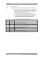
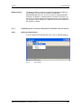
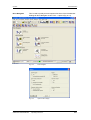
Entrada de parámetros vía DriveMonitor........................................................ 8-12
Instalación y enlaces ...................................................................................... 8-12
Instalación....................................................................................................... 8-12
Conexión......................................................................................................... 8-12
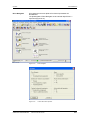
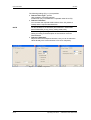
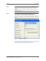
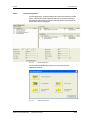
Establecimiento de la comunicación DriveMonitor – unidad .......................... 8-13
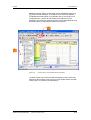
Ajustar interface USS ..................................................................................... 8-13
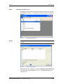
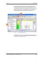
Arrancar con búsqueda en el bus USS .......................................................... 8-15
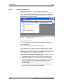
Creación de juegos de parámetros ................................................................ 8-16
Parametrización.............................................................................................. 8-18
Estructura de la lista de parámetros, parametrización vía DriveMonitor........ 8-18
Diagnóstico general ........................................................................................ 8-23
8.5
Reset de parámetros al ajuste de fábrica....................................................... 8-24
8.6
Parametrización vía download ....................................................................... 8-25
8.7
Parametrización con módulos de parámetros ................................................ 8-26
8.8
Lista de motores ............................................................................................. 8-39
8.9
Identificación de motor.................................................................................... 8-48
8.10
Parametrización completa .............................................................................. 8-48
9
MANTENIMIENTO ........................................................................................... 9-1
9.1
9.1.1
9.1.2
9.1.3
9.1.4
Cambio del ventilador ....................................................................................... 9-1
Cambio del ventilador para equipos de hasta 45 mm de ancho ...................... 9-2
Cambio del ventilador para equipos de hasta 90 mm de ancho ...................... 9-2
Cambio del ventilador en equipos con una anchura de 135 mm ..................... 9-2
Cambio del ventilador en equipos con una anchura de 180 mm ..................... 9-3
10
FORMAR ........................................................................................................ 10-1
11
DATOS TÉCNICOS........................................................................................ 11-1
12
FALLOS Y ALARMAS ................................................................................... 12-1
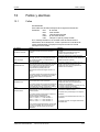
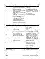
12.1
Fallos .............................................................................................................. 12-1
12.2
Alarmas......................................................................................................... 12-14
12.3
Fallos fatales (FF)......................................................................................... 12-39
13
COMPATIBILIDAD MEDIOAMBIENTAL ...................................................... 13-1
0-2
Instrucciones de servicio
6SE7087-8KP50 Siemens AG
SIMOVERT MASTERDRIVES
03.2005
1
Definiciones y precauciones
Definiciones y precauciones
Personal cualificado
En el sentido en que aparece en la documentación o en las señales de
precaución marcadas en el producto mismo, son aquellas personas
familiarizadas con la instalación, montaje, puesta en marcha,
funcionamiento y mantenimiento del producto y que disponen de las
calificaciones acordes a su actividad, p. ej.:
♦ Formación, instrucción o autorización para conectar y desconectar,
poner a tierra y marcar circuitos y aparatos de acuerdo a las normas
de seguridad.
♦ Formación o instrucción de acuerdo a las normas de seguridad para
la conservación y uso del equipo de seguridad adecuado.
♦ Formación en primeros auxilios.
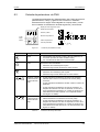
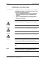
PELIGRO
Este símbolo indica que el no respeto de las medidas de seguridad
correspondientes causa la muerte, lesiones corporales graves o daños
materiales importantes.
ADVERTENCIA
Este símbolo indica que el no respeto de las medidas de seguridad
correspondientes puede causar la muerte, lesiones corporales graves
o daños materiales importantes.
PRECAUCIÓN
Este símbolo (con triángulo de señalización) indica que el no respeto
de las medidas de seguridad correspondientes puede causar lesiones
corporales.
PRECAUCIÓN
Este símbolo (sin triángulo de señalización) indica que el no respeto de
las medidas de seguridad correspondientes puede causar daños
materiales.
ATENCIÓN
Este símbolo indica que el no respeto de las medidas de seguridad
correspondientes puede causar un resultado o estado no deseado.
INDICACION
En el sentido que indica la documentación, se trata de una información
importante sobre el producto o sobre una parte de la documentación
hacia la que se quiere llamar especialmente la atención.
Siemens AG
6SE7087-8KP50
SIMOVERT MASTERDRIVES
Instrucciones de servicio
1-1
Definiciones y precauciones
PRECAUCION
03.2005
Durante el funcionamiento de los equipos eléctricos hay determinadas
partes de los mismos que están sometidas forzosamente a tensión
peligrosa.
Si no se observan las indicaciones de precaución pueden producirse
graves lesiones o daños materiales considerables.
Solo deberá trabajar en este equipo personal adecuadamente
cualificado.
Dicho personal tiene que estar perfectamente familiarizado con todas
las consignas de seguridad y con las medidas de mantenimiento
especificadas en esta documentación.
El perfecto y seguro funcionamiento de este equipo presupone un
transporte correcto, un almacenamiento, montaje e instalación
adecuados así como un uso y un mantenimiento cuidadosos.
INDICACION
Por motivos de claridad expositiva, está documentación no detalla
todas las informaciones referentes a las variantes completas del
producto, ni se pueden considerar todos los casos posibles de
instalación, servicio o mantenimiento.
Si precisa informaciones complementarias o surgen problemas
específicos no tratados con el suficiente detalle en esta
documentación, póngase en contacto con la delegación o agencia de
SIEMENS más próxima, donde recibirá la información adecuada.
También queremos hacer notar que el contenido de esta
documentación no forma parte de un convenio, promesa o relación
jurídica pasada o en vigor, o que la deba modificar. El contrato de
compra es el único documento que especifica las obligaciones de
Siemens, y además el único que incluye la reglamentación válida sobre
garantías. Lo expuesto en esta documentación ni amplía ni limita las
estipulaciones de garantía fijadas.
1-2
Instrucciones de servicio
6SE7087-8KP50 Siemens AG
SIMOVERT MASTERDRIVES
03.2005
Definiciones y precauciones
Dispositivos sensibles a las cargas electrostáticas (ESD)
ATENCION
El presente equipo contiene componentes sensibles a las cargas
electrostáticas. Estos dispositivos pueden destruirse fácilmente si no se
manipulan con los cuidados debidos. Si, a pesar de todo, necesita
trabajar con las tarjetas electrónicas, observe las siguientes
instrucciones:
Las tarjetas electrónicas solo deberán tocarse cuando sea inevitable
porque se tenga que trabajar en ellas.
Si a pesar de ello es necesario tocar las tarjetas, inmediatamente antes
de hacerlo es necesario descargar el propio cuerpo.
Las tarjetas no deberán entrar nunca en contacto con sustancias
altamente aislantes, p. ej. piezas sintéticas, placas de mesa aislantes,
ropa de fibras sintéticas.
Las tarjetas solo deberán depositarse sobre bases conductoras.
Las tarjetas y los componentes solo deberán guardarse o enviarse en
embalajes conductores (p. ej. cajas de plástico metalizadas o cajas de
metal).
Si el embalaje no es conductor, entonces antes de su embalado las
tarjetas deberán envolverse con un material conductor. Para ello puede
utilizarse p. ej. gomaespuma conductora o lámina de aluminio de uso
doméstico.
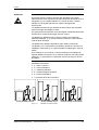
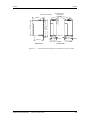
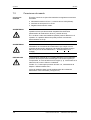
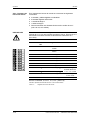
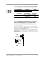
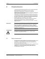
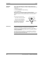
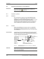
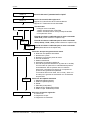
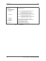
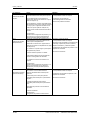
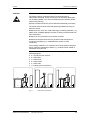
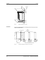
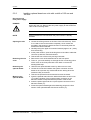
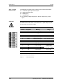
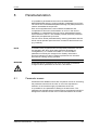
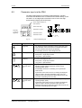
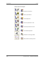
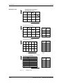
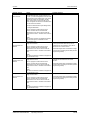
La figura siguiente resume de nuevo las medidas de protección
antiestática necesarias.
♦ a = suelo conductor
♦ b = mesa antiestática
♦ c = calzado antiestático
♦ d = ropa de trabajo antiestática
♦ e = pulsera antiestática
♦ f = puesta a tierra de los armarios
d
d
b
b
d
e
e
f
a
c
f
f
c
Puesto de trabajo sentado
Figura 1-1
a
Puesto de trabajo de pie
f
f
c
a
Puesto de trabajo de pie/sentado
Medidas de protección ESD
Siemens AG
6SE7087-8KP50
SIMOVERT MASTERDRIVES
Instrucciones de servicio
1-3
Definiciones y precauciones
03.2005
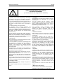
Indicaciones de seguridad y aplicación sobre
convertidores de corriente para accionamientos
(según: Normas para baja tensión 73/23/EWG)
1. Generalidades
Los convertidores para accionamientos pueden tener, en
función de su grado de protección, piezas bajo tensión,
desnudas, posiblemente movibles o en movimiento, así
como superficies a alta temperatura.
Si la cubierta requerida se retira de forma no
reglamentaria, si los convertidores son empleados
inadecuadamente o si la instalación y el servicio son
deficientes, pueden producirse graves lesiones y daños
materiales.
Para
más
información,
correspondiente.
v.
la
documentación
Todos los trabajos de transporte, instalación y puesta en
marcha han de ser realizados por personal
especializado y cualificado (observar IEC 60364 y
CENELEC HD 384 ó DIN VDE 0100 e IEC 60664 ó DIN
VDE0110 y las normas vigentes nacionales para la
prevención de accidentes).
Personal cualificado en el sentido de estas consignas
fundamentales de seguridad son aquellas personas
encargadas de la instalación, montaje, puesta en
marcha y servicio del producto, que disponen de las
suficientes calificaciones para cumplir con sus
cometidos.
2. Utilización conforme
Los
convertidores
para
accionamientos
son
componentes para incorporar en instalaciones o
máquinas eléctricas.
Cuando se montan en máquinas está prohibida la
puesta en marcha del convertidor para accionamientos
(es decir, el comienzo del servicio previsto) hasta tanto
se haya comprobado que la máquina cumple con todas
las determinaciones de la Directiva de la UE 98/37/EG
(Directiva sobre maquinaria); observar la norma EN
60204.
La puesta en marcha (es decir el comienzo del servicio
previsto) solamente es admisible si se cumple la
Directiva EMC sobre compatibilidad electromagnética
(89/336/CEE).
Los convertidores para accionamientos cumplen con la
Directiva de baja tensión 73/23/CEE. Las normas armonizadas de la serie EN 50178 / DIN VDE 0160 junto con
EN 60439-1/ DIN VDE 0660 parte 500 y EN 60146 /
VDE 0558 son aplicables a los convertidores para
accionamientos.
En la placa de características y en la documentación
están indicados los datos técnicos y las condiciones
para la conexión, que se han de cumplir sin falta.
3. Transporte, almacenamiento
Deberán observarse las indicaciones respecto al
transporte, almacenamiento y manejo adecuados.
Observar las condiciones ambientales especificadas en
EN 50178.
1-4
4. Instalación
La instalación y refrigeración de los equipos deben
cumplir con las determinaciones especificadas en la
documentación correspondiente.
Proteger los convertidores para accionamientos contra
cargas inadmisibles. Es especialmente importante que
durante el transporte y manejo no se doblen
componentes ni se cambien las distancias de
aislamiento de los módulos o tarjetas. Evitar el contacto
con módulos, tarjetas y contactos electrónicos.
Los convertidores para accionamientos incorporan
módulos y tarjetas sensibles a las cargas electrostáticas
que se dañan fácilmente cuando el manejo es
inadecuado. Los componentes eléctricos no deben
dañarse ni destruirse mecánicamente (¡podría hasta
peligrar la salud!).
5. Conexión eléctrica
Observar las determinaciones nacionales vigentes para
la prevención de accidentes cuando se trabaja con
convertidores para accionamientos bajo tensión (p. ej.
BGV A2).
La instalación eléctrica se efectuará de acuerdo con las
normas aplicables (p. ej. sección de los conductores,
fusibles, conexión al conductor de protección). En la
documentación figuran indicaciones complementarias.
La documentación de los convertidores para
accionamientos incluye indicaciones para la instalación
conforme respecto a la compatibilidad electromagnética:
apantallamiento, puesta a tierra, disposición de los filtros
y tendido de los conductores. Estas indicaciones se
observarán también en los convertidores para
accionamientos que llevan la marca Œ. El fabricante de
la instalación o máquina responde del cumplimiento de
los valores límite exigidos por la Directiva EMC.
6. Servicio
En caso dado deberán incorporarse dispositivos
adicionales de vigilancia y protección en las
instalaciones con convertidor para accionamiento, con
objeto de cumplir las normas de protección vigentes en
cada caso, p. ej. prescripciones sobre material técnico,
de seguridad, etc. Se permite modificar los ajustes del
convertidor para accionamientos usando el software de
manejo.
Después
de
seccionar
el
convertidor
para
accionamientos de la tensión de alimentación, no tocar
las partes del mismo, los terminales sometidos a
tensión, ni las conexiones de potencia, ya que
posiblemente aún están cargados los condensadores.
Observar las correspondientes placas de indicación en
el convertidor para accionamientos.
Mantener cerradas todas las cubiertas y puertas durante
el servicio.
7. Mantenimiento y reparaciones
Observar la documentación del fabricante.
¡Guardar estas consignas de seguridad!
Instrucciones de servicio
6SE7087-8KP50 Siemens AG
SIMOVERT MASTERDRIVES
03.2005
2
Campo de
aplicación
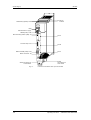
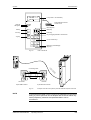
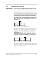
Descripción
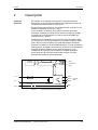
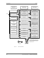
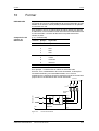
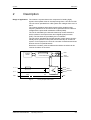
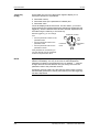
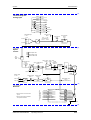
Descripción
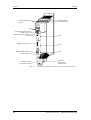
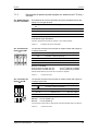
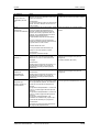
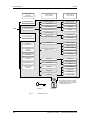
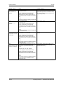
El ondulador es un aparato de la electrónica de potencia para la
alimentación de accionamientos trifásicos de alta dinámica dentro de
una gama de potencias de 0,75 kW a 37 kW.
El aparato se puede conectar a una red de corriente continua con una
tensión comprendida entre 510 V y 650 V.
Con el ondulador se produce, de la tensión continua del circuito
intermedio, mediante la modulación de duración de impulsos (PWM),
un sistema de corriente trifásica con una frecuencia de salida que
oscila entre 0 Hz y 400 Hz.
La electrónica de regulación se encarga del control del aparato. Esta
se compone de un microprocesador y un procesador analógico digital
(DSP), las funciones se realizan por medio del software del equipo.
El manejo se realiza con el panel PMU del equipo, el panel de mandos
opcional OP1S, el regletero de bornes o a través de un sistema de bus.
Para esto el aparato dispone de una serie de interfaces y tres
receptáculos de conexión para el empleo de tarjetas opcionales.
Como tacos para el motor se pueden utilizar resolver, encoder,
generador de impulsos y taco multivueltas.
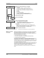
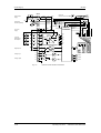
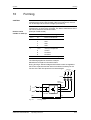
Tarjetas
opcionales
Regleter.bornes
PMU
Electrónica de regulación
Interface en
serie
U2/T1
C / L+
V2/T2
W2/T3
D/LFusible circuito
intermedio
Circuito
intermedio
Conexión
motor
Ondulador
PE2
PE3
Figura 2-1
Esquema de principio del ondulador
Siemens AG
6SE7087-8KP50
SIMOVERT MASTERDRIVES
Instrucciones de servicio
2-1
03.2005
3
Transporte, almacenamiento, desembalaje
Transporte, almacenamiento,
desembalaje
Transporte
Almacenamiento
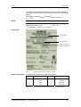
Los equipos y los componentes se embalan en fábrica de acuerdo al
pedido recibido. Por fuera, en el embalaje, se encuentra un cartel
indicativo. Atienda a las instrucciones del mismo referentes al
transporte, almacenamiento y uso adecuado del equipo.
Evite someter al equipo durante el transporte a vibraciones fuertes.
Evite también someterlo a golpes fuertes. En el caso de detectar daños
por traslado, rogamos que lo notifique a la agencia de transportes.
Los equipos y los componentes deben ser almacenados en lugares
secos y limpios. Se permiten temperaturas comprendidas entre -25 °C
(-13 °F) y +70 °C (158 °F). Las fluctuaciones de temperatura no
deberán sobrepasar los 30 K por hora.
PRECAUCIÓN
Cuando el tiempo de almacenamiento sobrepasa dos años, se tiene
que volver a formar el equipo. Véase el capítulo ”Formar”.
Desembalaje
El embalaje consta de cartón normal y cartón ondulado. El material se
puede eliminar o gestionar de acuerdo a las normas locales para este
tipo de productos. Tras desembalar el producto y controlar la integridad
del envío y el estado intacto del equipo y de los componentes, puede
comenzarse el montaje y la instalación del mismo.
Siemens AG
6SE7087-8KP50
SIMOVERT MASTERDRIVES
Instrucciones de servicio
3-1
03.2005
4
Primera puesta en servicio
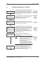
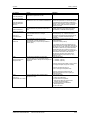
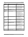
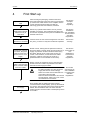
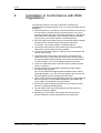
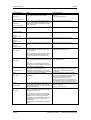
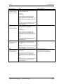
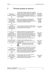
Primera puesta en servicio
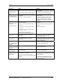
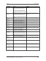
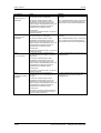
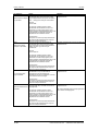
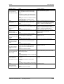
Desembalaje y
control de los equipos
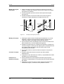
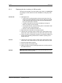
Tras desembalar el equipo asegúrese de la integridad
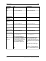
del mismo. Solo se deben poner en servicio equipos en Véase capítulo
"Transporte,
estado intacto. Controle si el equipo está completo, si la
almacenamiento,
dotación de las tarjetas opcionales es correcta y en
caso de haberlo pedido asegúrese del desbloqueo de la desembalaje"
opción tecnológica.
Montaje del aparato
y de las tarjetas
opcionales que no
están ya montadas
Monte, en caso necesario, las tarjetas opcionales. Monte
el aparato atendiendo a las indicaciones referentes a la
compatibilidad electromagnética (CEM) y a las
condiciones del lugar de instalación.
Véase capítulo
"Montaje"
y "Montaje
adecuado
a la CEM"
En caso
necesario formar los
condensadores del
circuito intermedio
Si el circuito intermedio del aparato ha estado más de
dos años sin tensión, se tienen que formar de nuevo los
condensadores del circuito intermedio.
Véase capítulo
"Formar"
Empalme el
conductor protector, el
cable de potencia o el
embarrado y, si hay, la
alimentación externa de
24 V
Empalmar (comenzando con el conductor protector) el
cable de potencia o el embarrado del circuito intermedio
Véase capítulo
y la alimentación externa de 24 V. Tenga en cuenta al
"Montaje" y
tender el cable las indicaciones referentes a la CEM. No
"Montaje
conecte todavía ningún cable para: control,
adecuado a la
comunicación, taco y motor (excepción: cable para la
CEM"
conexión de un OP1S si la parametrización se lleva a
cabo a través del OP1S).
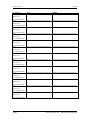
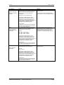
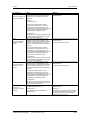
Conexión de cables:
mando, comunicación,
taco y motor
Conecte los restantes cables para: control,
comunicación, taco y motor. Observe al tenderlos las
indicaciones CEM.
ADVERTENCIA Antes de conectar o desconectar los
Véase capítulo
cables de mando y el cable del captador
"Conexión" y
se tiene que desconectar el aparato libre
"Montaje
de tensión (alimentación de la
adecuado a la
electrónica de 24 V y tensiones de red y
CEM"
del circuito intermedio)
Si no se lleva a cabo esta medida se
pueden producir defectos en el captador.
Un captador defectuoso puede producir
movimientos descontrolados en el eje.
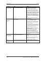
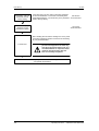
Conecte la
alimentación externa
de 24 V
Después de controlar el cableado para ver si está fijo y
las conexiones bien hechas, conecte la alimentación
externa de 24 V. Después de ponerse en
funcionamiento la electrónica se inicializa el aparato.
Este proceso puede tardar varios segundos. Al final se
visualiza el estado del aparato en la PMU.
Siemens AG
6SE7087-8KP50
SIMOVERT MASTERDRIVES
Instrucciones de servicio
111
4-1
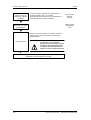
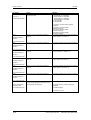
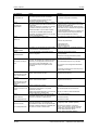
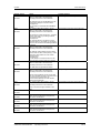
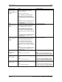
Primera puesta en servicio
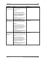
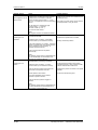
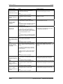
Si es necesario,
realice un reset de
parámetros al ajuste
de fábrica
03.2005
Cuando el aparato, después de la inicialización no
muestra el estado °005, o ya se había
parametrizado anteriormente, se aconseja realizar un
reset de parámetros al ajuste de fábrica.
Parametrización por
"Download" o módulos
de parámetros
Véase capítulo
"Parametrización"
Véase capítulo
"Parametrización"
Vuelva a controlar el aparato y los cables, conecte la
tensión de red y haga una prueba funcional según
parametrización.
Prueba funcional
ADVERTENCIA Asegúrese que al conectar la tensión
y el aparato no se produzcan
peligros para las personas o para la
instalación. Se recomienda acoplar
la máquina operadora después de
acabar con éxito la prueba funcional.
Proseguir puesta en servicio y parametrización
atendiendo a las prescripciones concretas
4-2
Instrucciones de servicio
6SE7087-8KP50 Siemens AG
SIMOVERT MASTERDRIVES
03.2005
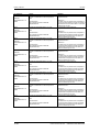
Montaje
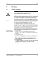
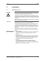
5
Montaje
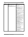
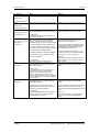
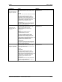
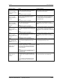
5.1
Montaje del equipo
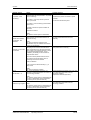
ADVERTENCIA
Un funcionamiento seguro del equipo presupone el que haya sido
montado y puesto en servicio por personal cualificado considerando las
precauciones enunciadas en estas instrucciones.
En particular es necesario observar tanto los reglamentos de
instalación y seguridad generales y nacionales para trabajos en
instalaciones de alta intensidad (p. ej. VDE, UL) como los referentes al
uso correcto de herramientas y dispositivos de seguridad personal.
De no observarse las indicaciones de precaución puede producirse la
muerte, lesiones corporales graves o daños materiales considerables.
Espacios
Condiciones del
lugar de instalación
Para el montaje deberá tomarse en cuenta que las terminales de
conexión del circuito intermedio se encuentran en la parte superior y
las destinadas al motor en la parte inferior del equipo.
Los aparatos se deberán montar adosados (uno junto al otro).
Para garantizar que el equipo obtenga una refrigeración suficiente hay
que dejar un espacio de 100 mm, tanto en la parte superior como en la
inferior, entre el equipo y los otros componentes que puedan interferir
notoriamente en la circulación del aire de refrigeración.
Si se monta el equipo dentro de un armario se tiene que dimensionar el
sistema de refrigeración del mismo de acuerdo a la energía que se
pierde. La información al respecto se encuentra en los datos técnicos.
♦ Cuerpos extraños
El equipo debe ser protegido de la penetración de cuerpos
extraños, en caso contrario no se garantiza el funcionamiento ni la
seguridad.
♦ Polvo, gases, vapores
Los lugares de instalación deben de estar secos y desprovistos de
polvo. El aire suministrado no debe contener partículas de polvo,
gases o vapores conductores de electricidad o que pongan en
peligro el funcionamiento. En caso necesario deberán instalarse los
filtros correspondientes o tomar otras medidas de precaución.
♦ Aire de refrigeración
Los equipos solo deben funcionar bajo condiciones ambientales que
se ajusten a la norma DIN IEC 721-3-3 clase 3K3. Si las
temperaturas del aire de refrigeración sobrepasan los 45 °C
(113 °F) y/o las instalaciones se encuentran a una altitud superior a
1000 m sobre el nivel del mar, resulta imprescindible reducir el
rendimiento.
Siemens AG
6SE7087-8KP50
SIMOVERT MASTERDRIVES
Instrucciones de servicio
5-1
Montaje
03.2005
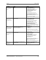
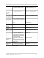
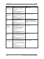
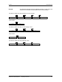
100 mm
Superficie de
montaje
Figura 5-1
Montaje
100 mm
Aire de refrigeración
Espacios mínimos para la refrigeración
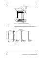
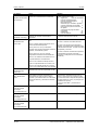
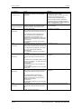
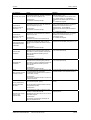
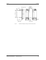
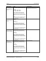
El montaje del equipo se realiza directamente sobre la superficie de
montaje. Para su fijación se precisan dos o cuatro tornillos M5.
Superficie de montaje
Escotaduras para
tornillos M5
414 mm
425 mm
360 mm
260 mm
22,5 mm
45 mm
33,75 mm
67,5 mm
45 mm
90 mm
220 mm
0,55 kW
Vista lateral
4,0 kW
Vista frontal (sin tapa)
Figura 5-2
5-2
1,5 / 2,2 kW
Croquis acotado para equipos con una anchura de hasta 90 mm
Instrucciones de servicio
6SE7087-8KP50 Siemens AG
SIMOVERT MASTERDRIVES
03.2005
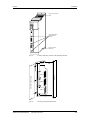
Montaje
Superficie de montaje
Escotaduras para
tornillos M5
414 mm
425 mm
360 mm
25 mm
260 mm
22,5 mm
135 mm
180 mm
220 mm
5,5 / 7,5 / 11 kW
Vista lateral
Figura 5-3
15 - 37 kW
Vista frontal
Croquis acotados para equipos con anchuras de 135 mm y 180 mm
Siemens AG
6SE7087-8KP50
SIMOVERT MASTERDRIVES
Instrucciones de servicio
5-3
Montaje
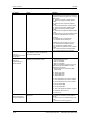
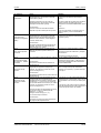
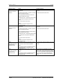
5.2
03.2005
Montaje de tarjetas opcionales
PELIGRO
5.2.1
Debido a la carga remanente de los condensadores del circuito
intermedio, el equipo mantiene tensiones peligrosas hasta 5 minutos
después de la desconexión. Por tanto no está permitido trabajar en el
aparato o en los bornes del circuito intermedio hasta transcurrido dicho
tiempo de espera.
Montaje de tarjetas opcionales para equipos con anchura de hasta
90 mm
Desconectar el
aparato de la red
PELIGRO
Quitarle la toma de tensión a la unidad de alimentación o al convertidor
y dejar el aparato desconectado de la corriente. Quite la fuente de
tensión de 24 V para la electrónica. Aparte todas las líneas de
alimentación.
Desmontaje del
equipo
Desmonte el equipo de la siguiente forma:
♦ Abra los bornes del embarrado del circuito intermedio.
♦ Quite los tornillos de fijación que sujetan el equipo a la superficie de
montaje.
♦ Tire del equipo hacia abajo hasta que quede totalmente libre el
embarrado del circuito intermedio.
♦ Tire del equipo hacia delante.
♦ Coloque el equipo sobre la parte izquierda.
♦ Afloje los dos tornillos de fijación del lateral derecho. Los tornillos se
encuentran el la parte superior, en el ángulo interior derecho y en la
parte inferior, en el centro del lateral derecho del aparato.
♦ No es necesario quitar los tornillos completamente, en el lateral se
encuentra una escotadura que permite inclinar la tapa al aflojar los
tornillos.
♦ Abra la parte lateral derecha. Para hacerlo inclínela hacia delante y
tire de ella hacia arriba hasta sacarla de las guías de posición que
se encuentran en el borde delantero.
♦ Retire de la placa frontal la tapa del slot elegido.
♦ Para eso tiene que separar cuidadosamente con un cuchillo
delgado los cuatro puntos que unen la tapa con la placa frontal.
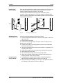
Apertura del equipo
Destapar el slot
5-4
Instrucciones de servicio
6SE7087-8KP50 Siemens AG
SIMOVERT MASTERDRIVES
03.2005
Montaje
Tornillos de fijación
tapa lateral
SIEMENS
A
S1
X101
Placa de
denominación de las
tarjetas opcionales
B
X103 C
Tornillos de fijación
tapa lateral
Figura 5-4
Posición de los tornillos de sujeción en el lateral derecho
PBI
Lateral derecho abierto
Slot A
Slot B
Parte posterior
CU
Slot C
Figura 5-5
Quitar el lateral derecho
Siemens AG
6SE7087-8KP50
SIMOVERT MASTERDRIVES
Instrucciones de servicio
5-5
Montaje
03.2005
Montaje de tarjetas
opcionales
Deslice la tarjeta opcional por detrás en la abertura de la placa frontal
(c), hasta que coincida el enchufe de 64 polos en la tarjeta principal
con el conector de la tarjeta opcional.
Conecte la tarjeta opcional por la derecha al enchufe de 64 polos de la
tarjeta principal (d). (la derecha se refiere a la parte derecha del
aparato cuando este está montado).
Atornille la tarjeta con los dos tornillos a los puntos de fijación situados
en la parte delantera de la tarjeta (e).
Slot C
c
e
Parte posterior
Parte posterior
Slot B
Slot C
d
e
Figura 5-6
Armar y montar el
equipo
Montaje de las tarjetas opcionales
Cierre la pared lateral derecha del equipo:
♦ Introduzca la pared lateral derecha por arriba, en el conducto
situado en la parte delantera del lateral derecho.
♦ Incline el lateral hacia atrás.
♦ Fije de nuevo el lateral con los dos tornillos.
Montaje del equipo:
♦ Deslice el equipo desde adelante, debajo del embarrado del circuito
intermedio, a su lugar de instalación.
♦ Suba el equipo hacia arriba hasta que el embarrado del circuito
intermedio quede completamente dentro del empalme.
♦ Fije el equipo con los tornillos de sujeción a la superficie de
montaje.
♦ Atranque el embarrado del circuito intermedio.
♦ Empalme todas las líneas de alimentación que había quitado
anteriormente.
Identificar las
tarjetas opcionales
5-6
♦ Asegúrese de que las líneas de alimentación y los apantallamientos
estén ajustados y en correcta posición.
♦ Para la identificación de las tarjetas opcionales ponga la placa
indicadora correspondiente en el lugar previsto de la parte delantera
del equipo.
♦ Después de conectar la tensión puede registrar las tarjetas en el
software del equipo y comenzar con la puesta en servicio.
Instrucciones de servicio
6SE7087-8KP50 Siemens AG
SIMOVERT MASTERDRIVES
03.2005
5.2.2
Montaje
Montaje de tarjetas opcionales para equipos con anchuras de
135 mm y 180 mm
Desconectar el
aparato de la red
PELIGRO
Quitarle la toma de tensión a la unidad de alimentación o al convertidor
y dejar el aparato desconectado de la corriente. Quite la fuente de
tensión de 24 V para la electrónica. Aparte todas las líneas de
alimentación.
INDICACION
Montar las tarjetas opcionales una vez montada la parte de potencia.
Apertura del equipo
♦ Afloje los dos tornillos de fijación de la parte frontal del equipo.
Estos se encuentran en la parte superior. No es necesario quitar los
tornillos completamente, en la carcasa se encuentran escotaduras
que permiten quitar la parte frontal cuando los tornillos han sido
aflojados.
♦ Incline con cuidado, un poco (aproximadamente 30 °) la parte
frontal hacia adelante y sáquela de la carcasa.
♦ En la parte de potencia, abra las patillas de enganche del cable
plano que establece la conexión con la electrónica de control.
♦ Saque la parte frontal del equipo hacia adelante.
♦ Retire de la placa frontal la tapa del slot elegido.
♦ Para eso tiene que separar cuidadosamente con un cuchillo
delgado los cuatro puntos que unen la tapa del slot con la placa
frontal o bien quitar la tapa ciega.
♦ Primero afloje los dos tornillos de la tarjeta opcional
aproximadamente en una vuelta.
♦ Afloje la unión del conector a la platina electrónica para que no se
produzcan tensiones mecánicas en la tarjeta al seguir aflojando los
tornillos.
♦ Afloje completamente los tornillos de la tarjeta opcional y sáquela.
Destapar el slot
Quitar las tarjetas
opcionales
Siemens AG
6SE7087-8KP50
SIMOVERT MASTERDRIVES
Instrucciones de servicio
5-7
Montaje
Montaje de tarjetas
opcionales
03.2005
♦ Deslice la tarjeta opcional por detrás en la abertura de la placa
frontal (c), hasta que coincida el enchufe de 64 polos en la tarjeta
principal con el conector.
♦ Conecte la tarjeta opcional al enchufe de 64 polos de la tarjeta
principal (d).
♦ Atornille la tarjeta con los dos tornillos a los puntos de fijación
situados en la parte delantera de la tarjeta opcional (e).
e
Slot C
Slot C
d
c
e
Figura 5-7
Montaje del equipo
Conectar el equipo
Identificar las
tarjetas opcionales
5-8
Montaje de las tarjetas opcionales
♦ Mantenga la parte frontal inclinada (aproximadamente 30 °) hacia
adelante y enganche (acercándose por abajo) la muesca de la
chapa guía inferior en la regleta de la parte de potencia.
♦ Fije el conector macho del cable de unión al conector hembra de la
parte de potencia y cierre las patillas de enganche.
♦ Enderece la parte frontal con cuidado hacia adelante y métala en la
carcasa. Tenga en cuenta que las chapas guías en la parte derecha
de la parte frontal del aparato (visto de frente) calcen en las
escotaduras de la carcasa.
♦ Fije la parte frontal con los dos tornillos de sujeción a la parte de
potencia.
♦ Empalme todas las líneas de conexión que había quitado
anteriormente
♦ Asegúrese de que las líneas de conexión y el apantallamiento estén
ajustados y en correcta posición.
♦ Para la identificación de las tarjetas opcionales ponga la placa
indicadora correspondiente en el lugar previsto de la parte delantera
del equipo.
♦ Después de conectar la tensión puede registrar las tarjetas en el
software del equipo y comenzar con la puesta en servicio.
Instrucciones de servicio
6SE7087-8KP50 Siemens AG
SIMOVERT MASTERDRIVES
03.2005
6
Montaje adecuado a la CEM
Montaje adecuado a la CEM
Seguidamente se da un resumen de informaciones y directrices
básicas que le facilitarán el cumplimiento de los normas referentes a la
compatibilidad electromagnética (CEM) y al reglamento de la CE.
♦ Asegúrese de que el contacto entre la carcasa del convertidor o del
ondulador y la superficie de montaje sea conductora. Se
recomienda el uso de superficies de montaje que conduzcan bien la
electricidad (p. ej. planchas de acero con un baño de cinc). Si la
superficie de montaje está aislada (p. ej. por una capa de pintura)
utilice arandelas de contacto o con púas.
♦ Todas las piezas metálicas del armario tienen que estar bien unidas
unas con otras de tal forma que conduzcan bien la electricidad. En
caso necesario utilice arandelas de contacto o con púas.
♦ Utilice cintas de conexión lo más cortas posible para unir las
puertas del armario.
♦ Utilice cables apantallados para conectar el ondulador con el motor.
♦ La pantalla de los cables de conexión del motor tiene que estar
conectada a la pantalla del ondulador y de forma amplia a la placa
de montaje del motor. Si las caja de bornes del motor fueran de
plástico se deberán utilizar conductores flexibles adicionales para la
puesta a tierra.
♦ No se debe interrumpir el apantallamiento de los cables del motor
con bobinas de salida, fusibles o contactores.
♦ Apantalle todos los conductores de señales. Separe los
conductores de señales en grupos de señales.
No ponga conductores para señales digitales no apantallados al
lado de conductores para señales analógicas. Si utiliza solamente
un cable, tiene que estar cada señal apantallada por separado.
♦ Los cables de energía y de señalización tienen que ser colocados a
una distancia mínima de 20 cm uno del otro. Utilice láminas
separadoras entre ambos. Las láminas deberán ser puestas a
tierra.
♦ Ponga a tierra los conductores de reserva por los dos extremos.
Con ello logra una efectividad de apantallamiento adicional.
♦ Tienda los cables lo más junto posible a láminas que ya están
puestas a tierra. Con esto disminuye la influencia de señales
parásitas.
♦ Evite longitudes de cable innecesarias. A través de ellas se
producen capacitancias e inductancias de acoplamiento
adicionales.
Siemens AG
6SE7087-8KP50
SIMOVERT MASTERDRIVES
Instrucciones de servicio
6-1
Montaje adecuado a la CEM
03.2005
♦ Utilice cables con pantalla de hilos trenzados. Cables con pantalla
de lámina son cinco veces peores en su apantallamiento.
♦ Las bobinas excitadoras del contactor que estén conectadas a la
misma red que el convertidor o que se encuentren en su cercanía,
tienen que ser conectadas a limitadores de sobretensión (p. ej.
módulos RC o varistores)
En el compendio encontrará mayores informaciones. En el capítulo 3
"Indicaciones de instalación para montaje de accionamientos
adecuado a la compatibilidad electromagnética (CEM)".
El compendio se encuentra en el CD incluido en el suministro y
también se puede pedir en forma impresa
(referencia: 6SE7087-8QX70).
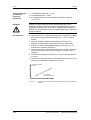
PRECAUCIÓN
Este producto es de categoría restringida según IEC 61800-3 y solo se
puede utilizar en redes públicas si se toman las medidas adicionales
correspondientes.
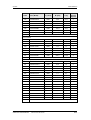
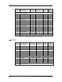
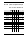
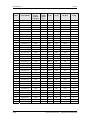
INDICACION
Según la normativa EMC para accionamientos de velocidad variable
EN 61800-3:1996 + A11:2000 capítulo 6.3.2.3 b, los sistemas de
accionamiento (PDS = Power Drive Systems) deben de cumplir con los
límites establecidos en las tablas 11 y 12.
Existen aplicaciones donde, por motivos técnicos, no le es posible al
sistema PDS cumplir con estos limites. Se trata de las siguientes:
♦ Redes IT en sistemas de carácter complejo
♦ En lugares donde, el comportamiento funcional dinámico requerido,
se encuentra limitado debido al efecto ocasionado por el uso de
filtros.
Esta indicación se debe especialmente considerar en la opción L20
(funcionamiento con red sin puesta a tierra).
6-2
Instrucciones de servicio
6SE7087-8KP50 Siemens AG
SIMOVERT MASTERDRIVES
06.2005
7
PELIGRO
Conexión
Conexión
Los equipos SIMOVERT MASTERDRIVES trabajan con tensiones
elevadas.
¡Todos los trabajos de conexión deben realizarse en estado ”sin
tensión”!
Cualquier trabajo en el equipo debe ser realizado por personal
cualificado.
De no observarse las indicaciones preventivas, puede producirse la
muerte, lesiones corporales graves o daños materiales considerables.
Debido a la carga remanente de los condensadores del circuito
intermedio, el equipo mantiene tensiones peligrosas hasta 5 minutos
después de la desconexión. Por tanto no está permitido trabajar en el
aparato o en los bornes del circuito intermedio hasta transcurrido dicho
tiempo de espera.
Aunque esté parado el motor, en los bornes de potencia y en los
bornes de mando, puede haber aplicada tensión peligrosa.
Cuando la alimentación de la tensión del circuito intermedio sea
central, hay que asegurarse que el convertidor esté desconectado de la
tensión del circuito intermedio.
En caso de efectuar trabajos en el equipo abierto es necesario tener en
cuenta que quedan partes accesibles sometidas a tensión.
El usuario es responsable de que los equipos se instalen y conecten de
acuerdo a los reglamentos técnicos reconocidos en el país de la
instalación, así como otros reglamentos de validez regional. Esto
incluye particularmente al dimensionado de los cables, los dispositivos
de protección, la puesta a tierra, el sistema de desconexión, el sistema
de seccionamiento y la protección de sobrecorriente.
Siemens AG
6SE7087-8KP50
SIMOVERT MASTERDRIVES
Instrucciones de servicio
7-1
Conexión
06.2005
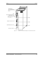
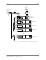
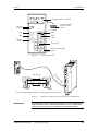
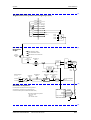
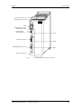
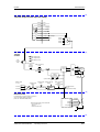
PE3
X533 PARADA segura
(opción)
+
−
X3 Embarrado del
circuito intermedio
SIEMENS
PMU
Alimentación externa CC24 V,
RS485 (USS) X100
X100
A
S1
Resistencia de terminación de bus
(USS) S1
Slot A
X101
B
Regletero de bornes X101
Slot B
X103 C
RS232 / RS485 (USS) X103
Slot C
Conexión motor X2
Soporte de pantalla
para cables de mando
Figura 7-1
7-2
Soporte de
pantalla para
cables de motor
Esquema de conexiones de equipos con una anchura de hasta 90 mm
Instrucciones de servicio
6SE7087-8KP50 Siemens AG
SIMOVERT MASTERDRIVES
06.2005
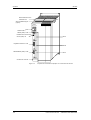
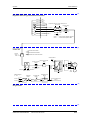
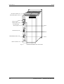
Conexión
Embarrado del
circuito intermedio X3
PE3
X533 PARADA segura
(opción)
+
−
SIEMENS
PMU
P
Alimentación externa CC24 V,
RS485 (USS) X100
A
Resistencia de terminación
de bus (USS) S1
S1
Slot A
X101 B
Regletero de bornes X101
Slot B
X103 C
RS232/RS485 (USS) X103
Slot C
Conexión al motor X2
Figura 7-2
Esquema de conexiones de equipos con una anchura de 135 mm
Siemens AG
6SE7087-8KP50
SIMOVERT MASTERDRIVES
Instrucciones de servicio
7-3
Conexión
06.2005
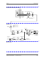
Embarrado del circuito
intermedio X3
PE3
X533 PARADA segura
(opción)
+
−
SIEMENS
PMU
P
Salida CC24 V,
RS485 (USS) X100
A
S1
Resistencia de terminación
de bus (USS) S1
Slot A
X101 B
Regletero de bornes X101
Slot B
X103 C
RS232/RS485 (USS) X103
Slot C
Conexión al motor X2
Figura 7-3
7-4
Esquema de conexiones de equipos con una anchura de 180 mm
Instrucciones de servicio
6SE7087-8KP50 Siemens AG
SIMOVERT MASTERDRIVES
06.2005
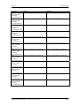
7.1
Conexión
Terminales de potencia
ADVERTENCIA
Conductor protector
El conductor protector tiene que ser conectado a la red y al motor.
Debido a las corrientes de fuga que fluyen por los condensadores
supresores de interferencias y según EN 50178:
• hay que usar una sección transversal mínima de 10 mm2 de Cu o
• si se utilizan conexiones a la red con secciones menores de
10 mm2 hay que conectar dos conductores protectores. La sección
de estos debe corresponder a la de los conductores externos.
INDICACION
Si el equipo está fijo a través de una buena unión conductora a una
superficie de montaje puesta a tierra, la sección del conductor protector
puede ser la misma que la del cable exterior. La superficie con puesta
a tierra cumple la función del segundo conductor protector.
Siemens AG
6SE7087-8KP50
SIMOVERT MASTERDRIVES
Instrucciones de servicio
7-5
Conexión
06.2005
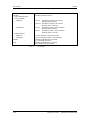
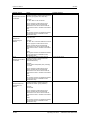
7.1.1
Conexiones de potencia para equipos con anchura de hasta
90 mm
Conductor protector
En la parte superior del equipo, detrás de la conexión del circuito
intermedio X3 se encuentra una conexión adicional, para un conductor
protector, en forma de un perno roscado M4.
Esta sirve para hacer la conexión de un conductor protector en el caso
de un montaje aislado.
X3 - Embarrado del
circuito intermedio
El embarrado del circuito intermedio sirve para el abastecimiento del
equipo con energía eléctrica.
Conductor
Denominación
Significado
Campo
3
PE3
Conexión conductor protector
2
D / L-
Ud-tensión -
CC 510 - 650 V
1
C / L+
Ud-tensión+
CC 510 - 650 V
Sección conectable: Barra ”cobre electrolítico estañado” 3x10 mm,
redondeado según DIN46433
Cuando el aparato está montado el conductor 1 se encuentra delante.
Tabla 7-1
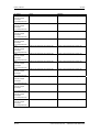
X2 - Conexión del
motor
Embarrado del circuito intermedio
La conexión del motor se encuentra en la parte inferior del equipo.
PE2 U2 V2 W2
Borne
Significado
Campo
PE2
Conexión conductor protector
U2
Fase U2 / T1
3 CA 0 V - 480 V
V2
Fase V2 / T2
3 CA 0 V - 480 V
W2
Fase W2 / T3
3 CA 0 V - 480 V
Sección conectable: 4 mm2 (AWG 10), multifilar
Cuando el aparato está montado el borne PE2 se encuentra delante.
Tabla 7-2
Conexión del motor
Para que la conexión del motor quede fija, se tiene que atornillar el
enchufe a la carcasa.
Los cables del motor se deben dimensionar de acuerdo con VDE 298
parte 2.
Después del montaje del enchufe, la pantalla del cable del motor se
debe fijar de forma amplia al soporte de pantalla.
7-6
Instrucciones de servicio
6SE7087-8KP50 Siemens AG
SIMOVERT MASTERDRIVES
06.2005
Conexión
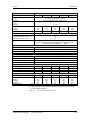
7.1.2
Conexiones de potencia para equipos con anchuras de 135 mm y
180 mm
X3 - Embarrado del
circuito intermedio
El embarrado del circuito intermedio sirve para el abastecimiento del
equipo con energía eléctrica.
Conductor
Denominación
Significado
Campo
3
PE3
Conexión conductor protector
2
D / L-
Ud-tensión -
CC 510 - 650 V
1
C / L+
Ud-tensión+
CC 510 - 650 V
Sección conectable: Barra ”cobre electrolítico estañado” 3x10 mm,
redondeado según DIN46433
Cuando el aparato está montado el conductor 1 se encuentra delante.
Tabla 7-3
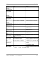
X2 - Conexión del
motor ≤ 18,5 kW
PE
U2
V2
Embarrado del circuito intermedio
La conexión del motor se encuentra en la parte inferior del equipo en
un bloque de bornes.
Borne
Significado
PE
Conexión conductor protector
U2 / T1
Fase U2 / T1
3CA 0 V - 480 V
V2 / T2
Fase V2 / T2
3CA 0 V - 480 V
W2 / T3
Fase W2 / T3
3CA 0 V - 480 V
W2
Sección conectable:
Anchura de la carcasa 135 mm:
Anchura de la carcasa 180 mm:
Campo
10 mm2 (AWG 8), multifilar
16 mm2 (AWG 6), multifilar
Viéndolo desde delante, el borne PE se encuentra a la izquierda.
Tabla 7-4
X2 – Conexión del
motor ≥ 22 kW
Conexión de motor
La conexión del motor se encuentra en la parte inferior del equipo en
un bloque de bornes.
Borne
U2
V2
W2
Significado
Campo
Conexión conductor protector
U2 / T1
Fase U2 / T1
3CA 0 V - 480 V
V2 / T2
Fase V2 / T2
3CA 0 V - 480 V
W2 / T3
Fase W2 / T3
3CA 0 V - 480 V
Sección conectable:
Máxima: 50 mm² (AWG 1/0),
Mínima: 10 mm² (AWG 6)
Los bornes PE se encuentran en la lámina de soporte de pantalla, abajo a la derecha.
Tabla 7-5
Conexión de motor
Siemens AG
6SE7087-8KP50
SIMOVERT MASTERDRIVES
Instrucciones de servicio
7-7
Conexión
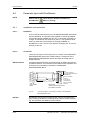
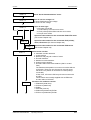
7.2
06.2005
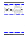
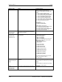
Conexiones de mando
Conexiones
estándar
El equipo consta en su ejecución básica de las siguientes conexiones
de mando:
♦ Alimentación externa CC 24 V, conexión de bus USS (RS485).
♦ Interface en serie para PC o OP1S.
♦ Regletero de bornes de mando.
ADVERTENCIA
Antes de conectar o desconectar los cables de mando y el cable del
captador se tiene que desconectar el aparato libre de tensión
(alimentación de la electrónica de 24 V y tensión de red).
Si no se lleva a cabo esta medida se pueden producir defectos en el
captador. Un captador defectuoso puede producir movimientos
descontrolados en el eje.
ADVERTENCIA
La alimentación externa de 24-V y todos los circuitos de intensidad
enlazados a las conexiones de mando tienen que cumplir con los
requisitos de protección referentes a la separación galvánica según
EN 50178 (circuito de intensidad PELV = Protective Extra Low
Voltage).
PRECAUCION
La alimentación externa de 24 V se debe asegurar con un interruptor
protector de línea para evitar sobrecargas en el circuito impreso y/o
componentes, en caso de defecto en el equipo, p. ej. cortocircuito en la
electrónica de control o fallo en el cableado.
Fusible –F1, F2 interruptor protector de línea 6 A, característica de
disparo C Siemens 5SX2 106-7.
(Sobre el cableado véase la hoja suplementaria de la unidad de
alimentación o del convertidor y la Figura 7-4).
7-8
Instrucciones de servicio
6SE7087-8KP50 Siemens AG
SIMOVERT MASTERDRIVES
06.2005
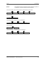
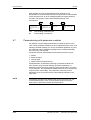
Conexión
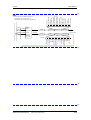
3 CA
380 - 480 V
Alimentación de
corriente
PELV
-F1
DC
24 V
-K1
-X9
2
1
U1 V1 W1
-X100
33
34
Electr.
control
Unidad de
alimentación
-X100
33
34
Electr.
control
Ondulador 1.1
-X100
33
34
Electr.
control
Ondulador 1.2
-X100
33
34
-F2
Electr.
control
Ondulador 1.3
-X100
33
34
Figura 7-4
Electr.
control
Ondulador 2.1
Accionamiento polimotórico con unidad de alimentación y ondulador
Siemens AG
6SE7087-8KP50
SIMOVERT MASTERDRIVES
Instrucciones de servicio
7-9
Conexión
06.2005
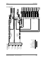
X100
33
PE
Interface en serie USS
(RS485)
Conmutador para
terminación de bus USS S1
P24
36 V
35
RS485P
TxD
RS485N
RxD
GND
RS485N
≥1
EN_RS232
Regulador
X101
1
P24
2
M24
Microcontrol
EN_RS485
Alimentación auxiliar
3
In
4
Entradas y
salidas digitales
bidireccionales
Out
Out/In
5V
In
5
6
9 8 7 6 5 4 3 2 1
Out
In
Out
In
4 entradas/salidas digitales bidireccionales
Salidas
7
5V
In
5V
In
24V
Entradas digitales
8
24V
Entradas
9
Entrada analógica
D
Figura 7-5
Slot A
Slot B
11
12
X103
A
10
7-10
Out
In
RS232 Id
BOOT
Out
In
24V
Salida analógica
+5V
RS485P
34
36
Out
ON
OFF
BOOT
RS485P
RS232 RxD
RS232 Id
- +
RS485N
RS232 TxD
P5V
24V
Alimentación
externa 24 V
D
A
Slot C
Esquema de conexiones estándar
Instrucciones de servicio
6SE7087-8KP50 Siemens AG
SIMOVERT MASTERDRIVES
06.2005
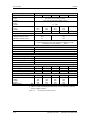
X100 - Alimentación
externa de CC24 V,
bus USS
33
34
35
36
Conexión
El regletero de bornes de cuatro polos sirve para conectar la
alimentación de tensión externa de 24 V (alimentación de la unidad de
alimentación o de un convertidor CA/CA), así como para conectar un
bus USS.
La conexión de bus USS se encuentra unida a la electrónica de mando
y al conector SUB D de nueve polos de la interface en serie X103.
La resistencia de terminación del bus se conectará si es necesario a
través del conector S1. En la posición inferior la resistencia de
terminación del bus está desconectada.
La conexión es necesaria si el aparato se encuentra en una de las
terminales del bus USS.
Borne
Denominación
Significado
Campo
33
+24 V (in)
Alimentación de tensión 24 V
CC 20-30 V
34
0V
Potencial de referencia
0V
35
RS485P (USS)
Conexión de bus USS
RS485
36
RS485N (USS)
Conexión de bus USS
RS485
Sección conectable: 2,5 mm2 (AWG 12)
Cuando el aparato está montado el borne 33 se encuentra arriba.
Tabla 7-6
alimentación externa de 24 V, bus USS
El aparato consume de la alimentación de tensión de 24 V una
cantidad de corriente de 1 A. El consumo aumenta a un máximo de
1,6 A cuando se incorporan tarjetas opcionales.
ATENCIÓN
La interface RS485 se puede operar en –X100 o –X103.
Siemens AG
6SE7087-8KP50
SIMOVERT MASTERDRIVES
Instrucciones de servicio
7-11
Conexión
06.2005
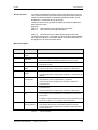
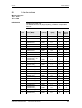
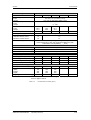
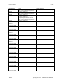
X101 - Regletero de
bornes de mando
En el regletero de bornes de mando se encuentran las siguientes
conexiones:
♦ 4 entradas y salidas digitales combinables
♦ 2 entradas digitales adicionales
♦ 1 entrada analógica
♦ 1 salida analógica
♦ Para las entradas una alimentación de tensión auxiliar de 24 V
(máx. 60 mA, solo salida!).
PRECAUCIÓN
Si se alimentan las entradas digitales con una fuente de tensión
externa de 24 V, hay que conectar la masa en X101.2. El borne X101.1
no se debe conectar a la fuente de alimentación externa de 24 V
(P24 AUX).
Borne
Denominación
Significado
Campo
1
P24 AUX
Alimentación de tensión
auxiliar
CC 24 V / 60 mA
2
M24 AUX
Potencial de referencia con
bobina
0V
3
DIO1
Entr./salida digital 1
24 V, 10 mA / 20 mA
4
DIO2
Entr./salida digital 2
24 V, 10 mA / 20 mA
5
DIO3
Entr./salida digital 3
24 V, 10 mA / 20 mA
6
DIO4
Entr./salida digital 4
24 V, 10 mA / 20 mA
7
DI5
Entrada digital 5
24 V, 10 mA
8
DI6
Entrada digital 6
24 V, 10 mA
9
AI−
Entrada analógica −
11 Bit + signo
Entrada diferencial:
10
AI+
Entrada analógica +
± 10 V / Ri = 40 kΩ
11
AO
Salida analógica
8 Bit + signo
± 10 V / 5 mA
12
M AO
Masa salida analógica
Sección conectable: 0,14 mm2 a 1,5 mm2 (AWG 16)
Cuando el aparato está montado el borne 1 se encuentra arriba.
Tabla 7-7
7-12
Regletero de bornes de mando
Instrucciones de servicio
6SE7087-8KP50 Siemens AG
SIMOVERT MASTERDRIVES
06.2005
Conexión
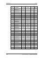
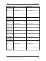
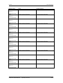
X103 - Interface en
serie
9
5
A través del conector SUB D de nueve polos se puede conectar de
forma opcional un OP1S o un PC con interface RS232 o RS485. Para
el PC existen diferentes cables de unión para los diferentes protocolos
de transmisión.
El conector SUB D de nueve polos está conectado internamente al bus
USS, de tal manera que se posibilita el intercambio de datos con otros
usuarios, que estén acoplados a través del bus USS.
Esta interface sirve también para cargar el Software.
Pin
Denominación
Significado
Campo
1
RS232 ID
Conmutación a protocolo RS232
Low activa
2
RS232 RxD
Datos de recepción a través de
RS232
RS232
3
RS485 P
Datos a través de la interface
RS485
RS485
4
Boot
Señal de mando para Update de
Software
Low activa
5
M5 AUX
Potencial de referencia para P5V
0V
6
P5V
Alimentación de tensión auxiliar
de 5 V
+5 V, máx. 200 mA
7
RS232 TxD
Datos de emisión a través de
RS232
RS232
8
RS485 N
Datos a través de la interface
RS485
RS485
9
M_RS232/485
Masa digital (con bobina)
6
1
Tabla 7-8
Interface en serie
Siemens AG
6SE7087-8KP50
SIMOVERT MASTERDRIVES
Instrucciones de servicio
7-13
Conexión
06.2005
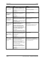
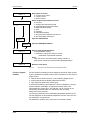
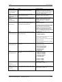
X533 - Opción
Parada segura
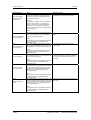
Con la opción "parada segura" se puede interrumpir el control de la
parte de potencia mediante un relé de seguridad. Asegurando así que
el aparato no genere ningún campo rotatorio en el motor.
Incluso aunque la electrónica de mando genere órdenes de excitación,
la parte de potencia no puede mover el motor.
La función "parada segura" es un "dispositivo para evitar un arranque
inesperado" según EN 60204-1, apartado 5.4 y cumple (con las
conexiones externas correspondientes) los requisitos de la categoría
de protección 3 según EN 954-1.
PELIGRO
La función "parada segura" no genera separación galvánica entre el
motor y la parte de potencia. Los bornes del motor se encuentran bajo
tensión peligrosa.
La opción "parada segura" no es adecuada para parar rápidamente un
motor en marcha, ya que al desconectar las señales de excitación el
motor solo se frena a través de la carga.
El motor no ejerce ningún par de giro cuando la función "parada
segura" está activada. Se necesitan dispositivos de bloqueo
adicionales (p. ej. frenos) si actúan fuerzas externas en los ejes
accionadores o si se trata de accionamientos sin retención automática
(p. ej. ejes con carga gravitatoria).
Queda un pequeño riesgo: En el caso de producirse dos fallos a la vez
en la parte de potencia. El accionamiento se puede alinear en un
pequeño ángulo de giro (motores asíncronos: en el margen de
remanencia, máx. 1 paso de ranuras, lo que correspondería a aprox.
de 5° a 15°).
INDICACION
Los productos aquí descritos han sido desarrollados para formar parte
de una instalación o de una máquina y cumplir con funciones
enfocadas a la seguridad. Un sistema completo con este enfoque
dispone, por lo general, de sensores, unidades de evaluación,
monitores, señalizadores y conceptos para desconexiones de
seguridad. Corre a cargo de la responsabilidad del fabricante el
garantizar el total y correcto funcionamiento de una instalación o
máquina. Siemens AG, sus sucursales y compañías asociadas (a
continuación solo "Siemens") no está en la capacidad de garantizar
todas las propiedades de una instalación o máquina que no haya sido
concebida por Siemens.
Siemens no se responsabiliza por las recomendaciones que se den o
se deduzcan de la siguiente descripción. En base a la presente
descripción no se puede derivar ningún tipo de garantía, ni
responsabilidades que vayan más allá de las condiciones de suministro
generales de Siemens.
7-14
Instrucciones de servicio
6SE7087-8KP50 Siemens AG
SIMOVERT MASTERDRIVES
06.2005
Conexión
La opción "parada segura" consta de un relé de seguridad, de bornes
de conexión para el control del relé y de un contacto de mensaje de
acuse.
X533
1
2
3
4
Borne
Denominación
Significado
Campo
1
Contacto 1
Mens. acuse "parada segura"
CC 20 V – 30 V
2
Contacto 2
Mens. acuse "parada segura"
1A
3
Entrada mando
"parada segura"
Resistencia nominal de la
bobina de excitación
≥ 823 Ω ± 10 % para 20 °C
4
P24 CC
Tensión de alimentación
"parada segura"
CC 20 V – 30 V
máx. régimen de
carga: 6/min
CC 24 V /
30 mA
Sección conectable: 1,5 mm2 (AWG 16)
Tabla 7-9
Asignación de bornes de la opción "parada segura"
La bobina de excitación del relé de seguridad está conectada por un
lado a la masa electrónica puesta a tierra. Si alimenta la bobina
mediante una tensión externa de 24 V, el polo negativo tiene que estar
conectado al potencial de tierra. Esta alimentación de 24 V debe
cumplir los requisitos para circuitos de intensidad PELV según EN
50178 (DIN VDE 0160).
En estado de suministro hay un puente entre los bornes 3 y 4. Para
utilizar la función "PARADA SEGURA" tiene que quitarlo y conectar un
mando externo para seleccionar la función.
Si abastece el relé de seguridad con la fuente de alimentación interna
X533:4, la externa de 24 V en el borne X9:1/2 debe suministrar por lo
menos 22 V para que el relé funcione con completa eficacia (caída de
tensión interna).
Regletero de bornes
- X533
1 2 3 4
P15
Alimentación
optoacoplador /
LWL
Siemens AG
6SE7087-8KP50
SIMOVERT MASTERDRIVES
Instrucciones de servicio
7-15
Conexión
06.2005
Los contactos de acuse de recibo del relé de seguridad contactan [con
la carga mencionada (30 V CC / 1 A)] como mínimo 100.000 veces. La
vida útil mecánica es de aprox.10 millones de ciclos interruptores. El
relé es un componente fundamental para la seguridad y el buen
funcionamiento de la máquina. Por ese motivo cuando se produzca
una disfunción se tiene que cambiar la placa con el relé. En este caso,
mandar el aparato a reparación o cambiarlo. Para detectar una
disfunción es necesario hacer pruebas funcionales regularmente. Los
periodos de tiempo que le pueden servir como directriz se encuentran
en la especificación de la mutua de previsión BGV A1 §39, apartado 3.
La prueba de funcionamiento se debe efectuar según sea la aplicación,
(al menos una vez al año) y además: al hacer la primera puesta en
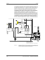
servicio y después de reparaciones, cambios, o reacondicionamientos.
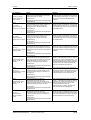
P24
Demanda liberación
sistema de protección
S2
Abierto
K2
-Y1
DES
emerg.
Cerrado
-S1
Red
K2
Contactor
principal
A1
Y10 Y11 Y12
Y21 Y22
13
23
31
47
57
A1
3TK2828
Y33 Y34
PE
A2
Y10 Y11 Y12
Y21 Y22
13
23
31
47
3TK2828
14
24
32
48
Y33 Y34
58
PE A2
-Q1
57
K1
14
24
32
48
58
Reset
S3
K1
X533
1
2
4
3
U1 V1 W1
Opción K80
P24
PV
M
X101
X
Y
-K1
DES3
n=0
Tarjeta
regulación
CU
-K2
DES1
SIMOVERT
MASTERDRIVES
U2 V2 W2
M
X: Entrada binaria, enlazar a DES3
p. ej. X101.8 --> P558 = 21
Y: Entrada binaria, enlazar a mensaje
"valor comparativo alcanzado"
p.ej. X101.6 --> P654 = 120; P796 = 0 (valor comparativo)
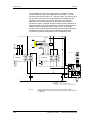
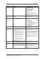
Figura 7-6
7-16
3
M
Ejemplo de aplicación de la función "parada segura" en combinación con
seguridad por contactor, para la supervisión de un sistema de protección
móvil en la categoría de seguridad 3 según EN 954-1
Instrucciones de servicio
6SE7087-8KP50 Siemens AG
SIMOVERT MASTERDRIVES
06.2005
Conexión
Todas los cables externos importantes para la seguridad deben estar
protegidos, p. ej. tendidos en canales para excluir cortocircuitos.
Observe las directrices para la técnica de tendidos en EN 60204-1,
apartado 14.
En el circuito de la Figura 7-6 el fiador o gacheta libera el sistema de
protección móvil una vez detenido el accionamiento. En casos
determinados y cuando el análisis de riesgo de la máquina lo permita
se puede prescindir de él. Entonces, el contacto normalmente cerrado
del sistema de protección, se conecta directamente a los bornes Y11 e
Y12 y el electroimán -Y1 deja de ser necesario.
La entrada binaria X esta enlazada con la orden "DES3" invertida, o
sea, con una señal de 24 V el convertidor detiene el motor, mediante la
rampa de deceleración parametrizada. El convertidor indica mediante
la salida binaria Y velocidad cero y con ello excita el relé K2.
Cuando se alcanza el reposo, se desconecta el relé en el convertidor y
mediante el contacto de acuse la bobina del contactor principal K1
permanece con 24 V. Si los contactos del relé de seguridad bloquean,
no cierran los contactos de acuse y la combinación de seguridad a la
derecha activa el contactor principal K1 mediante los contactos de
retardo 47/48 una vez pasado el tiempo de retardo ajustado.
Siemens AG
6SE7087-8KP50
SIMOVERT MASTERDRIVES
Instrucciones de servicio
7-17
Conexión
7.3
06.2005
Sección de conductores
Conductor protector
Si el equipo está fijo a través de una buena unión conductora a una
superficie de montaje puesta a tierra, la sección del conductor protector
puede ser la misma que la del cable de exterior.
ADVERTENCIA
Cuando los aparatos con una anchura de hasta 90 mm se monten
de forma aislada, hay que conectar un segundo conductor protector
(sección como la del cable exterior) a la conexión a tierra (perno
roscado M4 en la parte superior del aparato, al lado del borne de
conexión a la red).
Cable del motor
Sobre secciones y conductores véase el catálogo Motion Control
SIMOVERT MASTERDRIVES MC o bien IEC 60 204-1: 1997/1998.
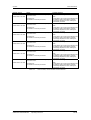
7.4
Combinaciones de equipos
Para instalaciones simples de accionamientos polimotóricos se pueden
alimentar del circuito intermedio de CC del convertidor Kompakt PLUS
(CA-CA) uno o varios onduladores de tipo Kompakt PLUS (CC/CA).
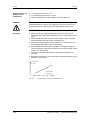
ADVERTENCIA
La suma de las potencias de accionamiento de los onduladores no
debe ser mayor que la potencia del convertidor. Para ello es válido un
factor de simultaneidad de 0,8.
Por ejemplo a un convertidor con una potencia de accionamiento de
5,5 kW se le pueden conectar, un ondulador con 4 kW y uno con
1,5 kW en una barra de CC común.
Los componentes de la red se establecen según la suma de potencias
de todos los convertidores y onduladores. Para un accionamiento
polimotórico con un convertidor de 5,5 kW, un ondulador de 4 kW y un
convertidor de 1,5 kW se tienen que seleccionar los componentes
correspondientes a un convertidor de 11 kW. Si la suma de potencias
no corresponde exactamente a la de un convertidor determinado, hay
que dimensionar los componentes de la red de acuerdo al convertidor
que posea la potencia inmediatamente mayor a esa suma.
ATENCIÓN
7-18
Si se conectan a la barra de CC de un convertidor más de dos
onduladores, se les tiene que poner a los adicionales una alimentación
externa de CC 24 V.
Cuando el convertidor tiene una anchura de carcasa de 45 mm se
puede conectar un solo ondulador a la salida de tensión de 24 V.
Instrucciones de servicio
6SE7087-8KP50 Siemens AG
SIMOVERT MASTERDRIVES
03.2005
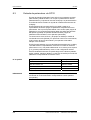
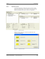
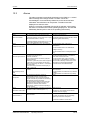
8
Parametrización
Parametrización
La entrada de datos para parametrizar la serie de equipos SIMOVERT
MASTERDRIVES se puede efectuar por caminos diversos.
Cada equipo se puede ajustar por medio de una unidad de
parametrización propia (Parameterization Unit, PMU) sin necesidad de
utilizar componentes adicionales.
Cada equipo va acompañado del software DriveMonitor, así como de
una amplia documentación electrónica en CD. Una vez instalado este,
en un PC estándar, puede comenzar la parametrización por medio de
la interface en serie del PC. El software le ofrecerá una amplia ayuda
de parametrización y una puesta en marcha guiada.
Otra posibilidad para introducir parámetros es hacerlo a través del
panel de mandos opcional OP1S y además también puede
parametrizar mediante un control a nivel de bus de campo, como por
ejemplo Profibus.
INDICACION
En la versión de firmware V1.x solo se podían modificar los parámetros
BICO en el estado del convertidor "listo para servicio". A partir de la
V2.0 (en los aparatos con performance 2) se pueden cambiar los
parámetros BICO en el estado del convertidor "servicio" posibilitando
así cambiar estructuras durante el funcionamiento (véase en la lista de
parámetros "modificable en").
ADVERTENCIA
Modificaciones involuntarias en los parámetros BICO mientras el
convertidor se encuentra en estado "servicio", pueden producir
movimientos imprevistos de los ejes.
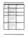
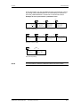
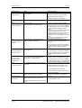
8.1
Menú de parámetros
Para estructurar el juego de parámetros archivado en el equipo, se han
recopilado en menús parámetros con las mismas características
funcionales. Un menú representa una selección de parámetros de
todos los almacenados en el equipo.
Un parámetro puede pertenecer a diferentes menús. La pertenencia de
un parámetro a un menú determinado se indica en la lista de
parámetros. La indicación se lleva a cabo por medio del nombre
correspondiente a cada menú.
Siemens AG
6SE7087-8KP50
SIMOVERT MASTERDRIVES
Instrucciones de servicio
8-1
Parametrización
03.2005
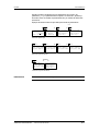
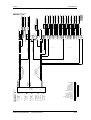
Nivel de menú 1
Selección vía
P60: Selección menú
Nivel de menú 2
(solo en OP1S)
Nivel de menú 3
(solo en OP1S)
Parámetros usuario
Parámetros generales
SST1/SST2
Bornes
P60
Conexiones bus campo
Comunicación
SIMOLINK
Palabras de mando y estado
SCB/SCI
Menú de parámetros
Canal de consigna
Motor/taco
Ajustes fijos
Datos motor
Datos taco
Regulación/control
Parametrización
rápida
Regulación de posic.
Regulación de velocid.
Regulación de intens.
Control de secuencia
Configuración
de tarjetas
Control U/f
Unidad de control
Ajuste accionamiento
Download
Diagnóstico
Upread/acceso libre
Funciones
Fallos /alarmas
Mensajes/visualizac.
Traza
Definición de la
parte de potencia
Liberaciones
Posicionador simple
Marcha sincronizada
Componentes libres
Posicionar
Tecnología
Ajustar/MDI
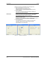
Se puede impedir el acceso a los
menús archivados sobre fondo gris
poniendo una palabra clave en el
parámetro P359.
P358 llave
Figura 8-1
8-2
P359 candado
Menús de parámetro
Instrucciones de servicio
6SE7087-8KP50 Siemens AG
SIMOVERT MASTERDRIVES
03.2005
Parametrización
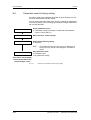
Niveles de menú
Los menús de parámetros poseen varios niveles de menús. El primer
nivel contiene los menús principales. Estos se pueden seleccionar por
medio de todas las fuentes de entrada de parámetros (PMU, OP1S,
DriveMonitor, conexiones de bus de campo).
La elección de un menú principal se realiza por medio del parámetro
P060 selección menú.
Ejemplos:
P060 = 0
selecciona el menú "parámetros del usuario"
P060 = 1
selecciona el "menú de parámetros"
...
P060 = 8
selecciona el menú "definición de parte de potencia"
Los niveles de menús 2 y 3 permiten una estructuración más detallada
del juego de parámetros. Se pueden utilizar en la parametrización de
los equipos con el panel de mando OP1S.
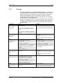
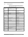
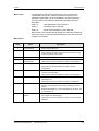
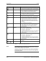
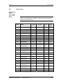
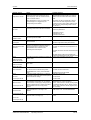
Menús principales
P060
Menú
Descripción
0
Parámetros del
usuario
•
Menú configurable
1
Menú de
parámetros
•
Contiene el juego de parámetros completo
•
Está estructurado funcionalmente para el uso de un OP1S
2
Ajustes fijos
•
Sirve para realizar un resets de parámetros al ajuste de fábrica o
al ajuste de usuario
3
Parametrización
rápida
•
Sirve para la parametrización rápida con módulos de parámetro
•
Al hacer la selección el equipo pasa al estado 21 "Download"
Configuración de
tarjetas
•
Sirve para la configuración de tarjetas opcionales
•
Al hacer la selección el equipo pasa al estado 4 " configuración de
tarjetas "
Ajuste de
accionamiento
•
Sirve para hacer una amplia parametrización de datos
importantes de motor, tacogenerador y regulación
•
Al hacer la selección el equipo pasa al estado 5 "ajuste de
accionamiento"
•
Sirve para cargar parámetros desde un OP1S, PC o un equipo de
automatización
•
Al hacer la selección el equipo pasa al estado 21 "Download"
•
Contiene el juego de parámetros completo y sirve para tener
acceso libre a todos los parámetros sin limitaciones a través de
otros menús
•
Posibilita el "Upread/Upload" (lectura) de todos los parámetros por
medio de un OP1S, PC o un equipo de automatización
•
Sirve para la definición de la parte de potencia (solo necesario
para equipos de la formas constructivas Kompakt y Chasis)
•
Al hacer la selección el equipo pasa al estado 0 "definición de la
parte de potencia"
4
5
6
7
8
Download
Upread/acceso
libre
Definición de
parte de potencia
Tabla 8-1
Menús principales
Siemens AG
6SE7087-8KP50
SIMOVERT MASTERDRIVES
Instrucciones de servicio
8-3
Parametrización
03.2005
Parámetros del
usuario
La correspondencia de parámetros y menús está básicamente
prefijada. El menú "parámetros del usuario" ocupa una posición
especial ya que se puede modificar. La correspondencia de parámetros
en este menú no está prefijada, sino que se puede cambiar. Con esto
Vd. puede realizar una recopilación en este menú de los parámetros
que sean importantes para sus requerimientos y lograr de este modo
una estructuración que corresponda a sus necesidades. La selección
de los parámetros para el usuario se hace mediante P360
(Selecc.parámetros usuario).
Llave y candado
Para evitar una parametrización no deseada del equipo y proteger el
Know-how archivado en la parametrización, se puede bloquear el
acceso a los parámetros y definir una contraseña propia.
Para eso sirven los siguientes parámetros:
♦ P358 Llave y
♦ P359 candado.
8-4
Instrucciones de servicio
6SE7087-8KP50 Siemens AG
SIMOVERT MASTERDRIVES
03.2005
Parametrización
8.2
Entrada de parámetros vía PMU
La unidad de parametrización (Parametrization Unit, PMU) sirve para la
parametrización, manejo y vigilancia del convertidor u ondulador
directamente en el equipo. Está integrada en el equipo base y consta
de un indicador de visualización de siete segmentos y varias teclas.
Display de siete segmentos para:
Estado del convertidor
Alarmas y fallos
Número de parámetro
Subir
Bajar
Modo
Indice de parámetro
Valor de parámetro
Figura 8-2
Tecla
Unidad de parametrización PMU
Significado
Modo
Subir
Función
•
Conmutación entre número, índice y valor de parámetro, en
este orden (la orden se activa al soltar la tecla)
•
Con visualización de fallo activa: acuse de fallo
Aumentar el valor visualizado:
Bajar
•
Pulsación corta: aumenta paso a paso
•
Pulsación larga: el valor aumenta en forma continua
Disminuir el valor visualizado:
Mantener pulsada
la tecla de modo y
accionar la tecla
subir
Mantener pulsada
la tecla de modo y
accionar la tecla
bajar
Tabla 8-2
•
Pulsación corta: disminuye paso a paso
•
Pulsación larga: el valor disminuye en forma continua
•
Si está activada la visualización de número de parámetro:
salta del último número a la indicación de servicio (r000) y
viceversa
•
Si está activada la visualización de fallo: cambio a número de
parámetro
•
Si está activada la visualización de valor de parámetro: se
desplaza la indicación una cifra a la derecha, en caso de no
poder representar el parámetro con 4 cifras (se produce una
intermitencia de la cifra izquierda, si a su izquierda existen
más dígitos no visibles)
•
Si está activada la visualización de número de parámetro:
salta directamente a la indicación de servicio (r000)
•
Si está activada la visualización de valor de parámetro: se
desplaza la indicación una cifra a la izquierda, en caso de no
poder representar el parámetro con 4 cifras (se produce una
intermitencia de la cifra derecha, si a su derecha existen más
dígitos no visibles)
Elementos de manejo de la PMU
Siemens AG
6SE7087-8KP50
SIMOVERT MASTERDRIVES
Instrucciones de servicio
8-5
Parametrización
Tecla modo
(Tecla P)
03.2005
Como la PMU solo dispone de un display de siete segmentos de 4
cifras, no se pueden visualizar a la vez los 3 elementos descriptivos de
un parámetro:
♦ número de parámetro
♦ índice de parámetro (si está indexado) y
♦ valor de parámetro
Por eso, se tiene que conmutar entre los distintos elementos
descriptivos. La conmutación se realiza con la tecla de modo. Después
de elegir el elemento, este se puede modificar con las teclas subir o
bajar.
Se conmuta con la tecla de modo:
•
del número al índice de parámetro
•
del índice al valor de parámetro
•
del valor al número de parámetro
Si el parámetro no está indexado,
salta directamente del número de
parámetro al valor de parámetro.
INDICACION
Número de parámetro
P
P
Valor de
parámetro
Indice de
parámetro
P
Si tiene que cambiar el valor de un parámetro, el cambio se activa por
lo general inmediatamente. Unicamente en los parámetros de
confirmación (en la lista de parámetros marcados con una estrella ‘ * ’ )
el cambio se activa después de haber hecho la conmutación del valor
al número de parámetro.
Las modificaciones que se realicen en los parámetros a través de la
PMU, se memorizan en EEPROM en forma segura contra cortes de
red, después de pulsar la tecla de modo.
8-6
Instrucciones de servicio
6SE7087-8KP50 Siemens AG
SIMOVERT MASTERDRIVES
03.2005
Parametrización
Ejemplo
En el siguiente ejemplo se muestran los pasos operativos a realizar en
la PMU para un reset de parámetros al ajuste de fábrica.
Poner P053 a 0002 y dar la orden de liberar la parametrización para la PMU
P053
∇
Ê
Ì
0000
Ê
∇
P Ì
Ê
Ì
0001
Ê
0002
P Ì
P053
Seleccionar P060
∇
Ê
Ì
P053
P060
Poner P060 a 0002 y seleccionar menú "ajustes fijos"
Ê
P060
∇
P Ì
Ê
Ì
1
Ê
P Ì
2
P060
Seleccionar P970
∇
Ê
P060
Ì
P970
...
Poner P970 a 0000 y comenzar el reset de parámetros
Ê
P970
P Ì
Ê
1
∇ Ì
Ê
0
Siemens AG
6SE7087-8KP50
SIMOVERT MASTERDRIVES
Instrucciones de servicio
P Ì
°005
8-7
Parametrización
8.3
03.2005
Entrada de parámetros vía OP1S
El panel de mandos (Operation Panel, OP1S) es un aparato opcional
para entrada y salida de datos, con el que se puede llevar a cabo la
parametrización y la puesta en servicio del equipo. La parametrización
se realiza de forma cómoda con ayuda de visualizaciones de texto en
el display.
El OP1S dispone de una memoria fija (no volátil) y está en la
capacidad de almacenar juegos de parámetros completos de forma
permanente. Por lo que se puede utilizar como archivo para juegos de
parámetros. Los juegos de parámetros deben ser leídos previamente
del aparato (Upread). Se pueden también transferir juegos de
parámetros memorizados a otros aparatos (download).
La comunicación entre el OP1S y el equipo se realiza por medio de
una interface en serie (RS485) con protocolo USS. En la comunicación,
el OP1S toma la función del maestro y los aparatos conectados
trabajan como esclavos.
El OP1S puede trabajar con una velocidad de transmisión de 9,6 kBd y
19,2 kBd. Está en la capacidad de comunicar con hasta 32 esclavos
(direcciones 0 a 31). Se puede utilizar tanto en un enlace punto a punto
(p. ej. primera parametrización) como en una configuración de bus.
Para la visualización de texto se puede elegir entre 5 idiomas (alemán,
inglés, español, francés e italiano). La elección se realiza por medio del
parámetro correspondiente del esclavo activo.
N° de pedido
INDICACION
8-8
Componente
N° de pedido
OP1S
6SE7090-0XX84-2FK0
Cable de conexión 3 m
6SX7010-0AB03
Cable de conexión 5 m
6SX7010-0AB05
Adaptador para la puerta del armario incl. 5 m cable
6SX7010-0AA00
Los ajustes de parámetros para los aparatos conectados al OP1S se
encuentran en la documentación correspondiente a esos aparatos
(compendio).
Instrucciones de servicio
6SE7087-8KP50 Siemens AG
SIMOVERT MASTERDRIVES
03.2005
Parametrización
LC-Display (4 lineas x 16 signos)
LED rojo
LED verde
Conector SUB D de
9 polos en la parte
posterior
Fault
Run
Inversión
CON.
I
DES.
O
Subir
Bajar
P
Modo
Marcha a
impulsos
Jog
7
8
9
4
5
6
1
2
3
0
+/-
Reset
0 a 9: cifras
Reset (acuse de recibo)
Signo
Figura 8-3
Panel de mando OP1S
100.0A 380.0V 00
#-300.000Hz
*-300.000Hz
Betrieb
Fault
Run
I
O
P
S IE ME NS
USS-Bus
Jog
7
8
9
4
5
6
1
2
3
0
+/-
Reset
P
A
S1
S
US
OP1S
Cable de unión
2
1
2
1
9
8
7
6
OP1S:
Aparato:
Conector SUB D de 9 polos (hembra)
Conector SUB D de 9 polos (macho)
Figura 8-4
INDICACION
X101 B
5
48
RS
5
4
3
e
7
6
5
4
3
nt
ia
ed
m
9
8
X103 C
Ejemplo de un enlace punto a punto entre OP1S y Kompakt PLUS
En estado de suministro o después de aplicar un reset de parámetros
al ajuste de fábrica, se puede realizar directamente un acoplamiento
punto a punto con el OP1S y comenzar con la parametrización.
Siemens AG
6SE7087-8KP50
SIMOVERT MASTERDRIVES
Instrucciones de servicio
8-9
Parametrización
Tecla
O
Jog
P
03.2005
Significado
Conexión
•
Conexión del accionamiento (liberación del control de
motor). La función se tiene que liberar con P554.
Desconexión
•
Desconexión del accionamiento. Dependiendo de la
parametrización a través de DES.1, DES.2 o DES.3. La
función se tiene que liberar con los parámetros de P554
a P560.
Marcha a impulsos
•
Marcha a impulsos con valor de consigna para marcha a
impulsos 1 (solo activa en estado "listo para conexión").
La función se tiene que liberar con P568.
Inversión
•
Se invierte el sentido de giro del accionamiento
(inversión). La función se tiene que liberar con P571 y
P572.
Modo
•
Selección de los menús y conmutación entre número,
índice y valor de un parámetro, en este orden . Se
visualiza cual de ellos está activo por medio del cursor
en el LC-Display (la orden se activa al soltar la tecla)
•
Se finaliza la entrada de cifras numéricas
•
Salida de un menú determinado
•
Si hay visualización activa de fallo: acuse de fallo. La
función se tiene que liberar con P565.
•
Aumentar el valor visualizado:
•
Pulsación corta: aumenta paso a paso
•
Pulsación larga: el valor aumenta en forma continua
•
Con potenciómetro motorizado activo: incrementa la
consigna. La función se tiene que liberar con P573.
•
Disminuir el valor visualizado:
•
Pulsación corta: disminuye paso a paso
•
Pulsación larga: el valor disminuye en forma continua
•
Con potenciómetro motorizado activo: disminuye la
consigna. La función se tiene que liberar con P574.
Signo
•
Cambiar el signo para meter valores negativos
Cifras
•
Entrada de cifras numéricas
Reset
Reset
Subir
Bajar
+/0
a
9
Tabla 8-3
INDICACION
Función
Elementos de operación del OP1S
Si Vd. modifica el valor de un parámetro, el cambio se activará
inmediatamente después de pulsar la tecla de modo (P).
Las variaciones en los parámetros que se realicen a través del OP1S,
se memorizan en EEPROM de forma segura contra cortes de red,
después de pulsar la tecla de modo (P).
8-10
Instrucciones de servicio
6SE7087-8KP50 Siemens AG
SIMOVERT MASTERDRIVES
03.2005
Parametrización
Existen también visualizaciones de parámetros sin número de
parámetro, p. ej. la parametrización rápida o la selección ”ajuste fijo”.
En estos casos se realiza la parametrización por medio de diferentes
submenús.
Ejemplo de esta manera de proceder para reset de parámetros.
2x
Ê
0.0
#
*
Listo
P Ì
Ê
A 0 V 00 MotionControl
0.00 min-1 *Selección menú
0.00 min-1 OP: Upread
OP: Download
conexión
P Ì
Ê
∇ Ì
Selección menú
Selección menú
*Parám.usuario
*Parám.usuario
Menú parámetr..
Menú parámetr..
Ajuste fijo...
#Ajuste fijo...
Selección ajustes fijos
Ê
∇ Ì
Ê
P Ì
Ê
∇
P Ì
Ì
Ajuste fijo
Ajuste fijo
Ajuste fábrica
Ajuste fábrica
*Sel.ajuste fábr *Sel.ajuste fábr
Ajuste fábrica
#Ajuste fábrica
Ajuste fábrica
#Ajuste fábrica
*Sin ajuste fábr *Sin ajuste fábr
Selección ajuste de fábrica
P Ì
Esperar
Ê
Ì
Ajuste fábrica
Selección menú
#Ajuste fábrica
*Parám.usuario
*Sin ajuste fábr
Menú parámetr..
busy............
Ajuste fijo...
Comienza el ajuste de fábrica
INDICACION
En el estado ”servicio” no es posible iniciar un reset de parámetros.
Siemens AG
6SE7087-8KP50
SIMOVERT MASTERDRIVES
Instrucciones de servicio
8-11
Parametrización
8.4
03.2005
Entrada de parámetros vía DriveMonitor
INDICACION
Encontrará información más detallada para DriveMonitor en
ayuda online (botón
8.4.1
Instalación y enlaces
8.4.1.1
Instalación
o tecla F1).
En el suministro de los equipos de la serie MASTERDRIVES está
incluido un CD. La herramienta de manejo que se encuentra en él
(DriveMonitor) se instala automáticamente desde el mismo CD. Si en la
unidad de CD del PC se ha activado "Notificar la inserción
automáticamente", arranca una guía para el usuario al insertar el CD.
Con ella se puede instalar DriveMonitor. Si esto no ocurre utilice el
archivo "Autoplay.exe" en el directorio base del CD para arrancar.
8.4.1.2
Conexión
Existen dos posibilidades de comunicar un PC con un SIMOVERT
MASTERDRIVES mediante una interface USS. Las unidades de la
serie SIMOVERT MASTERDRIVES poseen tanto una interface RS232
como una RS485.
Interface RS232
La interface en serie que se encuentra incorporada en el PC de forma
estándar, trabaja como una interface RS232. No es adecuada para
funcionar en interconexión por bus, está diseñada para operar solo con
una unidad SIMOVERT MASTERDRIVES.
9
8
7
6
5
5
4
4
3
3
2
2
1
1
Conector
hembra COMx
en el PC
Figura 8-5
ATENCIÓN
8-12
9
8
7
6
X300:
1 n.c. (not connected)
(Compacto PLUS: RS232 Id)
2 RxD (RS232)
3 Rx+/Tx+ (RS485)
4
5 Masa
6 +5V (OP1S)
7 TxD (RS232)
8 Rx-/Tx- (RS485)
9 Masa
Aparato
-X300 (Compacto PLUS -X103)
Conector SUB-D de 9 polos (macho)
Cable de enlace para comunicar una PC COM(1-4) con SIMOVERT
MASTERDRIVES X300
DriveMonitor no se debe operar vía conector Sub-D X300, cuando ya
está en uso la otra interface (SST1) paralela a esta, p.ej. interconexión
por bus con maestro SIMATIC.
Instrucciones de servicio
6SE7087-8KP50 Siemens AG
SIMOVERT MASTERDRIVES
03.2005
Parametrización
Interface RS485
La interface RS485 tiene capacidad multipunto y por eso es adecuada
para utilizarla en interconexión por bus. Con ella se pueden conectar
31 SIMOVERT MASTERDRIVES a un PC. En el PC se necesita una
interface RS485 integrada o un convertidor de interfaces RS232 ↔
RS485. En el aparato se encuentra una interface RS485 en el conector
-X300 (Kompakt PLUS -X103) integrada. Cable: Véase la asignación
de pines del conector -X300 y los manuales del convertidor de
interfaces.
8.4.2
Establecimiento de la comunicación DriveMonitor – unidad
8.4.2.1
Ajustar interface USS
La interface se configura en el menú Herramientas Æ Preferencias
ONLINE ....
Figura 8-6
Preferencias ONLINE
Siemens AG
6SE7087-8KP50
SIMOVERT MASTERDRIVES
Instrucciones de servicio
8-13
Parametrización
03.2005
Existen las siguientes posibilidades de ajuste (Figura 8-7):
♦ Ficha "Tipo de bus", para seleccionar;
USS (funcionamiento vía interface en serie)
Profibus DP (solo si se opera DriveMonitor bajo Drive ES).
♦ Ficha "Interface"
Para indicar la interface COM del PC (COM1 a COM4) y la
velocidad de transmisión deseadas.
INDICACION
Ajuste la velocidad de transmisión de acuerdo a la velocidad de
transmisión (P701) que haya parametrizado en SIMOVERT
MASTERDRIVES (ajuste de fábrica 9600 baud).
Además se pueden ajustar:
El régimen de trabajo del bus si opera con RS485; Ajuste según la
descripción de convertidor de interfaces RS232/RS485
♦ Ficha "Ampliación"
Las repeticiones de las tareas y el tiempo de retardo de la
respuesta. Puede elevar los valores si hay a menudo
irregularidades en la comunicación.
Figura 8-7
8-14
Configuración de interfaces
Instrucciones de servicio
6SE7087-8KP50 Siemens AG
SIMOVERT MASTERDRIVES
03.2005
8.4.2.2
Parametrización
Arrancar con búsqueda en el bus USS
El DriveMonitor arranca con la ventana para el accionamiento vacía. El
bus USS buscará los aparatos conectados a través del menú "USSEstablecer conexión ONLINE".
Figura 8-8
INDICACION
Arrancar con búsqueda en el bus USS
El menú "USS-Establecer conexión ONLINE " será aplicable a partir de
la versión 5.2.
Figura 8-9
Búsqueda ONLINE de accionamientos
La búsqueda se lleva a cabo solamente con la velocidad de
transmisión del bus USS ajustada. Para cambiarla utilice "Extras >Ajustes en línea", véase sección 8.4.2.1.
Siemens AG
6SE7087-8KP50
SIMOVERT MASTERDRIVES
Instrucciones de servicio
8-15
Parametrización
8.4.2.3
03.2005
Creación de juegos de parámetros
Mediante el menú ArchivoÆ NuevoÆ... se puede crear un
accionamiento nuevo para su parametrización (véase Fehler!
Verweisquelle konnte nicht gefunden werden.). El sistema genera
un archivo Download (*.dnl), donde además están almacenados los
datos característicos del accionamiento (tipo, versión). El archivo se
puede crear sobre la base de un juego de parámetros vacío o sobre la
base del ajuste de fábrica.
Figura 8-10
Creación de un nuevo accionamiento
Basado en ajuste de fábrica:
♦ La lista de parámetros está preasignada con los valores del ajuste
de fábrica.
Juego de parámetros vacío:
♦ Para crear lista de parámetros según se necesite
Si se desea reparametrizar algún juego de parámetros existente hágalo
llamando el archivo Download correspondiente mediante el menú
ArchivoÆ Abrir. Ahí se pueden abrir los últimos cuatro accionamientos
con "zuletzt bearbeitete Parametersätze".
Cuando se crea un nuevo accionamiento, se abre la ventana
"Propiedades del accionamiento" (Figura 8-11). Especifique en ella lo
siguiente:
♦ En la lista desplegable "Tipo de equipo" seleccione el tipo (p.ej.
MASTERDRIVES MC). Solo se pueden seleccionar unidades que
estén archivadas.
♦ En la lista desplegable "Versión del equipo" seleccione la versión de
software del aparato. Las bases de datos para versiones nuevas se
pueden crear al arrancar la parametrización Online.
♦ La dirección del accionamiento en el bus solo se debe poner si va a
trabajar Online (conmutación por medio del botón Online/Offline)
8-16
Instrucciones de servicio
6SE7087-8KP50 Siemens AG
SIMOVERT MASTERDRIVES
03.2005
INDICACION
Parametrización
La dirección de bus indicada tiene que concordar con la dirección de bus
SST (P700) parametrizada en SIMOVERT MASTERDRIVES.
Con el botón "Abrir la conexión a la red" no se le asigna al
accionamiento ninguna dirección de bus.
INDICACION
El cuadro "Número de PZD" carece de significado para la
parametrización de MASTERDRIVES y se debe dejar a "2".
Si cambia el valor debe asegurarse de que el valor que ha ajustado en
el programa concuerde siempre con el valor del parámetro P703 en el
accionamiento.
Figura 8-11
Creación del archivo; propiedades del accionamiento
Después de confirmar las propiedades del accionamiento con
"Aceptar" se tiene que establecer el lugar de almacenamiento y el
nombre del archivo download.
Siemens AG
6SE7087-8KP50
SIMOVERT MASTERDRIVES
Instrucciones de servicio
8-17
Parametrización
03.2005
8.4.3
Parametrización
8.4.3.1
Estructura de la lista de parámetros, parametrización vía DriveMonitor
En principio, la parametrización a través de la lista de parámetros se
lleva a cabo del mismo modo que la parametrización mediante la PMU
(véase el capítulo 6 "Secuencia de parametrización"). La lista de
parámetros le ofrece las siguientes ventajas:
♦ Visualización global de una gran cantidad de parámetros
♦ Visualizaciones de texto para nombres de parámetro, número y
texto de índice, valores de parámetro, binectores y conectores
♦ Si se modifica el parámetro: Visualización de los límites del
parámetro o bien los valores admisibles del parámetro
La lista de parámetros tiene la siguiente estructura:
Número
d.celda
Nombre de
celda
Función
1
Número de
parámetro
Se visualiza el número del parámetro. El usuario solo puede cambiar la
celda en el menú Free parameterization.
2
Nombre
Se visualiza el nombre del parámetro según está en la lista de parámetros
3
Indice del
parámetro
Se visualiza el índice de parámetro de los parámetros indexados. Para ver
más índices que el número 1, haga clic en el símbolo [+]. La visualización se
expande y muestra todos los índices del parámetro.
4
Texto indexado
Significado del índice correspondiente
5
Valor de
parámetro
Se visualiza el valor del parámetro. Modificable con doble clic o Seleccionar
y Enter.
6
Dimensión
Magnitud física del parámetro, si la posee.
8-18
Instrucciones de servicio
6SE7087-8KP50 Siemens AG
SIMOVERT MASTERDRIVES
03.2005
Parametrización
Mediante el botón Offline, Online-RAM, Online-EEPROM (Figura 8-12
[1]) puede cambiar de Modo. Al cambiar a modo Online se realizará
una identificación del aparato. Si el aparato real no concuerda con el
configurado (tipo, versión de SW), aparece una alarma. Si se ha
detectado una versión de SW desconocida, tiene la posibilidad de crear
la base de datos correspondiente (tarda unos minutos).
1
2
Figura 8-12
Ventana para el accionamiento/lista de parámetros
La ventana para el accionamiento del DriveMonitor posee un árbol de
directorios para navegar (Figura 8-12 [2]). Esta ayuda auxiliar la puede
ocultar (menú ver selección de parámetros).
Siemens AG
6SE7087-8KP50
SIMOVERT MASTERDRIVES
Instrucciones de servicio
8-19
Parametrización
03.2005
La ventana para el accionamiento posee todos los elementos para la
parametrización y el manejo del aparato conectado. En la última barra
se muestra el estado de la conexión al aparato:
Conexión y aparato ok
Conexión ok, aparato en estado "fallo"
Conexión ok, aparato en estado "alarma"
Aparato se parametrizará en offline
No se puede establecer conexión con el aparato
(parametrización solo posible en offline).
INDICACION
8-20
Si no se puede establecer ninguna conexión con el aparato porque no
existe en la realidad o porque aún no está conectado, puede hacer una
parametrización Offline cambiando al modo Offline. En el modo Offline
el juego de datos de parámetro es editable. De este modo se puede
crear un archivo download individual y cargarlo más tarde en el
aparato.
Instrucciones de servicio
6SE7087-8KP50 Siemens AG
SIMOVERT MASTERDRIVES
03.2005
Drive Navigator
Parametrización
Sirve para tener acceso rápido a funciones importantes del
DriveMonitor.
Los ajustes para el Drive Navigator se encuentran bajo Extras ->
Opciones (Figura 8-14):
Figura 8-13
Drive Navigator
Figura 8-14
Cuadro del menú opciones
Siemens AG
6SE7087-8KP50
SIMOVERT MASTERDRIVES
Instrucciones de servicio
8-21
Parametrización
03.2005
Barra de botones del Drive Navigator
8-22
=
Puesta en servicio guiada
=
Ir directamente al lista de parámetros
=
Diagnóstico general
=
Guardar parámetros de accionamiento en
un archivo de seguridad
=
Transferir archivo de parámetros al
accionamiento
=
Cargar aplicación estándar
=
Puesta en servicio guiada de Tecnología
F01
=
Máscaras del posicionador simple
Instrucciones de servicio
6SE7087-8KP50 Siemens AG
SIMOVERT MASTERDRIVES
03.2005
8.4.3.2
Parametrización
Diagnóstico general
Con el menú DiagnósticoÆ Diagnóstico general se abre el cuadro
general que se ilustra abajo. Ahí se muestra en texto claro tanto las
alarmas y los fallos activos como su número y su significado.
Figura 8-15
Diagnóstico general
Mediante el botón Diagnóstico avanzado se pueden abrir otras
ventanas para diagnóstico.
Figura 8-16
Diagnóstico avanzado
Siemens AG
6SE7087-8KP50
SIMOVERT MASTERDRIVES
Instrucciones de servicio
8-23
Parametrización
8.5
03.2005
Reset de parámetros al ajuste de fábrica
El ajuste de fábrica es un estado definido de todos los parámetros de
un equipo. En ese estado se suministran todos los equipos.
Por medio del reset de parámetros al ajuste de fábrica se puede
restablecer en cualquier momento ese estado original y anular todas
las modificaciones efectuadas en los parámetros del equipo desde su
suministro.
Liberación de parametrización
6: Se permite cambiar parámetros a través de la PMU y la
interface en serie SST1 (OP1S y PC)
P053 = 6
P060 = 2
Selección menú "ajuste fijo"
P366 = ?
selección ajuste de fábrica
0: Estándar
Indicación: Este parámetro ha sido correctamente
ajustado antes del suministro y solo se tiene
que modificar en casos excepcionales.
Comienzo del reset de parámetros
0: Reset de parámetros
1: Ninguna modificación de parámetros
P970 = 0
El equipo realiza el reset
de parámetros y abandona
los "ajustes fijos".
Figura 8-17
8-24
Secuencia del reset de parámetros al ajuste de fábrica
Instrucciones de servicio
6SE7087-8KP50 Siemens AG
SIMOVERT MASTERDRIVES
03.2005
8.6
Parametrización
Parametrización vía download
Download con OP1S El panel de mandos (Operation Panel OP1S) está en la capacidad de
leer y memorizar juegos de parámetros de los equipos (Upread). Estos
juegos de parámetros se pueden transferir a otros equipos por
download. Por eso, la aplicación preferente para un download por
medio de OP1S es la parametrización de aparatos de repuesto en el
servicio de asistencia. Para el download con OP1S se parte de la base
que el aparato se encuentra en estado de suministro. Los parámetros
correspondientes a la definición de la parte de potencia no se
transfieren. (Véase al respecto el párrafo "parametrización detallada,
definición de la parte de potencia"). El PIN que se ha registrado para
liberar las funciones tecnológicas opcionales tampoco se transcribe
con el download.
Con la función ”OP: Download” se puede transferir, un juego de
parámetros memorizado en un OP1S, a un esclavo conectado.
Partiendo del menú base se elige con la tecla ”bajar” o ”subir” la
función ”OP: Download” y se activa a través de ”P”.
Ê
MotionControl
*Selección menú
OP: Upread
#OP: Download
P Ì
Download
*1909199701
MASTERDRIVES MC
PLUS
Ejemplo de selección y activación de la función "download"
Ahora se tiene que seleccionar uno de los juegos de parámetros que
se encuentran archivados en el OPS1 con las teclas "subir" o "bajar"
(visualización en la segunda línea). Con "P" se confirma la
identificación que se ha seleccionado. A partir de este momento se
puede visualizar la identificación de esclavo con las teclas "subir" o
"bajar". La identificación de esclavo incluye un distintivo característico
del equipo por ejemplo: potencia asignada, número de pedido, versión
software, etc..
A continuación se pone en marcha la función "download" pulsando "P"
y, durante el procesamiento de la misma, en el OP1S se visualiza el
número de parámetro.
Ê
Download
*1909199701
MASTERDRIVES MC
PLUS
P Ì
Ê
Download
*1909199701
MASTERDRIVES MC
PLUS
P Ì
MotionControl 00
Download
Pxxx
Ejemplo: confirmación de la identificación y comienzo del proceso "download"
Con la tecla ”reset” se puede interrumpir el proceso en cualquier
momento. Si el download se realiza completamente, aparece el
mensaje ”Download ok” y se pasa al menú base.
Siemens AG
6SE7087-8KP50
SIMOVERT MASTERDRIVES
Instrucciones de servicio
8-25
Parametrización
03.2005
Si una vez seleccionado el juego de datos para el download, la
identificación de la versión software memorizada, no coincide con la
versión software del aparato, aparece aproximadamente por 2 seg. un
mensaje de fallo. Seguidamente aparece la pregunta si tiene qué ser
interrumpido el proceso download.
Ê
Download
*1909199701
MASTERDRIVES MC
PLUS
Sí:
No:
8.7
P Ì
Ê
Download
*1909199701
MASTERDRIVES MC
PLUS
P Ì
Ê
Fallo:
Identificación
desigual
2s Ì
MotionControl 00
Inter. Download?
#Sí
No
el proceso ”download” se interrumpe.
el proceso ”download” se realiza.
Parametrización con módulos de parámetros
En el aparato se encuentran definidos y almacenados módulos de
parámetros ordenados funcionalmente. Estos módulos se pueden
combinar entre sí, consiguiéndose de este modo, con pocos pasos de
parametrización, adaptar el aparato a la aplicación requerida. No es
necesario tener conocimiento en detalle sobre el juego de parámetros
completo del aparato.
Existen módulos de parámetros a disposición para los siguientes
grupos funcionales:
1. Motores
2. Tacos-motor
3. Modos de regulación
4. Fuente de órdenes y consignas
La parametrización se realiza de tal modo que Vd. elige de cada grupo
funcional un módulo de parámetro y después comienza la
parametrización rápida. Se hace un reset de parámetros al ajuste de
fábrica y después se ajustan automáticamente los parámetros de forma
que (según se haya seleccionado), se establece la funcionalidad de
regulación deseada. Los parámetros necesarios para el ajuste
detallado de la estructura de regulación se añaden de forma
automática al menú del usuario.
INDICACION
8-26
Si ya se han realizado modificaciones de parámetros en el equipo, se
recomienda hacer un reset de parámetros al ajuste de fábrica, antes de
llevar a cabo la ”parametrización rápida”.
Instrucciones de servicio
6SE7087-8KP50 Siemens AG
SIMOVERT MASTERDRIVES
03.2005
Parametrización
P060 = 3
Selección del menú "parametrización rápida"
Tensión de conexión del equipo en V
Equipos CA: Valor efectivo de la corriente alterna
Equipos CC: Tensión del circuito intermedio
P071 = ?
Tipo de motor
0: Ningún motor conectado
1: Motor servosincrónico 1FT6/1FK6
2: Motor servoasincrónico 1PH7(=1PA6)/1PL6/1PH4
5: Torquemotor 1FW3
P095 = ?
P095 = 1
2
5
Entrada del número codificado para el motor conectado
1FK6/1FT6 (véase la lista en el capítulo 8.8)
P096 = ?
Entrada del número codificado para el motor conectado
1PH7(=1PA6)-, 1PH4-, 1PL6 (véase la lista en el capítulo 8.8)
P097 = ?
P099 = ?
P130 = ?
0, 1, 2, 3, 5, 6,
7
4
P147.1 = ?
P367 = ?
Entrada del número codificado para el motor conectado
1FW3 (véase la lista en el capítulo 8.8)
Selección del tipo tacogenerador del motor
0: Detección de captador automática
1: Resolver de 2 polos
2: Resolver con el par de polos del motor
3: Encoder 2048/revol.
4: Multiturn 2048/revol.
5: Generador de impulsos 1024/revol.
7: Encoder sin pista C/D 2048/revol. (a partir de V1.30 SW)
Con encoders sin pista C/D no está definida la posición
inicial absoluta. Solo se pueden usar con motores
asíncronos. La posición se corrige con un impulso de
puesta a cero igualmente empalmado.
Los motores asíncronos 1PA6, 1PL6, 1PH4 y 1PH7 con
encoder por lo general se suministran con un ERN1381
sin pista C/D.
Selección del captador multiturm
1: EQN1325 (2048 impulsos)
2: ECN1313 (2048 impulsos)
6: EnDat
7: EQI1325 (32 impulsos)
8: EQN1125 (Fa. Heidenhain) EnDat
9: ECN1113 (Fa. Heidenhain) EnDat
Selección del tipo de regulación
0: Control U/f
2: Regulación de par
3: Regulación de velocidad
Siemens AG
6SE7087-8KP50
SIMOVERT MASTERDRIVES
Instrucciones de servicio
8-27
Parametrización
03.2005
Selección: fuente de órdenes y consignas
0: sin uso
1: Entrada analógica y regletero de bornes
2: Valores de consigna fija y regletero de bornes
3: Potenciómetro motorizado y regletero de bornes
4: USS
5: sin uso
6: PROFIBUS (CBP2)
7: OP1S y valores de consigna vía SST1
8: OP1S y potenciómetro motorizado vía SST1
P368 = ?
P368 =
0, 1, 2, 3
4 7, 8
6
P700.1 = ?
Dirección de bus USS
P918.1 = ?
P370 = 1
P060 = 0
Dirección PROFIBUS
Inicio de la parametrización rápida
0: Sin modificación de parámetros
1: Modificación de parámetros según la combinación
seleccionada de módulos de parámetros
Indicación:
Después de comenzar lo primero que se produce es un
ajuste de fábrica automático con P366 = 0, posteriormente
se realiza la parametrización correspondiente
Regreso al menú del usuario
Figura 8-18
Módulos de planos
funcionales
8-28
Secuencia para la parametrización con módulos de parámetros
Después del diagrama de operaciones se encuentran representados
los módulos de planos funcionales (planos funcionales ) para los
módulos de parámetros almacenados en el software del aparato. En
las primeras páginas se encuentran
♦ las fuentes de órdenes y consignas
♦ las salidas analógicas y los parámetros de observación y
♦ los tipos de control y regulación.
Con esto es posible agrupar con exactitud los planos funcionales que
correspondan a la combinación seleccionada de la fuente de
órdenes/consignas y el tipo de control/regulación. Así se obtiene tanto
una visión global sobre la funcionalidad parametrizada en el aparato,
como sobre la asignación de bornes.
Los parámetros funcionales y de observación que se proporcionan en
los planos funcionales se transfieren automáticamente al menú de
usuario y pueden ser desde ahí vigilados y modificados.
Los números de parámetro del menú del usuario se incorporan al
P360.
Instrucciones de servicio
6SE7087-8KP50 Siemens AG
SIMOVERT MASTERDRIVES
03.2005
Parametrización
Fuente órdenes y consignas:
Regletero de bornes
y entrada analógica
-X101/1
P24
-X101/2
M24
-X101/3
1 = servicio
-X101/4
0 = fallo
-X101/5
0 = alarma
-X101/6
1 = liberación ondulador
-X101/7
1 flanco = acuse
-X101/8
1 = CON. 0 = DES.1
Escalada EA
P630
Entrada diferencial
+/- 10 V
Offset EA
P631
-10 V ... + 10V
corresp.
-100 % ... +100 %
AI+
-X101/9
A
Alisamiento EA
P634
D
AI-X101/10
Modo regulación:
Regulación
velocidad
r003 tensión da salida
r004 intensidad de salida
Velocidad
referencia
P353
r006 tensión circuito intermedio
Norm.
n-Reg. Kp1 n-Reg. Tn
P235.1 P240.1
Vis. conec. vel.
r041.1
(= consigna
velocidad)
VCF
M(lím.,1)
P263.1
n(máx, giro pos.)
P452.1
Regul.
intensidad
Tiempo
aceleración P462.1
Salida analógica
+/- 10 V
-X101/11
AA
n(máx, giro neg.)
P453.1
Tiempo
deceler. P464.1
Offset SA
P644.1
A
-X101/12
VCF
M(lím.,2)
P264.1
y[V]=
Taco
motor
Alisamiento SA
P642.1
Escalada SA
P643.1
y
D
Motor
3~
Vis. conec. vel.
r041.2
(=valor real de velocidad)
x
x
P643.1
100 %
Tipo de taco:
Resolver
Datos del resolver:
- 2 polos
Datos de reproducción de impulsos:
- 1024 impulsos/revolución
Reproducción de impulsos
(solo en SBR2)
6
SBR1/2
-X410/90
Canal A+
sen +
-X414/3
-X410/91
Canal A-
sen -
-X414/4
-X410/92
Canal B+
cos+
-X414/6
-X410/93
Canal B-
cos-
-X414/7
-X410/94
Impul.puesta 0 +
Excitación
-X414/9
-X410/95
Impul.puesta 0 -
MExcitación
-X414/11
Soporte pantalla
Siemens AG
6SE7087-8KP50
SIMOVERT MASTERDRIVES
Instrucciones de servicio
8-29
Parametrización
8-30
03.2005
Instrucciones de servicio
6SE7087-8KP50 Siemens AG
SIMOVERT MASTERDRIVES
03.2005
Parametrización
Fuente de órdenes y consignas:
Regletero de bornes y valores de consigna fijos (VCF)
-X101/1
P24
-X101/2
M24
-X101/3
1 = servicio
-X101/4
0 = fallo
-X101/5
VCF Bit 0
-X101/6
VCF Bit 1
-X101/7
1-flanco = acuse
-X101/8
1 = CON. 0 = DES.1
VCF1
0 0
VCF2
0 1
VCF3
1 0
VCF4
1 1
Modo de regul.:
Regulación
de par
r003 tensión de salida
r004 intensidad de salida
Par de
referencia
P354
r006 tensión circuito intermedio
Norm.
Vis.conect.de par
r039.1
(=consigna de
par)
VCF M(lím,1)
P263.1
Regul.
intensid.
Motor
3~
VCF M(lím,2)
P264.1
Vigilancia
velocidad
taco
motor
n(máx, giro pos.) n(máx, giro neg.)
P452.1 P453.1
Salida analógica
+/- 10 V
-X101/12
SA
A
y
D
Escalada SA
P643.1
y[V]=
Alisam.SA
P642.1
x
x
P643.1
100 %
Vis.conect.de par
r039.2
(=valor real
velocidad)
Modelo
Vis.conect.velocidad
r041.2
(=Val.real velocidad)
-X101/11
Offset SA
P644.1
Tipo de taco:
Generador de impulsos
La información completa para conectar el generador
de impulsos se encuentra en las instrucciones de
servicio de la SBP (referencia 6SE7087-8NX84-2FA0).
Datos del generador de impulsos:
- Taco HTL (15 V)
- 1024 Inc.
- Sin canal de control
SBP
UB
-X400/60
5
-X400/61
Canal A+
-X401/68
Canal B+
-X401/70
Imp. puesta a cero+
-X401/72
Soporte pantalla
Siemens AG
6SE7087-8KP50
SIMOVERT MASTERDRIVES
Instrucciones de servicio
8-31
Parametrización
8-32
03.2005
Instrucciones de servicio
6SE7087-8KP50 Siemens AG
SIMOVERT MASTERDRIVES
03.2005
Parametrización
Fuente de órdenes y consignas:
Regletero de bornes y potenciómetro motorizado
-X101/1
P24
-X101/2
M24
-X101/3
1 = servicio
-X101/4
0 = fallo
-X101/5
Tiemp.acel.pot.mot. Tiemp.decel.pot.mot.
P431 P432
Pot.mot.(máx.)
P421
1 = subir potenc.motoriz.
-X101/6
1 = bajar potenc.motoriz.
-X101/7
1-flanco = acuse
-X101/8
1 = CON.0 = DES.1
Pot.mot.(mín.)
P422
Conf. pot.mot.
P425
00x0 = ... no se memoriza después de DES.
00x1 = ... se memoriza después de DES.
Modo de regulación:
Control U/f
r003 tensión de salida
r004 intensidad de salida
Velocid.
de ref.
P353
r006 tensión circuito intermedio
Norm.
Caract.tensión1
P327
Frecuencia de refer.
n(máx, giro pos.)
P352
P452.1
U
.3 .4
Norm.
Elevación
P325
n(máx, giro neg.)
P453.1
Tiemp.acelerac. Tiemp.decelerac.
P462.1 P464.1
Motor
3~
.2
.1
.1 .2
.3 .4
f
Caract. frecuencia1
P326
-X101/11
SA
-X101/12
Offset SA
P644.1
A
Escalada SA
P643.1
y
D
y[V]=
x
P643.1
100 %
Alisamiento SA
P642.1
x
Vis.conect.frecuencia
r043.2
(=valor real frecuencia)
Salida analógica
+/- 10 V
Taco
motor
Tipo de taco:
Sin generador
Siemens AG
6SE7087-8KP50
SIMOVERT MASTERDRIVES
Instrucciones de servicio
8-33
Parametrización
8-34
03.2005
Instrucciones de servicio
6SE7087-8KP50 Siemens AG
SIMOVERT MASTERDRIVES
03.2005
Parametrización
Listo conexión
Listo servicio
Servicio
Fallo activo
DES.2 activa
DES.3 activa
Bloqueo conexión
Alarma activa
Desviac.cna.-real
Mando demand.PZD
Fallo subtensión
Excitación CP
GdR activo
Reserva
<1> Los parámetros de interface P700 a P704
permanecen igual cuando se pone el
parámetro P370=1 vía SST1 (p.ej. DriveMonitor).
Cna.vel.pos./neg.
USS
Cna.compar.alcanz.
Fuente de órdenes y consignas:
1
15
<1>
PKW
Datos-pal.1
Datos-pal. 2
PKW
PKW
Datos-pal. 1
Datos-pal. 2
Recepción
Valor real
Valor consigna
STW1
1
DES.2
CON./DES.1
1
DES.3
1
Liber.ondulador
Lib.consign.
1
Arranca GdR
1
LiberaciónGdR
0
Acuse
1 0
Mar.impuls.bit2
1
Mar.impuls.bit1
0
0 1
SG pos.
Fallo externo
Propuesta:
15
0 0
Man.dem.PZD
Tiemp.inte.
telegr: 0 =
ning.vigilan.
PKW
Emisión
SG neg.
RS485N
Vel.transm:
9.6 KB
0
ZUW1
Subir pot.mot.
-X100/36
PKW:4
RS485P PZD:2
Bajar pot.mot.
-X100/35
Siemens AG
6SE7087-8KP50
SIMOVERT MASTERDRIVES
Instrucciones de servicio
8-35
Parametrización
8-36
03.2005
Instrucciones de servicio
6SE7087-8KP50 Siemens AG
SIMOVERT MASTERDRIVES
CB dirección bus
0 ... 200
P918.01 (3)
CB/TB interrup.teleg.
0 ... 6500 ms
P722.01 (10)
P722.01 =0 :
sin vigilancia
CB parámetro 11
0 ... 65535
P721.01 a .05
CB parámetro 10
0 ... 65535
P720.01
••••••
CB parámetro 1
0 ... 65535
P711.01
Configuración CB
Lámina [120]
Recepción
Emisión
Lámina [125]
Siemens AG
6SE7087-8KP50
SIMOVERT MASTERDRIVES
Instrucciones de servicio
ZUW1
PZD1 (palab.datos1)
1
0
PKW
PKW
••
PKW
Reservado para
operaciones de
lectura de datos de
parámetros
PZD1 (palab.datos 1)
PZD1 (palab.datos 1)
n(real) de lám. [500a.8]
ZUW1
r552
de lám.
[200]
Isq(real) de lám. [390.4]
f(cons.U/f) de lám. [400.5]
Ningún paro GdR
Liberación consigna
B3105
B3106
Subir pot.mot.
Bajar pot.mot.
Fallo externo
Bit14 B3114
Bit15 B3115
B3112
Giro negativo
• • • • • •
8-37
a lám [180]
palabra de
mando 1
r550
P574.1
Fte. Bajar pot.mot
B (3114)
P573.1
Fte. Subir pot.mot.
B (3113)
P572.1
Fte. Giro negativo
B (3112)
Mand.deman.PZD P571.1
Fte. Giro positivo
Giro positivo
B (3111)
B3110
B3111
Mar.impul.bit1
P569.1
Fte.m.impul. bit1
B (3109)
P568.1
Fte.m.impul. bit0
B (3108)
P566.1
Fte. 2 acuse
B (3107)
P564.1
Fte. Liber. consigna
B (3106)
P563.1
Fte. Ningún paro GdR
B (3105)
P562.1
Fte.Liber. GdR
B (3104)
P561.1
Fte.Liber.ondulador
B (3103)
P558.1
Fte.1 DES3 (paro ráp)
B (3102)
P555.1
Fte.1 DES2
B (3101)
B3109
Mar.impul.bit0
Liberación GdR
B3104
B3108
Liber.ondulador
B3103
Acuse
DES.3 (paro ráp.)
B3102
B3107
DES.2 (electr.)
B3101
P554.1
Fte.CON/DES1
B (3100)
Consigna principal
P443.B
a lám. [310.1]
K (3002)
K0032
CON./DES.1
Recepción consignas
K3002
1.CB palabra2
r733.2
K3001
1.CB palabra1
r733.1
P734.1(32)
K
B3113
Bit7
Bit1
KK0200
KK0091
Con regulación de par: K0184
Control U/f:
Emitir reales
P734.2
K
Bit0
B3200
hasta Bit15
B3215
Bit0
B3100
PZD2 (palab.datos 2)
Palabra de mando 1
Palabra de estado 1
PZD2 (palab.datos 2)
• • • • • •
15
••
Reservado para operaciones de
escritura de datos de
parámetros
PKW
1era. CB PROFIBUS
Reserva
Consig.veloc.pos./neg.
Generador rampas act.
Excitación CP
Fallo subtensión
Consig.comp.alcanz.
Mando demand.PZD
Desviación consigna-real
Alarma activa
Bloqueo conexión
DES.3 activa
DES.2 activa
Fallo activo
Servicio
Listo para servicio
Listo para conexión
••••••
1era. CB PROFIBUS
Fuente de órdenes y consignas:
03.2005
Parametrización
Fuente de órdenes y consignas:
Parametrización
8-38
03.2005
Instrucciones de servicio
6SE7087-8KP50 Siemens AG
SIMOVERT MASTERDRIVES
03.2005
8.8
Parametrización
Lista de motores
Motores síncronos
1FK6 / 1FK7 /
1FT6 / 1FS6
INDICACION
1FK7xxx HD (High Dynamic, P096=82-92) son servomotores trifásicos
basados en la serie 1FK6.
Los datos de1FK7xxx HD (High Dynamic) y1FK6xxx corresponden
entre sí.
Valor de
P096
N° de pedido de
motor (MLFB)
Revoluc.
nn [1/min]
Par
Mn [Nm]
Intens.
In [A]
Número
de pares
de polos
1
1FK6032-6AK7
6000
0,8
1,5
3
2
1FK6040-6AK7
6000
0,8
1,75
3
3
1FK6042-6AF7
3000
2,6
2,4
3
4
1FK6060-6AF7
3000
4,0
3,1
3
5
1FK6063-6AF7
3000
6,0
4,7
3
6
1FK6080-6AF7
3000
6,8
5,2
3
7
1FK6083-6AF7
3000
10,5
7,7
3
8
1FK6100-8AF7
3000
12,0
8,4
4
9
1FK6101-8AF7
3000
15,5
10,8
4
10
1FK6103-8AF7
3000
16,5
11,8
4
11
1FT6031-4AK7_
6000
0,75
1,2
2
12
1FT6034-1AK7_-3A
1FT6034-4AK7_
6000
1,4
2,1
2
13
1FT6041-4AF7_
3000
2,15
1,7
2
14
1FT6041-4AK7_
6000
1,7
2,4
2
15
1FT6044-1AF7_-3A
1FT6044-4AF7_
3000
4,3
2,9
2
1FT6044-4AK7_
6000
3,0
4,1
2
17
1FT6061-6AC7_
2000
3,7
1,9
3
18
1FT6061-1AF7_-3A
1FT6061-6AF7_
3000
3,5
2,6
3
19
1FT6061-6AH7_
4500
2,9
3,4
3
20
1FT6061-6AK7_
6000
2,1
3,1
3
21
1FT6062-6AC7_
2000
5,2
2,6
3
22
1FT6062-1AF7_-3A
1FT6062-6AF7_
3000
4,7
3,4
3
1FT6062-1AH7_
1FT6062-6AH7_
4500
3,6
3,9
3
24
1FT6062-6AK7_
6000
2,1
3,2
3
25
1FT6064-6AC7_
2000
8,0
3,8
3
16
23
Siemens AG
6SE7087-8KP50
SIMOVERT MASTERDRIVES
Instrucciones de servicio
8-39
Parametrización
03.2005
Valor de
P096
8-40
N° de pedido de
motor (MLFB)
Revoluc.
nn [1/min]
Par
Mn [Nm]
Intens.
In [A]
Número
de pares
de polos
26
1FT6064-1AF7_-3A
1FT6064-6AF7_
3000
7,0
4,9
3
27
1FT6064-6AH7_
1FT6064-1AH71
4500
4,8
5,5
3
28
1FT6064-6AK7_
6000
2,1
3,5
3
29
1FT6081-8AC7_
2000
7,5
4,1
4
30
1FT6081-8AF7_
3000
6,9
5,6
4
31
1FT6081-8AH7_
4500
5,8
7,3
4
32
1FT6081-8AK7_
6000
4,6
7,7
4
33
1FT6082-8AC7_
2000
11,4
6,6
4
34
1FT6082-1AF7_-1A
1FT6082-8AF7_
3000
10,3
8,7
4
35
1FT6082-1AH7_
1FT6082-8AH7_
4500
8,5
11,0
4
36
1FT6082-8AK7_
6000
5,5
9,1
4
37
1FT6084-8AC7_
2000
16,9
8,3
4
38
1FT6084-1AF7_-1A
1FT6084-8AF7_
3000
14,7
11,0
4
39
1FT6084-8AH7_
1FT6084-1AH71
4500
10,5
12,5
4
40
1FT6084-8AK7_
1FT6084-1AK71
6000
6,5
9,2
4
41
1FT6084-8SC7_
2000
23,5
12,5
4
42
1FT6084-8SF7_
3000
22,0
17,0
4
43
1FT6084-8SH7_
4500
20,0
24,5
4
44
1FT6084-8SK7_
6000
17,0
25,5
4
45
1FT6086-8AC7_
2000
22,5
10,9
4
46
1FT6086-1AF7_-1A
1FT6086-8AF7_
3000
18,5
13,0
4
47
1FT6086-8AH7_
1FT6086-1AH71
4500
12,0
12,6
4
48
1FT6086-8SC7_
2000
33,0
17,5
4
49
1FT6086-8SF7_
3000
31,0
24,5
4
50
1FT6086-8SH7_
4500
27,0
31,5
4
51
1FT6086-8SK7_
6000
22,0
29,0
4
52
1FT6102-8AB7_
1500
24,5
8,4
4
53
1FT6102-1AC7_-1A
1FT6102-8AC7_
2000
23,0
11,0
4
54
1FT6102-8AF7_
3000
19,5
13,2
4
55
1FT6102-8AH7_
4500
12,0
12,0
4
Instrucciones de servicio
6SE7087-8KP50 Siemens AG
SIMOVERT MASTERDRIVES
03.2005
Parametrización
Valor de
P096
N° de pedido de
motor (MLFB)
Revoluc.
nn [1/min]
Par
Mn [Nm]
Intens.
In [A]
Número
de pares
de polos
56
1FT6105-8AB7_
1500
41,0
14,5
4
57
1FT6105-1AC7_-1A
1FT6105-8AC7_
2000
38,0
17,6
4
58
1FT6105-8AF7_
3000
31,0
22,5
4
59
1FT6105-8SB7_
1500
59,0
21,7
4
60
1FT6105-8SC7_
2000
56,0
28,0
4
61
1FT6105-8SF7_
3000
50,0
35,0
4
62
1FT6108-8AB7_
1500
61,0
20,5
4
63
1FT6108-8AC7_
2000
55,0
24,5
4
64
1FT6108-8SB7_
1500
83,0
31,0
4
65
1FT6108-8SC7_
2000
80,0
40,0
4
66
1FT6132-6AB7_
1500
62,0
19,0
3
67
1FT6132-6AC7_
2000
55,0
23,0
3
68
1FT6132-6AF7_
3000
36,0
23,0
3
69
1FT6132-6SB7_
1500
102,0
36,0
3
70
1FT6132-6SC7_
2000
98,0
46,0
3
71
1FT6132-6SF7_
3000
90,0
62,0
3
72
1FT6134-6AB7_
1500
75,0
24,0
3
73
1FT6134-6AC7_
2000
65,0
27,0
3
74
1FT6134-6SB7_
1500
130,0
45,0
3
75
1FT6134-6SC7_
2000
125,0
57,0
3
76
1FT6134-6SF7_
3000
110,0
72,0
3
77
1FT6136-6AB7_
1500
88,0
27,0
3
78
1FT6136-6AC7_
2000
74,0
30,0
3
79
1FT6136-6SB7_
1500
160,0
55,0
3
80
1FT6136-6SC7_
2000
150,0
72,0
3
81
1FT6108-8SF7_
3000
70,0
53,0
4
Alta dinámica
82
1FK6033-7AK71
1FK7033-7AK71
6000
0,9
1,5
3
83
1FK6043-7AK71
1FK7043-7AK71
6000
2,0
4,4
3
84
1FK6043-7AH71
1FK7043-7AH71
4500
2,6
4,0
3
85
1FK6044-7AF71
1FK7044-7AF71
3000
3,5
4,0
3
86
1FK6044-7AH71
1FK7044-7AH71
4500
3,0
4,9
3
Siemens AG
6SE7087-8KP50
SIMOVERT MASTERDRIVES
Instrucciones de servicio
8-41
Parametrización
03.2005
Valor de
P096
N° de pedido de
motor (MLFB)
Revoluc.
nn [1/min]
Par
Mn [Nm]
Intens.
In [A]
Número
de pares
de polos
87
1FK6061-7AF71
1FK7061-7AF71
3000
5,4
5,3
3
88
1FK6061-7AH71
1FK7061-7AH71
4500
4,3
5,9
3
89
1FK6064-7AF71
1FK7064-7AF71
3000
8,0
7,5
3
90
1FK6064-7AH71
1FK7064-7AH71
4500
5,0
7,0
3
91
1FK6082-7AF71
1FK7082-7AF71
3000
8,0
6,7
4
92
1FK6085-7AF71
1FK7085-7AF71
3000
6,5
7,0
4
Refrigeración por agua
100
1FT6132-6WB7
1500
150,0
58,0
3
101
1FT6132-6WD7
2500
135,0
82,0
3
102
1FT6134-6WB7
1500
185,0
67,0
3
103
1FT6134-6WD7
2500
185,0
115,0
3
1500
290,0
112,0
3
104 + 105 Reservados para uso futuro
106
1FT6138-6WB7
107
1FT6138-6WD7
2500
275,0
162,0
3
108
1FT6163-8WB7
1500
450,0
160,0
4
109
1FT6163-8WD7
2500
450,0
240,0
4
110
1FT6168-8WB7
1500
690,0
221,0
4
111
1FT6168-8WC7
2000
550,0
250,0
4
112 a 119 para uso futuro
8-42
120
1FT6062-6WF7
3000
10,1
7,5
3
121
1FT6062-6WH7
4500
10,0
11,0
3
122
1FT6062-6WK7
6000
9,8
15,2
3
123
1FT6064-6WF7
3000
16,1
11,4
3
124
1FT6064-6WH7
4500
16,0
18,5
3
125
1FT6064-6WK7
6000
15,8
27,0
3
126
1FT6082-8WC7
2000
22,1
13,6
4
127
1FT6082-8WF7
3000
21,6
19,1
4
128
1FT6082-8WH7
4500
20,8
28,4
4
129
1FT6082-8WK7
6000
20,0
32,6
4
130
1FT6084-8WF7
3000
35,0
27,0
4
131
1FT6084-8WH7
4500
35,0
39,0
4
132
1FT6084-8WK7
6000
34,0
51,0
4
133
1FT6086-8WF7
3000
46,0
37,0
4
Instrucciones de servicio
6SE7087-8KP50 Siemens AG
SIMOVERT MASTERDRIVES
03.2005
Parametrización
Valor de
P096
N° de pedido de
motor (MLFB)
Revoluc.
nn [1/min]
Par
Mn [Nm]
Intens.
In [A]
Número
de pares
de polos
134
1FT6086-8WH7
4500
45,0
53,0
4
135
1FT6086-8WK7
6000
44,0
58,0
4
136
1FT6105-8WC7
2000
82,0
60,0
4
137
1FT6105-8WF7
3000
78,0
82,0
4
138
1FT6108-8WB7
1500
116,0
43,0
4
139
1FT6108-8WC7
2000
115,0
57,0
4
140
1FT6108-8WF7
3000
109,0
81,0
4
141 a 149 para uso futuro
Otros modelos
150
1FT6108-8AF7
3000
37,0
25,0
4
151
1FT6105-8SH7
4500
40,0
41,0
4
152
1FT6136-6SF7
3000
145,0
104,0
3
153
1FT6021-6AK7
6000
0,3
1,1
3
154
1FT6024-6AK7
6000
0,5
0,9
3
155
1FT6163-8SB7
1500
385,0
136,0
4
156
1FT6163-8SD7
2500
340,0
185,0
4
157
1FT6168-8SB7
1500
540,0
174,0
4
158 a 159 para uso futuro
Equipos compactos
160
1FK7022-5AK71
6000
0,6
1,4
3
161
1FK7032-5AK71
6000
0,75
1,4
3
162
1FK7040-5AK71
6000
1,1
1,7
4
163
1FK7042-5AF71
3000
2,6
1,9
4
164
1FK7042-5AK71
6000
1,5
2,4
4
165
1FK7060-5AF71
3000
4,7
3,7
4
166
1FK7060-5AH71
4500
3,7
4,1
4
167
1FK7063-5AF71
3000
7,3
5,6
4
168
1FK7063-5AH71
4500
3,0
3,8
4
169
1FK7080-5AF71
3000
6,2
4,4
4
170
1FK7080-5AH71
4500
4,5
4,7
4
171
1FK7083-5AF71
3000
10,5
7,4
4
172
1FK7083-5AH71
4500
3,0
3,6
4
173
1FK7100-5AF71
3000
12,0
8,0
4
174
1FK7101-5AF71
3000
15,5
10,5
4
175
1FK7103-5AF71
3000
14,0
12,0
4
176
1FK7042-5AH71
4500
2,2
2,2
4
177 a 199 para uso futuro
Siemens AG
6SE7087-8KP50
SIMOVERT MASTERDRIVES
Instrucciones de servicio
8-43
Parametrización
03.2005
Valor de
P096
N° de pedido de
motor (MLFB)
Revoluc.
nn [1/min]
Par
Mn [Nm]
Intens.
In [A]
Número
de pares
de polos
Protección contra explosiones
200
1FS6074-6AC71
2000
7,2
3,4
3
201
1FS6074-6AF71
3000
6,3
4,4
3
202
1FS6074-6AH71
4500
4,5
5,0
3
203
1FS6074-6AK71
6000
1,9
3,2
3
204
1FS6096-8AC71
2000
20,0
9,8
4
205
1FS6096-6AF71
3000
17,0
12,0
4
206
1FS6096-8AH71
4500
11,0
11,5
4
207
1FS6115-8AB73
1500
37,0
13,0
4
208
1FS6115-8AC73
2000
34,0
16,0
4
209
1FS6115-8AF73
3000
28,0
20,0
4
210
1FS6134-6AB73
1500
68,0
22,0
3
211
1FS6134-8AC73
2000
59,0
24,0
3
212
1FS6134-8AF73
3000
34,0
22,0
3
213 a 253 para uso futuro
Tabla 8-4
Lista de motores 1FK6 / 1FK7 / 1FT6 / 1FS6
Torquemotores
1FW3
Valor de
P099
N° de pedido de
motor (MLFB)
Par
Mn [Nm]
Intens.
In [A]
Número
de pares
de polos
1
1FW3201
250
300,0
20,0
14
2
1FW3202
250
500,0
33,0
14
3
1FW3203
250
750,0
51,0
14
4
1FW3204
250
1000,0
65,0
14
5
1FW3206
250
1500,0
100,0
14
6
1FW3208
250
2000,0
135,0
14
7a9
para uso futuro
10
1FW3281
200
2500,0
147,0
17
11
1FW3283
200
3500,0
200,0
17
12
1FW3285
200
5000,0
295,0
17
13
1FW3288
200
7000,0
435,0
17
14 a 253
para uso futuro
Tabla 8-5
8-44
Revoluc
nn [1/min]
Lista de motores 1FW3
Instrucciones de servicio
6SE7087-8KP50 Siemens AG
SIMOVERT MASTERDRIVES
03.2005
Parametrización
Motores asíncronos
1PH7 / 1PL6 / 1PH4
Los datos actuales de los motores 1PH7-, 1PH4- y 1PL6 han sido
archivados en el aparato. Pueden diferir mínimamente de los datos de
la placa de características. Los que se deben usar son los que están
archivados. La intensidad magnetizante se determina en la
parametrización automátiica.
INDICACION
La nueva denominación para los motores conocidos hasta ahora como
1PA6xxx es 1PH7xxx. Los datos de 1PA6xxx corresponden a los de
1PH7xxx.
Valor de
P097
N° de pedido de
motor (MLFB)
Velocidad
de giro
nominal
nn [1/min]
Número
de pares
de polos
Zp
Intens.
In [A]
Tensión
Un [V]
Par
Mn [Nm]
Frecuencia
fn [Hz]
1
1PH7101-2_F
1750
2
9,7
398
23,5
60,0
2
1PH7103-2_D
1150
2
9,7
391
35,7
40,6
3
1PH7103-2_F
1750
2
12,8
398
34,1
61,0
4
1PH7103-2_G
2300
2
16,3
388
31,1
78,8
5
1PH7105-2_F
1750
2
17,2
398
43,7
60,0
6
1PH7107-2_D
1150
2
17,1
360
59,8
40,3
7
1PH7107-2_F
1750
2
21,7
381
54,6
60,3
8
1PH7131-2_F
1750
2
23,7
398
70,9
59,7
9
1PH7133-2_D
1150
2
27,5
381
112,1
39,7
10
1PH7133-2_F
1750
2
33,1
398
95,5
59,7
11
1PH7133-2_G
2300
2
42,4
398
93,4
78,0
12
1PH7135-2_F
1750
2
40,1
398
117,3
59,5
13
1PH7137-2_D
1150
2
40,6
367
161,9
39,6
14
1PH7137-2_F
1750
2
53,1
357
136,4
59,5
15
1PH7137-2_G
2300
2
54,1
398
120,4
77,8
16
1PH7163-2_B
400
2
28,2
274
226,8
14,3
17
1PH7163-2_D
1150
2
52,2
364
207,6
39,2
18
1PH7163-2_F
1750
2
69,1
364
185,5
59,2
19
1PH7163-2_G
2300
2
77,9
374
157,8
77,4
20
1PH7167-2_B
400
2
35,6
294
310,4
14,3
21
1PH7167-2_D
1150
2
66,4
357
257,4
39,1
22
1PH7167-2_F
1750
2
75,3
398
223,7
59,2
23
1PH7184-2_B
400
2
51,0
271
390
14,2
24
1PH7184-2_D
1150
2
89,0
383
366
39,2
25
1PH7184-2_F
1750
2
120,0
388
327
59,0
26
1PH7184-2_L
2900
2
158,0
395
265
97,4
27
1PH7186-2_B
400
2
67,0
268
505
14,0
28
1PH7186-2_D
1150
2
116,0
390
482
39,1
29
1PH7186-2_F
1750
2
169,0
385
465
59,0
Siemens AG
6SE7087-8KP50
SIMOVERT MASTERDRIVES
Instrucciones de servicio
8-45
Parametrización
Valor de
P097
03.2005
N° de pedido de
motor (MLFB)
Velocidad
de giro
nominal
nn [1/min]
Número
de pares
de polos
Zp
Intens.
In [A]
30
1PH7186-2_L
31
1PH7224-2_B
32
2900
2
206,0
385
333
97,3
400
2
88,0
268
725
14,0
1PH7224-2_D
1150
2
160,0
385
670
38,9
33
1PH7224-2_U
1750
2
203,0
395
600
58,9
34
1PH7224-2_L
2900
2
274,0
395
490
97,3
35
1PH7226-2_B
400
2
114,0
264
935
14,0
36
1PH7226-2_D
1150
2
197,0
390
870
38,9
37
1PH7226-2_F
1750
2
254,0
395
737
58,9
38
1PH7226-2_L
2900
2
348,0
390
610
97,2
39
1PH7228-2_B
400
2
136,0
272
1145
13,9
40
1PH7228-2_D
1150
2
238,0
390
1070
38,9
41
1PH7228-2_F
1750
2
342,0
395
975
58,8
42
1PH7228-2_L
2900
2
402,0
395
708
97,2
43
1PL6184-4_B
400
2
69,0
300
585
14,4
44
1PL6184-4_D
1150
2
121,0
400
540
39,4
45
1PL6184-4_F
1750
2
166,0
400
486
59,3
46
1PL6184-4_L
2900
2
209,0
400
372
97,6
47
1PL6186-4_B
400
2
90,0
290
752
14,3
48
1PL6186-4_D
1150
2
158,0
400
706
39,4
49
1PL6186-4_F
1750
2
231,0
400
682
59,3
50
1PL6186-4_L
2900
2
280,0
390
494
97,5
51
1PL6224-4_B
400
2
117,0
300
1074
14,2
52
1PL6224-4_D
1150
2
218,0
400
997
39,1
53
1PL6224-4_F
1750
2
292,0
400
900
59,2
54
1PL6224-4_L
2900
2
365,0
400
675
97,5
55
1PL6226-4_B
400
2
145,0
305
1361
14,0
56
1PL6226-4_D
1150
2
275,0
400
1287
39,2
57
1PL6226-4_F
1750
2
350,0
400
1091
59,1
58
1PL6226-4_L
2900
2
470,0
400
889
97,4
59
1PL6228-4_B
400
2
181,0
305
1719
14,0
60
1PL6228-4_D
1150
2
334,0
400
1578
39,2
61
1PL6228-4_F
1750
2
470,0
400
1446
59,0
62
1PL6228-4_L
2900
2
530,0
400
988
97,3
63
1PH4103-4_F
1500
2
20,2
350
48
52,9
64
1PH4105-4_F
1500
2
27,3
350
70
53,1
65
1PH4107-4_F
1500
2
34,9
350
89
52,8
66
1PH4133-4_F
1500
2
34,1
350
95
51,9
8-46
Tensión
Un [V]
Instrucciones de servicio
Par
Mn [Nm]
Frecuencia
fn [Hz]
6SE7087-8KP50 Siemens AG
SIMOVERT MASTERDRIVES
03.2005
Parametrización
Valor de
P097
N° de pedido de
motor (MLFB)
Velocidad
de giro
nominal
nn [1/min]
Número
de pares
de polos
Zp
Intens.
In [A]
Tensión
Un [V]
Par
Mn [Nm]
Frecuencia
fn [Hz]
67
1PH4135-4_F
1500
2
51,2
350
140
51,6
68
1PH4137-4_F
1500
2
60,5
350
172
51,6
69
1PH4163-4_F
1500
2
86,3
350
236
50,9
70
1PH4167-4_F
1500
2
103,3
350
293
51,0
71
1PH4168-4_F
1500
2
113,0
350
331
51,0
72
1PH7107-2_G
2300
2
24,8
398
50
78,6
73
1PH7167-2_G
2000
2
88,8
350
196
67,4
1150
2
478,0
400
2325
38,9
74 a 99
100
101 a
253
para uso futuro
1PL6284-..D.
para uso futuro
Tabla 8-6
Lista de motores 1PH7 / 1PL6 / 1PH4
La información para seleccionar el motor correcto y la referente al
suministro de determinados modelos se encuentran en el catálogo
DA65.3 "Servomottores síncronos y asíncronos para SIMOVERT
MASTERDRIVES".
Los datos codificados en el número de motor describen un punto de
funcionamiento determinado. En el catálogo DA65.3, capítulo 3
"Servomotores asíncronos" se detallan dos puntos de funcionamiento
con MASTERDRIVES MC. El cálculo se ha hecho para una tensión de
red de 400 V y 480 V CA en la entrada del convertidor.
En el convertidor están almacenados los datos correspondientes a una
tensión de red de 480 V, debido a que, para esta tensión de red, en
unos pocos motores la intensidad asignada es algo más pequeña.
Determinante para el punto en que actúa el debilitamiento de campo es
el valor del parámetro P293 "Frecuencia de operación del
debilitamiento de campo". Esta frecuencia se calcula automáticamente
para una tensión de red de 400 V.
Siemens AG
6SE7087-8KP50
SIMOVERT MASTERDRIVES
Instrucciones de servicio
8-47
Parametrización
8.9
03.2005
Identificación de motor
A partir de la versión V1.30 se dispone de una identificación automática
de motor. Para los motores de Siemens (P095 = 1 ó 2 ) se
seleccionará primero el tipo de motor en P096 ó P097. Cuando se
tengan motores ajenos (P095 = 3 ó 4) se tienen que indicar los datos
de la placa de características y el número de pares de polos y después
activar con P115 = 1 la parametrización automática. Al abandonar el
estado "ajuste de accionamiento" por medio de P060 = 1, el aparato
alcanza el estado "listo para la conexión" (r001 = 009).
Seleccione ahora la identificación de motor poniendo P115 = 2.
Conecte el convertidor en el intervalo de 30 segundos para que se
ponga en marcha la medición. La alarma A078 permanece activa
durante los 30 segundos.
PRECAUCIÓN
El eje del motor puede moverse durante la medición. En los cables
fluye corriente. En los bornes de salida del convertidor, y por
consiguiente también en los bornes del motor, hay tensiones que
pueden representar un peligro si se toca en forma indebida.
ADVERTENCIA
Hay que asegurarse que al efectuar la conexión de la potencia y
del equipo no exista peligro para las personas o se generen daños
en los componentes de la instalación.
Si no se arranca con la medición en el intervalo de 30 seg. o se
interrumpe, con un comando DES se activa el fallo F114. El estado del
convertidor durante la medición es "identificación del motor en reposo
activa" (r001 = 18). La medición termina automáticamente y el
convertidor regresa al estado "listo para conexión“ (r001 = 009).
Para funcionamiento regulado por intensidad (P290 = 0) es
imprescindible realizar la identificación de motor automática al llevar a
cabo la puesta en servicio.
8.10
Parametrización completa
Para aprovechar completamente la funcionalidad total del
ondulador/convertidor se tiene que parametrizar basándose en la
documentación ”Compendio”. En el compendio se encuentran las
indicaciones correspondientes, los planos funcionales y las listas
completas de parámetros, binectores y conectores.
8-48
Idioma
N° de pedido del compendio
Alemán
6SE7080-0QX70
Inglés
6SE7087-6QX70
Francés
6SE7087-7QX70
Español
6SE7087-8QX70
Italiano
6SE7087-2QX70
Instrucciones de servicio
6SE7087-8KP50 Siemens AG
SIMOVERT MASTERDRIVES
03.2005
9
PELIGRO
Mantenimiento
Mantenimiento
Los equipos SIMOVERT MASTERDRIVES operan con tensiones
elevadas.
Todos los trabajos en el equipo deberán realizarse de acuerdo a los
reglamentos eléctricos nacionales (en Alemania: BGV A2).
Los trabajos de reparación y mantenimiento solo deberán ser llevados
a cabo por personal calificado y estando el equipo libre de tensión.
Solo deben utilizarse repuestos homologados por el fabricante.
Es imprescindible observar los intervalos de mantenimiento prescritos
así como las instrucciones de reparación y recambio.
Debido a la carga remanente de los condensadores del circuito
intermedio, el equipo mantiene tensiones peligrosas hasta 5 minutos
después de la desconexión. Por tanto no está permitido trabajar en el
aparato o en los bornes del circuito intermedio hasta transcurrido dicho
tiempo de espera.
Aunque esté parado el motor, puede haber tensión en los bornes de
potencia y en los bornes de mando.
9.1
Cambio del ventilador
En la parte inferior del convertidor se encuentra montado un ventilador
para la refrigeración de la parte de potencia.
El ventilador está alimentado por una tensión de alimentación de 24-V
y es conectado y desconectado, por un control electrónico,
dependiendo de la temperatura del cuerpo refrigerante.
El ventilador está dimensionado para una duración de vida aproximada
de L10 ≥ 35 000 horas de servicio a una temperatura medioambiental
de Tu = 45 °C. Se debe cambiar a tiempo para asegurar el buen
funcionamiento del equipo.
Siendo preciso, en algunos casos, desmontar el aparato para ello.
Siemens AG
6SE7087-8KP50
SIMOVERT MASTERDRIVES
Instrucciones de servicio
9-1
Mantenimiento
9.1.1
03.2005
Cambio del ventilador para equipos de hasta 45 mm de ancho
Desmontar
♦ Una vez que se ha quitado el conector X20 protegido contra
polarización inversa y se han desmontado las dos tapas, se puede
destornillar el ventilador y quitar el enchufe.
Montar
♦ Monte el ventilador siguiendo los mismos pasos de forma inversa.
Tenga en cuenta que la flecha que marca el sentido de la corriente
de aire indique hacia el interior del aparato.
ATENCION
Tenga en cuenta al hacer la conexión que la polaridad de las
conexiones del ventilador sea la correcta. Si se intercambia la
polaridad no funciona el ventilador.
9.1.2
Cambio del ventilador para equipos de hasta 90 mm de ancho
Desmontar
♦ Una vez que se ha quitado el conector X20 protegido contra
polarización inversa y se han desmontado las dos tapas, se puede
sacar la parte interna del remachado a presión y así desmontar el
ventilador y quitar el enchufe. Los remaches se pueden volver a
utilizar.
Montar
♦ Monte el ventilador siguiendo los mismos pasos de forma inversa.
Tenga en cuenta que la flecha que marca el sentido de la corriente
de aire indique hacia el interior del aparato.
ATENCION
Tenga en cuenta al hacer la conexión que la polaridad de las
conexiones del ventilador sea la correcta. Si se intercambia la
polaridad no funciona el ventilador.
9.1.3
Cambio del ventilador en equipos con una anchura de 135 mm
Desmontar
♦ Después de destornillar los cuatro tornillos o de sacar la parte
interna del remachado a presión, se puede desmontar el ventilador.
Los remaches se pueden volver a utilizar.
♦ Quite las líneas de conexión del ventilador.
Montar
♦ Monte el nuevo ventilador siguiendo los mismos pasos de forma
inversa.
♦ Tenga en cuenta que la flecha que marca la dirección de la
corriente de aire apunte al interior del aparato.
ATENCION
Tenga en cuenta al hacer la conexión que la polaridad de las
conexiones del ventilador sea la correcta. Si se intercambia la
polaridad no funciona el ventilador.
9-2
Instrucciones de servicio
6SE7087-8KP50 Siemens AG
SIMOVERT MASTERDRIVES
03.2005
9.1.4
Mantenimiento
Cambio del ventilador en equipos con una anchura de 180 mm
En la parte inferior del ondulador se encuentran montados dos
ventiladores, uno para el interior para refrigeración de la electrónica
de control y otro para el aparato para refrigeración de la parte de
potencia.
Ventilador interior
♦ Abrir el equipo:
• Afloje los dos tornillos de fijación de la parte frontal del equipo.
Estos se encuentran en la parte superior. No es necesario quitar
los tornillos completamente, en la carcasa se encuentran
escotaduras que permiten quitar la parte frontal cuando los
tornillos han sido aflojados.
• Incline con cuidado, un poco (aproximadamente 30 °) la parte
frontal hacia adelante y sáquela de la carcasa.
• En la parte de potencia, abra las patillas de enganche del cable
plano que establece la conexión con la electrónica de control.
• Saque la parte frontal del equipo hacia adelante.
♦ Quite la conexión del ventilador en la parte de potencia.
♦ Destornille los cuatro tornillos de fijación o quite la parte interna del
remachado a presión y saque el ventilador. Los remaches se
pueden volver a utilizar.
♦ Monte el ventilador siguiendo los mismos pasos de forma inversa.
Tenga en cuenta que la flecha que marca el sentido de la corriente
de aire indique hacia el interior del aparato.
Ventilador para el
equipo
♦ Destornille los cuatro tornillos de fijación o quite la parte interna del
remachado a presión y saque el ventilador. Los remaches se
pueden volver a utilizar.
♦ Quite las líneas de conexión del ventilador.
♦ Monte el nuevo ventilador siguiendo los mismos pasos de forma
inversa.
♦ Tenga en cuenta que la flecha que marca la dirección de la
corriente de aire apunte al interior del aparato.
ATENCION
Tenga en cuenta al hacer la conexión que la polaridad de las
conexiones del ventilador sea la correcta. Si se intercambia la
polaridad no funciona el ventilador.
Siemens AG
6SE7087-8KP50
SIMOVERT MASTERDRIVES
Instrucciones de servicio
9-3
03.2005
10
Formar
Formar
PRECAUCIÓN
Composición del
número de
fabricación
Después de no funcionar el aparato durante más de dos años se tienen
que formar de nuevo los condensadores del circuito intermedio. Si esta
medida no se toma en cuenta pueden producirse daños en el aparato
al conectarlo a la red.
Si la puesta en servicio se realiza antes de haber pasado dos años de
su fabricación, no es necesario formar de nuevo los condensadores del
circuito intermedio. La fecha de fabricación se puede deducir del
número de serie.
(p. ej.: F2SD123456)
Posición
Ejemplo
Significado
1a2
F2
Lugar de fabricación
3
R
2003
S
2004
T
2005
U
2006
1a9
de enero a septiembre
O
octubre
N
noviembre
D
diciembre
4
5 a 10
para formar no es relevante
En el ejemplo: La fabricación se realizó en diciembre 2004
Al formar, a los condensadores del circuito intermedio, se les aplica
una tensión definida y una intensidad limitada, con lo cual se
restablecen las condiciones internas necesarias para el funcionamiento
propicio de los condensadores del circuito intermedio.
3CA 400 V
L1
L2
L3
PE
1,5 mm2
Conexión
motor
Desconectar
U2/T1
C / L+
V2/T2
W2/T3
D / LPE3
Figura 10-1
Circuito
intermedio
Ondulador
PE2
Circuito de formación
Siemens AG
6SE7087-8KP50
SIMOVERT MASTERDRIVES
Instrucciones de servicio
10-1
Formar
03.2005
Componentes para
el circuito de
formación
(propuesta)
♦ 1 portafusibles (triple 400 V / 10 A)
♦ 3 bombillas de 230 V / 100 W
♦ div. piezas pequeñas como: boquillas de lámparas, cable de
1,5 mm2, etc.
PELIGRO
Debido a la carga remanente de los condensadores del circuito
intermedio, el equipo mantiene tensiones peligrosas hasta 5 minutos
después de la desconexión. Por tanto no está permitido trabajar en el
aparato o en los bornes del circuito intermedio hasta transcurrido dicho
tiempo de espera.
Procedimiento
♦ Antes de formar los condensadores del circuito intermedio se deben
desmontar su barras frontal e intermedia (C/L+ y D/L-) o bien el
aparato.
♦ Conecte, estando el aparato desmontado, PE2 a tierra. Los
aparatos montados están conectados a tierra por la barra PE3.
♦ El equipo no debe recibir ninguna orden de conexión (p. ej. vía
teclado PMU o regletero de bornes).
♦ Durante la formación, las bombillas deben lucir oscuras o apagarse.
Si lucen continuamente es que hay un fallo en el equipo o en el
cableado.
♦ Conecte los componentes necesarios como en el ejemplo dado en
el circuito.
♦ Conecte el circuito de formación, la duración está en relación con el
tiempo que el ondulador ha estado sin funcionar.
6
Tiempo de formación
en horas
5
4
3
2
Sin funcionar,
(sin tensión) en años
1
1
Figura 10-2
10-2
2
3
4
5
Tiempo de formación en dependencia del tiempo sin funcionamiento del
ondulador
Instrucciones de servicio
6SE7087-8KP50 Siemens AG
SIMOVERT MASTERDRIVES
06.2005
11
Datos técnicos
Datos técnicos
CE: Normas de baja tensión
73/23/EWG y RL93/68/EWG
NE 50178
CE: Normas EMV 89/336/EWG
CE: Normas sobre máquinas
89/392/EWG
NE 61800-3
Aprobaciones
UL:
E 145 153
CSA:
LR 21 927
cULus: E 214113 (≥ 22 kW)
Tipo de refrigeración
Refrigeración por aire con ventilador incorporado
Temperatura ambiente o del
medio refrigerante admisible
• en funcionamiento
• en almacenamiento
• en transporte
Altitud de instalación
NE 60204-1
0° C a +45° C ( 32° F a 113° F)
(Hasta 50° C, véase la figura "curvas derating")
-25° C a +55° C (-13° F a 131° F)
-25° C a +70° C (-13° F a 158° F)
≤ 1000 m s. n. d. m. (carga al 100%)
> 1000 m a 4000 m s. n. d. m.
(carga: véase la figura "curvas derating")
≤ 95 % en transporte y almacenamiento
≤ 85 % en funcionamiento
(no se permiten condensaciones)
Humedad admisible
Humedad relativa del aire
Condiciones ambientales
según DIN IEC 721-3-3
Grado de ensuciamiento
Clima:
Sustancias químicas activas:
Categoría de sobretensión
Categoría III según IEC 664-1 (DIN VDE 0110, Parte 2)
Grado de protección
IP20 NE 60529
Clase de protección
Classe 1 según NE 536 (DIN VDE 0106, Parte 1)
Protección contra contactos
directos
Según NE 60204-1 y DIN VDE 0106 Parte 100 (BGV A2)
Supresión de interferencias
• estándar
• opciones
Resistencia a interferencias
Según NE 61800-3
Ninguna supresión de interferencias
Filtro de supresión de interferencias clase A1 según NE 55011
Aplicaciones industriales según NE 61800-3
Pintura
Para soportar ambientes de interiores
3K3
3C1
Grado de ensuciamiento 2 según IEC 664-1 (DIN VDE 0110, Parte1),
No se permiten condensaciónes durante el servicio
Siemens AG
6SE7087-8KP50
SIMOVERT MASTERDRIVES
Instrucciones de servicio
11-1
Datos técnicos
06.2005
Resistencia mecánica
- Vibraciones
En servicio estacionario:
amplitud constante
• elongación
•
aceleración
En transporte:
• elongación
• aceleración
- Test de choque
- Test de caída
Según DIN IEC 68-2-6
0,15 mm en la gama de frecuencias 10 Hz a 58 Hz
para anchura de carcasa ≤ 90 mm
0,075 mm en la gama de frecuencias 10 Hz a 58 Hz
para anchura de carcasa ≥ 135 mm
19,6 m/s² en la gama de frecuencias > 58 Hz a 500 Hz
para anchura de carcasa ≤ 90 mm
9,8 m/s² en la gama de frecuencias > 58 Hz a 500 Hz
para anchura de carcasa ≥ 135 mm
3,5 mm en la gama de frecuencias 5 Hz a 9 Hz
9,8 m/s² en la gama de frecuencias > 9 Hz a 500 Hz
Según DIN IEC 68-2-27 / 08.89
30 g, 16 ms choque semisinosoidal
Según DIN IEC 68-2-31 / 04.84
sobre una superficie y sobre una arista
Tabla 11-1
11-2
Datos generales
Instrucciones de servicio
6SE7087-8KP50 Siemens AG
SIMOVERT MASTERDRIVES
06.2005
Datos técnicos
Denominación
N° de pedido
Valor
12-0TP_0
6SE70...
Tensión asignada
[V]
• Entrada
• Salida
Frecuencia asignada
[Hz]
• Entrada
• Salida
Intensidad asignada
[A]
• Entrada
• Salida
Poten.asignada motor [kW]
14-0TP_0
16-0TP_0
21-0TP_0
21-3TP_0
CC 510 (- 15 %) hasta 650 (+ 10 %)
3 CA 0 hasta tensión de entrada asignada x 0,64
--0 ... 400
2,5
2,0
5,0
4,0
0,75
1,5
Alimentación auxiliar
[V]
Consumo máx.alim.auxiliar [A]
• estándar para 20 V
• máximo para 20 V
Frecuencia pulsación [kHz]
7,5
6,1
12,5
10,2
15,7
13,2
2,2
4,0
5,5
CC 24 (20 - 30)
0,8
1,5
2,5 a 10,0
Frecuencias de pulsación <5 kHz y >8 kHz solo posibles en aparatos con
performance II (60SE70_ _-_TP70)
Clase de carga II según NE 60 146-1-1
Intensidad carga básica [A]
0,91 x intensidad de salida asignada
Duración ciclo sobrecarga[s]
300
Intensidad de
1,6 x intensidad de salida asignada
sobrecarga *)
[A]
Duración de sobrecarga [s]
30
Carga de breve duración adicional
Intensidad de breve
3 x intensidad de salida asignada
duración (fp = 5 kHz)
[A]
Intensidad de breve
2,1x intensidad de salida asignada
duración (fp = 10 kHz)
[A]
Ciclo de breve duración [s]
1
Transc. breve duración [ms]
250
Pérdidas, refrigeración
Grado de rendimiento η
(Servicio nominal)
Pérdidas de potencia
(fp = 10 kHz)
[kW]
0,066
0,086
Caudal de aire
[m³/s]
0,002
0,009
Caída de presión ∆p
[Pa]
10
20
Nivel acústico, formas constructivas, dimensiones, pesos
Nivel acústico
[dB(A)]
18
40
Dimensiones
[mm]
• Anchura
45
67,5
• Altura
360
360
• Profundidad
260
260
Peso aproximado
[kg]
3
4
0,116
0,009
20
0,156
0,018
15
0,240
0,018
15
40
37
37
67,5
360
260
4
90
360
260
5
135
360
260
9,1
*) Una sobrecarga de 1,6 veces en el debilitamiento de campo disminuye por
300 Hz la calidad del par.
Tabla 11-2
Datos técnicos del convertidor (parte 1)
Siemens AG
6SE7087-8KP50
SIMOVERT MASTERDRIVES
Instrucciones de servicio
11-3
Datos técnicos
06.2005
Denominación
N° de pedido
21-8TP_0
6SE70...
Tensión asignada
[V]
• Entrada
• Salida
Frecuencia asignada
[Hz]
• Entrada
• Salida
Intensidad asignada
[A]
• Entrada
• Salida
Potencia asignada motor
[kW]
Alimentación auxiliar
[V]
Consumo máx.alim.auxiliar
[A]
• estándar para 20 V
• máximo para 20 V
Frecuencia pulsación fp
[kHz]
22-6TP_0
Valor
23-4TP_0
23-8TP_0
CC 510 (- 15 %) a 650 (+ 10 %)
3 CA 0 hasta tensión de entrada asignada x 0,64
--0 ... 400
20,8
17,5
7,5
30,4
25,5
11,0
40,5
34,0
15,0
CC 24 (20 - 30)
0,8
2,1
44,6
37,5
18,5
0,8
2,4
2,5 a 10,0
Frecuencias de pulsación <5 kHz y >8 kHz solo posibles en aparatos
con performance II (60SE70_ _-_TP70)
Clase de carga II según NE 60 146-1-1
Intensidad carga básica
[A]
0,91 x intensidad de salida asignada
Duración ciclo sobrecarga
[s]
300
Intensidad de sobrecarga *) [A]
1,6 x intensidad de salida asignada
Duración de sobrecarga
[s]
30
Carga de breve duración adicional
Intensidad de breve duración
3 x intensidad de salida asignada
(fp = 5 kHz)
[A]
Intensidad de breve duración
2,1 x intensidad de salida asignada
(fp = 10 kHz)
[A]
Ciclo de breve duración
[s]
1
Transcurso de la breve duración [ms]
250
Pérdidas, refrigeración
Grado de rendimiento η
(Servicio nominal)
Pérdidas de potencia
0,300
0,410
0,550
0,660
(fp = 10 kHz)
[kW]
Caudal de aire
[m³/s]
0,041
0,041
0,061
0,061
Caída de presión ∆p
[Pa]
30
30
30
30
Nivel acústico, formas constructivas, dimensiones, pesos
Nivel acústico
[dB(A)]
48
48
59
59
Dimensiones
[mm]
• Anchura
135
135
180
180
• Altura
360
360
360
360
• Profundidad
260
260
260
260
Peso aproximado
[kg]
9,2
9,3
13,8
14,0
*) Una sobrecarga de 1,6 veces en el debilitamiento de campo disminuye por
300 Hz la calidad del par.
Tabla 11-3
11-4
Datos técnicos del convertidor (parte 2)
Instrucciones de servicio
6SE7087-8KP50 Siemens AG
SIMOVERT MASTERDRIVES
06.2005
Datos técnicos
Denominación
N° de pedido
6SE70...
Tensión asignada
[V]
• Entrada
• Salida
Frecuencia asignada
[Hz]
• Entrada
• Salida
Intensidad asignada
[A]
• Entrada
• Salida
Potencia asignada motor
[kW]
Alimentación auxiliar
[V]
Consumo máx.alim.auxiliar
[A]
• estándar para 20 V
• máximo para 20 V
Frecuencia pulsación fp
[kHz]
24-7TP_0
26-0TP_0
Valor
27-2TP_0
CC 510 (- 15 %) a 650 (+ 10 %)
3 CA 0 hasta tensión de entrada asignada x 0,64
--0 ... 400
55,9
47,0
22,0
70,2
59,0
30,0
85,7
72,0
37,0
CC 24 (20 - 30)
1,3
1,8
1,7
2,1
2,5 a 10 kHz (véase la figura "Curvas Derating")
Frecuencias de pulsación <5 kHz y >8 kHz solo posibles en aparatos
con performance II (60SE70_ _-_TP70)
Clase de carga II según NE 60 146-1-1
Intensidad carga básica
[A]
0,91 x intensidad de salida asignada
Duración ciclo sobrecarga
[s]
300
Intensidad de sobrecarga *) [A]
1,6 x intensidad de salida asignada
Duración de sobrecarga
[s]
30
Pérdidas, refrigeración
Grado de rendimiento η
(Servicio nominal)
Pérdidas de potencia
(fp = 6 kHz)
[kW]
0,58
0,65
0,85
Caudal de aire
[m³/s]
0,041
0,061
0,061
Caída de presión ∆p
[Pa]
30
30
30
Nivel acústico, formas constructivas, dimensiones, pesos
Nivel acústico
[dB(A)]
48
59
59
Dimensiones
[mm]
• Anchura
180
180
180
• Altura
360
360
360
• Profundidad
260
260
260
Peso aproximado
[kg]
14,1
14,5
14,7
*) Una sobrecarga de 1,6 veces en el debilitamiento de campo disminuye por
300 Hz la calidad del par.
Tabla 11-4
Datos técnicos del convertidor (parte 3)
Siemens AG
6SE7087-8KP50
SIMOVERT MASTERDRIVES
Instrucciones de servicio
11-5
Datos técnicos
06.2005
Curvas derating
Tensión de entrada asignada permitida en %
según VDE 0110 / IEC 664-1
(no necesaria según UL / CSA)
100
75
50
0
1000
2000
3000
4000
Altura sobre el nivel del mar en m
Intensidad asignada permitida en %
100
Altura
[m]
Factor
derating K1
1000
1,0
2000
0,9
3000
0,845
4000
0,8
100
Temp
[°C]
Factor
derating K2
75
50
0,879
90
80
70
60
0
1000
2000
3000
4000
Altura sobre el nivel del mar en m
Intensidad asignada permitida en %
50
25
0
0
10
20
30
40
50
Temperatura del medio refrigerante en °C
Derating para aparatos ≥ 22 kW
Intensidad asignada permitida en %
100
75
50
0
2
Figura 11-1
11-6
4
6
45
1,0
40
1,125
35
1,25 *
30
1,375 *
25
1,5 *
* Véase la
siguiente indicación
Frecuencia
Factor
de
pulsación derating K3
kHz
6
1,00
7
0,95
8
0,90
9
0,85
10
0,80
8 10 12 14 16 18
Frecuencia de pulsación
Curvas Derating
Instrucciones de servicio
6SE7087-8KP50 Siemens AG
SIMOVERT MASTERDRIVES
06.2005
Datos técnicos
El derating de la intensidad asignada permitida para alturas mayores
de 1000 m sobre el nivel del mar y temperaturas medioambientales por
debajo de 45 °C se puede calcular de la siguiente forma:
Derating total = DeratingAltura x DeratingTemperatura medioambiental
K = K1 x K2
INDICACION
Se debe tener en cuenta que el derating total no sea mayor a 1.
Ejemplo:
Altura: 3000 m
K1 = 0,845
Temperatura medioambiental: 35 °C K2 = 1,25
→ Derating total = 0,845 x 1,25 = 1,056 (= 1)
Placa de
características
Denominación del
equipo
Listado de las
opciones del equipo
Año de fabricación
Mes de fabricación
Figura 11-2
Fecha de
fabricación
Ejemplo de placa de características (solo para aparatos <22 kW)
La fecha de fabricación se deduce de la siguiente tabla de
correspondencias:
Referencia
Año de fabricación
Referencia
Mes de fabricación
S
2004
1a9
de enero a septiembre
T
2005
O
octubre
U
2006
N
noviembre
V
2007
D
diciembre
Tabla 11-5
Correspondencia de las referencias con el mes y el año de fabricación
Siemens AG
6SE7087-8KP50
SIMOVERT MASTERDRIVES
Instrucciones de servicio
11-7
Datos técnicos
06.2005
Abreviaturas para
las opciones
Opción
Significado
Opción
SBP: Evaluación del generador
de impulsos
C11
C12
C13
Slot A
Slot B
Slot C
Slot C
SBR2: Evaluación del resolver
con reproducción de impulsos
C33
Slot C
SBM2: Encoder y evaluación de
captador absoluto
C41
C42
C43
Slot A
Slot B
Slot C
SLB: SIMOLINK
G41
G42
G43
Slot A
Slot B
Slot C
Tabla 11-6
11-8
CBP2: PROFIBUS (sincronización por
reloj posible)
G91
G92
G93
SBR1: Evaluación del resolver
sin reproducción de impulsos
C23
Significado
Slot A
Slot B
Slot C
CBC: CAN-Bus
G21
G22
G23
Slot A
Slot B
Slot C
EB1: Expansion Board 1
G61
G62
G63
Slot A
Slot B
Slot C
EB2: Expansion Board 2
G71
G72
G73
Slot A
Slot B
Slot C
K80
Opción "parada segura”
F01
Software para tecnología
Significado de las abreviaturas para las opciones
Instrucciones de servicio
6SE7087-8KP50 Siemens AG
SIMOVERT MASTERDRIVES
03.2005
Fallos y alarmas
12
Fallos y alarmas
12.1
Fallos
Generalidades
Para cada caso de fallo se dispone de la siguiente información:
Parámetro
r947
N° de fallo
r949
Valor de fallo
r951
Lista de textos de fallo
P952
N° de casos de fallo
r782
Tiempo en que se produjo el fallo
Si un mensaje de fallo no es acusado antes de desconectar la
alimentación de la electrónica, vuelve a aparecer al conectarse de
nuevo la alimentación. El equipo no se pone en servicio si este
mensaje no es acusado.
N° de fallo
F001
CP Mens. de acuse
F002
Fallo: Precarga
F006
Sobretensión Ud
F008
Causa
Ha transcurrido el tiempo de vigilancia del
mensaje de acuse del contactor principal
(P600).
Se ha terminado el tiempo de vigilancia de la
precarga, es decir, en 3 segundos la tensión
del circuito intermedio no ha alcanzado el
valor de consigna.
Se ha producido una desconexión por ser muy
alta la tensión del circuito intermedio. El valor
nominal del umbral de desconexion es de
819 V. Debido a la tolerancia de los
componentes se puede producir la
desconexion dentro del margen de 803 V a
835 V.
En el valor de fallo se encuentra la tensión del
circuito intermedio al producirse la anomalía
(normalización 0x7FFF corresponde a
1000 V).
Se ha sobrepasado el límite inferior de 76 %
de la tensión del circuito intermedio.
Subtensión Ud
F011
Sobrecorriente
En el valor de fallo se encuentra la tensión del
circuito intermedio al producirse la anomalía
(Normalización 0x7FFF correponde a 1000 V)
Se ha producido una desconexión por
sobrecorriente. Se ha sobrepasado el umbral
de desconexión.
En el valor de fallo (véase P949) se indica la
fase en la que se ha producido
sobreintensidad (codificada en bits).
Fase U --> Bit 0 = 1--> Valor de fallo = 1
Fase V --> Bit 1 = 1--> Valor de fallo = 2
Fase W--> Bit 2 = 1--> Valor de fallo = 4
Medidas
- Controlar el mensaje de acuse del contactor
principal.
- Desactivar el mensaje de acuse del
contactor principal (P591.B = 0).
- Aumentar el tiempo de vigilancia (P600).
- Controlar la conexión de tensión (CA o CC).
- Comparar valor en P070 con el número de
pedido del aparato ( MLFB).
- Controlar la tensión de red (CA-CA) o la
tensión continua de entrada (CC-CA),
comparar el valor con P071 (tensión de
conexión del convertidor).
- Controlar la tensión de red (CA-CA) o la
tensión continua de entrada (CC-CA),
comparar el valor con P071 (tensión de
conexión del convertidor).
- Controlar el rectificador de entrada (CA-CA).
- Controlar el circuito intermedio.
- Controlar la salida del convertidor a
cortocircuito o defecto a tierra.
- Controlar si hay sobrecarga en la máquina
operadora.
- Controlar la conformidad entre el motor y el
convertidor.
- Controlar si existe una exigencia dinámica
demasiado alta.
Si se produce sobreintensidad en varias fases
a la vez, el resultado del valor de fallo es la
suma de los valores de fallo de las fases
afectadas.
Siemens AG
6SE7087-8KP50
SIMOVERT MASTERDRIVES
Instrucciones de servicio
12-1
Fallos y alarmas
N° de fallo
F015
Motor bloqueado
03.2005
Causa
Motor bloqueado/sobrecargado (regulación de
intensidad), o hay un vuelco (característica
U/f):
Medidas
- Reducir la carga
- Soltar el freno
- Aumentar los límites de intensidad
- Aumentar el tiempo de bloqueo P805
- Aumentar el umbral de respuesta para la
Carga estática demasiado alta.
desviación consigna-real P792
El fallo se genera después que ha transcurrido - Aumentar límites de par o consigna de par
- Controlar conexión, relación y secuencia de
el tiempo ajustado en P805.
las fases del motor
Se activa el binector B0156: palabra de estado
Solo característica U/f:
2. r553 bit28.
- Disminuir la aceleración
- Controlar ajuste de característica
La identificación "accionamiento bloqueado"
depende de P792 (desviación consigna-real) y
P794.
P806 se puede ajustar de tal forma que la
identificación solo se lleve a cabo cuando el
accionamineto está parado: "en reposo" (P806
= 1, solo en la regulación de intensidad) o
desconectar completamente (P806 = 2).
El fallo se produce, en la regulación de
intensidad, cuando se han alcanzado los
límites de par (B0234).
La identificación, en el accionamiento esclavo,
está desconectada.
F017
PARADA SEGURA
Para control U/f tiene que estar activo el
regulador I(max).
PARADA SEGURA en servicio o interrupción
de la alimentación de 24 V durante el servicio
(solo para Kompakt PLUS).
solo Kompakt PLUS
F020
Sobretemperatura del
motor
F021
Motor I2t
F023
Se ha sobrepasado el valor límite de la
temperatura del motor.
r949 = 1 sobrepasado el valor límite de la
temperatura del motor.
r949 = 2 cortocircuito en la línea del sensor de
temperatura del motor o sensor defectuoso.
r949 = 4 rotura de hilo en la línea del sensor
de temperatura del motor o sensor
defectuoso.
Se ha sobrepasado el valor límite
parametrizado de la vigilancia I2t para el
motor (P384.002).
Se ha sobrepasado el valor límite de la
temperatura del ondulador.
Sobretemperatura
ondulador
- ¿Se ha puesto el puente para la PARADA
SEGURA?
- ¿Se ha conectado el mensaje de acuse de la
PARADA SEGURA?
- Controlar la alimentación de 24 V en
Kompakt PLUS.
- Se puede ajustar el umbral de temperatura
en P381.
- P131 = 0 -> anulación del fallo.
- Controlar el motor (carga, ventilación, etc.).
- La temperatura momentánea del motor se
puede leer en r009. (temperatura del motor).
- Controlar si en el sensor se ha producido
una rotura de cable o un cortocircuito.
Controlar: La constante de tiempo térmica del
motor (P383 Temp.mot.T1) ó el límite de
carga I2t del motor (P384.002).
La vigilancia I2t para el motor se activa
automáticamente si P383 >=100s (=ajuste de
fábrica) y P381 > 220°C. La vigilancia se
puede desactivar ajustando en P383 un valor
<100s.
- Medir temperatura de ventilación y ambiental
(considerar máxima y mínima)
- Si theta > 45 °C (Kompakt PLUS) o 40 °C
atender a las curvas de reducción.
- Controlar si funciona el ventilador.
- Controlar si en los orificios de entrada o de
salida de aire hay suciedad.
F025
Conmutador superior
UCE/UCE fase L1
12-2
Para Kompakt PLUS: conmutador superior
UCE .
Para equipo en Chasis: UCE fase L1.
- En aparatos ≥ 22 kW se puede hacer reset
después de 1 minuto
- Controlar las salidas del convertidor a
defecto a tierra.
- Controlar en la forma constructiva Kompakt
el conmutador de "PARADA SEGURA".
Instrucciones de servicio
6SE7087-8KP50 Siemens AG
SIMOVERT MASTERDRIVES
03.2005
N° de fallo
F026
Conmutador inferior
UCE/UCE fase L2
F027
Fallo: Resistencia de
pulsación/UCE fase L3
F029
Detección de valores
de medición
Fallos y alarmas
Causa
Para Kompakt PLUS: conmutador inferior
UCE.
Para Kompakt y equipo en Chasis: UCE fase
L2
Para KompaktPlus-CA/CA: Fallo resistencia
de pulsación
Medidas
- Controlar las salidas del convertidor a
defecto a tierra.
- Controlar en la forma constructiva Kompakt
el conmutador de "PARADA SEGURA".
- Controlar las salidas del convertidor a
defecto a tierra.
Se ha producido un fallo en la detección de
valores de medición:
- Controlar en las formas constructivas
Kompakt, en equipos de CC/CC y en los
equipo en Chasis con opción "PARADA
SEGURA" el conmutador de "PARADA
SEGURA".
Detección de valores de medición
defectuosa.
- (r949 = 1) no es posible ajustar el offset
en la fase L1.
Defecto en la parte de potencia (válvula no
bloquea)
- (r949 = 2) no es posible ajustar el offset
en la fase L3.
Defecto en la tarjeta CU
Para equipo en Chasis UCE fase L3.
solo Kompakt PLUS
- (r949 = 3) no es posible ajustar el offset
en las fases L1 y L3.
F035
Fallo externo1
F036
Fallo externo2
F038
DES. tensión durante
la memorización de
parámetr.
F040
Fallo interno control de
secuencia
F041
Fallo EEPROM
F042
Tiempo de cálculo
sobrepasado
- (r949=65) no es posible ajustar
automáticamente las entradas analógicas.
Se ha activado la entrada de fallo externo 1.
Esta entrada es externa y se puede
parametrizar.
- Controlar si existe un fallo externo.
- Controlar si la conexión con la entrada digital
correspondiente está interrumpida.
- P575 (F.no fallo ext.1).
Se ha activado la entrada de fallo externo 2.
- Controlar si existe un fallo externo.
Esta entrada es externa y se puede
- Controlar si la conexión con la entrada digital
parametrizar.
correspondiente está interrumpida.
- P576 (F.no fallo ext.2).
Mientras se efectuaba una tarea de parámetro - Repetir la entrada del parámetro. En el
se produjo una interrupción de la alimentación. parámetro "Valor de fallo" r949 se visualiza el
número del parámetro afectado.
Estado de servicio erróneo.
- Cambiar la tarjeta de regulación (CUMC) o el
equipo (Kompakt PLUS).
Al archivar valores en EEPROM se ha
generado un fallo.
Cambiar tarjeta CU (-A10) o aparato (forma
constructiva Kompakt PLUS)
Se ha sobrepasado el tiempo de cálculo
disponible del nivel de tiempo.
- Reducir la frecuencia de pulsación.
- Procesar algunos componentes en un tiempo
de ciclo más lento.
Por lo menos 10 faltas de los niveles de
tiempo T2, T3, T4 o T5 (ver parámetros r829.2
- Las funciones tecnológicas sincronismo
a r829.5)
(U953.33) y posicionamiento (953.32) no se
deben liberar a la vez.
Siemens AG
6SE7087-8KP50
SIMOVERT MASTERDRIVES
Instrucciones de servicio
12-3
Fallos y alarmas
N° de fallo
F043
03.2005
Causa
El acoplamiento al procesador interno de
señales no funciona correctamente.
Acoplamiento DSP
Medidas
- Reducir la frecuencia de pulsación
(posiblemente la causa es que se ha
sobrepasado el tiempo de cálculo).
- Si se repite cambiar la tarjeta/el equipo.
La frecuencia de pulsación P340 no se debe
ajustar más alta de 7,5 kHz (para 60MHzDSP) ó 6 kHz (para 40MHz-DSP). Si se ajusta
más alta se tienen que verificar los índices 12
a 19 del parámetro de observación r829. El
tiempo de cálculo libre de los niveles de
tiempo DSP que se muestra allí tiene que ser
mayor de cero. Si se sobrepasa el tiempo de
cálculo se genera el fallo F043 (Acoplamiento
DSP).
F044
En el enlace de binectores y conectores se ha
producido un fallo.
Fallo en BICOManager
Subsanación: Disminuir la frecuencia de
pulsación (P340)
Valor de fallo r949:
>1000 : Fallo al enlazar el conector.
>2000 : Fallo al enlazar el binector.
- Desconectar y volver a conectar la tensión.
- Ajuste de fábrica y nueva parametrización.
- Cambio de la tarjeta.
1028: La memoria de acoplamiento está llena.
El margen de la memoria de acoplamiento
entre ambos procesadores está lleno. No se
pueden transmitir más conectores.
F045
Al acceder a una tarjeta opcional se ha
producido un fallo en el hardware.
HW-Fallo en las
tarjetas opcionales
- Reducir los conectores enlazados entre
ambos procesadores.
La interface entre los dos procesadores es la
regulación de posición/tratamiento de
consigna, es decir: para reducir el
acoplamiento se tienen que quitar enlaces
innecesarios (valor 0) para tratamiento de
consigna, regulador de posición, regulador de
velocidad, interface de momentos y regulador
de intensidad.
- Cambiar tarjeta CU (Kompakt, equipo en
Chasis).
- Cambiar el equipo (Kompakt PLUS).
- Examinar la conexión entre el portador de
tarjetas y las tarjetas opcionales.
F046
Al trasmitir parámetros al DSP ha aparecido
un fallo.
- Cambiar las tarjetas opcionales.
- Si aparece de nuevo cambiar la tarjeta/el
equipo.
Fallo acoplamiento de
parámetros
12-4
Instrucciones de servicio
6SE7087-8KP50 Siemens AG
SIMOVERT MASTERDRIVES
03.2005
N° de fallo
F051
Fallo en el captador
Fallos y alarmas
Causa
- La amplitud de señal del resolver o del
encoder está por debajo del umbral de
tolerancia.
- Defecto en la alimentación de tensión
(encoder o multivueltas).
- En los captadores multivueltas (SSI/Endat)
defecto en la conexión del protocolo en serie.
Medidas
Valor de fallo r949:
Decenas y unidades:
09 = falta la señal del resolver (pista
seno/coseno)
20: Fallo de posición: Al cambiar al estado
"servicio" se ha activado la alarma A18.
(subsanación ver 29)
21: Subtensión pista A/B: Raiz (A^2+B^2)
< 0.01 voltios (subsanación ver 29)
22: Sobretensión pista A/B: Raiz (A^2+B^2)
> 1.45 voltios (subsanación ver 29)
25 = no reconoce posición inicial del encoder
(falta pista C/D)
- Controlar el cable del captador, ¿defectuoso/
roto?
- ¿Se ha parametrizado el tipo de captador
correcto?
- El cable para el encoder/captador multiturn
¿es el correcto? Encoder y captador multiturn
necesitan cables diferentes!
- ¿Captador defectuoso?
26 = impulso origen del encoder fuera del
margen permitido
27 = encoder, no ha aparecido ningún impulso
origen
28 = encoder/captador multiturn, defecto en la
alimentación de tensión del captador
- ¿Cortocircuito en la conexión del captador?
- ¿Captador defectuoso?
- ¿Captador mal conectado o desconectado?
¡DES./CON. la tensión o en "ajuste de
accionamiento" regresar a la reinicialización
de la posición de comienzo!
29 = Subtensión pista A/B: en el pasaje por
cero de una pista, el valor absoluto de la otra
pista fue menor de 0.025 voltios
- Inspeccionar el cable del captador:
¿defectuoso / roto?
- ¿Está apantallado el cable del captador?
- ¿Captador defectuoso?
- Cambiar SBR/SBM
- Cambiar equipo o tarjeta base
- ¿Se han utilizado cables adecuados para
encoder/captador multivueltas? Encoder y
captador multivueltas necesitan cada uno un
tipo de cable diferente!
¡DES./CON. la tensión o en "ajuste de
accionamiento" regresar a la reinicialización
de la posición de comienzo!
Multivueltas (SSI/EnDat):
30: Fallo de protocolo CRC/Parity Check
(EnDat)
31: ProtocoloTimeout (EnDat)
32: Error en el nivel de reposo
datos del cable (SSI/EnDat)
33: Inicialización Timeout
- Inspeccionar la parametrización (P149)
- Examinar el cable del captador: ¿defectuoso/
roto?
- ¿Está apantallado el cable del captador?
- ¿Captador defectuoso?
- Cambiar SBR/SBM
- Cambiar equipo o tarjeta base
Siemens AG
6SE7087-8KP50
SIMOVERT MASTERDRIVES
Instrucciones de servicio
12-5
Fallos y alarmas
N° de fallo
03.2005
Causa
Medidas
34: Dirección errónea (solo EnDat)
No ha resultado bien la lectura o escritura de
parámetros. Examinar la dirección y el código
MRS (P149).
40: Alarma, iluminación, captador EnDat
41: Alarma de amplitud de señal captador
EnDat
42: Alarma de valor de posición captador
EnDat
43: Alarma de sobretensión captador EnDat
44: Alarma de subtensión captador EnDat
45: Alarma de sobreintensidad captador
EnDat
46: Alarma de inactividad de bateria captador
EnDat
49: Alarma de suma de fallos captador EnDat
60: Protocolo SSI defectuoso (ver P143)
Centenas:
0xx: Captador del motor defectuoso
1xx: Captador externo defectuoso
F053
Después de la modificación de parámetros se
ha producido un error en el cálculo de
parámetros dependientes.
Error en la
parametrización interna
consiguiente
Al hacer la inicialización de la tarjeta de
F054
captador se ha producido un fallo.
Fallo en la
inicialización de la
tarjeta captador
Unidades de 1000: (a partir de la V1.50)
1xxx: Sobrefrecuencia captador EnDat
2xxx: Temperatura captador EnDat
3xxx: Reserva de regulación de luz captador
EnDat
4xxx: Carga de la batería captador EnDat
5xxx: Punto de referencia no alcanzado
Ninguna medida de subsanación.
Valor de fallo r949:
1: Código de tarjeta erróneo
2: TSY no compatible
3: SBP no compatible
4: SBR no compatible
5: SBM no compatible (a partir de V2.0 solo
tiene soporte la tarjeta SBM2; ver r826,
diagrama funcional 517)
6: Timeout durante la inicialización SBM
7: Tarjeta doble
20: Tarjeta TSY doble
21: Tarjeta SBR doble
23: Tarjeta SBM triple
24: Tarjeta SBP triple
30: Falso receptáculo de conexión de SBR
31: Falso receptáculo de conexión de SBM
32: Falso receptáculo de conexión de SBP
40: No hay tarjeta SBR
41: No hay tarjeta SBM
42: No hay tarjeta SBP
50: Tres o dos tarjetas de captador, ninguna
en receptáculo de conexión C.
F056
Tiempo interrupción
telegrama SIMOLINK
12-6
La comunicación en el anillo SIMOLINK es
defectuosa.
60: Fallo interno
- Controlar el anillo guíaondas
- Controlar si una SLB en el anillo está sin
tensión.
- Controlar si hay una SLB defectuosa en el
anillo.
- Controlar P741 (Interrup.tlg.SLB ).
Instrucciones de servicio
6SE7087-8KP50 Siemens AG
SIMOVERT MASTERDRIVES
03.2005
N° de fallo
F058
Fallo de parámetro
tarea de parámetro
F059
Fallos y alarmas
Causa
Durante el procesamiento de una tarea de
parámetro ha aparecido un fallo.
Medidas
Ninguna medida de subsanación.
Al realizar el cálculo de un parámetro se ha
producido un error en la fase de inicialización.
En r949 "valor de fallo" se encuentra el
número del parámetro no coherente. Ajustar
correctamente ese parámetro (TODOS los
índices) y desconectar y volver a conectar la
tensión. Si hay más parámetros afectados
repetir el proceso.
Después de acusar el fallo introducir, en el
estado "definición de la parte de potencia,
inicialización", el MLFB correcto (P070).
Fallo de parámetro
después del ajuste
fábr./inic.
F060
Falta la referencia
(MLFB) al inicializar
F061
Fallo en la
parametrización
F063
Falta PIN
F065
Tiempo interrupción
telegrama SST
Aparece si al abandonar el estado
INICIALIZACIÓN el parámetro P070 está a
cero.
Uno de los parámetros definidos en el ajuste
de accionamiento tiene un margen
inadmisible.
Se ha activado una de las funciones
tecnológicas ( marcha sincrónica o
posicionamiento), sin que este permitido el
acceso (PIN).
En el valor de fallo r949 encontrará el número
del parámetro (p. ej. captador del motor =
generador de impulsos para motores de CC
brushles) -> ajustar correctamente ese
parámetro.
- Desactivar la marcha sincrónica o el
posicionamiento.
- Introducir el PIN (U2977).
Si se anidan funciones tecnológicas en los
niveles de tiempo sin antes haber liberado la
tecnología con el PIN, aparece el mensaje de
fallo F063. El fallo solo se puede desactivar
introduciendo el PIN correcto en U977.01 y
U977.02 y desconectando y reconectando la
alimentación de tensión o las funciones
tecnológicas se tienen que sacar de los
niveles de tiempo (poner U953.32 = 20 y
U953.33 = 20).
Valor de fallo r949:
En una de las interfaces en serie (SST
Protocolo USS) no se ha recibido ningún
telegrama durante el tiempo de interrupción de 1 = interface 1 (SST1)
2 = interface 2 (SST2)
telegrama.
Controlar el enlace de la PMU -X300 ó X103 /
27,28 (tipo Kompakt, equipo en Chasis)
Controlar el enlace de X103 ó
X100 / 35,36 (tipo Kompakt PLUS)
F070
En la inicialización de la tarjeta SCB ha
aparecido un fallo.
Fallo en la
inicialización de la SCB
Siemens AG
6SE7087-8KP50
SIMOVERT MASTERDRIVES
Instrucciones de servicio
Controlar "tiempo de interrupción de
telegrama SST/SCB" P704.01 (SST1) o
P704.02 (SST2).
Valor de fallo r949:
1:Código de tarjeta falso
2:Tarjeta SCB no compatible
5: Fallo en los datos de configuración
(verificar parametrización)
6:Timeout durante la inicialización
7: Doble tarjeta SCB
10: Error de canal
12-7
Fallos y alarmas
N° de fallo
F072
03.2005
Causa
En la inicialización de la tarjeta EB ha
aparecido un fallo.
Fallo en la
inicialización de la EB
F073
Medidas
Valor de fallo r949:
2: Primera EB1 no compatible
3: Segunda EB1 no compatible
4: Primera EB2 no compatible
5: Segunda EB2 no compatible
21: Hay tres EB1
22: Hay tres EB2
Menos de 4 mA en la entrada analógica 1,
esclavo1.
110: Fallo en la primera EB1 (entrada
analógica)
120: Fallo en la segunda EB1
(entrada analógica)
210: Fallo en la primera EB2
(entrada analógica)
220: Fallo en la segunda EB2
(entrada analógica)
- Controlar el enlace de la fuente de señales a
la SCI1 (esclavo 1) -X428:4, 5.
Menos de 4 mA en la entrada analógica 2,
esclavo1.
- Controlar el enlace de la fuente de señales a
la SCI1 (esclavo 1) -X428:7, 8.
Menos de 4 mA en la entrada analógica 3,
esclavo1.
- Controlar el enlace de la fuente de señales a
la SCI1 (esclavo 1) -X428:10, 11.
Menos de 4 mA en la entrada analógica 1,
esclavo2.
- Controlar el enlace de la fuente de señales a
la SCI1 (esclavo 2) -X428:4, 5.
Menos de 4 mA en la entrada analógica 2,
esclavo2.
- Controlar el enlace de la fuente de señales a
la SCI1 (esclavo 2) -X428:7, 8.
Menos de 4 mA en la entrada analógica 3,
esclavo2.
- Controlar el enlace de la fuente de señales a
la SCI1 (esclavo 2) -X428:10, 11.
De SCB (USS, Peer-to-Peer, SCI) no se ha
recibido ningún telegrama durante el tiempo
de interrupción de telegrama.
- Controlar los enlaces de SCB1(2).
Entrada analógica 1
esclavo1
no en Kompakt PLUS
F074
Entrada analógica 2
esclavo1
no en Kompakt PLUS
F075
Entrada analógica 3
esclavo1
no en Kompakt PLUS
F076
Entrada analógica 1
esclavo2
no en Kompakt PLUS
F077
Entrada analógica 2
esclavo2
no en Kompakt PLUS
F078
Entrada analógica 3
esclavo2
no en Kompakt PLUS
F079
Tiempo interrupción
telegrama SCB
no en Kompakt PLUS
- Controlar P704.03 "Interrup. telegrama
SST/SCB".
- Cambiar SCB1(2).
- Cambiar CU (-A10).
12-8
Instrucciones de servicio
6SE7087-8KP50 Siemens AG
SIMOVERT MASTERDRIVES
03.2005
N° de fallo
F080
Fallos y alarmas
Causa
Fallo en la interface DPR al inicializar la
tarjeta.
Fallo inicialización
TB/CB
F081
El Heartbeat-Counter de la tarjeta opcional ya
no es procesado.
Tarjeta opcional
Heartbeat-Counter
F082
Tiempo interrupción
telegrama TB/CB
Medidas
Valor de fallo r949:
1: Código de tarjeta falso
2: Tarjeta TB/CB no compatible
3: Tarjeta CB no compatible
5: Fallo en los datos de configuración
6: Timeout durante la inicialización
7: Doble tarjeta TB/CB
10:Error de canal
Controlar el contacto de T300 / CB
Examinar alimentación de tensión PSU
Examinar tarjetas CU / CB / TB
Controlar los parámetros de inicialización de
CB:
- P918.01 dirección de bus CB,
- P711.01 a P721.01: parámetros para CB de
1 a 11
Valor de fallo r949:
0: TB/CB Heartbeat-Counter
1: SCB Heartbeat-Counter
2: Heartbeat-Counter de CB adicional
- Acusar el fallo (a la vez se realiza
automáticamente reset).
- Si se repite el fallo cambiar la tarjeta
afectada (véase valor de fallo).
- Cambiar ADB (adaption board)
- Examinar la conexión entre el portador de
tarjetas y las tarjetas opcionales y cambiar si
es necesario.
De TB o CB no se ha recibido ningún dato de Valor de fallo r949:
proceso nuevo durante el tiempo de
1 = TB/CB
interrupción de telegrama.
2 = CB adicional
- Controlar las conexiones a la TB/CB
- Controlar P722 ("interrup.telegrama CB/TB )
F085
Durante la inicialización de la tarjeta CB se ha
producido un fallo.
Fallo inicialización CB
adicional
F087
En la inicialización de la tarjeta SLB se ha
producido un fallo.
Fallo inicialización
SIMOLINK
Siemens AG
6SE7087-8KP50
SIMOVERT MASTERDRIVES
Instrucciones de servicio
- Cambiar CB o TB
Valor de fallo r949:
1: Código de tarjeta falso
2: TB/CB no compatible
3: CB no compatible
5: Fallo en los datos de configuración
6: Timeout durante la inicialización
7: Doble tarjeta TB/CB
10:Error de canal
Controlar el contacto de T300 / CB
Controlar los parámetros de inicialización de
CB:
- P918.02, dirección de bus CB,
- P711.02 a P721.02 parámetros para CB de 1
a 11
- Cambiar CU (-A10) o aparato (forma
constructiva Kompakt PLUS)
- Cambiar SLB
12-9
Fallos y alarmas
N° de fallo
F099
03.2005
Causa
Se ha interrumpido o no se ha realizado el
registro de la característica de rozamiento.
Registro característica
de rozamiento
F109
Identificac. motor R(L)
F111
Identificación del
motor: DSP
La resistencia del rotor resultante de la
medición de corriente continua difiere
demasiado.
En la identificación del motor ha aparecido un
fallo.
Medidas
El valor de fallo en r949 señala la causa
exacta (codificación en bits):
Bit Significado
Valor de visualización
0
límite de velocidad positivo
1
1
límite de velocidad negativo
2
2
faltan liberaciones:
4
sentido de giro, ondulador, regulador
3
conexión regulador de velocidad
8
4
interrupción al quitar la instrucción
de registro
16
5
conmutación de juego de datos
inadmisible
32
6
sobretiempo
64
7
error de medición
128
- Repetir la medición
- Introducir datos de forma manual
- Repetir la medición
- Si r949=1 controlar los cables del motor
r949=1 Al aplicar impulsos de tensión no se
alcanza la intensidad requerida
r949=2 (solo si P115=4) La desviación
consigna-valor real de la velocidad, durante la
medición, es demasiado grande
r949=3 (solo si P115=4) La corriente
magnetizante resultante es demasiado alta
- Si r949=2 no cargar el motor durante la
medición. Si aparece el fallo nada más iniciar
la identificación del motor, controlar los cables
del captador y del motor
- Si r949=3 controlar los datos de la placa de
características (la relación Unominal / I
nominal no corresponde con la inductividad
resultante)
r949=121 La resistencia del estator P121 no
se puede determinar correctamente
r949=124 La constante de tiempo del rotor
P124 se ha parametrizado con el valor 0 ms
F112
Identificación del
motor: X(L)
F114
DES. identificación
motor
F116
r949=347 La caída de tensión de la válvula
(P347) no se puede determinar correctamente
Durante la medición de la inductividad o de la
dispersión del motor se ha producido un fallo.
- Repetir la medición
Automáticamente el convertidor ha
interrumpido la medición automática (por
sobrepasarse el límite de tiempo hasta la
conexión o por haberse dado una orden DES.
durante la medición) y desactiva la selección
en P115.
- Con P115, selección de función = 2
recomenzar la "identificación del motor en
reposo". Se tiene que dar la orden de CON.
en el intervalo de 20 s después de aparecer el
mensaje de alarma A078 (= se prosigue con
la medición en reposo).
Véase la documentación de la tarjeta TB.
- Anular la orden DES. y recomenzar la
medición.
Véase la documentación de la tarjeta TB.
Véase la documentación de la tarjeta TB.
Véase la documentación de la tarjeta TB.
Véase la documentación de la tarjeta TB.
Véase la documentación de la tarjeta TB.
Fallo de la tarjeta
tecnológica
no en Kompakt PLUS
F117
Fallo de la tarjeta
tecnológica
no en Kompakt PLUS
F118
Fallo de la tarjeta
tecnológica
no en Kompakt PLUS
12-10
Instrucciones de servicio
6SE7087-8KP50 Siemens AG
SIMOVERT MASTERDRIVES
03.2005
N° de fallo
F119
Fallos y alarmas
Causa
Véase la documentación de la tarjeta TB.
Medidas
Véase la documentación de la tarjeta TB.
Véase la documentación de la tarjeta TB.
Véase la documentación de la tarjeta TB.
Véase la documentación de la tarjeta TB.
Véase la documentación de la tarjeta TB.
Véase la documentación de la tarjeta TB.
Véase la documentación de la tarjeta TB.
Véase la documentación de la tarjeta TB.
Véase la documentación de la tarjeta TB.
Véase la documentación de la tarjeta TB.
Véase la documentación de la tarjeta TB.
Véase la documentación de la tarjeta TB.
Véase la documentación de la tarjeta TB.
Véase la documentación de la tarjeta TB.
Véase la documentación de la tarjeta TB.
Véase la documentación de la tarjeta TB.
Véase la documentación de la tarjeta TB.
Véase la documentación de la tarjeta TB.
Véase la documentación de la tarjeta TB.
Véase la documentación de la tarjeta TB.
Véase la documentación de la tarjeta TB.
Véase la documentación de la tarjeta TB.
Véase la documentación de la tarjeta TB.
Fallo de la tarjeta
tecnológica
no en Kompakt PLUS
F120
Fallo de la tarjeta
tecnológica
no en Kompakt PLUS
F121
Fallo de la tarjeta
tecnológica
no en Kompakt PLUS
F122
Fallo de la tarjeta
tecnológica
no en Kompakt PLUS
F123
Fallo de la tarjeta
tecnológica
no en Kompakt PLUS
F124
Fallo de la tarjeta
tecnológica
no en Kompakt PLUS
F125
Fallo de la tarjeta
tecnológica
no en Kompakt PLUS
F126
Fallo de la tarjeta
tecnológica
no en Kompakt PLUS
F127
Fallo de la tarjeta
tecnológica
no en Kompakt PLUS
F128
Fallo de la tarjeta
tecnológica
no en Kompakt PLUS
F129
Fallo de la tarjeta
tecnológica
no en Kompakt PLUS
F130
Fallo de la tarjeta
tecnológica
no en Kompakt PLUS
Siemens AG
6SE7087-8KP50
SIMOVERT MASTERDRIVES
Instrucciones de servicio
12-11
Fallos y alarmas
N° de fallo
F131
03.2005
Causa
Véase la documentación de la tarjeta TB.
Medidas
Véase la documentación de la tarjeta TB.
Véase la documentación de la tarjeta TB.
Véase la documentación de la tarjeta TB.
Véase la documentación de la tarjeta TB.
Véase la documentación de la tarjeta TB.
Véase la documentación de la tarjeta TB.
Véase la documentación de la tarjeta TB.
Véase la documentación de la tarjeta TB.
Véase la documentación de la tarjeta TB.
Véase la documentación de la tarjeta TB.
Véase la documentación de la tarjeta TB.
Véase la documentación de la tarjeta TB.
Véase la documentación de la tarjeta TB.
Véase la documentación de la tarjeta TB.
Véase la documentación de la tarjeta TB.
Véase la documentación de la tarjeta TB.
Véase la documentación de la tarjeta TB.
Véase la documentación de la tarjeta TB.
Véase la documentación de la tarjeta TB.
Véase la documentación de la tarjeta TB.
Véase la documentación de la tarjeta TB.
Véase la documentación de la tarjeta TB.
Véase la documentación de la tarjeta TB.
Fallo de la tarjeta
tecnológica
no en Kompakt PLUS
F132
Fallo de la tarjeta
tecnológica
no en Kompakt PLUS
F133
Fallo de la tarjeta
tecnológica
no en Kompakt PLUS
F134
Fallo de la tarjeta
tecnológica
no en Kompakt PLUS
F135
Fallo de la tarjeta
tecnológica
no en Kompakt PLUS
F136
Fallo de la tarjeta
tecnológica
no en Kompakt PLUS
F137
Fallo de la tarjeta
tecnológica
no en Kompakt PLUS
F138
Fallo de la tarjeta
tecnológica
no en Kompakt PLUS
F139
Fallo de la tarjeta
tecnológica
no en Kompakt PLUS
F140
Fallo de la tarjeta
tecnológica
no en Kompakt PLUS
F141
Fallo de la tarjeta
tecnológica
no en Kompakt PLUS
F142
Fallo de la tarjeta
tecnológica
no en Kompakt PLUS
12-12
Instrucciones de servicio
6SE7087-8KP50 Siemens AG
SIMOVERT MASTERDRIVES
03.2005
N° de fallo
F143
Fallos y alarmas
Causa
Véase la documentación de la tarjeta TB.
Medidas
Véase la documentación de la tarjeta TB.
Véase la documentación de la tarjeta TB.
Véase la documentación de la tarjeta TB.
Véase la documentación de la tarjeta TB.
Véase la documentación de la tarjeta TB.
Véase la documentación de la tarjeta TB.
Véase la documentación de la tarjeta TB.
Véase la documentación de la tarjeta TB.
Véase la documentación de la tarjeta TB.
En el binector U061 existe una señal activa
(1).
- Examinar la causa del fallo, véase el
diagrama funcional 710.
En el binector U062 existe una señal activa
(1).
- Examinar la causa del fallo, véase el
diagrama funcional 710.
En el binector U063 existe una señal activa
(1).
- Examinar la causa del fallo, véase el
diagrama funcional 710.
En el binector U064 existe una señal activa
(1).
- Examinar la causa del fallo, véase el
diagrama funcional 710.
El componente de vigilancia de la señal de
actividad ha pasado al estado "fallo" por
haberse alcanzado la cantidad
correspondiente de señales de actividad
ilegales.
Durante el tiempo de vigilancia de la interface
de herramienta no se ha recibido ninguna
señal de actividad de la interface.
Averiguar la causa del fallo, véase el diagrama
funcional 170
Fallo en el acoplamiento de parámetros
interno.
Comparar las versiones software de la unidad
de control de impulsos y
software de funcionamiento respecto a los
parámetros
de transmisión.
Fallo de la tarjeta
tecnológica
no en Kompakt PLUS
F144
Fallo de la tarjeta
tecnológica
no en Kompakt PLUS
F145
Fallo de la tarjeta
tecnológica
no en Kompakt PLUS
F146
Fallo de la tarjeta
tecnológica
no en Kompakt PLUS
F147
Fallo de la tarjeta
tecnológica
no en Kompakt PLUS
F148
Componente funcional,
fallo 1
F149
Componente funcional,
fallo 2
F150
Componente funcional,
fallo 3
F151
Componente funcional,
fallo 4
F152
Señal de actividad
reiteradamente ilegal
F153
Interrup. señal de
actividad interface
herramienta
F244
Acoplamiento de
parámetros interno
Ejecutar con la herramienta ciclicamente
tareas de escritura dentro del tiempo de
vigilancia. En cada tarea se debe incrementar
la señal de actividad en 1.
solo Kompakt PLUS
F255
Se ha producido un fallo en la memoria
EEPROM.
Fallo en EEPROM
Tabla 12-1
Si se repite cambiar el equipo.
- Desconectar y reconectar el equipo.
- Si reaparece el fallo: Cambiar CU (-A10) o
aparato (forma constructiva Kompakt PLUS).
N° de fallo, causas y medidas a tomar
Siemens AG
6SE7087-8KP50
SIMOVERT MASTERDRIVES
Instrucciones de servicio
12-13
Fallos y alarmas
12.2
03.2005
Alarmas
El mensaje de alarma: A = alarma/mensaje de alarma y un número de
tres cifras aparece periódicamente en la visualización de servicio (en el
display de la PMU). No se puede acusar el recibo de un mensaje de
alarma, esta desaparece por sí sola cuando se elimina la causa.
Puede haber varios mensajes de alarma. En este caso, los mensajes
van apareciendo consecutivamente.
Cuando el convertidor opera con el panel de mando OP1S, el mensaje
de alarma se visualiza en la línea inferior del display. Adicionalmente
se produce la intermitencia del LED rojo (véanse las instrucciones de
servicio OP1S).
N° de alarma
A001
Nivel de tiempo
sobrepasado
A002
Alarma arranque
SIMOLINK
A003
Accionamiento no
sincrónico
A004
Alarma arranque 2da.
SLB
A005
Acoplamiento saturado
A014
Alarma simulación
activa
12-14
Causa
El grado de utilización del tiempo de cálculo
es demasiado alto.
a) Por lo menos 3 faltas de los niveles de
tiempo T6 o T7 (ver parámetros r829.6 a
r829.7)
Medidas
- Reducir la frecuencia de pulsación.
- Procesar algunos bloques funcionales en un
nivel de tiempo más lento (parámetro U950
ff.).
b) Por lo menos 3 faltas de los niveles de
tiempo T2, T3, T4 o T5 (ver parámetros r829.2
a r829.5)
El arranque del anillo SIMOLINK no funciona. - Controlar si hay interrupciones en el anillo
guíaondas.
- Controlar si está sin tensión una SLB en el
anillo.
- Controlar si está defectuosa una SLB en el
anillo.
SIMOLINK (SLB):
El accionamiento no es sincrónico a pesar de
- Controlar r748 i002 e i003 = contador para
haber activado la sincronización.
fallos CRC y timeout.
Posibles causas:
- Controlar la conexión del cable fibroóptico.
- Comunicación no estable (interrupciones de
- Controlar P751 en el dispatcher (el conector
telegrama muy a menudo).
- Tiempos de ciclo de bus lentos (para tiempos 260 tiene que estar enlazado);
de ciclo de bus altos o en la sincronización de - Controlar P753 en el transceiver (el conector
correspondiente SIMOLINK K70xx tiene que
niveles de tiempo lentos, la sincronización
estar enlazado).
puede durar, en el peor de los casos, de 1-2
minutos).
- Enlace erróneo del contador de tiempo (solo
si P754 > P746 / T0).
No funciona el arranque del segundo anillo
- Controlar si hay interrupción en el anillo
SIMOLINK.
guíaondas
- Controlar si en el anillo hay una SLB sin
tensión
- Controlar si en el anillo hay una SLB
defectuosa
Ninguna
La electrónica de regulación del
MASTERDRIVES MC consta de dos
microprocesadores. Solo se dispone de una
cantidad determinada de canales de
acoplamiento para el intercambio de datos
entre ambos procesadores.
La alarma indica que todos los canales están
ocupados. Se ha intentado enlazar otro
conector que necesita un canal.
La tensión del circuito intermedio es, estando
- Poner P372 a 0
activo el servicio de simulación (P372 = 1),
distinta de 0.
- Disminuir la tensión del circuito intermedio
(quitar la tensión de red para el aparato).
Instrucciones de servicio
6SE7087-8KP50 Siemens AG
SIMOVERT MASTERDRIVES
03.2005
N° de alarma
A015
Fallos y alarmas
Causa
La entrada de alarma 1 se ha activado. Esta
entrada es externa y se puede parametrizar.
Alarma externa 1
A016
- Si la conexión con la entrada digital
correspondiente está interrumpida.
La entrada de alarma 2 se ha activado. Esta
entrada es externa y se puede parametrizar.
Alarma externa 2
A017
Alarma PARADA
SEGURA activa
A018
Datos del captador del
protocolo en serie
erróneos
A020
En los estados de LISTO se reconoce
PARADA SEGURA.
La amplitud de señal del resolver/encoder se
encuentra en el campo crítico.
En los captadores multiturn (SSI/Endat):
comunicación defectuosa del protocolo en
serie.
La amplitud del encoder externo se encuentra
en el campo crítico.
Adaptación de
captador, captador
externo
A021
Datos del captador del
multiturn externo
erróneos
A022
- Parámetro P588 (Fte.no alarma ext.1).
Controlar:
- Si la conexión con la entrada digital
correspondiente está interrumpida.
Adaptación de
captador
A019
Medidas
Controlar:
En la secuencia de ejecución del protocolo en
serie hacia un codificador rotatorio
(captadores multiturn: SSI/Endat) ha
aparecido un fallo.
Se ha sobrepasado el umbral que genera una
alarma.
Temperatura del
ondulador
- Parámetro P589 (Fte.no alarma ext.2).
Causas/medidas: Véase F017
Causas/medidas: Véase F051
En general se necesita hacer una nueva
inicialización de la posición de comienzo =>
DES./CON. tensión o ir al ajuste de
accionamiento y regresar.
Si ya aparece la alarma A18 al usar un
encoder en el estado "listo" (r001 = 009),
significa: que la amplitud de señal de la pista
CD es demasiado pequeña, el enlace a la
pista CD puede estar interrumpido o, se está
usando un encoder sin pista CD.
Cuando se utiliza un encoder sin pista CD se
tiene que ajustar correspondientemente P130.
-El protocolo en serie del captador multiturn no
funciona correctamente.
Causas/medidas: Véase F051
En general se necesita hacer una nueva
inicialización de la posición al comienzo =>
DES./CON. tensión o ir al ajuste de
accionamiento y regresar.
Causas/medidas: Véase F051
En general se necesita hacer una nueva
inicialización de la posición de comienzo =>
DES./CON. tensión o ir al ajuste de
accionamiento y regresar.
El protocolo en serie del captador multiturn no
funciona correctamente.
Causas/medidas: Véase F051
En general se necesita hacer una nueva
inicialización de la posición al comienzo =>
DES./CON. tensión o ir al ajuste de
accionamiento y regresar.
- Medir temperatura de ventilación y
ambiental.
- Para theta > 45 °C (Kompakt PLUS) o 40 °C
atender a las curvas de reducción.
- Controlar si funciona el ventilador.
A023
Se ha sobrepasado el umbral parametrizado
(P380) que genera una alarma.
Temperatura del motor
Siemens AG
6SE7087-8KP50
SIMOVERT MASTERDRIVES
Instrucciones de servicio
- Controlar si en la entrada de aire o en los
orificios de salida hay suciedad.
-Controlar el motor (carga, refrigeración etc.).
Leer la temperatura del momento en r009
(Temp.motor).
12-15
Fallos y alarmas
N° de alarma
A025
03.2005
Causa
Si se mantiene el estado de carga, se produce
una sobrecarga térmica del convertidor.
- Controlar r010 (Utiliz.convertidor)
Convertidor: I2t
A028
Contador de
diagnósticos
A029
Medidas
-Reducir la carga del convertidor
El convertidor reduce el límite del valor
absoluto de intensidad (P129).
El valor de posición de un captador (captador
del motor o externo) ha sido incorrecta en uno
o más ciclos.
Puede ser causado si el impulso cero corrige
la posición inicial de la pista C/D, o por
interferencias ENC o por un falso contacto.
A partir de una cantidad determinada de
anomalías, se genera el fallo F51 con su valor
de fallo correspondiente.
Se ha sobrepasado el valor límite
parametrizado para la vigilancia I2t del motor.
Como test se puede provocar el fallo F51
ajustando P847=2, para obtener información
sobre el valor de fallo r949.
También se pueden ver los índices de r849
para saber en que contadores de diagnósticos
se han captado fallos.
Si para esa fuente de fallos no se quiere que
aparezca la alarma A28, hay que poner el
índice correspondiente en P848 a 1.
-Se sobrepasa la alternación de carga del
motor.
Motor: I2t
Controlar los parámetros:
A032
PRBS Overflow
A033
Al registrar con el generador de ruidos PRBS
se ha producido un desbordamiento
Se ha sobrepasado la velocidad máxima
positiva o negativa.
P382 Refrig.motor
P383 Temp.mot. T1
P384 Lim. carga mot.
Repetir el registro con amplitudes menores
- Aumentar la velocidad máxima
correspondiente.
Sobrevelocidad
A034
Desviación consigna /
real
A036
Mensaje de acuse del
freno "freno todavía
cerrado"
A037
Mensaje de acuse del
freno "freno todavía
abierto"
A042
Vuelco o bloqueo en el
motor
A049
Ningún esclavo
no en Kompakt PLUS
A050
Esclavo erróneo
no en Kompakt PLUS
12-16
- Disminuir la carga generatórica (véase
diagrama funcional 480).
Bit 8 en r552: palabra de estado 1 del canal de Controlar:
consigna. El resultado de la diferencia entre el
- Si la demanda de par es muy elevada.
valor real y la consigna de la frecuencia es
mayor que el valor parametrizado, y ha
- Si el motor se ha configurado demasiado
transcurrido el tiempo de vigilancia de la
pequeño.
regulación.
El mensaje de acuse del freno muestra el
estado: "freno todavía cerrado".
- Aumentar: P792 (Dsv.cna-real: freq./vel.) o
P794 (T.desv.cna-real).
- Controlar mensaje de acuse del freno (véase
diagrama funcional 470).
El mensaje de acuse del freno muestra el
estado: "freno todavía abierto".
- Controlar mensaje de acuse del freno (véase
diagrama funcional 470).
Vuelco o bloqueo en el motor.
Controlar:
La aparición de la alarma no se puede
influenciar con P805
"Tiemp.vuelco/Tiemp.bloqueo", sino con P794
"Tiempo desviación consigna-real"
En I/O en serie (SCB1 con SCI1/2): no hay
conectado ningún esclavo, el cable fibroóptico
está roto o el esclavo no tiene tensión.
-Si está bloqueado el accionamiento.
En I/O en serie: la cantidad o el tipo de los
esclavos existentes no corresponde a la
parametrización dada. Se han parametrizado
entradas o salidas analógicas o digitales para
las cuales no existe un medio físico.
-Si hay un vuelco en el accionamiento.
P690, Config. EA-SCI.
- Examinar esclavo.
- Examinar el cable.
- Examinar parámetro P693 (salidas
analógicas), P698 (salidas digitales).
- Examinar los enlaces: Conectores
K4101...K4103, K4201...K4203 (entradas
analógicas) y binectores B4100...B4115,
B4120...B4135, B4200...B4215,
B4220...B4235 (entradas digitales).
Instrucciones de servicio
6SE7087-8KP50 Siemens AG
SIMOVERT MASTERDRIVES
03.2005
N° de alarma
A051
Velocidad de
transmisión Peer
no en Kompakt PLUS
A052
Fallos y alarmas
Causa
En la comunicación Peer se ha seleccionado
una velocidad de transmisión demasiado
grande o diferente.
Medidas
- Adaptar las velocidades de transmisión de
las tarjetas SCB conectadas. P701: Vel.
transm. SST/SCB.
En la comunicación Peer se ha ajustado una
longitud PZD demasiado grande (>5).
- Reducir la cantidad de palabras de datos de
proceso. P703: Cantidad PZD SST/SCB.
En la comunicación Peer no corresponde la
longitud PZD del emisor con la del receptor.
- Igualar la cantidad de palabras del emisor y
del receptor. P703: Cantidad PZD SST/SCB.
Aparece cuando hay una TB registrada y a
disposición, pero las tareas de parámetro de
la PMU, SST1 o SST2 no las responde la TB
en el intervalo de 6 s.
- Cambiar configuración TB (software).
En el binector U065 se encuentra una señal
activa (1).
- Examinar la causa de alarma , véase el
diagrama funcional 710.
En el binector U066 se encuentra una señal
activa (1).
- Examinar la causa de alarma , véase el
diagrama funcional 710.
En el binector U067 se encuentra una señal
activa (1).
- Examinar la causa de alarma , véase el
diagrama funcional 710.
En el binector U068 se encuentra una señal
activa (1).
- Examinar la causa de alarma , véase el
diagrama funcional 710.
Se ha seleccionado el registro automático de
la característica de rozamiento sin estar
conectado el accionamiento.
Conectar el convertidor (estado del
convertidor °014).
Longitud PZD Peer
(PZD=datos de
proceso)
no en Kompakt PLUS
A053
Long. Peer incorrecta
no en Kompakt PLUS
A057
Parámetro TB (TB =
technol. board)
no en Kompakt PLUS
A061
Alarma 1 componentes
funcionales
A062
Alarma 2 componentes
funcionales
A063
Alarma 3 componentes
funcionales
A064
Alarma 4 componentes
funcionales
A072
Registro característica
de rozamiento
A073
Interrupción registro
característica de
rozamiento
A074
Registro incompleto
característica de
rozamiento
Indicación: Si no se da la orden CON en el
intervalo de 30 segundos se interrumpe el
registro automático de la característica de
rozamiento con el fallo F099.
Se ha interrumpido el registro automático de la Eliminar la causa que produjo el fallo y
reconectar el convertidor.
característica de rozamiento (orden DES o
fallo).
Indicación: Si no se reconecta el convertidor
en el intervalo de 5 minutos se interrumpe el
registro automático de la característica de
rozamiento (F099).
Registro incompleto de la característica de
rozamiento.
No es posible registrar completamente la
característica de rozamiento, en ambos
sentidos de giro, por faltar liberaciones o a
causa de limitaciones.
Siemens AG
6SE7087-8KP50
SIMOVERT MASTERDRIVES
Instrucciones de servicio
Liberar los dos sentidos de giro.
Ajustar los límites de velocidad de modo que
sean accesibles todos los puntos de la curva
característica.
12-17
Fallos y alarmas
N° de alarma
A075
Desviación Ls,Rr
A078
Medición en estado de
reposo
A081
Alarma CB
A082
Alarma CB
A083
Alarma CB
A084
Alarma CB
A085
Alarma CB
03.2005
Causa
Los valores de la medición de dispersión o de
la medición de resistencia del rotor difieren
demasiado.
Medidas
-Si algunos valores de medición difieren
mucho de los valores medios,
automáticamente son excluidos del cálculo
(para Rl) o se queda el valor de la
parametrización automática (para Ls).
-Solo es necesario hacer un examen de
verosimilitud para los resultados cuando se
trata de accionamientos con altas exigencias
de par o exactitud de velocidad.
En el caso de poder realizar la medición en
reposo sin peligro:
Al conectar el convertidor se realiza la
medición en reposo. EL motor puede girar
durante la medición varias veces en una
- Conectar el convertidor.
dirección determinada.
La siguiente descripción se refiere a la primera Configurar de nuevo
CBP. Véanse las Instrucciones de servicio de
la tarjeta CB cuando se trate de otra CB o TB.
La combinación de bytes indicadores que
emite el maestro DP en el telegrama de
configuración no es congruente con la
combinación de bytes permitida. (Véanse las
tablas 8.2-12 en el capítulo 8 del compendio).
Consecuencia :
No se establece el contacto con el maestro
PROFIBUS.
La siguiente descripción se refiere a la primera Configurar de nuevo
CBP. Véanse las Instrucciones de servicio de
la tarjeta CB cuando se trate de otra CB o TB.
En el telegrama de configuración del maestro
DP no hay ningún tipo de PPO válido.
Consecuencia :
No se establece el contacto con el maestro
PROFIBUS.
La siguiente descripción se refiere a la primera Véanse las instrucciones de servicio de la
CBP. Véanse las Instrucciones de servicio de tarjeta CB.
la tarjeta CB cuando se trate de otras CB o
TB.
El maestro DP no recibe datos útiles o los que
recibe no son válidos (p. ej. palabra de mando
completa STW1=0).
Consecuencia:
Los datos de proceso no se transmiten a la
Dual-Port-RAM.
Si P722 (P695) es distinto de cero, se genera
el fallo F082.
La siguiente descripción se refiere a la primera Véanse las instrucciones de servicio de la
CBP. Véanse las Instrucciones de servicio de tarjeta CB.
la tarjeta CB cuando se trate de otras CB o
TB.
Se ha interrumpido la circulación del
telegrama entre el maestro y la CBP (por
ejemplo: rotura de cable, enchufe de bus o
maestro desconectados).
Consecuencia:
Si P722 (P695) es distinto de cero, se genera
el fallo F082.
La siguiente descripción se refiere a la primera Véanse las instrucciones de servicio de la
CBP. Véanse las Instrucciones de servicio de tarjeta CB.
la tarjeta CB cuando se trate de otras CB o
TB.
La CBP no genera esta alarma.
12-18
Instrucciones de servicio
6SE7087-8KP50 Siemens AG
SIMOVERT MASTERDRIVES
03.2005
N° de alarma
A086
Alarma CB
A087
Alarma CB
A088
Alarma CB
A089
Alarma CB
A090
Alarma CB
A091
Alarma CB
A092
Alarma CB
A093
Alarma CB
A094
Alarma CB
A095
Alarma CB
A096
Alarma CB
A097
Fallos y alarmas
Causa
Medidas
La siguiente descripción se refiere a la primera Véanse las instrucciones de servicio de la
CBP. Véanse las Instrucciones de servicio de tarjeta CB.
la tarjeta CB cuando se trate de otras CB o
TB.
Interrupción en el contador Heart-Beat. El
contador de la unidad base no incrementa. Se
interrumpe la comunicación CBP <--> tarjeta
base.
La siguiente descripción se refiere a la primera Véanse las instrucciones de servicio de la
CBP. Véanse las Instrucciones de servicio de tarjeta CB.
la tarjeta CB cuando se trate de otras CB o
TB.
Error en el software del administrador DPS de
la CBP.
Véase el manual del usuario de la tarjeta CB.
Véase el manual del usuario de la tarjeta CB.
Véase el manual del usuario de la tarjeta CB.
La alarma de la segunda tarjeta CB
corresponde a la A81 de la primera tarjeta CB.
Véase el manual del usuario de la tarjeta CB.
La alarma de la segunda tarjeta CB
corresponde a la A82 de la primera tarjeta CB.
Véase el manual del usuario de la tarjeta CB.
La alarma de la segunda tarjeta CB
corresponde a la A83 de la primera tarjeta CB.
Véase el manual del usuario de la tarjeta CB.
La alarma de la segunda tarjeta CB
corresponde a la A84 de la primera tarjeta CB.
Véase el manual del usuario de la tarjeta CB.
La alarma de la segunda tarjeta CB
corresponde a la A85 de la primera tarjeta CB.
Véase el manual del usuario de la tarjeta CB.
La alarma de la segunda tarjeta CB
corresponde a la A86 de la primera tarjeta CB.
Alarma de la segunda tarjeta CB.
Corresponde a la A87 de la primera tarjeta
CB.
Véase instrucciones de servicio de la tarjeta
CB.
Véase el manual del usuario de la tarjeta CB.
La alarma de la segunda tarjeta CB
corresponde a la A88 de la primera tarjeta CB.
Véase el manual del usuario de la tarjeta TB.
Véase el manual del usuario de la tarjeta CB.
Véase el manual del usuario de la tarjeta TB.
Véase el manual del usuario de la tarjeta TB.
Véase el manual del usuario de la tarjeta TB.
Véase el manual del usuario de la tarjeta TB.
Véase el manual del usuario de la tarjeta TB.
Véase el manual del usuario de la tarjeta TB.
Véase el manual del usuario de la tarjeta CB.
Véase el manual del usuario de la tarjeta CB.
Véase el manual del usuario de la tarjeta CB.
Véase el manual del usuario de la tarjeta CB.
Véase el manual del usuario de la tarjeta CB.
Véase el manual del usuario de la tarjeta CB.
Véase el manual del usuario de la tarjeta CB.
Véase el manual del usuario de la tarjeta TB.
Alarma 1 TB
no en Kompakt PLUS
A098
Alarma 1 TB
no en Kompakt PLUS
A099
Alarma 1 TB
no en Kompakt PLUS
A100
Alarma 1 TB
no en Kompakt PLUS
Siemens AG
6SE7087-8KP50
SIMOVERT MASTERDRIVES
Instrucciones de servicio
12-19
Fallos y alarmas
N° de alarma
A101
03.2005
Causa
Véase el manual del usuario de la tarjeta TB.
Medidas
Véase el manual del usuario de la tarjeta TB.
Véase el manual del usuario de la tarjeta TB.
Véase el manual del usuario de la tarjeta TB.
Véase el manual del usuario de la tarjeta TB.
Véase el manual del usuario de la tarjeta TB.
Véase el manual del usuario de la tarjeta TB.
Véase el manual del usuario de la tarjeta TB.
Véase el manual del usuario de la tarjeta TB.
Véase el manual del usuario de la tarjeta TB.
Véase el manual del usuario de la tarjeta TB.
Véase el manual del usuario de la tarjeta TB.
Véase el manual del usuario de la tarjeta TB.
Véase el manual del usuario de la tarjeta TB.
Véase el manual del usuario de la tarjeta TB.
Véase el manual del usuario de la tarjeta TB.
Véase el manual del usuario de la tarjeta TB.
Véase el manual del usuario de la tarjeta TB.
Véase el manual del usuario de la tarjeta TB.
Véase el manual del usuario de la tarjeta TB.
Véase el manual del usuario de la tarjeta TB.
Véase el manual del usuario de la tarjeta TB.
Véase el manual del usuario de la tarjeta TB.
Véase el manual del usuario de la tarjeta TB.
Véase el manual del usuario de la tarjeta TB.
Véase el manual del usuario de la tarjeta TB.
Alarma 1 TB
no en Kompakt PLUS
A102
Alarma 1 TB
no en Kompakt PLUS
A103
Alarma 1 TB
no en Kompakt PLUS
A104
Alarma 1 TB
no en Kompakt PLUS
A105
Alarma 1 TB
no en Kompakt PLUS
A106
Alarma 1 TB
no en Kompakt PLUS
A107
Alarma 1 TB
no en Kompakt PLUS
A108
Alarma 1 TB
no en Kompakt PLUS
A109
Alarma 1 TB
no en Kompakt PLUS
A110
Alarma 1 TB
no en Kompakt PLUS
A111
Alarma 1 TB
no en Kompakt PLUS
A112
Alarma 1 TB
no en Kompakt PLUS
A113
Alarma 2 TB
no en Kompakt PLUS
12-20
Instrucciones de servicio
6SE7087-8KP50 Siemens AG
SIMOVERT MASTERDRIVES
03.2005
N° de alarma
A114
Fallos y alarmas
Causa
Véase el manual del usuario de la tarjeta TB.
Medidas
Véase el manual del usuario de la tarjeta TB.
Véase el manual del usuario de la tarjeta TB.
Véase el manual del usuario de la tarjeta TB.
Véase el manual del usuario de la tarjeta TB.
Véase el manual del usuario de la tarjeta TB.
Véase el manual del usuario de la tarjeta TB.
Véase el manual del usuario de la tarjeta TB.
Véase el manual del usuario de la tarjeta TB.
Véase el manual del usuario de la tarjeta TB.
Véase el manual del usuario de la tarjeta TB.
Véase el manual del usuario de la tarjeta TB.
Véase el manual del usuario de la tarjeta TB.
Véase el manual del usuario de la tarjeta TB.
Véase el manual del usuario de la tarjeta TB.
Véase el manual del usuario de la tarjeta TB.
Véase el manual del usuario de la tarjeta TB.
Véase el manual del usuario de la tarjeta TB.
Véase el manual del usuario de la tarjeta TB.
Véase el manual del usuario de la tarjeta TB.
Véase el manual del usuario de la tarjeta TB.
Véase el manual del usuario de la tarjeta TB.
Véase el manual del usuario de la tarjeta TB.
Véase el manual del usuario de la tarjeta TB.
Véase el manual del usuario de la tarjeta TB.
Véase el manual del usuario de la tarjeta TB.
Alarma 2 TB
no en Kompakt PLUS
A115
Alarma 2 TB
no en Kompakt PLUS
A116
Alarma 2 TB
no en Kompakt PLUS
A117
Alarma 2 TB
no en Kompakt PLUS
A118
Alarma 2 TB
no en Kompakt PLUS
A119
Alarma 2 TB
no en Kompakt PLUS
A120
Alarma 2 TB
no en Kompakt PLUS
A121
Alarma 2 TB
no en Kompakt PLUS
A122
Alarma 2 TB
no en Kompakt PLUS
A123
Alarma 2 TB
no en Kompakt PLUS
A124
Alarma 2 TB
no en Kompakt PLUS
A125
Alarma 2 TB
no en Kompakt PLUS
A126
Alarma 2 TB
no en Kompakt PLUS
Siemens AG
6SE7087-8KP50
SIMOVERT MASTERDRIVES
Instrucciones de servicio
12-21
Fallos y alarmas
N° de alarma
A127
03.2005
Causa
Véase el manual del usuario de la tarjeta TB.
Medidas
Véase el manual del usuario de la tarjeta TB.
Véase el manual del usuario de la tarjeta TB.
Véase el manual del usuario de la tarjeta TB.
El dato de máquina 1 (tipo de transductor de
desplazamiento/tipo de eje) es 0 (no hay eje).
-Para poder manejar el eje se le tiene que dar
al dato de máquina 1 un valor permitido.
Alarma 2 TB
no en Kompakt PLUS
A128
Alarma 2 TB
no en Kompakt PLUS
A129
Eje inexistente, bloque
datos de máquina 1 =
0
A130
No existen condiciones
para servicio
(funcionam.)
Consecuencia:
Se impide el manejo del eje, el regulador de
posición se desconecta.
Al prescribir una orden de desplazamiento ha
faltado el mensaje de acuse "en servicio
[IOP]". Las siguientes causas impiden el
mensaje de acuse "en servicio" (bit de estado
2, véase el diagrama funcional lámina 200) :
- No están activadas las señales de mando
DES.1 [OFF1], DES.2 [OFF2], DES.3 [OFF3]
y/o la liberación del regulador [ENC].
- No están activadas las señales de mensaje
de acuse DES.2 [OFF2] y/o DES.3 [OFF3].
Falta DES.1
A132
Falta DES.2
- Analizar el número de fallo [FAULT_NO]
existente y después con la señal de mando:
acuse de fallo [ACK_F], eliminarlo.
Consecuencia:
Se impide la orden de desplazamiento.
Durante la ejecución de una orden de
desplazamiento se ha activado la señal de
mando DES.1 [OFF1].
Consecuencia:
El accionamiento se para a través de una
rampa (P464: tiempo de deceleración)
después se produce un bloqueo de los
impulsos. Esto también es válido aunque
P443 = 0 (diagrama funcional 310) y se utilice
el bypass del generador de rampas (diagrama
funcional 320).
Durante la ejecución de una orden de
desplazamiento se ha activado la señal de
mando DES.2 [OFF2].
- Examinar en el programa del usuario la
activación de la señal de mando DES.2
[OFF2] .
- Durante la ejecución de una orden de
desplazamiento se ha activado la señal de
mensaje de acuse DES.2 [OFF2].
Consecuencia:
Se produce instantáneamente el bloqueo de
impulsos. Si el motor no está frenado gira
hasta pararse por sí mismo.
12-22
- Si faltan las señales de mensaje de acuse
DES.2 [OFF2] y/o DES.3 [OFF3] examinar la
palabra de mando 1(diagrama funcional
MASTERDRIVES, lámina 180).
Indicación:
Para volver al estado "en servicio [IOP]", se
tiene que quitar y volver a activar la orden
DES.1 [OFF1].
- Examinar en el programa del usuario la
activación de la señal de mando DES.1
[OFF1].
- Hay un fallo [FAULT].
A131
- Prescribir las señales de mando DES.1
[OFF1], DES.2 [OFF2], DES.3 [OFF3] y la
liberación del regulador [ENC].
- Si falta la señal de mensaje de acuse DES.2
[OFF2], examinar la palabra de mando 1
(diagrama funcional MASTERDRIVES, lámina
180).
Indicación:
Para volver al estado "en servicio [IOP]" se
tiene que quitar y volver a activar DES.1
[OFF1].
Instrucciones de servicio
6SE7087-8KP50 Siemens AG
SIMOVERT MASTERDRIVES
03.2005
N° de alarma
A133
Falta DES.3
Fallos y alarmas
Causa
- Durante la ejecución de una orden de
desplazamiento se ha activado la señal de
mando DES.3 [OFF3].
Medidas
- Examinar en el programa del usuario la
activación de la señal de mando DES.3
[OFF3] .
- Durante la ejecución de una orden de
desplazamiento se ha activado la señal de
mensaje de acuse DES.3 [OFF3].
- Si falta la señal de mensaje de acuse DES.3
[OFF3] examinar la palabra de mando 1
(diagrama funcional MASTERDRIVES, lámina
180).
Consecuencia:
El motor se frena en límite de intensidad.
Después se produce el bloqueo de impulsos.
A134
Falta señal para
liberación de regulador
(ENC)
A135
Valor real de posición
incorrecto
A136
Cambio bloque datos
de máquina 1 , RESET
necesario
A137
Asignación de eje
errónea.
A138
Asignación de eje
avance por rodillos
errónea
Durante la ejecución de una orden de
desplazamiento se ha activado la señal de
mando liberación del regulador [ENC] (bit 3,
"liberación del ondulador"; véase diagrama
funcional, lámina 180)
Consecuencia:
Se produce instantáneamente el bloqueo de
impulsos. Si el motor no está frenado gira
hasta frenarse por sí mismo.
El valor real de posición proveniente de la
detección de posición (B0070 / B0071) es
incorrecto.
Se ha cambiado el dato de máquina 1 (tipo de
transductor de desplazamiento/tipo de eje).
Consecuencia:
Se impide la activación de las órdenes de
desplazamiento.
A varios ejes se le ha dado la misma
asignación de eje (dato de máquina 2).
(Solo M7, sin relevancia cuando se usa la
opción tecnológica F01).
Consecuencia:
Se impide la activación de las instrucciones de
desplazamiento.
El bloque de datos de desplazamiento para
los tipos de eje: eje con transductor de
desplazamiento incremental o absoluto (dato
de máquina 1 = 1 ó 2) incluye un número de
eje que está definido como avance por rodillos
(solo M7, sin relevancia cuando se usa la
opción tecnológica F01).
Indicación:
Para volver al estado "en servicio [IOP]" se
tiene que quitar y volver a activar DES.1
[OFF1].
- Examinar en el programa del usuario la
activación de la señal de mando liberación del
regulador [ENC].
- Examinar los enlaces de B0070 y B0071.
- Examinar el taco de localización y la tarjeta
de evaluación.
- Examinar el conductor del taco.
- Si se modifica el dato de máquina 1, se tiene
que volver a activar la señal de mando
"resetear tecnología" [RST], o desconectar y
reconectar la alimentación de la electrónica
del MASTERDRIVES.
- Cada uno de los ejes de un M7-FM tiene que
tener una asignación propia claramente
definida. No se permite p. ej. definir dos ejes
como eje X.
- Tipo de eje 1 ó 2: En el bloque de datos de
desplazamiento no debe haber ningún número
de eje definido como avance por rodillos (solo
M7).
- Tipo de eje 3: En cada uno de los juegos de
datos de desplazamiento se tiene que poner el
número de eje del avance por rodillos.
El bloque de datos de desplazamiento para el
tipo de eje avance por rodillos (dato de
máquina 1 = 3) incluye:
- Ningún número de eje (X, Y, Z...).
- Un número de eje incorrecto.
Consecuencia:
Se impide o se interrumpe el procesamiento
del programa de desplazamiento.
Siemens AG
6SE7087-8KP50
SIMOVERT MASTERDRIVES
Instrucciones de servicio
12-23
Fallos y alarmas
N° de alarma
A140
Distancia de arrastre
"reposo"
03.2005
Causa
En el estado de reposo se ha sobrepasado el
límite de distancia de arrastre para el reposo:
Medidas
- Examen y corrección de los
correspondientes datos de máquina.
- Se ha determinado incorrectamente la
"vigilancia de distancia de arrastre en reposo"
(dato de máquina 14).
- Optimación del regulador de
velocidad/regulador de intensidad.
- Eliminar el problema mecánico.
- Se ha definido la "posición alcanzada dentro
del intervalo de paro exacto" (dato de máquina
17) mayor que la "vigilancia de distancia de
arrastre en reposo" (dato de máquina 14).
- El eje ha sido sacado mecánicamente de su
posición.
A141
Distancia de arrastre
"desplazamiento"
Consecuencia:
Se desconecta la regulación de posición y el
eje se frena con la rampa de deceleración
prevista para fallos (dato de máquina 43).
Durante el movimiento de desplazamiento se
ha sobrepasado el límite de la distancia de
arrastre para el desplazamiento.
- Examen y corrección de los
correspondientes datos de máquina.
- Examinar valor real (Modo con regulación de
velocidad), captador de posición; examinar
- Definición incorrecta de la "vigilancia de la
distancia de arrastre en desplazamiento" (dato tarjeta de evaluación y cable del captador.
de máquina 15).
- Optimización del regulador de posición o del
- La mecánica no puede seguir la prescripción regulador de velocidad.
del regulador de posición.
- Examinar la mecánica.
- Valores reales de posición no válidos.
- Optimización defectuosa del regulador de
posición o del regulador de velocidad.
- La mecánica se mueve con lentitud o se
bloquea.
A142
Alcanzada la posición:
vigilancia de tiempo
Consecuencia:
Se desconecta la regulación de posición y se
frena el accionamiento con la rampa de
deceleración prevista para fallos (dato de
máquina 43).
"Posición alcanzada dentro del intervalo de
paro exacto" no se ha dado dentro de
"posición alcanzada dentro del tiempo de
vigilancia".
- Intervalo de paro exacto para posición
alcanzada (dato de máquina 17) demasiado
pequeño
- Examen y corrección de los
correspondientes datos de máquina.
- Optimación del regulador de posición o del
regulador de velocidad.
- Examinar la mecánica.
- Tiempo de vigilancia para posición
alcanzada (dato de máquina 16) demasiado
corto
- Regulador de posición o de velocidad no
optimados.
- Causas mecánicas.
Consecuencia:
La regulación de posición se desconecta.
12-24
Instrucciones de servicio
6SE7087-8KP50 Siemens AG
SIMOVERT MASTERDRIVES
03.2005
N° de alarma
A145
Bloqueo valor real
inadmisible: paro del
eje
Fallos y alarmas
Causa
Medidas
Se ha activado la entrada digital con la función - La entrada digital "bloquear el valor real" solo
"bloquear el valor real" estando el avance por se debe activar cuando el eje está en reposo.
rodillos en movimiento.
Consecuencia:
El movimiento del eje se para con la rampa de
retardo, la función "bloquear el valor real" no
se lleva a cabo.
El posicionamiento se ha interrumpido. Si este
A146
continua en la sección de interrupción, el
avance por rodillos se desplazaría en la
Dirección de
movimiento inadmisible dirección contraria para lograr el punto de
posición que ha sido programado. Esto, sin
embargo, no es posible debido a que se ha
prefijado el dato de máquina 37
(comportamiento después de interrupción).
-Antes de continuar con el modo operativo
"Ajuste": colocar el eje delante de la posición
objetivo.
El que se sobrepase el punto de posición
cuando se ha interrumpido el posicionamiento
se puede deber a varias causas:
- Parada natural del motor.
- Se ha procesado intencionalmente, por
ejemplo, en el modo operativo "Ajuste"
A148
Retardo = 0
A149
Trayecto de
desplazamiento
residual negativo
A150
Asignación eje
esclavo- maestro no
correspondiente
Consecuencia:
Se impide el movimiento del eje.
El valor de funcionamiento del freno es 0, por
ejemplo si hay un almacenamiento RAM
defectuoso o un error en el firmware de la
tecnología.
Consecuencia:
Se desconecta la regulación de posición y el
accionamiento se frena con la rampa de
deceleración prevista para fallos (dato de
máquina 43).
Fallo interno del software de la tecnología.
Consecuencia:
Se desconecta la regulación de posición y el
accionamiento se frena con la rampa de
deceleración prevista para fallos (dato de
máquina 43).
El programa de desplazamiento seleccionado
tiene un eje esclavo que ya está siendo usado
por otro eje maestro (solo M7, sin relevancia
cuando se usa la opción tecnológica F01).
- Este fallo no debería aparecer. Le sirve al
software de la tecnología como paro de
emergencia.
- Cambiar hardware (M7; MCT)
- Este fallo no debería aparecer. Le sirve al
software de la tecnología como paro de
emergencia.
- Un eje esclavo no puede ser utilizado por
varios programas de desplazamiento a la vez.
Ejemplo:
El programa de desplazamiento 1, arranca en
el eje X, y contiene juegos de datos para los
ejes X e Y.
El programa de desplazamiento 2, arranca en
el eje Z, y contiene juegos de datos para los
ejes Z e Y.
El programa de desplazamiento 2 es
rechazado con la alarma 150 ya que el eje Y
ya está siendo utilizado por el programa 1.
Consecuencia:
Se impide o se interrumpe el procesamiento
del programa de desplazamiento.
Siemens AG
6SE7087-8KP50
SIMOVERT MASTERDRIVES
Instrucciones de servicio
12-25
Fallos y alarmas
N° de alarma
A151
Modo de operación eje
esclavo inadecuado
A152
Cambio del modo de
operación en el eje
esclavo
A153
Existe un fallo en el eje
esclavo
A154
Servicio de
seguimiento en el eje
esclavo activo
A155
RESET en el eje
esclavo activo
A156
Tipo de eje (MD 1) del
eje esclavo inadmisible
03.2005
Causa
Al eje esclavo que necesita el eje maestro no
se le ha dado la orden de que trabaje en el
modo de operación "esclavo" (solo M7, sin
relevancia cuando se usa la opción
tecnológica F01).
Consecuencia:
Se impide o se interrumpe el procesamiento
del programa de desplazamiento. El eje se
para con la rampa de retardo.
Durante el movimiento de desplazamiento se
desactivo el modo de operación "esclavo" en
el eje esclavo (solo M7, sin relevancia cuando
se usa la opción tecnológica F01).
Consecuencia:
Se impide o se interrumpe el procesamiento
del programa de desplazamiento. El eje se
para con la rampa de retardo.
En el eje esclavo que necesita el eje maestro
se ha generado una alarma (solo M7, sin
relevancia cuando se usa la opción
tecnológica F01).
Consecuencia:
Se impide o se interrumpe el procesamiento
del programa de desplazamiento. El eje se
para con la rampa de retardo.
En el eje esclavo que necesita el eje maestro
está activa la señal de mando: servicio de
seguimiento [FUM].
Uno de los ejes esclavos conectados en el
servicio de seguimiento no puede ser
accionado por el eje maestro (solo M7, sin
relevancia cuando se usa la opción
tecnológica F01).
Consecuencia:
Se impide o se interrumpe el procesamiento
del programa de desplazamiento. El eje se
para con la rampa de retardo.
En el eje esclavo que necesita el eje maestro
está activa la señal de mando: reset [RST]. El
eje maestro no puede utilizar un eje esclavo
con "reset" activado (solo M7, sin relevancia
cuando se usa la opción tecnológica F01).
Medidas
- El eje esclavo tiene funcionar en el modo de
operación "esclavo".
- El eje esclavo tiene que permanecer en el
modo de operación "esclavo".
- El procesamiento del programa de
desplazamiento solo se puede realizar cuando
todos los ejes incorporados funcionan
correctamente. Para eliminar esta alarma se
tienen que eliminar primero las alarmas en el
eje esclavo.
- Desactivar el modo operativo "seguimiento"
en el eje esclavo.
- Quitar en el eje esclavo la señal de mando
Reset [RST].
Consecuencia:
Se impide o se interrumpe el procesamiento
del programa de desplazamiento. El eje se
para con la rampa de retardo.
Ha arrancado un programa de desplazamiento - Los ejes del tipo "avance por rodillos" solo se
en el cual se encuentra un eje esclavo del tipo pueden usar en programas de desplazamiento
propios para este tipo.
avance por rodillos (solo M7, sin relevancia
cuando se usa la opción tecnológica F01).
La alarma se da en el eje maestro e indica
que hay un tipo de eje en el eje esclavo que
no es admitido.
Consecuencia:
Se impide o se interrumpe el procesamiento
del programa de desplazamiento. El eje se
para con la rampa de retardo.
12-26
Instrucciones de servicio
6SE7087-8KP50 Siemens AG
SIMOVERT MASTERDRIVES
03.2005
Fallos y alarmas
N° de alarma
A160
Causa
El valor de velocidad que se ha definido para
el nivel seleccionado [F_S] (nivel 1 ó 2) en el
Velocidad para "Ajuste" modo de operación Ajuste es cero.
=0
Consecuencia:
Se impide el movimiento del eje.
A161
"Velocidad de
arranque: punto de
referencia" = 0
A162
"Velocidad de
reducción: punto de
referencia" = 0
A165
N°de juego de datos
desplazamiento MDI
inadmisible
A166
Posición MDI
inexistente
A167
Velocidad MDI
inexistente
A168
MDI "al vuelo" no esta
permitido con G91
A169
No hay condición de
arranque para MDI
"al vuelo"
A170
Modo de oper. bloque
único: no hay
bloq.dat.despl.
El valor de velocidad definido para la
"velocidad de arranque: punto de referencia"
(dato de máquina 7) es cero.
Consecuencia:
Se impide el movimiento del eje.
El valor de velocidad definido para "velocidad
de reducción: punto de referencia" (dato de
máquina 6) es cero.
Consecuencia:
Se impide o se para el movimiento del eje.
El número del bloque de datos de
desplazamiento MDI [MDI_NO] que se ha
definido con las señales de mando es mayor
de 11.
Consecuencia:
Se impide el movimiento del eje.
En el modo de operación MDI se ha dado la
señal de mando "arranque" [STA] antes de
transmitirle un valor de posición al bloque de
datos de desplazamiento MDI que se ha
seleccionado.
Consecuencia:
Se impide el movimiento del eje.
En el modo de operación MDI se ha dado la
señal de mando "arranque" [STA] antes de
transmitirle un valor de velocidad al bloque de
datos de desplazamiento MDI que se ha
seleccionado.
Consecuencia:
Se impide el movimiento del eje.
En el bloque de datos de desplazamiento MDI
se ha preajustado G91 (dimensión
incremental) como primera función G para la
función MDI "al vuelo".
Consecuencia:
Se impide el movimiento del eje o se para con
la rampa de retardo.
Ha sido activada la señal de mando "poner
eje a posición original" [RST].
Medidas
- Introducir valores de velocidad permitidos
para los niveles 1 y/o 2.
Los valores admitidos se encuentran entre
0,01 [1000*LU/min] y la velocidad de
desplazamiento máxima (dato de máquina
23).
LU: unidades de longitud.
- Introducir el valor de velocidad permitido
para la velocidad de arranque. Los valores
admitidos se encuentran entre 0,01
[1000*LU/min] y la velocidad de
desplazamiento máxima (dato de máquina
23).
LU: unidades de longitud.
- Introducir el valor de velocidad permitido
para la velocidad de reducción. Los valores
admitidos se encuentran entre 0,01 y
1000[1000*LU/min].
LU: unidades de longitud.
- Prescribir un número de bloque de datos de
desplazamiento MDI [MDI_NO]) entre 0 y 10.
- Cumplir con el orden de transmisión de datos
y con el arranque del eje.
- Cumplir con el orden de transmisión de datos
y con el arranque del eje.
- La función MDI "al vuelo" solo permite G90
(medida absoluta) como primera función G.
- Alimentar correctamente las señales de
mando.
Ha sido excitada la señal de mando "servicio
de seguimiento" [FUM].
Consecuencia:
La función MDI "al vuelo" no se lleva a cabo.
En el modo de operación: bloque único se ha
activado un bloque de datos de
desplazamiento a pesar de que aun no se ha
transmitido ninguno.
- Transmitir el bloque de datos de
desplazamiento.
Consecuencia:
Se impide el procesamiento del bloque de
datos de desplazamiento.
Siemens AG
6SE7087-8KP50
SIMOVERT MASTERDRIVES
Instrucciones de servicio
12-27
Fallos y alarmas
N° de alarma
A172
No hay n°de programa
de desplazamiento
A173
N°de programa de
desplazamiento
inadmisible
A174
Cambio de n° de
programa durante el
desplazamiento
A175
Final juego datos de
desplazamiento sin
programar
A177
N° prog. de despl.
"avance de bloque" no
existe
A178
N° prog. de despl.
"avance de bloque" no
permitido
03.2005
Causa
El número de programa de desplazamiento
que se ha definido con [PROG_NO] para el
modo de operación "automatismo" no se
encuentra en la memoria de la tecnología.
Consecuencia:
Se impide el procesamiento del programa de
desplazamiento.
El número de programa de desplazamiento
que se ha definido con [PROG_NO] para el
modo de operación "automatismo" es
inadmisible.
Medidas
- Transmitir el programa de desplazamiento a
la tecnología.
- Preseleccionar correctamente el número de
programa de desplazamiento.
- Los números de programa de
desplazamiento permitidos se encuentran
entre 1 y 200.
Consecuencia:
Se impide el procesamiento del programa de
desplazamiento.
- Durante el procesamiento del programa de
Durante el procesamiento del programa de
desplazamiento se ha cambiado el número de desplazamiento no se debe de cambiar el
número de programa.
programa de desplazamiento [PROG_NO].
Consecuencia:
Se interrumpe el procesamiento del programa
de desplazamiento y el eje/los ejes se paran
con la rampa de retardo.
El bloque de datos de desplazamiento
decodificado no se ha cerrado con la
identificación de secuencia "0".
Con la tarea "salida de valores reales:
decodificador de localización de error" se
puede leer el número del programa y del
bloque de datos de desplazamiento en el cual
el decodificador de bloques de datos de
desplazamiento a detectado el fallo.
Consecuencia:
Se impide o se interrumpe el procesamiento
del programa de desplazamiento. Los ejes en
movimiento se paran con la rampa de retardo.
No existe el número de programa de
desplazamiento para el programa principal
(nivel 0) que se transmite con la función
"avance de bloque".
Consecuencia:
Se impide el procesamiento del programa de
desplazamiento.
El número de programa de desplazamiento
para el programa principal (nivel 0) que se ha
transmitido con "avance de bloque" no es
igual al número de programa de
desplazamiento que se ha seleccionado.
- Ajustar correctamente el bloque de datos de
desplazamiento.
- El último bloque de datos tiene que tener
como identificación de secuencia "0".
- Prescripción de un número de programa
principal existente.
Para la función "avance de bloque" se tiene
que prescribir como n° de programa de
desplazamiento para el programa principal el
n° de programa de desplazamiento que se ha
seleccionado [PROG_NO].
- Para la función "avance de bloque
automático" no se conoce ninguna posición
de interrupción (no se ha producido ninguna
interrupción del programa).
- Para la función "avance de bloque
automático" está almacenado como posición
de interrupción otro número de programa.
Consecuencia:
Se impide el procesamiento del programa de
desplazamiento.
12-28
Instrucciones de servicio
6SE7087-8KP50 Siemens AG
SIMOVERT MASTERDRIVES
03.2005
N° de alarma
A179
No hay n° prog.de
despl. "avance de
bloq."nivel1/2
A180
N° prog.de
despl."avance de
bloque" nivel 1<>tarea
A181
N° prog.de
despl."avance de
bloque" nivel 2<>tarea
Fallos y alarmas
Causa
El número de subprograma para el nivel 1 ó el
nivel 2 que se ha transmitido con la función
"avance de bloque" no existe .
Consecuencia:
Se impide el procesamiento del programa de
desplazamiento.
El número de subprograma para el nivel 1 que
se ha transmitido con la función "avance de
bloque" no es igual que el número de
subprograma en el bloque de datos de
desplazamiento.
Consecuencia:
Se impide el procesamiento del programa de
desplazamiento.
El número de subprograma para el nivel 2 que
se ha transmitido con la función "avance de
bloque" no es igual que el número de
subprograma en el bloque de datos de
desplazamiento.
Consecuencia:
Se impide el procesamiento del programa de
desplazamiento.
El número del bloque de datos de
A183
desplazamiento para el programa principal
(nivel 0) que se ha transmitido con la función
No hay n°
bloq.dat.despl. "avance "avance de bloque" no existe en el programa
principal.
de bloq."nivel 0
A184
N°bl.dat.despl."avan.
de blq." nivel0: sin
llam.SP
Consecuencia:
Se impide el procesamiento del programa de
desplazamiento.
El número del bloque de datos de
desplazamiento para el programa principal
(nivel 0) que se ha transmitido con la función
"avance de bloque" no incluye ninguna
llamada de subprograma para el nivel 1.
Consecuencia:
Se impide el procesamiento del programa de
desplazamiento.
El número del bloque de datos de
A185
desplazamiento para el nivel 1 de
subprograma que se ha transmitido con la
No hay n°
bloq.dat.despl. "avance función "avance de bloque" no existe en el
subprograma.
de bloq."nivel 1
A186
N°bl.dat.despl."avan.
de blq." nivel1: sin
llam.SP
A187
No hay n°
bloq.dat.despl.
"avance de bloq."
nivel 2
Consecuencia:
Se impide el procesamiento del programa de
desplazamiento.
El número del bloque de datos de
desplazamiento para el nivel 1 de
subprograma que se ha transmitido con la
función "avance de bloque" no incluye ninguna
llamada de subprograma para el nivel 2.
Consecuencia:
Se impide el procesamiento del programa de
desplazamiento.
El número del bloque de datos de
desplazamiento para el nivel 2 de
subprograma que se ha transmitido con la
función "avance de bloque" no existe en el
subprograma.
Medidas
- Para que se realice la función "avance de
bloque" se tiene que preajustar como número
de subprograma para el nivel 1 ó el nivel 2 un
número de programa de desplazamiento
existente.
- Para que se realice la función "avance de
bloque" se tiene que preajustar como número
de subprograma para el nivel 1, el número de
subprograma que se da en el bloque de datos
de desplazamiento.
- Para que se realice la función "avance de
bloque" se tiene que preajustar como número
de subprograma para el nivel 2 el número de
subprograma que se da en el bloque de datos
de desplazamiento.
- Para que se realice la función "avance de
bloque" se tiene que preajustar como número
de bloque de datos de desplazamiento para el
programa principal un número de bloque
existente.
- Para que se realice la función "avance de
bloque" - si se debe llevar a cabo un "avance
de bloque" en el nivel de subprograma 1- se
tiene que preajustar como número de bloque
de datos de desplazamiento para el programa
principal (nivel 0) un número de bloque de
datos con llamada de subprograma.
- Para que se realice la función "avance de
bloque" se tiene que preajustar como número
de bloque de datos de desplazamiento para el
subprograma (nivel 1) un número de bloque
de datos existente en ese subprograma.
- Para que se realice la función "avance de
bloque" - si se debe llevar a cabo un "avance
de bloque" en el nivel de subprograma 2- se
tiene que preajustar para el nivel 1 como
número de bloque de datos de
desplazamiento un número de bloque de
datos con llamada de subprograma.
- Para que se realice la función "avance de
bloque" se tiene que preajustar como número
de bloque de datos de desplazamiento para el
nivel 2 de subprograma un número de bloque
de datos existente en ese subprograma.
Consecuencia:
Se impide el procesamiento del programa de
desplazamiento.
Siemens AG
6SE7087-8KP50
SIMOVERT MASTERDRIVES
Instrucciones de servicio
12-29
Fallos y alarmas
N° de alarma
A188
N°de ciclos.res."
avance de bloq."
nivel1/2no perm.
A190
Entrada digital no
programada
A191
Entrada digital inactiva
A195
Activación "interrupt.
termin. softw.:
negativo"
03.2005
Causa
El número de iteraciones restantes para el
nivel de subprograma 1ó 2 que se ha
transmitido con la función "avance de bloque"
es mayor que el número de iteraciones que se
ha programado.
Consecuencia:
Se impide el procesamiento del programa de
desplazamiento.
El bloque de datos de desplazamiento que se
ha leído incluye la función "medición al vuelo"
o "posicionar valor real al vuelo", a pesar que
no se ha programado para esas funciones
ninguna entrada digital (dato de máquina 45).
Consecuencia:
Se impide o se interrumpe el procesamiento
del programa de desplazamiento. El eje se
para con la rampa de retardo.
A pesar de haber sido programada la función
"cambio de bloque externo" no se ha activado
la entrada digital para realizar ese cambio.
Consecuencia:
Se impide o se interrumpe el programa de
desplazamiento. El eje se para con la rampa
de retardo.
El "interruptor terminal de software: negativo"
ha sido activado.
- Ajuste incorrecto del "interruptor terminal de
software: negativo" (dato de máquina 12).
Medidas
- Para que se realice la función "avance de
bloque" solo se puede preajustar un resto de
iteraciones entre 0 y el número de iteraciones
1que se ha programado.
- Programar la entrada digital de acuerdo a la
función deseada.
- Programar correctamente.
- Examinar la activación de la entrada digital.
- Examinar el dato de máquina y el programa
de desplazamiento.
- Controlar el valor real del taco.
- La posición programada es menor que el
valor negativo para el interruptor terminal.
- La coordenada del punto de referencia (dato
de máquina 3) es menor que el valor negativo
para el interruptor terminal.
- Valor real de taco erróneo.
A196
Activación "interrupt.
termin. softw.: positivo"
Consecuencia:
El movimiento del eje se para con la rampa de
retardo.
El "interruptor terminal de software: positivo"
ha sido activado.
- Ajuste incorrecto del "interruptor terminal de
software: positivo" (dato de máquina 13).
- Examinar el dato de máquina y el programa
de desplazamiento.
- Examinar el valor real del taco.
- La posición programada es mayor que el
valor positivo para el interruptor terminal.
- La coordenada del punto de referencia (dato
de máquina 3) es mayor que el valor positivo
para el interruptor terminal.
- Valor real de taco erróneo.
Consecuencia:
El movimiento del eje se para con la rampa de
retardo.
12-30
Instrucciones de servicio
6SE7087-8KP50 Siemens AG
SIMOVERT MASTERDRIVES
03.2005
N° de alarma
A200
Posición automatismo
inexistente
A201
Velocidad automática
inexistente
A202
Eje desconocido
Fallos y alarmas
Causa
Para la variante "avance por rodillos" no se ha
programado ninguna posición en el bloque de
datos de desplazamiento a pesar que se ha
dado el número de eje del avance por rodillos.
Consecuencia:
Se impide o se interrumpe el programa de
desplazamiento. El eje se para con la rampa
de retardo.
Al bloque de datos de desplazamiento
decodificado hay que preasignarle una
velocidad de cinta o bien de eje.
Consecuencia:
Se impide o se interrumpe el programa de
desplazamiento. El eje se para con la rampa
de retardo.
En el bloque de datos decodificado se ha
detectado un eje inexistente. A cada eje se le
tiene que asignar un nombre lógico (X, Y, Z,
A, B, C) con el dato de máquina 2 (asignación
de eje). En el bloque de datos de
desplazamiento solo se pueden usar esos
nombres. Normalmente no debe aparecer ese
fallo, ya que al introducir los bloques de datos
se examinan los nombres lógicos de los ejes.
Medidas
- Para la variante "avance por rodillos" se
tiene que dar en cada bloque de datos de
desplazamiento el número de eje y el valor de
posición.
- Si se utiliza la interpolación lineal con una
velocidad de cinta (G01), se tiene que
prescribir una velocidad de cinta con F. Si se
utiliza la incremental con velocidad de eje
(G77), se tiene que prescribir las velocidades
de eje con FX, FY, etc. Si se utiliza el avance
por rodillos con la velocidad de eje (G01) se
debe dar la velocidad con F.
- Ajustar correctamente el bloque de datos del
desplazamiento.
Excepción:
El dato de máquina 2 (asignación de eje) se
modifica posteriormente.
Con la tarea "salida de valores reales:
decodificador de localización de error" se
puede leer el número del programa y del
bloque de datos de desplazamiento en el cual
el decodificador de bloques de datos de
desplazamiento a detectado el fallo.
A203
Primera función G
inadmisible
A204
Segunda función G
inadmisible
Consecuencia:
Se impide o se interrumpe el programa de
desplazamiento. El eje se para con la rampa
de retardo.
El bloque de datos de desplazamiento tiene
una "primera función G" inadmisible.
Con la tarea "salida de valores reales:
decodificador de localización de error" se
puede leer el número del programa y del
bloque de datos de desplazamiento en el cual
el decodificador de bloques de datos de
desplazamiento a detectado el fallo.
Consecuencia:
Se impide el movimiento del eje o se para con
la rampa de retardo.
El bloque de datos de desplazamiento tiene
una "segunda función G" inadmisible.
Con la tarea "salida de valores reales:
decodificador de localización de error" se
puede leer el número del programa y del
bloque de datos de desplazamiento en el cual
el decodificador de bloques de datos de
desplazamiento a detectado el fallo.
- BA MDI: Como "primera función G" solo se
pueden poner G90 (medida absoluta) y G91
(dimensión incremental). En el caso del
avance por rodillos solo se admite G91.
- BA "automatismo/bloque único": Prescripción
de una primera función G permitida según la
tabla (véanse instrucciones de programación).
- BA MDI: Como "segunda función G" solo se
pueden definir G30....G39 (override de
aceleración).
- BA "automatismo/bloque único": Prescripción
de una segunda función G permitida según la
tabla (véanse instrucciones de programación).
Consecuencia:
Se impide el movimiento del eje o se para con
la rampa de retardo.
Siemens AG
6SE7087-8KP50
SIMOVERT MASTERDRIVES
Instrucciones de servicio
12-31
Fallos y alarmas
N° de alarma
A205
Tercera función G
inadmisible
A206
Cuarta función G
inadmisible
A208
N° D no permitido
03.2005
Causa
El bloque de datos de desplazamiento tiene
una "tercera función G" inadmisible.
Medidas
- BA MDI: No hay ninguna tercera función G
permitida.
Con la tarea "salida de valores reales:
decodificador de localización de error" se
puede leer el número del programa y del
bloque de datos de desplazamiento en el cual
el decodificador de bloques de datos de
desplazamiento a detectado el fallo.
- BA "automatismo/bloque único": Prescripción
de una tercera función G permitida según la
tabla (véanse instrucciones de programación).
Consecuencia:
Se impide el movimiento del eje o se para con
la rampa de retardo.
El bloque de datos de desplazamiento tiene
una "cuarta función G" inadmisible.
Con la tarea "salida de valores reales:
decodificador de localización de error" se
puede leer el número del programa y del
bloque de datos de desplazamiento en el cual
el decodificador de bloques de datos de
desplazamiento a detectado el fallo.
Consecuencia:
Se impide el movimiento del eje o se para con
la rampa de retardo.
En el bloque de datos de desplazamiento
decodificado se ha encontrado un número D
mayor de 20.
- BA MDI: No hay ninguna cuarta función G
permitida.
- BA "automatismo/bloque único": Prescripción
de una cuarta función G permitida según la
tabla (véanse instrucciones de programación).
- Ajustar correctamente el bloque de datos del
desplazamiento.
Con la tarea "salida de valores reales:
decodificador de localización de error" se
puede leer el número del programa y del
bloque de datos de desplazamiento en el cual
el decodificador de bloques de datos de
desplazamiento a detectado el fallo.
A210
Interpolación 3 ejes no
permitida
Consecuencia:
Se impide el movimiento del eje o se para con
la rampa de retardo.
El bloque de datos de desplazamiento
decodificado incluye una interpolación de 3 ó
mas ejes.
- Ajustar correctamente el bloque de datos del
desplazamiento. Solo está permitida una
interpolación 2D.
Con la tarea "salida de valores reales:
decodificador de localización de error" se
puede leer el número del programa y del
bloque de datos de desplazamiento en el cual
el decodificador de bloques de datos de
desplazamiento a detectado el fallo.
Consecuencia:
Se impide o se interrumpe el procesamiento
del programa de desplazamiento. El eje se
para con la rampa de retardo.
12-32
Instrucciones de servicio
6SE7087-8KP50 Siemens AG
SIMOVERT MASTERDRIVES
03.2005
N° de alarma
A211
Trayecto más corto
G68 y G91 a la vez no
permitido
Fallos y alarmas
Causa
En el bloque de datos de desplazamiento
decodificado se ha encontrado la función G68
(distancia más corta para ejes rotativos) a
pesar de estar activa G91 (dimensión
incremental).
Medidas
- Ajustar correctamente el bloque de datos del
desplazamiento.
- La función G68 solo se debe programar
relacionándola con la G90 (medida absoluta)
Ejemplo: N10 G91 G68 X20.000
Con la tarea "salida de valores reales:
decodificador de localización de error" se
puede leer el número del programa y del
bloque de datos de desplazamiento en el cual
el decodificador de bloques de datos de
desplazamiento a detectado el fallo.
A212
Función especial y
combinación de ejes
inadmisible
Consecuencia:
Se impide o se interrumpe el procesamiento
del programa de desplazamiento. El eje se
para con la rampa de retardo.
En un bloque de datos de desplazamiento,
después de una función especial, se ha
programado otro eje (solo M7).
Ejemplo:
N10 G50 X100 F1000
N15 G90 Y200 incorrecto
N15 G90 X200 correcto
- Ajustar correctamente el programa de
desplazamiento. El eje, utilizado con una
función especial en el bloque de datos de
desplazamiento también se tiene que
programar en el siguiente bloque de datos.
Con la tarea "salida de valores reales:
decodificador de localización de error" se
puede leer el número del programa y del
bloque de datos de desplazamiento en el cual
el decodificador de bloques de datos de
desplazamiento a detectado el fallo.
A213
Varios números D
inadmisibles
Consecuencia:
Se impide o se interrumpe el procesamiento
del programa de desplazamiento. El eje se
para con la rampa de retardo.
El bloque de datos de desplazamiento
decodificado tiene varios números D.
- Ajustar correctamente el bloque de datos del
desplazamiento.
Ejemplo:
N1 G41 D3 D5.
Con la tarea "salida de valores reales:
decodificador de localización de error" se
puede leer el número del programa y del
bloque de datos de desplazamiento en el cual
el decodificador de bloques de datos de
desplazamiento a detectado el fallo.
Consecuencia:
Se impide o se interrumpe el procesamiento
del programa de desplazamiento. El eje se
para con la rampa de retardo.
Siemens AG
6SE7087-8KP50
SIMOVERT MASTERDRIVES
Instrucciones de servicio
12-33
Fallos y alarmas
N° de alarma
A214
Modo de aceleración
múltiple no permitido
03.2005
Causa
Medidas
- Ajustar correctamente el bloque de datos del
El bloque de datos de desplazamiento
desplazamiento.
decodificado tiene varias funciones G (del
grupo: modo de aceleración. G30......G39) que
se excluyen mutuamente.
Ejemplo:
N1 G34 G35
Con la tarea "salida de valores reales:
decodificador de localización de error" se
puede leer el número del programa y del
bloque de datos de desplazamiento en el cual
el decodificador de bloques de datos de
desplazamiento a detectado el fallo.
A215
Función especial
múltiple no permitida
Consecuencia:
Se impide o se interrumpe el procesamiento
del programa de desplazamiento. El eje se
para con la rampa de retardo.
El bloque de datos de desplazamiento
decodificado tiene varias funciones G (del
grupo funciones especiales G87, G88, G89,
G50, G51) que se excluyen mutuamente.
- Ajustar correctamente el bloque de datos del
desplazamiento.
Ejemplo:
N1 G88 G50
Con la tarea "salida de valores reales:
decodificador de localización de error" se
puede leer el número del programa y del
bloque de datos de desplazamiento en el cual
el decodificador de bloques de datos de
desplazamiento a detectado el fallo.
A216
Transición de bloque
de dat. múltiple no
permitida
Consecuencia:
Se impide o se interrumpe el procesamiento
del programa de desplazamiento. El eje se
para con la rampa de retardo.
- Ajustar correctamente el bloque de datos del
El bloque de datos de desplazamiento
desplazamiento.
decodificado tiene varias funciones G (del
grupo: modo de transición de bloque. G60,
G64, G66, G67) que se excluyen mutuamente.
Ejemplo:
N1 G64 G66 X1.000 FX100.00
Con la tarea "salida de valores reales:
decodificador de localización de error" se
puede leer el número del programa y del
bloque de datos de desplazamiento en el cual
el decodificador de bloques de datos de
desplazamiento a detectado el fallo.
Consecuencia:
Se impide o se interrumpe el procesamiento
del programa de desplazamiento. El eje se
para con la rampa de retardo.
12-34
Instrucciones de servicio
6SE7087-8KP50 Siemens AG
SIMOVERT MASTERDRIVES
03.2005
N° de alarma
A217
Programación de eje
múltiple no permtido
Fallos y alarmas
Causa
El bloque de datos de desplazamiento
decodificado contiene varias veces el mismo
eje.
Medidas
- Ajustar correctamente el bloque de datos del
desplazamiento.
Ejemplo:
N1 G90 G01 X100.000 X200.000 F100.00
Con la tarea "salida de valores reales:
decodificador de localización de error" se
puede leer el número del programa y del
bloque de datos de desplazamiento en el cual
el decodificador de bloques de datos de
desplazamiento a detectado el fallo.
A218
Condiciones para
trayecto múltiple no
permitidas
Consecuencia:
Se impide o se interrumpe el procesamiento
del programa de desplazamiento. El eje se
para con la rampa de retardo.
El bloque de datos de desplazamiento
decodificado tiene varias funciones G (del
grupo: condiciones para trayecto.
G00/G01/G76/G77) que se excluyen
mutuamente.
- Ajustar correctamente el bloque de datos del
desplazamiento.
Ejemplo:
N1 G01 (interpolación lineal) G77
(encadenamiento) X10 F100.
Con la tarea "salida de valores reales:
decodificador de localización de error" se
puede leer el número del programa y del
bloque de datos de desplazamiento en el cual
el decodificador de bloques de datos de
desplazamiento a detectado el fallo.
A219
Definición de medidas
múltiple no permitido
Consecuencia:
Se impide o se interrumpe el procesamiento
del programa de desplazamiento. El eje se
para con la rampa de retardo.
El bloque de datos de desplazamiento
decodificado tiene varias funciones G (del
grupo: definición de medidas. G90/G91) que
se excluyen mutuamente.
- Ajustar correctamente el bloque de datos del
desplazamiento.
Ejemplo:
N1 G90 G91.
Con la tarea "salida de valores reales:
decodificador de localización de error" se
puede leer el número del programa y del
bloque de datos de desplazamiento en el cual
el decodificador de bloques de datos de
desplazamiento a detectado el fallo.
Consecuencia:
Se impide o se interrumpe el procesamiento
del programa de desplazamiento. El eje se
para con la rampa de retardo.
Siemens AG
6SE7087-8KP50
SIMOVERT MASTERDRIVES
Instrucciones de servicio
12-35
Fallos y alarmas
03.2005
N° de alarma
A220
Causa
El bloque de datos de desplazamiento
decodificado tiene varias funciones G [del
Selección NPV múltiple grupo: desplazamiento del punto cero (NPV).
G53 .... G59] que se excluyen mutuamente.
no permitida
Medidas
- Ajustar correctamente el bloque de datos del
desplazamiento.
Ejemplo:
N1 G54 G58
Con la tarea "salida de valores reales:
decodificador de localización de error" se
puede leer el número del programa y del
bloque de datos de desplazamiento en el cual
el decodificador de bloques de datos de
desplazamiento a detectado el fallo.
A221
Selección de WZK
múltiple no permitido
Consecuencia:
Se impide o se interrumpe el procesamiento
del programa de desplazamiento. El eje se
para con la rampa de retardo.
El bloque de datos de desplazamiento
decodificado tiene varias funciones G [del
grupo: selección corrección de herramienta
(WZK). G43/G44 ] que se excluyen
mutuamente.
- Ajustar correctamente el bloque de datos del
desplazamiento.
Ejemplo:
N1 G43 G44 D2
Con la tarea "salida de valores reales:
decodificador de localización de error" se
puede leer el número del programa y del
bloque de datos de desplazamiento en el cual
el decodificador de bloques de datos de
desplazamiento a detectado el fallo.
A223
N° de subprograma
(SP) inexistente
Consecuencia:
Se impide o se interrumpe el procesamiento
del programa de desplazamiento. El eje se
para con la rampa de retardo.
El bloque de datos de desplazamiento
decodificado incluye una llamada de
subprograma, pero el programa de
desplazamiento que se ha llamado no existe
en la memoria de la tecnología.
Consecuencia:
Se impide o se interrumpe el procesamiento
del programa de desplazamiento. El eje se
para con la rampa de retardo.
Se ha sobrepasado el nivel de anidado de los
A224
subprogramas (SP). Llamada recurrente de
Nivel de anidado SP no subprogramas.
permitido
Con la tarea "salida de valores reales:
decodificador de localización de error" se
puede leer el número del programa y del
bloque de datos de desplazamiento en el cual
el decodificador de bloques de datos de
desplazamiento a detectado el fallo.
- Ajustar correctamente el bloque de datos del
desplazamiento.
- Ajustar correctamente el bloque de datos del
desplazamiento.
-El nivel de anidado para los subprogramas es
de 2 niveles de subprograma.
Consecuencia:
Se impide o se interrumpe el procesamiento
del programa de desplazamiento. El eje se
para con la rampa de retardo.
12-36
Instrucciones de servicio
6SE7087-8KP50 Siemens AG
SIMOVERT MASTERDRIVES
03.2005
N° de alarma
A225
Selección vigilancia de
colisión inadmisible
Fallos y alarmas
Causa
El bloque de datos de desplazamiento
decodificado incluye a la vez la activación y
desactivación de la vigilancia de colisión
(G96/G97).
Medidas
- Ajustar correctamente el bloque de datos de
desplazamiento.
Ejemplo:
N1 G96 G97 X100
Con la tarea "salida de valores reales:
decodificador de localización de error" se
puede leer el número del programa y del
bloque de datos de desplazamiento en el cual
el decodificador de bloques de datos de
desplazamiento a detectado el fallo.
A227
"Interruptor terminal
software: negativo"
violado
Consecuencia:
Se impide o se interrumpe el procesamiento
del programa de desplazamiento. El eje se
para con la rampa de retardo.
La función Look-Ahead del decodificador
identifica que se ha sobrepasado el valor
negativo que activa el interruptor terminal de
software. Véase también la alarma "A195:
Activación "interruptor terminal de software:
negativo".
- Ajustar correctamente el bloque de datos de
desplazamiento.
- Controlar el dato de máquina.
Con la tarea "salida de valores reales:
decodificador de localización de error" se
puede leer el número del programa y del
bloque de datos de desplazamiento en el cual
el decodificador de bloques de datos de
desplazamiento a detectado el fallo.
A228
"Interruptor terminal
software: positivo"
violado
Consecuencia:
Se impide o se interrumpe el procesamiento
del programa de desplazamiento. El eje se
para con la rampa de retardo.
La función Look-Ahead del decodificador
identifica que se ha sobrepasado el valor
positivo que activa el interruptor terminal de
software. Véase también la alarma "A196:
Activación "interruptor terminal de software:
positivo".
- Ajustar correctamente el bloque de datos de
desplazamiento.
- Controlar el dato de máquina.
Con la tarea "salida de valores reales:
decodificador de localización de error" se
puede leer el número del programa y del
bloque de datos de desplazamiento en el cual
el decodificador de bloques de datos de
desplazamiento a detectado el fallo.
A241
Cambio en la
asignación de tablas
de despl.
Consecuencia:
Se impide o se interrumpe el procesamiento
del programa de desplazamiento. El eje se
para con la rampa de retardo.
Se ha realizado un cambio de asignación de
las tablas de desplazamiento.
Consecuencia:
No se pueden procesar las tablas de
desplazamiento.
Siemens AG
6SE7087-8KP50
SIMOVERT MASTERDRIVES
Instrucciones de servicio
- Importar de nuevo las tablas de
desplazamiento.
Indicación:
Una tabla solo se puede volver a importar si
no está ya seleccionada. Cuando se realiza
eficazmente la importación de la tabla se
elimina la alarma por sí sola.
12-37
Fallos y alarmas
N° de alarma
A242
Tabla de
desplazamiento 1 no
válida
A243
Tabla de
desplazamiento 2 no
válida
A244
Tabla de
desplazamiento 3 no
válida
A245
Tabla de
desplazamiento 4 no
válida
A246
Tabla de
desplazamiento 5 no
válida
A247
Tabla de
desplazamiento 6 no
válida
A248
Tabla de
desplazamiento 7 no
válida
A249
Tabla de
desplazamiento 8 no
válida
03.2005
Causa
La tabla de desplazamiento 1 no se ha
tomado correctamente o ha sido puesta a
cero.
Consecuencia:
No se puede procesar la tabla de
desplazamiento.
La tabla de desplazamiento 2 no se ha
tomado correctamente o ha sido puesta a
cero.
Consecuencia:
No se puede procesar la tabla de
desplazamiento 2.
La tabla de desplazamiento 3 no se ha
tomado correctamente o ha sido puesta a
cero.
Consecuencia:
No se puede procesar la tabla de
desplazamiento 3.
La tabla de desplazamiento 4 no se ha
tomado correctamente o ha sido puesta a
cero.
Consecuencia:
No se puede procesar la tabla de
desplazamiento 4.
La tabla de desplazamiento 5 no se ha
tomado correctamente o ha sido puesta a
cero.
Consecuencia:
No se puede procesar la tabla de
desplazamiento 5.
La tabla de desplazamiento 6 no se ha
tomado correctamente o ha sido puesta a
cero.
Consecuencia:
No se puede procesar la tabla de
desplazamiento 6.
La tabla de desplazamiento 7 no se ha
tomado correctamente o ha sido puesta a
cero.
Consecuencia:
No se puede procesar la tabla de
desplazamiento 7.
La tabla de desplazamiento 8 no se ha
tomado correctamente o ha sido puesta a
cero.
Consecuencia:
No se puede procesar la tabla de
desplazamiento 8.
Tabla 12-2
12-38
Medidas
- Transferir de nuevo la tabla 1 de
desplazamiento.
Indicación:
La tabla 1 solo se puede volver a transferir si
no esta ya seleccionada. Cuando se realiza la
transferencia correcta de la tabla 1 se elimina
la alarma por sí sola.
- Importar de nuevo la tabla de
desplazamiento 2.
Indicación:
La tabla 2 solo se puede volver a importar si
no está ya seleccionada. Cuando se realiza
eficazmente la importación de la tabla 2 se
elimina la alarma por sí sola.
- Importar de nuevo la tabla de
desplazamiento 3.
Indicación:
La tabla 3 solo se puede volver a importar si
no está ya seleccionada. Cuando se realiza
eficazmente la importación de la tabla 3 se
elimina la alarma por sí sola.
- Importar de nuevo la tabla de
desplazamiento 4.
Indicación:
La tabla 4 solo se puede volver a importar si
no está ya seleccionada. Cuando se realiza
eficazmente la importación de la tabla 4 se
elimina la alarma por sí sola.
- Importar de nuevo la tabla de
desplazamiento 5.
Indicación:
La tabla 5 solo se puede volver a importar si
no está ya seleccionada. Cuando se realiza
eficazmente la importación de la tabla 5 se
elimina la alarma por sí sola.
- Importar de nuevo la tabla de
desplazamiento 6.
Indicación:
La tabla 6 solo se puede volver a importar si
no está ya seleccionada. Cuando se realiza
eficazmente la importación de la tabla 6 se
elimina la alarma por sí sola.
- Importar de nuevo la tabla de
desplazamiento 7.
Indicación:
La tabla 7 solo se puede volver a importar si
no está ya seleccionada. Cuando se realiza
eficazmente la importación de la tabla 7 se
elimina la alarma por sí sola.
- Importar de nuevo la tabla de
desplazamiento 8.
Indicación:
La tabla 8 solo se puede volver a importar si
no está ya seleccionada. Cuando se realiza
eficazmente la importación de la tabla 8 se
elimina la alarma por sí sola.
N° de alarma, causas y medidas a tomar
Instrucciones de servicio
6SE7087-8KP50 Siemens AG
SIMOVERT MASTERDRIVES
03.2005
12.3
Fallos y alarmas
Fallos fatales (FF)
Fallos fatales son fallos complicados del hardware o del software, que
impiden un servicio regular del aparato. Aparecen solamente en la
PMU en forma de ”FF<N°>”. Cuando se pulsa cualquier tecla en la
PMU arranca de nuevo el software.
N° de fallo
FF01
Nivel de tiempo
sobrepasado
FF03
Error de acceso a la
tarjeta opcional
FF04
RAM
FF05
Fallo en EEPROM
FF06
Causa
En los niveles de tiempo de prioridad superior
se ha detectado un exceso de capacidad que
no se puede eliminar.
Por lo menos 40 faltas de los niveles de
tiempo T2, T3, T4 o T5 (ver parámetros r829.2
a r829.5)
Se han producido errores graves al acceder a - Cambiar CU o aparato (forma constructiva
las tarjetas opcionales externas (CB, TB, SCB, Kompakt PLUS)
TSY ..)
- Cambiar LBA
Al hacer la prueba de la memoria RAM ha
aparecido un fallo.
- Cambiar tarjeta opcional
- Cambiar CU o aparato (forma constructiva
Kompakt PLUS)
Al hacer la prueba de la memoria EPROM ha
aparecido un fallo.
- Cambiar CU o aparato (forma constructiva
Kompakt PLUS)
Desbordamiento de la memoria Stack.
Para VC: Aumentar el tiempo de ciclo (P357).
Para MC: reducir la frecuencia de pulsación
(P340).
Desbordamiento Stack
FF07
Subdesbordamiento de la memoria de
retención temporal. (Stack)
- Cambiar CU o aparato (forma constructiva
Kompakt PLUS)
- Cambiar CU o aparato (forma constructiva
Kompakt PLUS)
Se debe procesar una instrucción del
procesador inválida
- Cambiar firmware
- Cambiar CU o aparato (forma constructiva
Kompakt PLUS)
Formato ilegal para una instrucción del
procesador protegida.
- Cambiar firmware
- Cambiar CU o aparato (forma constructiva
Kompakt PLUS)
Stack-Underflow
FF08
Medidas
- Reducir frecuencia de pulsación (P340)
- Cambiar CU.
Undefined Opcode
FF09
Protection Fault
FF10
Acceso a una palabra con una dirección impar
- Cambiar firmware
- Cambiar CU o aparato (forma constructiva
Kompakt PLUS)
Illegal Word Operand
Adress
FF11
Instrucción de salto a una dirección impar
- Cambiar firmware
- Cambiar CU o aparato (forma constructiva
Kompakt PLUS)
Illegal Instruction
Access
FF13
Versión firmware
incorrecta
FF14
Procesamiento fallo
fatal
FF15
CSTACK_OVERFLOW
FF16
Se ha generado un fallo por conflicto de
versiones entre el firmware y el hardware.
Fallo fatal inesperado
(al procesar fallos fatales ha aparecido un
número de fallo inexistente)
Desbordamiento de la memoria Stack (Stack
del compilador de C).
NMI
- Cambiar firmware
- Cambiar firmware
- Cambiar CU o aparato (forma constructiva
Kompakt PLUS)
Cambiar tarjeta
Cambiar tarjeta
-Cambiar firmware
-Cambiar CU o aparato
(forma constructiva Kompakt PLUS)
Fallo NMI
no en Kompakt PLUS
Tabla 12-3
Fallos fatales
Siemens AG
6SE7087-8KP50
SIMOVERT MASTERDRIVES
Instrucciones de servicio
12-39
03.2005
13
Compatibilidad medioambiental
Compatibilidad medioambiental
Aspectos
ecológicos durante
el desarrollo
Gracias al uso de componentes de alta escala de integración y a la
estructura modular de toda la serie de convertidores se ha reducido
considerablemente el número de piezas. Ello disminuye también el
consumo de energía durante la producción.
Se ha prestado particular atención a reducir el volumen, la masa y la
diversidad de tipos de las piezas de metal y plástico.
Piezas sintéticas
usadas
ABS:
PC / ABS:
PA6:
PA6.6:
Pocan (PBT):
PP:
PBTP:
Hostaphan (Makrofol)
Formex:
NOMEX:
FR4:
Soporte PMU, LOGO
Tapa frontal MC-Large
Tapa frontal MC, regleteros de conexión,
pernos distanciadores, aletas del ventilador
Tapa de los bornes del circuito intermedio,
bornes de paso, regleteros de bornes,
bornes en fila
Tapa del slot para tarjetas opcionales
Cobertura de la tapa PMU
Caja del ventilador
Placas aislantes
Papel aislante
Circuitos impresos
Los productos antipropagación de llamas de tipo halógeno se han
sustituido en todas las piezas esenciales por productos libres de
sustancias nocivas.
A la hora de seleccionar las piezas subcontratadas es un criterio
importante su compatibilidad medioambiental.
Aspectos
ecológicos en la
fabricación
Las piezas subcontratadas se transportan en embalajes retornables.
No se da tratamiento de superficies a excepción de la chapas
galvanizadas.
Las tarjetas incluyen componentes ASIC y elementos SMD.
La producción no genera ningún tipo de emisión.
Aspectos
ecológicos en la
eliminación y
gestión de residuos
Gracias a uniones atornilladas y abrochadas, fáciles de soltar, es
posible desmantelar el equipo en componentes reciclables.
Las piezas de plástico están marcadas conforme a DIN 54840 y llevan
el símbolo de reciclaje.
Una vez acabado el tiempo de utilidad del producto, la eliminación de
los materiales del mismo se realizará de acuerdo a las
reglamentaciones de cada uno de los países.
Siemens AG
6SE7087-8KP50
SIMOVERT MASTERDRIVES
Instrucciones de servicio
13-1
06.2005
Contents
Contents
1
DEFINITIONS AND WARNINGS ..................................................................... 1-1
2
DESCRIPTION ................................................................................................. 2-1
3
TRANSPORT, STORAGE, UNPACKING........................................................ 3-1
4
FIRST START-UP ............................................................................................ 4-1
5
INSTALLATION ............................................................................................... 5-1
5.1
Installing the units ............................................................................................. 5-1
5.2
5.2.1
5.2.2
Installing the optional boards............................................................................ 5-4
Installing optional boards on units with a width up to 90 mm ........................... 5-4
Installing optional boards on units with a width of 135 mm and 180 mm ......... 5-7
6
INSTALLATION IN CONFORMANCE WITH EMC REGULATIONS .............. 6-1
7
CONNECTING-UP ........................................................................................... 7-1
7.1
7.1.1
7.1.2
Power connections ........................................................................................... 7-5
Power connections for units with a width up to 90 mm .................................... 7-6
Power connections for units with a width of 135 mm and 180 mm .................. 7-7
7.2
Control connections .......................................................................................... 7-8
7.3
Conductor cross-sections ............................................................................... 7-18
7.4
Combinations of units ..................................................................................... 7-18
8
PARAMETERIZATION..................................................................................... 8-1
8.1
Parameter menus ............................................................................................. 8-1
8.2
Parameter input via the PMU............................................................................ 8-5
8.3
Parameter input via the OP1S.......................................................................... 8-8
Siemens AG
6SE7087-8KP50
SIMOVERT MASTERDRIVES
Operating Instructions
0-1
Contents
06.2005
8.4
8.4.1
8.4.1.1
8.4.1.2
8.4.2
8.4.2.1
8.4.2.2
8.4.2.3
8.4.3
8.4.3.1
8.4.3.2
Parameter input with DriveMonitor ................................................................. 8-12
Installation and connection ............................................................................. 8-12
Installation.......................................................................................................8-12
Connection......................................................................................................8-12
Establishing the connection between DriveMonitor and the device ............... 8-13
Setting the USS interface ............................................................................... 8-13
Starting the USS bus scan.............................................................................. 8-15
Creating a parameter set ................................................................................ 8-16
Parameterization............................................................................................. 8-18
Structure of the parameter lists, parameterization with DriveMonitor ............ 8-18
General diagnostics ........................................................................................ 8-23
8.5
Parameter reset to factory setting .................................................................. 8-24
8.6
Parameterizing by download .......................................................................... 8-25
8.7
Parameterizing with parameter modules ........................................................ 8-26
8.8
Motor lists........................................................................................................ 8-39
8.9
Motor identification.......................................................................................... 8-48
8.10
Complete parameterization............................................................................. 8-48
9
MAINTENANCE ............................................................................................... 9-1
9.1
9.1.1
9.1.2
9.1.3
9.1.4
Replacing the fan.............................................................................................. 9-1
Replacing the fan in units up to 45 mm wide.................................................... 9-2
Replacing the fan in units up to 90 mm wide.................................................... 9-2
Replacing the fan in units 135 mm wide........................................................... 9-2
Replacing the fan in units up to 180 mm wide.................................................. 9-3
10
FORMING ....................................................................................................... 10-1
11
TECHNICAL DATA ........................................................................................ 11-1
12
FAULTS AND ALARMS ................................................................................ 12-1
12.1
Faults .............................................................................................................. 12-1
12.2
Alarms........................................................................................................... 12-13
12.3
Fatal errors (FF)............................................................................................ 12-36
13
ENVIRONMENTAL FRIENDLINESS............................................................. 13-1
0-2
Operating Instructions
6SE7087-8KP50 Siemens AG
SIMOVERT MASTERDRIVES
03.2005
1
Definitions and Warnings
Definitions and Warnings
Qualified personnel
For the purpose of this documentation and the product warning labels,
a "Qualified person" is someone who is familiar with the installation,
mounting, start-up, operation and maintenance of the product. He or
she must have the following qualifications:
♦ Trained or authorized to energize, de-energize, ground and tag
circuits and equipment in accordance with established safety
procedures.
♦ Trained or authorized in the proper care and use of protective
equipment in accordance with established safety procedures.
♦ Trained in rendering first aid.
DANGER
indicates an imminently hazardous situation which, if not avoided, will
result in death, serious injury and considerable damage to property.
WARNING
indicates a potentially hazardous situation which, if not avoided, could
result in death, serious injury and considerable damage to property.
CAUTION
used with the safety alert symbol indicates a potentially hazardous
situation which, if not avoided, may result in minor or moderate injury.
CAUTION
used without safety alert symbol indicates a potentially hazardous
situation which, if not avoided, may result in property damage.
NOTICE
NOTICE used without the safety alert symbol indicates a potential
situation which, if not avoided, may result in an undesirable result or
state.
NOTE
For the purpose of this documentation, "Note" indicates important
information about the product or about the respective part of the
documentation which is essential to highlight.
Siemens AG
6SE7087-8KP50
SIMOVERT MASTERDRIVES
Operating Instructions
1-1
Definitions and Warnings
WARNING
03.2005
Hazardous voltages are present in this electrical equipment during
operation.
Non-observance of the warnings can thus result in severe personal
injury or property damage.
Only qualified personnel should work on or around the equipment
This personnel must be thoroughly familiar with all warning and
maintenance procedures contained in this documentation.
The successful and safe operation of this equipment is dependent on
correct transport, proper storage and installation as well as careful
operation and maintenance.
NOTE
This documentation does not purport to cover all details on all types of
the product, nor to provide for every possible contingency to be met in
connection with installation, operation or maintenance.
Should further information be desired or should particular problems
arise which are not covered sufficiently for the purchaser's purposes,
the matter should be referred to the local SIEMENS sales office.
The contents of this documentation shall not become part of or modify
any prior or existing agreement, commitment or relationship. The sales
contract contains the entire obligation of SIEMENS AG. The warranty
contained in the contract between the parties is the sole warranty of
SIEMENS AG. Any statements contained herein do not create new
warranties or modify the existing warranty.
1-2
Operating Instructions
6SE7087-8KP50 Siemens AG
SIMOVERT MASTERDRIVES
03.2005
Definitions and Warnings
Components which can be destroyed by electrostatic discharge (ESD)
CAUTION
The board contains components which can be destroyed by
electrostatic discharge. These components can be easily destroyed if
not carefully handled. If you have to handle electronic boards, please
observe the following:
Electronic boards should only be touched when absolutely necessary.
The human body must be electrically discharged before touching an
electronic board.
Boards must not come into contact with highly insulating materials - e.g.
plastic parts, insulated desktops, articles of clothing manufactured from
man-made fibers.
Boards must only be placed on conductive surfaces.
Boards and components should only be stored and transported in
conductive packaging (e.g. metalized plastic boxes or metal
containers).
If the packing material is not conductive, the boards must be wrapped
with a conductive packaging material, e.g. conductive foam rubber or
household aluminium foil.
The necessary ESD protective measures are clearly shown again in the
following diagram:
♦ a = Conductive floor surface
♦ b = ESD table
♦ c = ESD shoes
♦ d = ESD overall
♦ e = ESD chain
♦ f = Cubicle ground connection
d
d
b
b
d
e
e
f
a
f
f
c
c
Sitting
Standing
Fig. 1-1
a
f
f
c
a
Standing / Sitting
ESD protective measures
Siemens AG
6SE7087-8KP50
SIMOVERT MASTERDRIVES
Operating Instructions
1-3
Definitions and Warnings
03.2005
Safety and Operating Instructions
for Drive Converters
(in conformity with the low-voltage directive 73/23/EEC)
1. General
4. Installation
In operation, drive converters, depending on their degree
of protection, may have live, uninsulated, and possibly
also moving or rotating parts, as well as hot surfaces.
The installation and cooling of the appliances shall be in
accordance with the specifications in the pertinent
documentation.
In case of inadmissible removal of the required covers, of
improper use, wrong installation or maloperation, there is
the danger of serious personal injury and damage to
property.
The drive converters shall be protected
against
excessive strains. In particular, no components must be
bent or isolating distances altered in the course of
transportation or handling. No contact shall be made with
electronic components and contacts.
For further information, see documentation.
All operations serving transport, installation and
commissioninng as well as maintenance are to be
carried out by skilled technical personnel (Observe
IEC 60364 or CENELEC HD 384 or DIN VDE 0100 and
IEC 60664 or DIN VDE0110 and national accident
prevention rules!).
Drive converters contain electrostatic sensitive
components which are liable to damage through
improper use. Electric components must not be
mechanically damaged or destroyed (potential health
risks).
For the purposes of these basic safety instructions,
"skilled technical personnel" means persons who are
familiar with the installation, mounting, commissioning
and operation of the product and have the qualifications
needed for the performance of their functions.
When working on live drive converters, the applicable
national accident prevention rules (e.g. BGV A2) must be
complied with.
2. Intended use
Drive converters are components designed for inclusion
in electrical installations or machinery.
5. Electrical connection
The electrical installation shall be carried out in
accordance with the relevant requirements (e.g. crosssectional areas of conductors, fusing, PE connection).
For further information, see documentation.
In case of installation in machinery, commissioning of the
drive converter (i.e. the starting of normal operation) is
prohibited until the machinery has been proved to
conform to the provisions of the directive 98/37/EG
(Machinery Safety Directive - MSD). Account is to be
taken of EN 60204.
Instructions for the installation in accordance with EMC
requirements, like screening, earthing, location of filters
and wiring, are contained in the drive converter
documentation. They must always be complied with, also
for drive converters bearing a CE marking. Observance
of the limit values required by EMC law is the
responsibility of the manufacturer of the installation or
machine.
Commissioning (i.e. the starting of normal opertion) is
admissible only where conformity with the EMC directive
(89/336/EEC) has been established.
6. Operation
The drive converters meet the requirements of the lowvoltage directive 73/23/EEC.
They are subject to the harmonized standards of the
series EN 50178 / DIN VDE 0160 in conjunction with
EN 60439-1 / DIN VDE 0660 part 500 and EN 60146 /
VDE 0558.
The technical data as well as information concerning the
supply conditions shall be taken from the rating plate and
from the documentation and shall be strictly observed.
3. Transport, storage
The instructions for transport, storage and proper use
shall be complied with.
The climatic conditions shall be in conformity with EN
50178.
Installations which include drive converters shall be
equipped with additional control and protective devices in
accordance with the relevant applicable safety
requirements, e.g. Act respecting technical equipment,
accident prevention rules etc. Changes to the drive
converters by means of the operating software are
admissible.
After disconnection of the drive converter from the
voltage supply, live appliance parts and power terminals
must not be touched immediately because of possibly
energized capacitors. In this respect, the corresponding
signs and markings on the drive converter must be
respected.
During operation, all covers and doors shall be kept
closed.
7. Maintenance and servicing
The manufacturer's documentation shall be followed.
Keep these safety instructions in a safe place!
1-4
Operating Instructions
6SE7087-8KP50 Siemens AG
SIMOVERT MASTERDRIVES
03.2005
2
Description
Description
Range of application The inverter is a power electronics component for feeding highly
dynamic three-phase drives in the output range from 0.75 kW to 37 kW.
The unit can be operated from a DC system with voltages from 510 V to
650 V.
The inverter enables a three-phase system with a variable output
frequency between 0 Hz and 400 Hz to be generated from the DC link
voltage with the pulse width modulation method (PWM).
The unit is controlled by the internal closed-loop control electronics
which consists of a microprocessor and a digital signal processor
(DSP). The functions are provided by the unit software.
The unit can be operated via the PMU operator control panel, the userfriendly OP1S operator control panel, the terminal strip or via the bus
system. For this purpose, the unit has a number of interfaces and three
slots for the use of optional boards.
Resolvers, encoders, pulse encoders and multiturn encoders can be
used as encoders on the motor.
Optional
boards
Terminal strip
PMU
Control electronics
Serial
interface
C / L+
U2/T1
D/L-
V2/T2 Motor
terminals
W2/T3
DC link
fuse
DC
link
Inverter
PE2
PE3
Fig. 2-1
Circuit principle of the inverter
Siemens AG
6SE7087-8KP50
SIMOVERT MASTERDRIVES
Operating Instructions
2-1
03.2005
3
Transport
Storage
Transport, Storage, Unpacking
Transport, Storage, Unpacking
The units and components are packed in the manufacturing plant
corresponding to that specified when ordered. A packing label is
located on the outside of the packaging. Please observe the
instructions on the packaging for transport, storage and professional
handling.
Vibrations and jolts must be avoided during transport. If the unit is
damaged, you must inform your shipping company immediately.
The units and components must be stored in clean, dry rooms.
Temperatures between -25 °C (-13 °F) and +70 °C (158 °F) are
permissible. Temperature fluctuations must not be more than 30 K per
hour.
CAUTION
If the storage period of two years is exceeded, the unit must be newly
formed. See Section ”Forming".
Unpacking
The packaging comprises board and corrugated paper. It can be
disposed of corresponding to the appropriate local regulations for the
disposal of board products. The units and components can be installed
and commissioned after they have been unpacked and checked to
ensure that everything is complete and that they are not damaged.
Siemens AG
6SE7087-8KP50
SIMOVERT MASTERDRIVES
Operating Instructions
3-1
03.2005
4
First Start-up
First Start-up
Unpack and check the
units
After removing the packaging, check that the unit is
intact and undamaged. Only intact units may be started
up. Please also check that the unit is complete, that the
correct optional boards are fitted, and that the
technology option has been released, if ordered.
Mount the unit and
install optional boards
which have not yet
been fitted
Retrofit any optional boards which have not yet been
installed, if necessary. Then install the units taking into
account the requirements at the point of installation and
the EMC instructions.
See section
"Installation"
and "Installation
in Conformance
with EMC
Regulations"
Form the DC link
capacitors, if necessary
If the DC link of the unit was de-energized for more than
two years, you have to newly form the DC link capacitors
See section
"Forming"
Connect the protective
conductor, the power
cables or buses and, if
present, the ext. 24 V
supply
Please connect, starting with the protective conductor,
See section
the power cables or DC link buses and the external 24 V "Connecting-up"
supply. Pay attention to EMC instructions when laying
and
the cables. Please do not at this stage connect any
"Installation in
control, communication, encoder and motor cables
Conformance
(exception: cable for connecting up an OP1S, if
with EMC
parameterization is to be effected via the OP1S).
Regulations"
Connect the control
cables, communication
cables, encoder cables
and motor cables
Power up the external
24 V supply
See section
"Transport,
Storage,
Unpacking"
Please connect the remaining control, communication,
encoder and motor cables. Pay attention to the EMC
instructions when laying the cables.
WARNING
See section
The device must be disconnected from
its voltage supplies (24 V DC electronics "Connecting-up"
and "Installation
supply and DC link / mains voltage)
before the control and encoder leads are in Conformance
with EMC
connected or disconnected!
Failure to observe this advice can result in Regulations"
encoder defects, which may in turn cause
uncontrolled axis movements.
After checking that the cabling has been correctly
connected and that it sits properly, power up the external
24 V supply. After the electronics power supply has been
started, the unit initializes itself. The action can take
several seconds. The drive status is subsequently shown
on the PMU.
Siemens AG
6SE7087-8KP50
SIMOVERT MASTERDRIVES
Operating Instructions
111
4-1
First Start-up
03.2005
If necessary, carry out
parameter reset to
factory setting
Parameterizing by
download or with
parameter modules
Function test
If the PMU does not show status °005 after completion
of the unit initialization, or if the unit has already been
See section
parameterized before, you should carry out a parameter "Parameterization"
reset to factory setting.
See section
"Parameterization"
AAA
siehe
After checking the unit and the cabling once more, power "Anschließen"
und "EMVup the line voltage and perform a function test according
gerechter
to your parameterization.
Aufbau"
WARNING It must be ensured that no danger for
persons and equipment can occur by
energizing the power and the unit. It is
recommended not to couple the driven
machine until the function test has
been successfully completed.
Further start-up and parameterization according to
your specific requirements
4-2
Operating Instructions
siehe "Ans
6SE7087-8KP50 Siemens AG
SIMOVERT MASTERDRIVES
03.2005
Installation
5
Installation
5.1
Installing the units
WARNING
Safe converter operation requires that the equipment is mounted and
commissioned by qualified personnel taking into account the warning
information provided in these Operating Instructions.
The general and domestic installation and safety regulations for work
on electrical power equipment (e.g. VDE, UL) must be observed as well
as the professional handling of tools and the use of personal protective
equipment.
Death, severe bodily injury or significant material damage could result if
these instructions are not followed.
Clearances
Requirements at the
point of installation
When you install the equipment, make sure that the DC link connection
is at the top and the motor connection is at the bottom.
The devices must be mounted side by side in close physical contact.
In order to ensure an adequate supply of cooling air, a clearance of
100 mm must be left at the top of the unit and at the bottom of the unit
respectively to components which may considerably affect the flow of
cooling air.
When mounting in cabinets, the cabinet cooling must be designed
according to the power loss. Please refer to the Technical Data in this
regard.
♦ Foreign particles
The units must be protected against the ingress of foreign particles
as otherwise their function and operational safety cannot be
ensured.
♦ Dust, gases, vapors
Equipment rooms must be dry and dust-free. Ambient and cooling
air must not contain any electrically conductive gases, vapors and
dust which could diminish the functionality. If necessary, filters
should be used or other corrective measures taken.
♦ Cooling air
The units must only be operated in an ambient climate in
accordance with DIN IEC 721-3-3 Class 3K3. For cooling air
temperatures of more than 45 °C (113 °F) and installation altitudes
higher than 1000 m, derating is required.
Siemens AG
6SE7087-8KP50
SIMOVERT MASTERDRIVES
Operating Instructions
5-1
Installation
03.2005
100 mm
Mounting
surface
Fig. 5-1
Installation
100 mm
Cooling air
Minimum clearances for cooling
The unit is mounted directly to a mounting surface. Fixing is by means
of two or four M5 screws.
Slots
for screws M5
Mounting surface
414 mm
425 mm
360 mm
260 mm
22.5 mm
45 mm
33.75 mm
67.5 mm
45 mm
90 mm
220 mm
0.55 kW
Side view
Fig. 5-2
5-2
1.5 / 2.2 kW
4.0 kW
Front view (without front cover)
Dimension drawings for housings up to 90 mm wide
Operating Instructions
6SE7087-8KP50 Siemens AG
SIMOVERT MASTERDRIVES
03.2005
Installation
Mounting surface
Cutouts
for M5 screws
425 mm
414 mm
360 mm
25 mm
260 mm
22.5 mm
135 mm
180 mm
220 mm
Side view
Fig. 5-3
5.5 / 7.5 / 11 kW
15 - 37 kW
Front view
Dimension drawings for housings 135 mm and 180 mm wide
Siemens AG
6SE7087-8KP50
SIMOVERT MASTERDRIVES
Operating Instructions
5-3
Installation
5.2
03.2005
Installing the optional boards
DANGER
5.2.1
The unit has hazardous voltage levels up to 5 minutes after it has been
powered down due to the DC link capacitors. The unit or the DC link
terminals must not be worked on until at least after this delay time.
Installing optional boards on units with a width up to 90 mm
Disconnect unit
from power supply
DANGER
Disconnect the rectifier unit or the converter from the power supply and
switch OFF the unit. Remove the 24V power supply for the electronics.
Take off all connecting leads.
Dismantling the unit
Dismantle the unit as follows:
♦ Open the terminals of the DC link bus module.
♦ Remove the fixing screws by means of which the unit is fixed to the
mounting surface.
♦ Pull the unit down until the DC link bus module is completely
exposed.
♦ Pull the unit out towards you.
♦ Lay the unit on its left side.
♦ Unscrew the two fixing screws of the right-hand side wall. The fixing
screws are located at the top of the unit at the rear right-hand
corner, and at the bottom of the unit in the middle of the right-hand
side wall.
♦ You do not have to remove the two fixing screws completely, as the
wall of the unit is provided with a cutout to enable you to swing out
the cover once the screws have been loosened.
♦ Open the right-hand side wall. To open it, swing the right-hand side
wall towards you and pull it upwards out of the guide on the front
edge.
♦ Remove the cover of the selected slot on the front panel.
♦ To do so, you must carefully cut through the four connecting points
of the cover on the front panel with a thin knife.
Opening the unit
Removing the slot
cover
5-4
Operating Instructions
6SE7087-8KP50 Siemens AG
SIMOVERT MASTERDRIVES
03.2005
Installation
Fixing screw for side
cover
SIEMENS
A
S1
X101
Designation plates
for the optional
boards
B
X103 C
Fixing screw for
side cover
Fig. 5-4
Position of the fixing screws on the right-hand side wall
PBI
CU
Rear wall
Right-hand side wall open
Slot A
Slot B
Slot C
Fig. 5-5
Removing the right-hand side wall
Siemens AG
6SE7087-8KP50
SIMOVERT MASTERDRIVES
Operating Instructions
5-5
Installation
03.2005
Installing the
optional board
Push the optional board from behind into the opening on the front cover
(c) until the position of the 64-pole system connector on the main
board corresponds with the position of the socket.
Insert the optional board from the right onto the 64-pole system
connector on the main board (d). The view shows the installed state.
Screw the optional board tight at the fastening points in the front section
of the optional board (e).
Slot C
c
e
Slot C
d
Rear wall
Rear wall
Slot B
e
Fig. 5-6
Assembling and
mounting the unit
Designating the
optional board
5-6
Installing the optional board
Close the right-hand side wall of the unit as follows
♦ Insert the right-hand side wall from above into the guide on the front
right-hand side.
♦ Swing back the side wall.
♦ Screw the side wall tight again by means of the two fixing screws.
Mount the unit as follows:
♦ Insert the unit into its mounting position from the front underneath
the DC link bus module.
♦ Lift the unit upwards until the DC link bus module is completely in its
original position again.
♦ Screw the unit tight to the mounting surface with the fixing screws.
♦ Interlock the DC bus module.
♦ Re-connect all previously removed connecting cables.
♦ Check all connecting cables and the shield to make sure they sit
properly and are in the correct position.
♦ To designate the optional board, insert the relevant designation
plate into the envisaged position on the front of the unit.
♦ After powering up the voltage, you can log on the optional boards in
the software of the unit and commence start-up.
Operating Instructions
6SE7087-8KP50 Siemens AG
SIMOVERT MASTERDRIVES
03.2005
5.2.2
Installation
Installing optional boards on units with a width of 135 mm and
180 mm
Disconnect unit
from power supply
DANGER
Disconnect the rectifier unit or the converter from the power supply and
switch OFF the unit. Remove the 24V power supply for the electronics.
Take off all connecting leads.
NOTE
Optional boards are mounted when the power section is already
installed.
Opening the unit
♦ Loosen the 2 fixing screws on the front of the unit at the top. There
is no need to remove the screws completely, since cutouts are
provided in the housing to permit the front to come away after the
screws have been loosened.
♦ Carefully swing the upper front section forwards (approx. 30 °) away
from the housing.
♦ At the power section, open the locking lever of the ribbon cable that
connects up with the control electronics.
♦ Take off the front of the unit by moving it forwards.
♦ Remove the cover of the selected slot on the front panel.
♦ To do so, you must carefully cut through the four connecting points
of the cover on the front panel with a thin knife or remove the
existing blind caps.
♦ Undo the two optional board screws by about one turn each.
♦ Loosen the connection between the system connector and the
board so as to prevent any mechanical tension arising when the
screws are fully unscrewed.
♦ Take out the optional board screws and remove the board.
♦ Insert the optional board from the behind the broken-out slot cover
(c) until the position of the 64-pole system connector on the
electronic board corresponds with the position of the socket.
♦ Insert the option board into the 64-pole system connector on the
electronic board (d).
♦ Screw the optional board tight at the fastening points in the front
section of the optional board with the two screws (e).
Removing the slot
cover
Removing the
optional board
Mounting the
optional board
Siemens AG
6SE7087-8KP50
SIMOVERT MASTERDRIVES
Operating Instructions
5-7
Installation
03.2005
e
Slot C
Slot C
d
c
e
Fig. 5-7
Assembling and
mounting the unit
Connecting up the
unit
Designating the
optional board
5-8
Installing the optional board
♦ Keep the front of the unit tilted about approximately 30 ° forwards
and insert the cutout of the lower guide plate - approaching from
below - into the strip on the power section.
♦ Insert the connection cable plug into the power section socket and
close the locking lever.
♦ Carefully return the front of the unit into the housing. Make sure that
the guide plates on the right-hand side of the front (viewed from the
front) enter the housing cutouts.
♦ Screw the front of the unit securely to the power section with the two
fixing screws.
♦ Re-connect all previously removed connecting cables.
♦ Check all connecting cables and the shield to make sure they sit
properly and are in the correct position.
♦ To designate the optional board, insert the relevant designation
plate into the envisaged position on the front of the unit.
♦ After powering up the voltage, you can log on the optional boards in
the software of the unit and commence start-up.
Operating Instructions
6SE7087-8KP50 Siemens AG
SIMOVERT MASTERDRIVES
03.2005
6
Installation in Conformance with EMC Regulations
Installation in Conformance with EMC
Regulations
The following contains a summary of general information and
guidelines which will make it easier for you to comply with EMC and CE
regulations.
♦ Ensure that there is a conductive connection between the housing of
the converters or inverters and the mounting surface. The use of
mounting surfaces with good conducting properties (e.g. galvanized
steel plate) is recommended. If the mounting surface is insulated
(e.g. by paint), use contact washers or serrated washers.
♦ All of the metal cabinet parts must be connected through the largest
possible surface area and must provide good conductivity.
If necessary, use contact washers or serrated washers.
♦ Connect the cabinet doors to the cabinet frame using grounding
strips which must be kept as short as possible.
♦ You must use shielded cables to make the connection between the
inverter and the motor.
♦ The shield of the motor supply cable must be connected to the
shield connection of the inverter and to the motor mounting panel
through the largest possible surface area. If the motor terminal box
is made of plastic, you must use additional earthing litz wires.
♦ The motor cable shield must not be interrupted by output reactors,
fuses or contactors.
♦ All signal cables must be shielded. Separate the signal cables
according to signal groups.
Do not route cables with digital signals unshielded next to cables
with analog signals. If you use a common signal cable for both, the
individual signals must be shielded from each other.
♦ Power cables must be routed separately away from signal cables (at
least 20 cm apart). Provide partitions between signal cables and
power cables. The partitions must be grounded.
♦ Connect the reserve cables/conductors to ground at both ends to
achieve an additional shielding effect.
♦ Lay the cables close to grounded plates as this will reduce the
injection of undesired signals.
♦ Eliminate any unnecessary cable lengths because these will
produce additional coupling capacitances and inductances.
Siemens AG
6SE7087-8KP50
SIMOVERT MASTERDRIVES
Operating Instructions
6-1
Installation in Conformance with EMC Regulations
03.2005
♦ Use cables with braided shields. Cables with foil shields have a
shielding effect which is worse by a factor of five.
♦ Contactor operating coils that are connected to the same supply
network as the inverter or that are located in close proximity of the
inverter must be connected to overvoltage limiters (e.g. RC circuits,
varistors).
Further information is contained in the chapter 3 "Instructions for
Design of Drives in Conformance with EMC Regulations" of the
Compendium. The Compendium can be found on the attached CD and
can also be ordered as a hard copy (Order No.: 6SE7087-6QX70).
CAUTION
This product has limited availability in accordance with IEC 61800-3
and is not suitable for operation on public supply networks without the
implementation of supplementary measures.
NOTE
In line with the EMC product standard for variable-speed drives
EN 61800-3:1996 + A11:2000 Chapter 6.3.2.3 b) drive systems (PDS =
Power Drive Systems) have to comply with the limit values (in
accordance with Table 11 and Table 12 of the above-mentioned
standard).
For technical reasons there are a number of applications in which it is
not possible for PDS to comply with these limit values.
Such applications are:
♦ IT networks in complex systems
♦ Applications in which the necessary dynamic operational behavior is
limited on account of filter effects.
This note must be particularly observed for option L20 (operation on
non-grounded networks).
6-2
Operating Instructions
6SE7087-8KP50 Siemens AG
SIMOVERT MASTERDRIVES
06.2005
7
DANGER
Connecting-up
Connecting-up
SIMOVERT MASTERDRIVES units are operated at high voltages.
The equipment must be in a no-voltage condition (disconnected from
the supply) before any work is carried out!
Only professionally trained, qualified personnel must work on or with
the units.
Death, severe bodily injury or significant property damage could occur if
these warning instructions are not observed.
Hazardous voltages are still present in the unit up to 5 minutes after it
has been powered down due to the DC link capacitors. Thus, the
appropriate delay time must be observed before working on the unit or
on the DC link terminals.
The power terminals and control terminals can still be live even when
the motor is stationary.
If the DC link voltage is supplied centrally, the converters must be
reliably isolated from the DC link voltage!
When working on an opened unit, it should be observed that live
components (at hazardous voltage levels) can be touched (shock
hazard).
The user is responsible that all the units are installed and connected-up
according to recognized regulations in that particular country as well as
other regionally valid regulations. Cable dimensioning, fusing,
grounding, shutdown, isolation and overcurrent protection should be
particularly observed.
Siemens AG
6SE7087-8KP50
SIMOVERT MASTERDRIVES
Operating Instructions
7-1
Connecting-up
06.2005
PE3
Safe STOP (optional) X533
+
−
X3 DC link
busbars
SIEMENS
PMU
External DC24 V supply,
RS485 (USS) X100
X100
A
S1
Bus terminating resistor (USS) S1
Slot A
X101
B
Terminal strip X101
Slot B
X103 C
RS232 / RS485 (USS) X103
Slot C
Motor connection X2
Shield connection for
control cables
Fig. 7-1
7-2
Shield
connections for
motor cable
Connection overview of units up to 90 mm wide
Operating Instructions
6SE7087-8KP50 Siemens AG
SIMOVERT MASTERDRIVES
06.2005
Connecting-up
PE3
DC link bus module X3
Safe STOP (option) X533
+
−
SIEMENS
PMU
P
External DC24 V supply,
RS485 (USS) X100
A
S1
Bus terminating
resistor (USS) S1
Slot A
X101 B
Terminal strip X101
Slot B
X103 C
RS232/RS485 (USS) X103
Slot C
Motor connection X2
Fig. 7-2
Connection overview of units 135 mm wide
Siemens AG
6SE7087-8KP50
SIMOVERT MASTERDRIVES
Operating Instructions
7-3
Connecting-up
06.2005
DC link bus module X3
PE3
Safe STOP (option) X533
+
−
SIEMENS
PMU
DC24 V supply,
RS485 (USS) X100
P
A
S1
Bus terminating
resistor (USS) S1
Slot A
X101 B
Terminal strip X101
Slot B
X103 C
RS232/RS485 (USS) X103
Slot C
Motor connection X2
Fig. 7-3
7-4
Connection overview of units 180 mm wide
Operating Instructions
6SE7087-8KP50 Siemens AG
SIMOVERT MASTERDRIVES
06.2005
7.1
WARNING
Connecting-up
Power connections
Protective conductor
The protective conductor must be connected up both on the mains side
and on the motor side.
On account of leakage current through the interference-suppression
capacitors the following must be observed as per EN 50178
• A minimum cross-section of 10 mm2 Cu must be used or
• If supply connections with cross-sections less than 10 mm2 are
used, two protective conductors have to be connected up. The
cross-section of each of the protective conductors corresponds to
the cross-section of an outer conductor.
NOTE
If the unit is mounted on a grounded mounting surface via a conductive
connection, the protective conductor cross section can be the same as
that of the phase conductor. The function of the second protective
conductor is afforded by the grounded mounting surface.
Siemens AG
6SE7087-8KP50
SIMOVERT MASTERDRIVES
Operating Instructions
7-5
Connecting-up
06.2005
7.1.1
Power connections for units with a width up to 90 mm
Protective
conductor
On top of the unit behind the DC link connection X3 is an extra
protective conductor connection in the form of a threaded M4 bolt.
It is used for connecting a protective conductor for units in isolated
connection.
X3 - DC link bus
module
The DC link bus module serves to supply the unit with electrical energy.
Bar
Designation
Meaning
Range
3
PE3
Protective conductor connection
2
D / L-
DC link voltage -
DC 510 - 650 V
1
C / L+
DC link voltage +
DC 510 - 650 V
Connectable cross-section: "Electro-plated copper" 3x10 mm, rounded
off according to DIN 46433
Bar 1 is at the front when installed.
Table 7-1
X2 – Motor
connection
DC link busbars
The motor connection is located at the lower section of the unit.
PE2 U2 V2 W2
Terminal
Meaning
Range
PE2
Protective conductor connection
U2
Phase U2 / T1
3 AC 0 V - 480 V
V2
Phase V2 / T2
3 AC 0 V - 480 V
W2
Phase W2 / T3
3 AC 0 V - 480 V
Connectable cross-section: 4 mm² (AWG 10), stranded
Terminal PE2 is at the front when installed.
Table 7-2
Motor connection
The connector must be firmly screwed onto the housing to provide a
reliable motor connection.
The motor cables must be dimensioned in accordance with VDE 298,
Part 2.
After installation of the connector, the shield of the motor cable must be
fixed to the shield plate through a large surface area.
7-6
Operating Instructions
6SE7087-8KP50 Siemens AG
SIMOVERT MASTERDRIVES
06.2005
Connecting-up
7.1.2
Power connections for units with a width of 135 mm and 180 mm
X3 - DC link bus
module
The DC link bus module serves to supply the unit with electrical energy.
Bar
Designation
Meaning
Range
3
PE3
Protective conductor connection
2
D / L-
DC link voltage -
DC 510 - 650 V
1
C / L+
DC link voltage +
DC 510 - 650 V
Connectable cross-section: "Electro-plated copper" 3x10 mm, rounded
off according to DIN 46433
Bar 1 is at the front when installed.
Table 7-3
X2 – Motor
connection
≤ 18.5 kW
PE
U2
V2
DC link busbars
The motor connection is to a terminal block at the bottom of the unit.
W2
Terminal
Meaning
Range
PE
Protective conductor connection
U2 / T1
Phase U2 / T1
3AC 0 V - 480 V
V2 / T2
Phase V2 / T2
3AC 0 V - 480 V
W2 / T3
Phase W2 / T3
3AC 0 V - 480 V
Connectable cross-section:
Housing width 135 mm: 10 mm² (AWG 8), stranded
Housing width 180 mm: 16 mm² (AWG 6), stranded
Viewed from the front, Terminal PE is at the left.
Table 7-4
X2 – Motor
connection ≥ 22 kW
U2
Motor connection
The motor connection is to a terminal block at the bottom of the unit.
Terminal
Meaning
Range
Protective conductor connection
V2 W2
U2 / T1
Phase U2 / T1
3AC 0 V - 480 V
V2 / T2
Phase V2 / T2
3AC 0 V - 480 V
W2 / T3
Phase W2 / T3
3AC 0 V - 480 V
Connectable cross-section:
Maximum cross-section: 50 mm² (AWG 1/0),
Minimum cross-section: 10 mm² (AWG 6)
PE terminal is at the bottom right of the shield plate.
Table 7-5
Motor connection
Siemens AG
6SE7087-8KP50
SIMOVERT MASTERDRIVES
Operating Instructions
7-7
Connecting-up
7.2
06.2005
Control connections
Standard
connections
The basic version of the unit is provided with the following control
connections:
♦ external 24V supply, USS bus connection (RS485)
♦ serial interface for PC or OP1S
♦ control terminal strip.
WARNING
The device must be disconnected from its voltage supplies (24 V DC
electronics supply and mains voltage) before the control and encoder
leads are connected or disconnected!
Failure to observe this advice can result in encoder defects, which may
in turn cause uncontrolled axis movements.
WARNING
The external 24 V infeed and all circuits connected to the control
terminals must meet the requirements for safety separation as
stipulated in EN 50178 (PELV circuit = Protective Extra Low Voltage).
CAUTION
The external 24 V supply must be protected by an m.c.b. in order to
prevent the overloading of printed conductors / components in the
event of a device defect (e.g. a short circuit in the control electronics or
a wiring fault).
Fuse –F1,F2 m.c.b. 6 A , tripping characteristic C,
Siemens 5SX2 106-7.
(For wiring information, see supplementary sheet supplied with rectifier
unit or converter and Fig. 7-4).
7-8
Operating Instructions
6SE7087-8KP50 Siemens AG
SIMOVERT MASTERDRIVES
06.2005
Connecting-up
3AC
380 - 480 V
PELV power
supply
-F1
DC
24 V
-K1
-X9
2
1
U1 V1 W1
-X100
33
34
Control
electronics
Rectifier unit
-X100
33
34
Control
electronics
Inverter 1.1
-X100
33
34
Control
electronics
Inverter 1.2
-X100
33
34
-F2
Control
electronics
Inverter 1.3
-X100
33
34
Fig. 7-4
Control
electronics
Inverter 2.1
Sectional drive with rectifier unit and inverters
Siemens AG
6SE7087-8KP50
SIMOVERT MASTERDRIVES
Operating Instructions
7-9
Connecting-up
06.2005
X100
33
PE
RS485N
RS485P
TxD
RS485N
RxD
≥1
EN_RS232
36
Controller
X101
1
P24
2
M24
EN_RS485
3
Out
In
4
Two-way
digital inputs
and outputs
Out
Out/In
5V
In
5
Microcontroller
Out
In
RS232 Id
BOOT
9 8 7 6 5 4 3 2 1
Out
In
Out
In
24V
6
Out
In
4 two-waydigital inputs/outputs
Outputs
7
5V
In
5V
In
24V
Digital inputs
8
24V
Inputs
9
Analog input
X103
A
D
10
D
12
Fig. 7-5
Slot A
Slot B
11
Analog output
7-10
+5V
RS485P
GND
35
Aux. powr
supply
ON
OFF
36 V
34
Serial USS
interface (RS485)
S1
BOOT
RS485P
RS232 RxD
RS232 Id
- +
Switch for
USS bus connection
P24
RS485N
RS232 TxD
P5V
24V
External 24 V
supply
A
Slot C
Overview of the standard connections
Operating Instructions
6SE7087-8KP50 Siemens AG
SIMOVERT MASTERDRIVES
06.2005
X100 - external
DC24 V supply,
USS bus
33
34
35
36
Connecting-up
The 4-pole terminal strip serves to connect the external 24 V DC power
supply (supply from the supply unit or an AC/AC converter) and for
connecting a USS bus.
The USS bus connection is linked to the control electronics and the
9-pole Sub-D socket of the serial interface X103.
The bus terminating resistor can be switched in via switch S1 as
required. In the lower position, the bus termination is switched off.
The termination has to be switched in whenever the unit is located at
one end of the USS bus.
Terminal
Designation
Significance
Range
33
+24 V (in)
24 V DC power supply
DC 20-30 V
34
0V
Reference potential
0V
35
RS485P (USS)
USS bus connection
RS485
36
RS485N (USS)
USS bus connection
RS485
Connectable cross-section: 2.5 mm² (AWG 12)
Terminal 33 is at the top when installed.
Table 7-6
External 24 V supply, USS bus
The unit draws a current of 1 A from the 24 V power supply. When
optional boards are plugged in, this increases to a maximum of 1.6 A.
NOTICE
The RS485 interface can be operated either via –X100 or –X103.
Siemens AG
6SE7087-8KP50
SIMOVERT MASTERDRIVES
Operating Instructions
7-11
Connecting-up
06.2005
X101 - Control
terminal strip
The following connections are provided on the control terminal strip:
♦ 4 combined digital inputs and outputs
♦ 2 additional digital inputs
♦ 1 analog input
♦ 1 analog output
♦ 24 V auxiliary voltage supply (max. 60 mA, output only!) for the
inputs.
CAUTION
If the digital inputs are supplied from an external 24 V supply, this must
be referenced to frame X101.2. Terminal X101.1 (P24 AUX) may not
be connected with the 24V supply.
Terminal
Designation
Meaning
Range
1
P24 AUX
Aux. voltage supply
DC 24 V / 60 mA
2
M24 AUX
Reference potential
choked
0V
3
DIO1
Digital input/output 1
24 V, 10 mA / 20 mA
4
DIO2
Digital input/output 2
24 V, 10 mA / 20 mA
5
DIO3
Digital input/output 3
24 V, 10 mA / 20 mA
6
DIO4
Digital input/output 4
24 V, 10 mA / 20 mA
7
DI5
Digital input 5
24 V, 10 mA
8
DI6
Digital input 6
24 V, 10 mA
9
AI−
Analog input −
11 bit + sign
differential input:
10
AI+
Analog input +
± 10 V / Ri = 40 kΩ
11
AO
Analog output
8 bit + sign
± 10 V / 5 mA
12
M AO
Ground analog output
Connectable cross-section: 0.14 mm² to 1.5 mm² (AWG 16)
Terminal 1 is at the top when installed.
Table 7-7
7-12
Control terminal strip
Operating Instructions
6SE7087-8KP50 Siemens AG
SIMOVERT MASTERDRIVES
06.2005
Connecting-up
X103 - Serial
interface
9
5
6
1
It is possible to connect either an OP1S or a PC with RS232 or RS485
serial interface via the 9-pole SUB D socket. There are different
connecting cables for the PC for the various transmission protocols.
The 9-pole SUB D socket is internally coupled with the USS bus, thus
enabling data exchange with other nodes linked via the USS bus.
This interface is also used for loading software.
Pin
Designation
Meaning
Range
1
RS232 ID
Changeover to RS232 protocol
Low active
2
RS232 RxD
Receive data via RS232
RS232
3
RS485 P
Data via RS485 interface
RS485
4
Boot
Control signal for software update
Low active
5
M5 AUX
Reference potential to P5V
0V
6
P5V
5 V aux. voltage supply
+5 V, max. 200 mA
7
RS232 TxD
Transmit data via RS232
RS232
8
RS485 N
Data via RS485 interface
RS485
9
M_RS232/485
Digital ground (choked)
Table 7-8
Serial interface
Siemens AG
6SE7087-8KP50
SIMOVERT MASTERDRIVES
Operating Instructions
7-13
Connecting-up
06.2005
X533 - Safe stop
option
Using the "safe stop" option, it is possible to interrupt the gating signals
to the power section by means of a safety relay. This ensures that the
unit will definitely not generate a rotating field in the connected motor.
Even if the control electronics generates trigger commands, the power
section cannot move the motor.
The "safe stop" function is a "device for the prevention of unexpected
starting" in accordance with EN 60204-1, Section 5.4, and meets the
requirements of Safety Category 3 to EN 954-1 by virtue of appropriate
external protective circuitry.
DANGER
The "safe stop" function does not electrically isolate the motor from the
power section, i.e. the motor terminals are still at hazardous voltage
when the function is active!
The safe stop option is not suitable for bringing a rotating motor to a
quick halt as by de-energizing the trigger signals, the motor is only
braked by the connected load.
The motor cannot produce a torque when the "safe stop" function is
activated. Where external forces are applied to the drive axes or with
drives that are not self-arresting (e.g. vertical axes), additional holding
devices, e.g. brakes, are required.
A residual risk cannot be precluded in the case of two simultaneous
errors in the power section. In this case, the drive can be aligned by a
small angle of rotation (asynchronous motors: Max. 1 slot pitch in the
remanence range, corresponding to about 5° to 15°).
NOTE
The products described here have been developed to perform safetyrelated functions as part of a complete system or machine. A complete,
safety-related system generally includes sensors, evaluation units,
signaling devices and strategies for safe shutdown. The manufacturer
of an installation or machine is responsible for providing an appropriate
overall safety system. Siemens AG, its regional offices and associated
companies (referred to as "Siemens" below) cannot guarantee all the
characteristics of a complete installation or machine that has not been
designed by Siemens.
Siemens shall not be liable for recommendations that are made or
implied as a result of the following description. No new warranty or
liability claims over and above those stated in the Siemens general
delivery conditions can be inferred from the following description.
7-14
Operating Instructions
6SE7087-8KP50 Siemens AG
SIMOVERT MASTERDRIVES
06.2005
Connecting-up
The safe stop option comprises the safety relay and the connecting
terminals for relay triggering and a checkback contact.
X533
1
2
3
4
Terminal
Designation
Meaning
Range
1
Contact 1
Checkback "safe stop"
DC 20 V – 30 V
2
Contact 2
Checkback "safe stop"
1A
3
Control input
"safe stop"
Rated resistance of field coil
≥ 823 Ω ± 10 % at 20 °C
4
P24 DC
Supply voltage "safe stop"
DC 20 V – 30 V
max. operating
frequency: 6/min
DC 24 V /
30 mA
Connectable cross-section: 1.5 mm² (AWG 16)
Table 7-9
Terminal assignment for the "safe stop" option
The field coil of the safety relay is connected at one end to the
grounded electronics frame. When the field coil is supplied via an
external 24 V supply, its negative pole must be connected to ground
potential. The external 24 V supply must comply with the requirements
for PELV circuits to EN 50178 (DIN VDE 0160).
In the shipped state, a jumper is inserted between terminals 3 and 4.
The jumper must be removed before the "SAFE STOP" function can be
used and an external control for selecting the function connected.
If the safety relay is supplied via the internal supply at X533:4, the
external 24 V supply must deliver at least 22 V at terminal X9:1/2 to
ensure that the relay picks up reliably (internal voltage drop).
Terminal strip
- X533
1 2 3 4
P15
Optocoupler /
fibre optics
supply
Siemens AG
6SE7087-8KP50
SIMOVERT MASTERDRIVES
Operating Instructions
7-15
Connecting-up
06.2005
The checkback contacts of the safety relay are capable of at least
100,000 switching cycles at the specified load (30 V DC / 1 A). The
mechanical service life is about 106 switching cycles. The safety relay is
an important component in ensuring reliability and availability of the
machine. For this reason, the pcb with the safety relay must be
replaced in the case of malfunction. In this case, the unit must be
returned for repair or replaced. Function checks must be carried out at
regular intervals, which must be defined in compliance with Employer's
Liability Insurance Regulation BGV A1 §39, para. 3. Accordingly,
function checks must be performed as required by the relevant service
conditions, but at least once a year and additionally after initial
commissioning and any modification and/or maintenance work.
P24
Request protective
device enable
S2
open
K2
-Y1
Emerg.
stop
closed
-S1
Mains
K2
Main switch
A1
Y10 Y11 Y12
Y21 Y22
13
23
31
47
57
A1
3TK2828
Y33 Y34
PE
A2
Y10 Y11 Y12
Y21 Y22
13
23
31
47
3TK2828
14
24
32
48
Y33 Y34
58
PE A2
-Q1
57
K1
14
24
32
48
58
Reset
S3
K1
X533
1
2
4
3
U1 V1 W1
Option K80
P24
PV
M
X101
X
Y
OFF3
n=0
-Cu control
board
-K1
-K2
OFF1
SIMOVERT
MASTERDRIVES
U2 V2 W2
M
X: Binary input, connect to OFF3
e. g. X101.8 --> P558 = 21
Y: Binary output, connect to "Comparison value
reached"
e. g. X101.6 --> P654 = 120; P796 = 0 (comparison value)
Fig. 7-6
7-16
3
M
Sample application of "safe stop" function with contactor safety
combination for monitoring a moving protective device in Safety Category
3 to EN 954-1
Operating Instructions
6SE7087-8KP50 Siemens AG
SIMOVERT MASTERDRIVES
06.2005
Connecting-up
All external cables relevant to the safety function are protected, e.g.
installed in cable ducts, to preclude the possibility of short circuits.
Cables must be installed in compliance with the requirements of
EN 60204-1, Section 14.
In the circuit shown in Fig. 7-6, the tumbler does not release the moving
protective device until the drive has stopped. It may be possible to omit
the tumbler if the risk assessment of the machine deems this to be
safe. In this case, the NC contact of the protective device is connected
directly to terminals Y11 and Y12 and electromagnet Y1 is omitted.
Binary input X is negated with signal "OFF3", i.e. at 24 V, the converter
decelerates the motor to zero speed along the parameterized
deceleration ramp. The converter signals zero speed via binary output
Y, thus energizing relay K2.
Once the motor has stopped, the safety relay in the converter is opened
and the coil of main contactor K1 remains at 24 V via the checkback
contact. If contacts in the safety relay are sticking, the checkback
contacts do not close and the safety combination on the right
deenergizes main contactor K1 via delayed contacts 47/48 when the
set delay period expires.
Siemens AG
6SE7087-8KP50
SIMOVERT MASTERDRIVES
Operating Instructions
7-17
Connecting-up
7.3
06.2005
Conductor cross-sections
Protective
conductor
If the unit is mounted conductively on a grounded mounting surface, the
cross section of the protective conductor can be the same as that of the
phase conductor.
WARNING
In the case of insulated installation on units up to 90 mm wide, a
second protective conductor (with the same cross section as the line
conductor) must be connected to ground (M4 threaded bolts on the top
of the unit next to the mains terminal).
Motor cable
For cross-sections and leads, see catalog Motion Control SIMOVERT
MASTERDRIVES MC or IEC 60 204-1: 1997/1998.
7.4
Combinations of units
For simple configuration of multi-axis drives, one or several Compact
PLUS DC/AC inverters can be fed from the DC link of the Compact
PLUS AC/AC converters.
WARNING
The total drive power of the inverters must not exceed the drive power
of the converter. A simultaneity factor of 0.8 applies here.
For example, a 4 kW inverter and a 1.5 kW inverter can be connected
to a converter with a drive power of 5.5 kW by a common DC bus.
The line-side components are rated according to the total power of all
converters and inverters. In the case of a multi-axis drive from one
5.5 kW converter, one 4 kW inverter and one 1.5 kW inverter, the lineside components must be rated for an 11 kW converter. If the total
power does not exactly equal that of one converter, then the line-side
components must be dimensioned according to the next-higher
converter power.
NOTICE
7-18
If more than two inverters are connected to the DC bus of a converter,
an external DC 24 V supply must be provided for these inverters. Only
one further inverter can be connected to the 24 V voltage output in the
case of a converter with a housing width of 45 mm.
Operating Instructions
6SE7087-8KP50 Siemens AG
SIMOVERT MASTERDRIVES
03.2005
8
Parameterization
Parameterization
It is possible to parameterize the units of the SIMOVERT
MASTERDRIVES series by various methods of parameter input. Every
unit can be set via the dedicated parameterizing unit (PMU) without the
need to use additional components.
Each unit is supplied with the user software DriveMonitor and
comprehensive electronic documentation on a CD. In the case of
installation on a standard PC the units can be parameterized via the
serial interface of the PC. The software provides extensive parameter
aids and a prompted start-up function.
The unit can be further parameterized by entering parameters with the
OP1S manual operator panel and via a controller at the field bus level
(e.g. Profibus).
NOTE
In firmware V.20 (for performance 2 units) BICO parameters can also
be changed in the "Run" drive status (see also parameter list
"Changeable in"). In contrast to firmware v1.x in which BICO
parameters could only be changed in the "Ready" drive status,
structural changes can also be made on performance 2 units with
firmware V2.0 during running operation.
WARNING
Unintentional axis movements may occur as a result of undesired
changes to BICO parameters in the "Run" drive status.
8.1
Parameter menus
Parameters with related functions are compiled in menus for structuring
the parameter set stored in the units. A menu thus represents a
selection out of the entire supply of parameters of the unit.
It is possible for one parameter to belong to several menus. The
parameter list indicates which individual menus a parameter belongs to.
Assignment is effected via the menu number allocated to each menu.
Siemens AG
6SE7087-8KP50
SIMOVERT MASTERDRIVES
Operating Instructions
8-1
Parameterization
P60
03.2005
Menu level 1
Select via
P60 Menu Select
Menu level 2
(only on OP1S)
Menu level 3
(only on OP1S)
User parameters
General parameters
SCom1/SCom2
Terminals
Field bus interfaces
Communication
SIMOLINK
Control and status words
SCB/SCI
Parameter menu
Setpoint channel
Motor/encoder
Fixed settings
Motor data
Encoder data
Control/gating unit
Quick
parameterization
Position control
Speed control
Current control
Sequence control
Board
configuration
V/f open-loop control
Gating unit
Drive setting
Download
Diagnostics
Upread/free access
Functions
Faults/alarms
Messages/displays
Trace
Power section
definition
Releases
Basic positioner
Synchronism
Free blocks
Positioning
Technology
Setting up/MDI
By entering a password in P359,
access to the menus in the gray
shaded area can be prohibited to
unauthorized persons
P358 Key
Fig. 8-1
8-2
P359 Lock
Parameter menus
Operating Instructions
6SE7087-8KP50 Siemens AG
SIMOVERT MASTERDRIVES
03.2005
Parameterization
Menu levels
The parameter menus have several menu levels. The first level
contains the main menus. These are effective for all sources of
parameter inputs (PMU, OP1S, DriveMonitor, field bus interfaces).
The main menus are selected in parameter P60 Menu Selection.
Examples:
P060 = 0
"User parameters" menu selected
P060 = 1
"Parameter menu" selected
...
P060 = 8
"Power section definition" menu selected
Menu levels 2 and 3 enable the parameter set to be more extensively
structured. They are used for parameterizing the units with the OP1S
operator control panel.
Main menus
P060
Menu
Description
0
User parameters
•
Freely configurable menu
1
Parameter menu
•
Contains complete parameter set
•
More extensive structure of the functions achieved by using
an OP1S operator control panel
2
Fixed settings
•
Used to perform a parameter reset to a factory or user setting
3
Quick
parameterization
•
Used for quick parameterization with parameter modules
•
When selected, the unit switches to status 5 "Drive setting"
4
Board configuration
•
Used for configuring the optional boards
•
When selected, the unit switches to status 4 "Board
configuration"
•
Used for detailed parameterization of important motor,
encoder and control data
•
When selected, the unit switches to status 5 "Drive setting"
•
Used to download parameters from an OP1S, a PC or an
automation unit
•
When selected, the unit switches to status 21 "Download"
•
Contains the complete parameter set and is used for free
access to all parameters without being restricted by further
menus
•
Enables all parameters to be upread/upload by an OP1S, PC
or automation unit
•
Used to define the power section (only necessary for units of
the Compact and chassis type)
•
When selected, the unit switches to status 0 "Power section
definition"
5
6
7
8
Drive setting
Download
Upread/free access
Power section
definition
Table 8-1
Main menus
Siemens AG
6SE7087-8KP50
SIMOVERT MASTERDRIVES
Operating Instructions
8-3
Parameterization
03.2005
User parameters
In principle, parameters are firmly assigned to the menus. However, the
"User parameters" menu has a special status. Parameters assigned to
this menu are not fixed, but can be changed. You are thus able to put
together the parameters required for your application in this menu and
structure them according to your needs. The user parameters can be
selected via P360 (Select UserParam).
Lock and key
In order to prevent undesired parameterization of the units and to
protect your know-how stored in the parameterization, it is possible to
restrict access to the parameters by defining your own passwords with
the parameters:
♦ P358 key and
♦ P359 lock.
8-4
Operating Instructions
6SE7087-8KP50 Siemens AG
SIMOVERT MASTERDRIVES
03.2005
Parameterization
8.2
Parameter input via the PMU
The PMU parameterizing unit enables parameterization, operator
control and visualization of the converters and inverters directly on the
unit itself. It is an integral part of the basic units. It has a four-digit
seven-segment display and several keys.
Seven segment display for:
drive statuses
Alarms and faults
Parameter numbers
Raise key
Lower key
Toggle key
Parameter indices
P
Parameter values
Fig. 8-2
Key
PMU parameterizing unit
Significance
Toggle key
Raise key
Lower key
Hold toggle key
and press raise
key
Hold toggle key
and press lower
key
Table 8-2
Function
•
For switching between parameter number, parameter index
and parameter value in the sequence indicated (command
becomes effective when the key is released).
•
If fault display is active: Acknowledge the fault
For increasing the displayed value:
•
Short press = single-step increase
•
Long press = rapid increase
For lowering the displayed value:
•
Short press = single-step decrease
•
Long press = rapid decrease
•
If parameter number level is active: For jumping back and forth
between the last selected parameter number and the
operating display (r000)
•
If fault display is active: For switching over to parameter
number level
•
If parameter value level is active: For shifting the displayed
value one digit to the right if parameter value cannot be
displayed with 4 figures (left-hand figure flashes if there are
any further invisible figures to the left)
•
If parameter number level is active: For jumping directly to the
operating display (r000)
•
If parameter value level is active: For shifting the displayed
value one digit to the left if parameter value cannot be
displayed with 4 figures (right-hand figure flashes if there are
any further invisible figures to the right)
Operator control elements on the PMU
Siemens AG
6SE7087-8KP50
SIMOVERT MASTERDRIVES
Operating Instructions
8-5
Parameterization
Toggle key
(P key)
03.2005
As the PMU only has a four-digit seven-segment display, the 3
descriptive elements of a parameter
♦ Parameter number,
♦ Parameter index (if the parameter is indexed) and
♦ Parameter value
cannot be displayed at the same time. For this reason, you have to
switch between the individual descriptive elements by depressing the
toggle key. After the desired level has been selected, adjustment can
be made using the raise key or the lower key.
With the toggle key, you can change
over:
•
from the parameter number to the
parameter index
•
from the parameter index to the
parameter value
•
from the parameter value to the
parameter number
Parameter number
P
P
Parameter
value
Parameter
index
P
If the parameter is not indexed, you
can jump directly from the parameter
number to the parameter value.
NOTE
If you change the value of a parameter, this change generally becomes
effective immediately. It is only in the case of acknowledgement
parameters (marked in the parameter list by an asterisk ‘ * ’) that the
change does not become effective until you change over from the
parameter value to the parameter number.
Parameter changes made using the PMU are always safely stored in
the EEPROM (protected in case of power failure) once the toggle key
has been depressed.
8-6
Operating Instructions
6SE7087-8KP50 Siemens AG
SIMOVERT MASTERDRIVES
03.2005
Parameterization
Example
The following example shows the individual operator control steps to be
carried out on the PMU for a parameter reset to factory setting.
Set P053 to 0002 and grant parameter access via PMU
P053
∇
Ê
Ì
0000
Ê
∇
P Ì
Ê
Ì
0001
Ê
0002
P Ì
P053
Select P060
∇
Ê
Ì
P053
P060
Set P060 to 0002 and select "Fixed settings" menu
Ê
P060
∇
P Ì
Ê
Ì
1
Ê
P Ì
2
P060
Select P970
∇
Ê
P060
Ì
P970
...
Set P970 to 0000 and start parameter reset
Ê
P970
P Ì
Ê
1
∇ Ì
Ê
0
Siemens AG
6SE7087-8KP50
SIMOVERT MASTERDRIVES
Operating Instructions
P Ì
°005
8-7
Parameterization
8.3
03.2005
Parameter input via the OP1S
The operator control panel (OP1S) is an optional input/output device
which can be used for parameterizing and starting up the units. Plaintext displays greatly facilitate parameterization.
The OP1S has a non-volatile memory and can permanently store
complete sets of parameters. It can therefore be used for archiving sets
of parameters. The parameter sets must be read out (upread) from the
units first. Stored parameter sets can also be transferred (downloaded)
to other units.
The OP1S and the unit to be operated communicate with each other via
a serial interface (RS485) using the USS protocol. During
communication, the OP1S assumes the function of the master whereas
the connected units function as slaves.
The OP1S can be operated at baud rates of 9.6 kBd and 19.2 kBd, and
is capable of communicating with up to 32 slaves (addresses 0 to 31). It
can therefore be used both in a point-to-point link (e.g. during initial
parameterization) and within a bus configuration.
The plain-text displays can be shown in one of five different languages
(German, English, Spanish, French, Italian). The language is chosen by
selecting the relevant parameter for the slave in question.
Order numbers
NOTE
8-8
Components
Order Number
OP1S
6SE7090-0XX84-2FK0
Connecting cable 3 m
6SX7010-0AB03
Connecting cable 5 m
6SX7010-0AB05
Adapter for installation in cabinet door incl. 5 m cable
6SX7010-0AA00
The parameter settings for the units connected to the OP1S are given
in the corresponding documentation of the unit (Compendium).
Operating Instructions
6SE7087-8KP50 Siemens AG
SIMOVERT MASTERDRIVES
03.2005
Parameterization
LCD (4 lines x 16 characters)
LED red
LED green
9-pole SUB-D connector
on rear of unit
Fault
Run
Reversing key
ON key
I
OFF key
O
Raise key
Lower key
P
Key for toggling between control levels
Jog key
Jog
7
8
9
4
5
6
1
2
3
0
+/-
Reset
0 to 9: number keys
Reset key (acknowledge)
Sign key
Fig. 8-3
View of the OP1S
Fault
Run
I
O
P
S IE ME NS
USS-Bus
Jog
7
8
9
4
5
6
1
2
3
0
+/-
Reset
P
A
S1
S
US
OP1S
Connecting cable
via
5
4
3
2
1
9
8
7
6
OP1S side:
Unit side:
9-pole SUB-D socket
9-pole SUB-D connector
Fig. 8-4
NOTE
X101 B
5
48
7
6
5
4
3
2
1
RS
9
8
X103 C
Example: The OP1S in a point-to-point link with the Compact PLUS unit
In the as-delivered state or after a reset of the parameters to the factory
setting, a point-to-point link can be adopted with the OP1S without any
further preparatory measures and parameterization can be
commenced.
Siemens AG
6SE7087-8KP50
SIMOVERT MASTERDRIVES
Operating Instructions
8-9
Parameterization
Key
O
Jog
P
03.2005
Significance
ON key
•
For energizing the drive (enabling motor activation). The
function must be enabled by means of parameterization.
OFF key
•
For de-energizing the drive by means of OFF1, OFF2 or
OFF3, depending on parameterization. This function
must be enabled by means of parameterization.
Jog key
•
For jogging with jogging setpoint 1 (only effective when
the unit is in the "ready to start" state). This function must
be enabled by means of parameterization.
Reversing key
•
For reversing the direction of rotation of the drive. The
function must be enabled by means of parameterization.
Toggle key
•
For selecting menu levels and switching between
parameter number, parameter index and parameter
value in the sequence indicated. The current level is
displayed by the position of the cursor on the LCD
display (the command comes into effect when the key is
released).
•
For conducting a numerical input
•
For leaving menu levels
•
If fault display is active, this is for acknowledging the
fault. This function must be enabled by means of
parameterization.
Reset key
Reset
Raise key
Lower key
+/-
Function
For increasing the displayed value:
•
Short press = single-step increase
•
Long press = rapid increase
•
If motorized potentiometer is active, this is for raising the
setpoint. This function must be enabled by means of
parameterization
For lowering the displayed value:
•
Short press = single-step decrease
•
Long press = rapid decrease
•
If motorized potentiometer is active, this is for lowering
the setpoint. This function must be enabled by means of
parameterization.
Sign key
•
For changing the sign so that negative values can be
entered
Number keys
•
Numerical input
to
Table 8-3
NOTE
Operator control elements of the OP1S
If you change the value of a parameter, the change does not become
effective until the toggle key (P) is pressed.
Parameter changes made using the OP1S are always stored safely in
the EEPROM (protected in case of power failure) once the toggle key
(P) has been pressed.
8-10
Operating Instructions
6SE7087-8KP50 Siemens AG
SIMOVERT MASTERDRIVES
03.2005
Parameterization
Some parameters may also be displayed without a parameter number,
e.g. during quick parameterization or if "Fixed setting" is selected. In
this case, parameterization is carried out via various sub-menus.
Example of how to proceed for a parameter reset.
2x
Ê
#
*
P Ì
Ê
0.0 A 0 V 00 MotionControl
0.00 min-1 *Menu selection
0.00 min-1 OP: Upread
Ready OP: Download
P Ì
Ê
Menu Selection
*User Param.
Param Menu..
Fixed Set...
∇ Ì
Menu Selection
*User Param.
Param Menu..
#Fixed Set...
Selection of fixed setting
Ê
Fixed Setting
*Select FactSet
FactSet.
∇ Ì
Ê
Fixed Setting
*Select FactSet
#FactSet.
P Ì
Ê
Factory Setting
FactSet.
*No FactSet
∇
P Ì
Ì
Factory Setting
#FactSet.
*No FactSet
Selection of factory setting
P Ì
Ê
wait
Ì
Factory Setting
Menu Selection
#FactSet.
*User Param..
*No FactSet
Param. Menu..
busy............
FixedSet...
Start of factory setting
NOTE
It is not possible to start the parameter reset in the "Run" status.
Siemens AG
6SE7087-8KP50
SIMOVERT MASTERDRIVES
Operating Instructions
8-11
Parameterization
8.4
03.2005
Parameter input with DriveMonitor
NOTE
Please refer to the online help for detailed information on
DriveMonitor (
button or F1 key).
8.4.1
Installation and connection
8.4.1.1
Installation
A CD is included with the devices of the MASTERDRIVES Series when
they are delivered. The operating tool supplied on the CD (DriveMonitor) is automatically installed from this CD. If "automatic notification on
change" is activated for the CD drive on the PC, user guidance starts
when you insert the CD and takes you through installation of
DriveMonitor. If this is not the case, start file "Autoplay.exe" in the root
directory of the CD.
8.4.1.2
Connection
RS232 interface
There are two ways of connecting a PC to a device of the SIMOVERT
MASTERDRIVES Series via the USS interface. The devices of the
SIMOVERT MASTERDRIVES Series have both an RS232 and an
RS485 interface.
The serial interface that PCs are equipped with by default functions as
an RS232 interface. This interface is not suitable for bus operation and
is therefore only intended for operation of a SIMOVERT
MASTERDRIVES device.
9
8
7
6
5
5
4
4
3
3
2
2
1
1
To PC COMx
socket
Fig. 8-5
NOTICE
8-12
9
8
7
6
X300:
1 n.c. (not connected)
(Compact PLUS: RS232 Id)
2 RxD (RS232)
3 Rx+/Tx+ (RS485)
4
5 Ground
6 +5V (OP1S)
7 TxD (RS232)
8 Rx-/Tx- (RS485)
9 Ground
Device side
-X300 (compact PLUS -X103)
9-pin SUB-D connector
Connecting cable for connecting PC COM(1-4) to SIMOVERT
MASTERDRIVES X300
DriveMonitor must not be operated via the Sub-D socket X300 if the
SST1 interface parallel to it is already being used for another purpose,
e.g. bus operation with SIMATIC as the master.
Operating Instructions
6SE7087-8KP50 Siemens AG
SIMOVERT MASTERDRIVES
03.2005
Parameterization
RS485 interface
The RS485 interface is multi-point capable and therefore suitable for
bus operation. You can use it to connect 31 SIMOVERT
MASTERDRIVES with a PC. On the PC, either an integrated RS485
interface or an RS232 ↔ RS485 interface converter is necessary. On
the device, an RS485 interface is integrated into the -X103 connection.
For the cable: see pin assignment -X300 and device documentation of
the interface converter.
8.4.2
Establishing the connection between DriveMonitor and the device
8.4.2.1
Setting the USS interface
You can configure the interface with menu Tools Æ ONLINE Settings.
Fig. 8-6
Online settings
Siemens AG
6SE7087-8KP50
SIMOVERT MASTERDRIVES
Operating Instructions
8-13
Parameterization
03.2005
The following settings (Fig. 8-7) are possible:
♦ Tab card "Bus Type", options
USS (operation via serial interface)
Profibus DP (only if DriveMonitor is operated under Drive ES).
♦ Tab card "Interface"
You can enter the required COM interface of the PC (COM1 to
COM4) and the required baudrate here.
NOTE
Set the baudrate to the baudrate parameterized in SIMOVERT
MASTERDRIVES (P701) (factory setting 9600 baud).
Further settings: operating mode of the bus in RS485 operation;
setting according to the description of the interface converter
RS232/RS485
♦ Tab card "Extended"
Request retries and Response timeout; here you can increase the
values already set if communication errors occur frequently.
Fig. 8-7
8-14
Interface configuration
Operating Instructions
6SE7087-8KP50 Siemens AG
SIMOVERT MASTERDRIVES
03.2005
8.4.2.2
Parameterization
Starting the USS bus scan
DriveMonitor starts with an empty drive window. Via the menu "Set up
an ONLINE connection..." the USS bus can be scanned for connected
devices:
Fig. 8-8
NOTE
Starting the USS bus scan
The "Set up an online connection” menu is only valid from Version 5.2
onwards.
Fig. 8-9
Search for online drives
During the search the USS bus is scanned with the set baudrate only.
The baud rate can be changed via "Tools Æ ONLINE Settings", see
section 8.4.2.1.
Siemens AG
6SE7087-8KP50
SIMOVERT MASTERDRIVES
Operating Instructions
8-15
Parameterization
8.4.2.3
03.2005
Creating a parameter set
With menu FileÆ New Æ... you can create a new drive for
parameterization (see Fig. 8-10). The system creates a download file
(*.dnl), in which the drive characteristic data (type, device version) are
stored. You can create the download file on the basis of an empty
parameter set or the factory setting.
Fig. 8-10
Creating a new drive
Based on factory setting:
♦ The parameter list is preassigned with the factory setting values
Empty parameter set:
♦ For compilation of individually used parameters
If the parameters of a parameter set that has already been created
have to be changed, this can be done by calling the corresponding
download file via the “FileÆ Open” menu function. The last four drives
can be opened via “Parameter sets last dealt with”.
When you create a new drive, the window "Drive Properties" (Fig. 8-11)
opens. Here you must enter the following data:
♦ In dropdown list box "Device type", select the type of device (e.g.
MASTERDRIVES MC). You can only select the devices stored.
♦ In dropdown list box "Device version", you can select the software
version of the device. You can generate databases for (new)
software versions that are not listed when you start online
parameterization.
♦ You must only specify the bus address of the drive during online
operation (switchover with button Online/Offline)
8-16
Operating Instructions
6SE7087-8KP50 Siemens AG
SIMOVERT MASTERDRIVES
03.2005
NOTE
Parameterization
The specified bus address must be the same as that of the
parameterized SST bus address in SIMOVERT MASTERDRIVES
(P700).
No bus address is assigned to the drive with the button "Disconnect
network connection".
NOTE
Field "Number of PCD" has no special significance for the
parameterization of MASTERDRIVES and should be left at "2".
If the value is changed, it must be/remain ensured that the setting value
in the program matches the value in parameter P703 of the drive at all
times.
Fig. 8-11
Create file; Drive properties
After confirming the drive properties with ok you have to enter the name
and storage location of the download file to be created.
Siemens AG
6SE7087-8KP50
SIMOVERT MASTERDRIVES
Operating Instructions
8-17
Parameterization
03.2005
8.4.3
Parameterization
8.4.3.1
Structure of the parameter lists, parameterization with DriveMonitor
Parameterization using the parameter list is basically the same as
parameterization using PMU (See Chapter 6 "Parameterizating Steps").
The parameter list provides the following advantages:
♦ Simultaneous visibility of a larger number of parameters
♦ Text display for parameter names, index number, index text,
parameter value, binectors, and connectors
♦ On a change of parameters: Display of parameter limits or possible
parameter values
The parameter list has the following structure:
Field
No.
Field Name
Function
1
P. Nr
Here the parameter number is displayed. You can only change the field in
menu Free parameterization.
2
Name
Display of the parameter name, in accordance with the parameter list
3
Ind
Display of the parameter index for indexed parameters. To see more than
index 1, click on the [+] sign. The display is then expanded and all indices of
the parameter are displayed
4
Index text
Meaning of the index of the parameter
5
Parameter
value
Display of the current parameter value. You can change this by doubleclicking on it or selecting and pressing Enter.
6
Dim
Physical dimension of the parameter, if there is one
8-18
Operating Instructions
6SE7087-8KP50 Siemens AG
SIMOVERT MASTERDRIVES
03.2005
Parameterization
With buttons Offline, Online (RAM), Online (EEPROM) (Fig. 8-12 [1])
you can switch modes. When you switch to online mode, device
identification is performed. If the configured device and the real device
do not match (device type, software version), an alarm appears. If an
unknown software version is recognized, the option of creating the
database is offered. (This process takes several minutes.)
1
2
Fig. 8-12
Drive window/parameter list
The DriveMonitor drive window has a directory tree for navigation
purposes (Fig. 8-12 [2]). You can deselect this additional operating tool
in menu View - Parameter selection.
Siemens AG
6SE7087-8KP50
SIMOVERT MASTERDRIVES
Operating Instructions
8-19
Parameterization
03.2005
The drive window contains all elements required for the
parameterization and operation of the connected device. In the lower
bar, the status of the connection with the device is displayed:
Connection and device ok
Connection ok, device in fault state
Connection ok, device in alarm state
Device is parameterized offline
No connection with the device can be established (only offline
parameterization possible).
NOTE
8-20
If no connection with the device can be established because the device
does not physically exist or is not connected, you can perform offline
parameterization. To do so, you have to change to offline mode. In that
way, you can create an individually adapted download file, which you
can load into the device later.
Operating Instructions
6SE7087-8KP50 Siemens AG
SIMOVERT MASTERDRIVES
03.2005
Drive Navigator
Parameterization
This is used to quickly access important functions of the DriveMonitor.
Settings for Drive Navigator under Tools -> Options (Fig. 8-14):
Fig. 8-13
Drive Navigator
Fig. 8-14
Options menu display
Siemens AG
6SE7087-8KP50
SIMOVERT MASTERDRIVES
Operating Instructions
8-21
Parameterization
03.2005
Toolbar of the Drive Navigator
8-22
=
Assisted commissioning
=
Direct to parameter list
=
General diagnostics
=
Save drive parameters to a file
=
Download parameter file to drive
=
Load standard application
=
Assisted F01 technology COMM
=
Basic positioner operating screens
Operating Instructions
6SE7087-8KP50 Siemens AG
SIMOVERT MASTERDRIVES
03.2005
8.4.3.2
Parameterization
General diagnostics
Via the Diagnostics Æ General diagnostics menu the following window
opens. This window gives a general overview of the active warnings
and faults and their history. Both the warning and the fault number as
well as plain text are displayed.
Fig. 8-15
General diagnostics
Via the Extended Diagnostics button you can reach the next
diagnostics window.
Fig. 8-16
Extended diagnostics
Siemens AG
6SE7087-8KP50
SIMOVERT MASTERDRIVES
Operating Instructions
8-23
Parameterization
8.5
03.2005
Parameter reset to factory setting
The factory setting is the defined initial state of all parameters of a unit.
The units are delivered with this setting.
You can restore this initial state at any time by resetting the parameters
to the factory setting, thus canceling all parameter changes made since
the unit was delivered.
Grant parameter access
6: Parameter changes permitted via PMU and serial interface
SCom1 (OP1S and PC)
P053 = 6
P060 = 2
Menu selection "Fixed settings"
P366 = ?
Select desired factory setting
0: Standard
Note:
This parameter was correctly set prior to despatch of
the unit and only needs to be changed in exceptional
cases.
Start parameter reset
0: Parameter reset
1: No parameter change
P970 = 0
Unit carries out parameter
reset and then leaves the
"Fixed settings" menu.
Fig. 8-17
8-24
Sequence for parameter reset to factory setting
Operating Instructions
6SE7087-8KP50 Siemens AG
SIMOVERT MASTERDRIVES
03.2005
8.6
Parameterization
Parameterizing by download
Downloading with
OP1S
The OP1S operator control panel is capable of upreading parameter
sets from the units and storing them. These parameter sets can then be
transferred to other units by download. Downloading with the OP1S is
thus the preferred method of parameterizing replacement units in a
service case.
During downloading with the OP1S, it is assumed that the units are in
the as-delivered state. The parameters for the power section definition
are thus not transferred (see section "Detailed parameterization, power
section definition"). If a PIN has been entered to release optional
technology functions, this is also not overwritten during downloading.
With the "OP: Download" function, a parameter set stored in the OP1S
can be written into the connected slave. Starting from the basic menu,
the "OP: Download" function is selected with "Lower" or "Raise" and
activated with "P".
Ê
MotionControl
*Menu selection
OP: Upread
#OP: Download
P Ì
Download
*1909199701
MASTERDRIVES MC
PLUS
Example: Selecting and activating the "Download" function
Now one of the parameter sets stored in the OP1S has to be selected
using the "Lower" or "Raise" keys (displayed in the second line). The
selected ID is confirmed with the "P" key. Now the slave ID can be
displayed with "Lower" or "Raise". The slave ID contains various
characteristic features of the unit such as rated output, order number,
software version, etc.
The "Download" procedure is then started with the "P" key. During
download, the OP1S displays the parameter currently being written.
Ê
Download
*1909199701
MASTERDRIVES MC
PLUS
P Ì
Ê
Download
*1909199701
MASTERDRIVES MC
PLUS
P Ì
MotionControl 00
Download
Pxxx
Example: Confirming the ID and starting the "Download" procedure
With "Reset", the procedure can be stopped at any time. If downloading
has been fully completed, the message "Download ok" appears and the
display returns to the basic menu.
Siemens AG
6SE7087-8KP50
SIMOVERT MASTERDRIVES
Operating Instructions
8-25
Parameterization
03.2005
After the data set to be downloaded has been selected, if the
identification of the stored data set does not agree with the identification
of the connected unit, an error message appears for approximately 2
seconds. The operator is then asked if downloading is to be
discontinued.
Ê
Download
*1909199701
MASTERDRIVES MC
PLUS
Yes:
No:
8.7
P Ì
Ê
Download
*1909199701
MASTERDRIVES MC
PLUS
P Ì
Ê
Error:
Different
IDs
2s Ì
MotionControl 00
Stop download?
#yes
no
Downloading is discontinued.
Downloading is carried out.
Parameterizing with parameter modules
Pre-defined, function-assigned parameter modules are stored in the
units. These parameter modules can be combined with each other, thus
making it possible to adjust your unit to the desired application by just a
few parameter steps. Detailed knowledge of the complete parameter
set of the unit is not required.
Parameter modules are available for the following function groups:
1. Motors
2. Motor encoders
3. Control types
4. Setpoint and command sources
Parameterization is effected by selecting a parameter module from
each function group and then starting quick parameterization. A
parameter reset to the factory setting is performed and then, according
to your selection, the required device parameters are set to achieve the
required control functionality. The parameters necessary for fine
adjustment of the control structure are automatically adopted in the
user menu.
NOTE
8-26
If parameter changes have already been carried out on the unit, it is
recommended that you carry out a parameter reset to the factory
setting prior to performing "Quick parameterization".
Operating Instructions
6SE7087-8KP50 Siemens AG
SIMOVERT MASTERDRIVES
03.2005
Parameterization
P060 = 3
Select "Quick Parameterization" menu
Input of unit line voltage in V
AC Units: RMS value of AC voltage
DC Units: DC link voltage
P071 = ?
Input of motor type
0: No motor connected
1: 1FT6/1FK6 synchronous servo-motor
2: 1PH7(=1PA6)/1PL6/1PH4 induction servo-motor
5: Torque motor 1FW3
P095 = ?
P095 = 1
2
5
Input the code number for the connected 1FK6/1FT6 motor
(For list see Chapter 8.8)
P096 = ?
Input the code number for the connected 1PH7(=1PA6),
1PH4, 1PL6 motor (For list see Chapter 8.8)
P097 = ?
P099 = ?
P130 = ?
0, 1, 2, 3, 5, 6, 7
4
P147.1 = ?
Input the code number for the connected 1FW3 motor
(For list see Chapter 8.8)
Select motor encoder
0: automatic encoder detection
1: 2-pole resolver
2: Resolver with pole pair number of motor
3: Encoder 2048/rev.
4: Multiturn encoder 2048/rev.
5: Pulse encoder 1024/rev.
7: Encoders without C/D track 2048/rev (SW V1.30 and
later)
The absolute initial position is not set on encoders without
a C/D track. These can only be used on asynchronous
machines. The position is corrected via a zero pulse (if
connected).
1PA6, 1PL6, 1PH4 and 1PH7 asynchronous motors with
encoder:
These motors are normally supplied with an ERN1381
encoder without C/D track.
Selection of a multiturn enocder
1: EQN1325 (2048 lines)
2: ECN1313 (2048 lines)
6: EnDat
7: EQI1325 (32 lines)
8: EQN1125 (Heidenhain) EnDat
9: ECN1113 (Heidenhain) EnDat
Siemens AG
6SE7087-8KP50
SIMOVERT MASTERDRIVES
Operating Instructions
8-27
Parameterization
03.2005
Select type of control
0: V/f open-loop control
2: Torque control
3: Speed control
P367 = ?
Select setpoint and command source
0: not used
1: Analog input and terminal strip
2: Fixed setpoints and terminal strip
3: MOP and terminal strip
4: USS
5: not used
6: PROFIBUS (CBP2)
7: OP1S and fixed setpoints via SCom1
8: OP1S and MOP via SCom1
Input the USS address
P368 = ?
P368 =
0, 1, 2, 3
4 7, 8
6
P700.1 = ?
P918.1 = ?
P370 = 1
P060 = 0
Input the PROFIBUS address
Start of quick parameterization
0: No parameter change
1: Parameter change according to chosen
combination of parameter modules
Note:
After start-up an automatic factory setting of P366 = 0
takes place, followed by the associated parameterization.
Return to user menu
Fig. 8-18
Function diagram
modules
8-28
Sequence for parameterizing with parameter modules
Function diagram modules (function diagrams) are shown after the flow
chart for parameter modules stored in the unit software. On the first few
pages are the:
♦ setpoint and command sources, on the following pages are the
♦ analog outputs and the display parameters and the
♦ open-loop and closed-loop control types.
It is therefore possible to put together the function diagrams to exactly
suit the selected combination of setpoint/command source and
open/closed-loop control type. This will give you an overview of the
functionality parameterized in the units and of the necessary
assignment of the terminals.
The function parameters and visualization parameters specified in the
function diagrams are automatically adopted in the user menu and can
be visualized or changed there.
The parameter numbers of the user menu are entered in P360.
Operating Instructions
6SE7087-8KP50 Siemens AG
SIMOVERT MASTERDRIVES
03.2005
Parameterization
Setpoint and command source
Terminal strip and
analog input
-X101/1
P24
-X101/2
M24
-X101/3
1 = Operation
-X101/4
0 = Fault
-X101/5
0 = Alarm
-X101/6
1 = Inverter relesae
-X101/7
1-Edge = Acknowledge
-X101/8
1 = ON 0 = OFF1
AnaIn Scale
P630
Differential input
+/- 10 V
AnaIn Offset
P631
-10 V ... + 10V
corresponds to
-100 % ... +100 %
AI+
-X101/9
A
AnaIn Smooth
P634
D
AI-X101/10
Control type:
Speed
control
r003 Output Volts
r004 Output Amps
r006 DC Bus Volts
Refspeed
P353
Norm.
n-Reg. Gain1 n-Reg. Time
P235.1 P240.1
FSetp
n(max, FWD speed)
Torq(Lim1)
P452.1
P263.1
Disp Speed Conn
r041.1
(= speed
setpoint)
Current
control
Accel
Time P462.1
Analog output
+/- 10 V
-X101/11
AA
-X101/12
n(max, REV speed)
P453.1
Decel
Time P464.1
AnaOut Offset
P644.1
A
FSetp
Torq (Lim2)
P264.1
y[V]=
Motor
encoder
AnaOut Smooth
P642.1
AnaOut Scale
P643.1
y
D
Motor
3~
Disp Speed Conn
r041.2
(=speed actual value )
x
x
P643.1
100 %
Type of encoder:
Resolver
Data of resolver to be connected:
- 2-pole
Data of pulse encoder simulation:
- 1024 pulses/revolution
Pulse encoder simulation:
(only for SBR2)
6
SBR1/2
-X410/90
Track A+
sin +
-X414/3
-X410/91
Track A-
sin -
-X414/4
-X410/92
Track B+
cos+
-X414/6
-X410/93
Track B-
cos-
-X414/7
-X410/94
Zero pulse +
Excitation
-X414/9
-X410/95
Zero pulse -
MExcitationg
-X414/11
Shield connection
Siemens AG
6SE7087-8KP50
SIMOVERT MASTERDRIVES
Operating Instructions
8-29
Parameterization
8-30
03.2005
Operating Instructions
6SE7087-8KP50 Siemens AG
SIMOVERT MASTERDRIVES
03.2005
Parameterization
Setpoint and command source:
Terminal strip and fixed setpoints (FSetp)
-X101/1
P24
-X101/2
M24
-X101/3
1 = Operation
-X101/4
0 = Fault
-X101/5
FSetp Bit 0
-X101/6
FSetp Bit 1
-X101/7
1-Edge = Acknowledge
-X101/8
1 =ON 0 = OFF1
FSetp1
0 0
FSetp2
0 1
FSetp3
1 0
FSetp4
1 1
Control type:
Torque
control
r003 Output Volts
r004 Output Amps
r006 DC Bus Volts
Ref
Torque
P354
Norm
Disp Torq Conn
r039.1
FSetp Torq(Lim1)
(=Torque
P263
setpoint)
Current
control
Motor
3~
FSetp Torq(Lim2)
P264
Speed
monitoring
Motor
encoder
n(max FWD speed)
P452
Analog output
+/- 10 V
-X101/12
AnaOut+
AnaOut-
A
y
D
AnaOut Scale AnaOut Smooth
P642.1
P643.1
y[V]=
Disp Torq Conn
r039.2
(=Torque actual
value)
Disp Speed Conn
r041.2
(=speed actual value)
x
x
P643
100 %
-X101/11
AnaOut Offset
P644.F
n(max REV speed)
P453
Type of encoder:
Pulse encoder
Full information on pulse encoder connection is
given in the SBP operating instruction
(Order No. 6SE7087-6NX84-2FA0).
SBP
UB
-X400/60
5
-X400/61
Data of pulse encoder to be connected:
- HTL encoder (15 V)
- 1024 Inc.
- without control track
Track A+
-X401/68
Track B+
-X401/70
Zero pulse +
-X401/72
Shield
connection
Siemens AG
6SE7087-8KP50
SIMOVERT MASTERDRIVES
Operating Instructions
8-31
Parameterization
8-32
03.2005
Operating Instructions
6SE7087-8KP50 Siemens AG
SIMOVERT MASTERDRIVES
03.2005
Parameterization
Setpoint and command source
Terminal strip and motorized potentiometer
-X101/1
P24
-X101/2
M24
-X101/3
1 = Operation
-X101/4
0 = Fault
-X101/5
1 = Raise MOP
-X101/6
1 = Lower MOP
-X101/7
1-Edge = Acknowledge
-X101/8
1 = ON 0 = OFF1
MOP Accel Time MOP Decel Time
P431 P432
MOP(max)
P421
MOPi(min)
P422
Conf MOP
P425
00x0 = ... Without storing after OFF
00x1 = ... Storing after OFF
Type of control
V/f control
r003 Output Volts
r004 Output Amps
Ref speed
P353
r006 DC Bus Volts
Norm.
Volts Curve1
P327
Ref Freq
P352
n(max, FWD speed)
P452.1
U
.3 .4
Norm.
Boost
P325
n(max, REV speed)
P453.1
Accel Time Decel Time
P462.1 P464.1
Motor
3~
.2
.1
.1 .2
.3 .4
Freq Curve1
P326
-X101/11
AA
AnaOut Offset
P644.1
A
-X101/12
AnaOut Scale
P643.1
y
D
y[V]=
x
P643.1
100 %
Motor
encoder
AnaOut Smooth
P642.1
x
Disp Freq Conn
r043.2
(=Frequency actual value)
Analog output
+/- 10 V
f
Type of encoder:
Without encoder
Siemens AG
6SE7087-8KP50
SIMOVERT MASTERDRIVES
Operating Instructions
8-33
Parameterization
8-34
03.2005
Operating Instructions
6SE7087-8KP50 Siemens AG
SIMOVERT MASTERDRIVES
Parameterization
Ready for ON
Ready for operation
Operation
Fault effective
OFF2 effective
OFF3 effective
ON blocked
Alarm effective
Deviation
PZD control
Comparison setp ok
Undervoltage fault
Energize main contactor
Reserve
<1> Interface parameters P700 to P704 remain
unchanged if parameter P370=1 is set
via SCom1 (e. g. DriveMonitor).
FWD/REV speed setp
USS
Setpoint and command source
Ramp generator active
03.2005
1
<1>
PKW
Data word 1
Data word 2
PKW
PKW
Data word 1
Data word 2
Receive
Actual value
Setpoint
Control word 1
1
ON/OFF1
1
OFF2
Software release
1
OFF3
Jog bit 1
1
Inverter relesae
1
RGen start
0
RGen release
1 0
Acknowledge
1
Jog bit 2
0
0 1
PZD control
External fault
Proposal
15
0 0
FWD speed
Tlg failure
time: 0 =
none
PKW
Transmit
REV speed
RS485N
Baud rate:
9.6 KB
0
Status word 1
Raise MOP
-X100/36
PKW:4
RS485P PZD:2
Lower MOP
-X100/35
15
Siemens AG
6SE7087-8KP50
SIMOVERT MASTERDRIVES
Operating Instructions
8-35
Parameterization
8-36
03.2005
Operating Instructions
6SE7087-8KP50 Siemens AG
SIMOVERT MASTERDRIVES
CB Bus Address
0 ... 200
P918.01 (3)
CB/TB TlgOFF
0 ... 6500 ms
P722.01 (10)
P722.01 =0 :
No monitoring
CB Parameter 11
0 ... 65535
P721.01 to .05
CB Parameter 10
0 ... 65535
P720.01
••••••
CB Parameter 1
0 ... 65535
P711.01
CB
configuration
Sheet [120]
Receive
Transmit
Sheet [125]
Siemens AG
6SE7087-8KP50
SIMOVERT MASTERDRIVES
Operating Instructions
15
8-37
StW 1
PcD1 (Data word1)
1
0
••
PKW
PKW
••
PKW
Reserved for read
operations of
parameter data
Reserved for write operations of
parameter data
PKW
PZD1 (Data word 1)
PZD1 (Data word 1)
PZD2 (Data word 2)
Control word 1
Status word 1
PZD2 (Data word 2)
• • • • • •
Reserve
pos./neg. speed setp
Ramp-function gen. active
Energize main cont.
Undervoltage fault
Comp. Setp reached
PZD control
Set/actual deviation
Alarm effective
Switch-on ihibit
OFF3 effective
OFF2 effective
Fault effective
Operation
Ready
Ready for ON
••••••
PROFIBUS 1. CB
Setpoint and command source:
• • • • • •
No RGen Stop
Setpoint Release
B3105
B3106
Positive Spd
Negative Spd
B3111
B3112
MOP lower
External fault
Bit15 B3115
MOP higher
PcD control
B3110
B3113
Jog Bit1
B3109
Jog Bit0
RGen Release
B3104
B3108
Inv. Release
B3103
Acknowledge
OFF3 (QStop)
B3102
B3107
OFF2 (electr.)
Bit14 B3114
Bit7
n(act)
from sheet [500a.8]
Status word1
r552
from sheet
[200]
Isq(act) from sheet [390.4]
f(set,V/f) from sheet [400.5]
P574.1
B (3114)
P573.1
B (3113)
PROFIBUS 1. CB
to sheet [180]
control word 1
r550
Src MOP lower
Src MOP higher
P572.1
Src Neg. Spd
B (3112)
P571.1
Src Pos. Spd
B (3111)
P569.1
Src Jog Bit1
B (3109)
P568.1
Src Jog Bit0
B (3108)
P566.1
Src2 Acknowledge
B (3107)
P564.1
Src Setp. Release
B (3106)
P563.1
Src No RGen Stop
B (3105)
P562.1
Src RGen Release
B (3104)
P561.1
Src Inv. Release
B (3103)
P558.1
Src1 OFF3 (QStop)
B (3102)
P555.1
Src1 OFF2
B (3101)
P554.1
Src ON/OFF1
B (3100)
Main setpoint
P443.B
to sheet [310.1]
K (3002)
K0032
B3101
ON/OFF1
Receive setpoints
K3002
1.CB Word2
r733.2
K3001
1.CB Word1
r733.1
P734.1(32)
K
Bit0
B3200
to Bit15
B3215
Bit0
B3100
Bit1
KK0200
KK0091
For torque control K0184
For V/f control
P734.2
K
Transmit actual values
03.2005
Parameterization
Setpoint and command source:
Parameterization
8-38
03.2005
Operating Instructions
6SE7087-8KP50 Siemens AG
SIMOVERT MASTERDRIVES
03.2005
8.8
Parameterization
Motor lists
Synchronous
motors
1FK6 / 1FK7 /
1FT6 / 1FS6
NOTE
1FK7xxx HD (High Dynamic, P096=82-92) are new AC servo motors
based on the 1FK6 series. The data of 1FK7xxx HD (High Dynamic)
and 1FK6xxx therefore tally.
Input in
P096
Motor order number
(MPRD)
Speed
nn [rpm]
Torque
Mn [Nm]
Current
In [A]
Number
of pole
pairs
1
1FK6032-6AK7
6000
0.8
1.5
3
2
1FK6040-6AK7
6000
0.8
1.75
3
3
1FK6042-6AF7
3000
2.6
2.4
3
4
1FK6060-6AF7
3000
4.0
3.1
3
5
1FK6063-6AF7
3000
6.0
4.7
3
6
1FK6080-6AF7
3000
6.8
5.2
3
7
1FK6083-6AF7
3000
10.5
7.7
3
8
1FK6100-8AF7
3000
12.0
8.4
4
9
1FK6101-8AF7
3000
15.5
10.8
4
10
1FK6103-8AF7
3000
16.5
11.8
4
11
1FT6031-4AK7_
6000
0.75
1.2
2
12
1FT6034-1AK7_-3A
1FT6034-4AK7_
6000
1.4
2.1
2
13
1FT6041-4AF7_
3000
2.15
1.7
2
14
1FT6041-4AK7_
6000
1.7
2.4
2
15
1FT6044-1AF7_-3A
1FT6044-4AF7_
3000
4.3
2.9
2
16
1FT6044-4AK7_
6000
3.0
4.1
2
17
1FT6061-6AC7_
2000
3.7
1.9
3
18
1FT6061-1AF7_-3A
1FT6061-6AF7_
3000
3.5
2.6
3
19
1FT6061-6AH7_
4500
2.9
3.4
3
20
1FT6061-6AK7_
6000
2.1
3.1
3
21
1FT6062-6AC7_
2000
5.2
2.6
3
22
1FT6062-1AF7_-3A
1FT6062-6AF7_
3000
4.7
3.4
3
1FT6062-1AH7_
1FT6062-6AH7_
4500
3.6
3.9
3
24
1FT6062-6AK7_
6000
2.1
3.2
3
25
1FT6064-6AC7_
2000
8.0
3.8
3
23
Siemens AG
6SE7087-8KP50
SIMOVERT MASTERDRIVES
Operating Instructions
8-39
Parameterization
03.2005
Input in
P096
8-40
Motor order number
(MPRD)
Speed
nn [rpm]
Torque
Mn [Nm]
Current
In [A]
Number
of pole
pairs
26
1FT6064-1AF7_-3A
1FT6064-6AF7_
3000
7.0
4.9
3
27
1FT6064-6AH7_
1FT6064-1AH71
4500
4.8
5.5
3
28
1FT6064-6AK7_
6000
2.1
3.5
3
29
1FT6081-8AC7_
2000
7.5
4.1
4
30
1FT6081-8AF7_
3000
6.9
5.6
4
31
1FT6081-8AH7_
4500
5.8
7.3
4
32
1FT6081-8AK7_
6000
4.6
7.7
4
33
1FT6082-8AC7_
2000
11.4
6.6
4
34
1FT6082-1AF7_-1A
1FT6082-8AF7_
3000
10.3
8.7
4
35
1FT6082-1AH7_
1FT6082-8AH7_
4500
8.5
11.0
4
36
1FT6082-8AK7_
6000
5.5
9.1
4
37
1FT6084-8AC7_
2000
16.9
8.3
4
38
1FT6084-1AF7_-1A
1FT6084-8AF7_
3000
14.7
11.0
4
39
1FT6084-8AH7_
1FT6084-1AH71
4500
10.5
12.5
4
40
1FT6084-8AK7_
1FT6084-1AK71
6000
6.5
9.2
4
41
1FT6084-8SC7_
2000
23.5
12.5
4
42
1FT6084-8SF7_
3000
22.0
17.0
4
43
1FT6084-8SH7_
4500
20.0
24.5
4
44
1FT6084-8SK7_
6000
17.0
25.5
4
45
1FT6086-8AC7_
2000
22.5
10.9
4
46
1FT6086-1AF7_-1A
1FT6086-8AF7_
3000
18.5
13.0
4
47
1FT6086-8AH7_
1FT6086-1AH71
4500
12.0
12.6
4
48
1FT6086-8SC7_
2000
33.0
17.5
4
49
1FT6086-8SF7_
3000
31.0
24.5
4
50
1FT6086-8SH7_
4500
27.0
31.5
4
51
1FT6086-8SK7_
6000
22.0
29.0
4
52
1FT6102-8AB7_
1500
24.5
8.4
4
53
1FT6102-1AC7_-1A
1FT6102-8AC7_
2000
23.0
11.0
4
54
1FT6102-8AF7_
3000
19.5
13.2
4
55
1FT6102-8AH7_
4500
12.0
12.0
4
Operating Instructions
6SE7087-8KP50 Siemens AG
SIMOVERT MASTERDRIVES
03.2005
Parameterization
Input in
P096
Motor order number
(MPRD)
Speed
nn [rpm]
Torque
Mn [Nm]
Current
In [A]
Number
of pole
pairs
56
1FT6105-8AB7_
1500
41.0
14.5
4
57
1FT6105-1AC7_-1A
1FT6105-8AC7_
2000
38.0
17.6
4
58
1FT6105-8AF7_
3000
31.0
22.5
4
59
1FT6105-8SB7_
1500
59.0
21.7
4
60
1FT6105-8SC7_
2000
56.0
28.0
4
61
1FT6105-8SF7_
3000
50.0
35.0
4
62
1FT6108-8AB7_
1500
61.0
20.5
4
63
1FT6108-8AC7_
2000
55.0
24.5
4
64
1FT6108-8SB7_
1500
83.0
31.0
4
65
1FT6108-8SC7_
2000
80.0
40.0
4
66
1FT6132-6AB7_
1500
62.0
19.0
3
67
1FT6132-6AC7_
2000
55.0
23.0
3
68
1FT6132-6AF7_
3000
36.0
23.0
3
69
1FT6132-6SB7_
1500
102.0
36.0
3
70
1FT6132-6SC7_
2000
98.0
46.0
3
71
1FT6132-6SF7_
3000
90.0
62.0
3
72
1FT6134-6AB7_
1500
75.0
24.0
3
73
1FT6134-6AC7_
2000
65.0
27.0
3
74
1FT6134-6SB7_
1500
130.0
45.0
3
75
1FT6134-6SC7_
2000
125.0
57.0
3
76
1FT6134-6SF7_
3000
110.0
72.0
3
77
1FT6136-6AB7_
1500
88.0
27.0
3
78
1FT6136-6AC7_
2000
74.0
30.0
3
79
1FT6136-6SB7_
1500
160.0
55.0
3
80
1FT6136-6SC7_
2000
150.0
72.0
3
81
1FT6108-8SF7_
3000
70.0
53.0
4
High Dynamic
82
1FK6033-7AK71
1FK7033-7AK71
6000
0.9
1.5
3
83
1FK6043-7AK71
1FK7043-7AK71
6000
2.0
4.4
3
84
1FK6043-7AH71
1FK7043-7AH71
4500
2.6
4.0
3
85
1FK6044-7AF71
1FK7044-7AF71
3000
3.5
4.0
3
86
1FK6044-7AH71
1FK7044-7AH71
4500
3.0
4.9
3
Siemens AG
6SE7087-8KP50
SIMOVERT MASTERDRIVES
Operating Instructions
8-41
Parameterization
03.2005
Input in
P096
Motor order number
(MPRD)
Speed
nn [rpm]
Torque
Mn [Nm]
Current
In [A]
Number
of pole
pairs
87
1FK6061-7AF71
1FK7061-7AF71
3000
5.4
5.3
3
88
1FK6061-7AH71
1FK7061-7AH71
4500
4.3
5.9
3
89
1FK6064-7AF71
1FK7064-7AF71
3000
8.0
7.5
3
90
1FK6064-7AH71
1FK7064-7AH71
4500
5.0
7.0
3
91
1FK6082-7AF71
1FK7082-7AF71
3000
8.0
6.7
4
92
1FK6085-7AF71
1FK7085-7AF71
3000
6.5
7.0
4
Water cooling
100
1FT6132-6WB7
1500
150.0
58.0
3
101
1FT6132-6WD7
2500
135.0
82.0
3
102
1FT6134-6WB7
1500
185.0
67.0
3
103
1FT6134-6WD7
2500
185.0
115.0
3
1500
290.0
112.0
3
104 + 105 Reserved for future applications
106
1FT6138-6WB7
107
1FT6138-6WD7
2500
275.0
162.0
3
108
1FT6163-8WB7
1500
450.0
160.0
4
109
1FT6163-8WD7
2500
450.0
240.0
4
110
1FT6168-8WB7
1500
690.0
221.0
4
111
1FT6168-8WC7
2000
550.0
250.0
4
112 to 119 for future applications
8-42
120
1FT6062-6WF7
3000
10.1
7.5
3
121
1FT6062-6WH7
4500
10.0
11.0
3
122
1FT6062-6WK7
6000
9.8
15.2
3
123
1FT6064-6WF7
3000
16.1
11.4
3
124
1FT6064-6WH7
4500
16.0
18.5
3
125
1FT6064-6WK7
6000
15.8
27.0
3
126
1FT6082-8WC7
2000
22.1
13.6
4
127
1FT6082-8WF7
3000
21.6
19.1
4
128
1FT6082-8WH7
4500
20.8
28.4
4
129
1FT6082-8WK7
6000
20.0
32.6
4
130
1FT6084-8WF7
3000
35.0
27.0
4
131
1FT6084-8WH7
4500
35.0
39.0
4
132
1FT6084-8WK7
6000
34.0
51.0
4
133
1FT6086-8WF7
3000
46.0
37.0
4
Operating Instructions
6SE7087-8KP50 Siemens AG
SIMOVERT MASTERDRIVES
03.2005
Parameterization
Input in
P096
Motor order number
(MPRD)
Speed
nn [rpm]
Torque
Mn [Nm]
Current
In [A]
Number
of pole
pairs
134
1FT6086-8WH7
4500
45.0
53.0
4
135
1FT6086-8WK7
6000
44.0
58.0
4
136
1FT6105-8WC7
2000
82.0
60.0
4
137
1FT6105-8WF7
3000
78.0
82.0
4
138
1FT6108-8WB7
1500
116.0
43.0
4
139
1FT6108-8WC7
2000
115.0
57.0
4
140
1FT6108-8WF7
3000
109.0
81.0
4
141 to 149 for future applications
Other types
150
1FT6108-8AF7
3000
37.0
25.0
4
151
1FT6105-8SH7
4500
40.0
41.0
4
152
1FT6136-6SF7
3000
145.0
104.0
3
153
1FT6021-6AK7
6000
0.3
1.1
3
154
1FT6024-6AK7
6000
0.5
0.9
3
155
1FT6163-8SB7
1500
385.0
136.0
4
156
1FT6163-8SD7
2500
340.0
185.0
4
157
1FT6168-8SB7
1500
540.0
174.0
4
158 to 159 for future applications
Compact
160
1FK7022-5AK71
6000
0.6
1.4
3
161
1FK7032-5AK71
6000
0.75
1.4
3
162
1FK7040-5AK71
6000
1.1
1.7
4
163
1FK7042-5AF71
3000
2.6
1.9
4
164
1FK7042-5AK71
6000
1.5
2.4
4
165
1FK7060-5AF71
3000
4.7
3.7
4
166
1FK7060-5AH71
4500
3.7
4.1
4
167
1FK7063-5AF71
3000
7.3
5.6
4
168
1FK7063-5AH71
4500
3.0
3.8
4
169
1FK7080-5AF71
3000
6.2
4.4
4
170
1FK7080-5AH71
4500
4.5
4.7
4
171
1FK7083-5AF71
3000
10.5
7.4
4
172
1FK7083-5AH71
4500
3.0
3.6
4
173
1FK7100-5AF71
3000
12.0
8.0
4
174
1FK7101-5AF71
3000
15.5
10.5
4
175
1FK7103-5AF71
3000
14.0
12.0
4
176
1FK7042-5AH71
4500
2.2
2.2
4
177 to 199 for future applications
Siemens AG
6SE7087-8KP50
SIMOVERT MASTERDRIVES
Operating Instructions
8-43
Parameterization
03.2005
Input in
P096
Motor order number
(MPRD)
Speed
nn [rpm]
Torque
Mn [Nm]
Current
In [A]
Number
of pole
pairs
Explosion-proof
200
1FS6074-6AC71
2000
7.2
3.4
3
201
1FS6074-6AF71
3000
6.3
4.4
3
202
1FS6074-6AH71
4500
4.5
5.0
3
203
1FS6074-6AK71
6000
1.9
3.2
3
204
1FS6096-8AC71
2000
20.0
9.8
4
205
1FS6096-6AF71
3000
17.0
12.0
4
206
1FS6096-8AH71
4500
11.0
11.5
4
207
1FS6115-8AB73
1500
37.0
13.0
4
208
1FS6115-8AC73
2000
34.0
16.0
4
209
1FS6115-8AF73
3000
28.0
20.0
4
210
1FS6134-6AB73
1500
68.0
22.0
3
211
1FS6134-8AC73
2000
59.0
24.0
3
212
1FS6134-8AF73
3000
34.0
22.0
3
213 to
253
for future applications
Table 8-4
Motor list 1FK6 / 1FK7 / 1FT6 / 1FS6
Torque motors
1FW3
Input in
P099
Motor order
number (MPRD)
Speed
nn [rpm]
Torque
Mn [Nm]
Current
In [A]
Number
of pole
pairs
1
1FW3201
250
300.0
20.0
14
2
1FW3202
250
500.0
33.0
14
3
1FW3203
250
750.0
51.0
14
4
1FW3204
250
1000.0
65.0
14
5
1FW3206
250
1500.0
100.0
14
6
1FW3208
250
2000.0
135.0
14
7 to 9
for future applications
10
1FW3281
200
2500.0
147.0
17
11
1FW3283
200
3500.0
200.0
17
12
1FW3285
200
5000.0
295.0
17
13
1FW3288
200
7000.0
435.0
17
14 to 253 for future applications
Table 8-5
8-44
Motor list 1FW3
Operating Instructions
6SE7087-8KP50 Siemens AG
SIMOVERT MASTERDRIVES
03.2005
Parameterization
Asynchronous
motors
1PH7 / 1PL6 / 1PH4
For 1PH7, 1PH4, and 1PL6 motors, the up-to-date calculation data
have been stored in the unit. These might differ from the rating plate
slightly. Always use the data stored. The magnetization current is
determined by automatic parameterization.
NOTE
1PH7xxx is the new designation of what were formerly 1PA6xxx
motors. The 1PH7xxx and 1PA6xxx data therefore tally.
Input in Motor order
P097
number
(MPRD)
Rated
speed
nn [rpm]
Pole pair Current
number
In [A]
Zp
Voltage
Un [V]
Torque
Mn [Nm]
Frequency
fn [Hz]
1
1PH7101-2_F
1750
2
9.7
398
23.5
60.0
2
1PH7103-2_D
1150
2
9.7
391
35.7
40.6
3
1PH7103-2_F
1750
2
12.8
398
34.1
61.0
4
1PH7103-2_G
2300
2
16.3
388
31.1
78.8
5
1PH7105-2_F
1750
2
17.2
398
43.7
60.0
6
1PH7107-2_D
1150
2
17.1
360
59.8
40.3
7
1PH7107-2_F
1750
2
21.7
381
54.6
60.3
8
1PH7131-2_F
1750
2
23.7
398
70.9
59.7
9
1PH7133-2_D
1150
2
27.5
381
112.1
39.7
10
1PH7133-2_F
1750
2
33.1
398
95.5
59.7
11
1PH7133-2_G
2300
2
42.4
398
93.4
78.0
12
1PH7135-2_F
1750
2
40.1
398
117.3
59.5
13
1PH7137-2_D
1150
2
40.6
367
161.9
39.6
14
1PH7137-2_F
1750
2
53.1
357
136.4
59.5
15
1PH7137-2_G
2300
2
54.1
398
120.4
77.8
16
1PH7163-2_B
400
2
28.2
274
226.8
14.3
17
1PH7163-2_D
1150
2
52.2
364
207.6
39.2
18
1PH7163-2_F
1750
2
69.1
364
185.5
59.2
19
1PH7163-2_G
2300
2
77.9
374
157.8
77.4
20
1PH7167-2_B
400
2
35.6
294
310.4
14.3
21
1PH7167-2_D
1150
2
66.4
357
257.4
39.1
22
1PH7167-2_F
1750
2
75.3
398
223.7
59.2
23
1PH7184-2_B
400
2
51.0
271
390
14.2
24
1PH7184-2_D
1150
2
89.0
383
366
39.2
25
1PH7184-2_F
1750
2
120.0
388
327
59.0
26
1PH7184-2_L
2900
2
158.0
395
265
97.4
27
1PH7186-2_B
400
2
67.0
268
505
14.0
28
1PH7186-2_D
1150
2
116.0
390
482
39.1
29
1PH7186-2_F
1750
2
169.0
385
465
59.0
Siemens AG
6SE7087-8KP50
SIMOVERT MASTERDRIVES
Operating Instructions
8-45
Parameterization
Input in Motor order
P097
number
(MPRD)
03.2005
Rated
speed
nn [rpm]
Pole pair Current
number
In [A]
Zp
Voltage
Un [V]
Torque
Mn [Nm]
Frequency
fn [Hz]
30
1PH7186-2_L
2900
2
206.0
385
333
97.3
31
1PH7224-2_B
400
2
88.0
268
725
14.0
32
1PH7224-2_D
1150
2
160.0
385
670
38.9
33
1PH7224-2_U
1750
2
203.0
395
600
58.9
34
1PH7224-2_L
2900
2
274.0
395
490
97.3
35
1PH7226-2_B
400
2
114.0
264
935
14.0
36
1PH7226-2_D
1150
2
197.0
390
870
38.9
37
1PH7226-2_F
1750
2
254.0
395
737
58.9
38
1PH7226-2_L
2900
2
348.0
390
610
97.2
39
1PH7228-2_B
400
2
136.0
272
1145
13.9
40
1PH7228-2_D
1150
2
238.0
390
1070
38.9
41
1PH7228-2_F
1750
2
342.0
395
975
58.8
42
1PH7228-2_L
2900
2
402.0
395
708
97.2
43
1PL6184-4_B
400
2
69.0
300
585
14.4
44
1PL6184-4_D
1150
2
121.0
400
540
39.4
45
1PL6184-4_F
1750
2
166.0
400
486
59.3
46
1PL6184-4_L
2900
2
209.0
400
372
97.6
47
1PL6186-4_B
400
2
90.0
290
752
14.3
48
1PL6186-4_D
1150
2
158.0
400
706
39.4
49
1PL6186-4_F
1750
2
231.0
400
682
59.3
50
1PL6186-4_L
2900
2
280.0
390
494
97.5
51
1PL6224-4_B
400
2
117.0
300
1074
14.2
52
1PL6224-4_D
1150
2
218.0
400
997
39.1
53
1PL6224-4_F
1750
2
292.0
400
900
59.2
54
1PL6224-4_L
2900
2
365.0
400
675
97.5
55
1PL6226-4_B
400
2
145.0
305
1361
14.0
56
1PL6226-4_D
1150
2
275.0
400
1287
39.2
57
1PL6226-4_F
1750
2
350.0
400
1091
59.1
58
1PL6226-4_L
2900
2
470.0
400
889
97.4
59
1PL6228-4_B
400
2
181.0
305
1719
14.0
60
1PL6228-4_D
1150
2
334.0
400
1578
39.2
61
1PL6228-4_F
1750
2
470.0
400
1446
59.0
62
1PL6228-4_L
2900
2
530.0
400
988
97.3
63
1PH4103-4_F
1500
2
20.2
350
48
52.9
64
1PH4105-4_F
1500
2
27.3
350
70
53.1
65
1PH4107-4_F
1500
2
34.9
350
89
52.8
66
1PH4133-4_F
1500
2
34.1
350
95
51.9
8-46
Operating Instructions
6SE7087-8KP50 Siemens AG
SIMOVERT MASTERDRIVES
03.2005
Parameterization
Input in Motor order
P097
number
(MPRD)
Rated
speed
nn [rpm]
Pole pair Current
number
In [A]
Zp
Voltage
Un [V]
Torque
Mn [Nm]
Frequency
fn [Hz]
67
1PH4135-4_F
1500
2
51.2
350
140
51.6
68
1PH4137-4_F
1500
2
60.5
350
172
51.6
69
1PH4163-4_F
1500
2
86.3
350
236
50.9
70
1PH4167-4_F
1500
2
103.3
350
293
51.0
71
1PH4168-4_F
1500
2
113.0
350
331
51.0
72
1PH7107-2_G
2300
2
24.8
398
50
78.6
73
1PH7167-2_G
2000
2
88.8
350
196
67.4
1150
2
478.0
400
2325
38.9
74 to 99 for future applications
100
101 to
253
1PL6284-..D.
for future applications
Table 8-6
Motor list 1PH7 / 1PL6 / 1PH4
For information about motor ratings and availability please see Catalog
DA65.3 "Synchronous and asynchronous servomotors for SIMOVERT
MASTERDRIVES".
The data stored under the motor numbers describe the design point of
the motor. In Chapter 3 "Induction servo motors" of Catalog DA65.3 two
operating points are indicated for operation with MASTERDRIVES MC.
The operating points are calculated for 400 V and 480 V AC line
voltage on the converter input side.
The data for the 480 V line voltage are stored in the control system as
the rated motor current is slightly lower for a few motors in this
operating point.
P293 "Field weakening frequency" is always decisive for the actual field
weakening operating point. The field weakening frequency P293 is
automatically calculated for a line voltage of 400 V.
Siemens AG
6SE7087-8KP50
SIMOVERT MASTERDRIVES
Operating Instructions
8-47
Parameterization
8.9
03.2005
Motor identification
From Version V1.30 onwards, automatic motor identification is
available. In the case of Siemens motors (P095 = 1 or 2 ) the motor
type is first selected in P096 or P097. In the case of non-Siemens
motors (P095 = 3 or 4), the rating plate data and number of pole pairs
have to be entered, and then automatic paramterizing is called with
P115 = 1.
After exit from the "drive initial start-up" status with P060 = 1, P115 = 2
is set and hence motor identification is selected. The converter must
now be switched in within 30 s so that measuring can start. The alarm
A078 is set during the 30 s.
CAUTION
The motor shaft can move slightly during the measurement operation.
The motor cables are live. Voltages are present at the converter output
terminals and hence also at the motor terminals; they are therefore
hazardous to touch.
WARNING
It must be ensured that no danger for persons and equipment can
occur by energizing the power and the unit.
If measurement is not started within 30 s or if it is interrupted by an OFF
command, error F114 is set. The converter status during measurement
is "Motid-Still" (r001 = 18). Measurement is ended automatically, and
the converter reverts to the status "Ready for start-up” (r001 = 009).
In current-controlled mode (P290 = 0), automatic motor indentification
should always be performed during initial start-up.
8.10
Complete parameterization
To make full use of the complete functionality of the inverter/converter,
parameterization must be carried out in accordance with the
"Compendium". You will find the relevant instructions, function
diagrams and complete lists of parameters, binectors and connectors in
the Compendium.
8-48
Language
Compendium order number
German
6SE7080-0QX70
English
6SE7087-6QX70
French
6SE7087-7QX70
Spanish
6SE7087-8QX70
Italian
6SE7087-2QX70
Operating Instructions
6SE7087-8KP50 Siemens AG
SIMOVERT MASTERDRIVES
03.2005
9
DANGER
Maintenance
Maintenance
SIMOVERT MASTERDRIVES units are operated at high voltages.
All work carried out on or with the equipment must conform to all the
national electrical codes (BGV A2 in Germany).
Maintenance and repair work may only be carried out by properly
qualified personnel and only when the equipment is disconnected from
the power supply.
Only spare parts authorized by the manufacturer may be used.
The prescribed maintenance intervals and also the instructions for
repair and replacement must be complied with.
Hazardous voltages are still present in the drive units up to 5 minutes
after the converter has been powered down due to the DC link
capacitors. Thus, the unit or the DC link terminals must not be worked
on until at least after this delay time.
The power terminals and control terminals can still be at hazardous
voltage levels even when the motor is stationary.
9.1
Replacing the fan
A fan is mounted at the lower section of the inverter for cooling the
power section.
The fan is fed by the 24 V supply voltage and switched on and off by
electronic control according to the heat sink temperature.
The fan is designed for a service life of L10 ≥ 35,000 hours and an
ambient temperature of Tu = 45 °C. It must be exchanged in good time
to ensure the availability of the unit.
It may be necessary to disassemble the unit for this purpose.
Siemens AG
6SE7087-8KP50
SIMOVERT MASTERDRIVES
Operating Instructions
9-1
Maintenance
9.1.1
03.2005
Replacing the fan in units up to 45 mm wide
Removal
♦ After removing the X20 connector which is protected against polarity
reversal and undoing the two cover screws, unscrew the fan and
withdraw the connector.
Installation
♦ Fit the fan in the reverse order, making sure that the arrow indicating
the direction of air flow points to the inside of the unit.
NOTICE
Make sure that the leads to the fan are connected the right way round.
Otherwise the fan will not operate!
9.1.2
Replacing the fan in units up to 90 mm wide
Removal
♦ After removing the X20 connector which is protected against polarity
reversal and unscrewing the two cover screws, the fan can be
dismantled by pushing out the internals of the insert rivets and the
connector can be disconnected. The insert rivets can be re-used.
Installation
♦ Fit the fan in the reverse order, making sure that the arrow indicating
the direction of air flow points to the inside of the unit.
NOTICE
Make sure that the leads to the fan are connected the right way round.
Otherwise the fan will not operate!
9.1.3
Replacing the fan in units 135 mm wide
Removal
♦ You can remove the fan by undoing the four mounting screws or
sliding out the internal parts of the insert rivets. The insert rivets can
be re-used.
♦ Disconnect the leads on the fan.
Installation
♦ Fit the new fan in the reverse order.
♦ Make sure that the arrow indicating the direction of air flow points to
the inside of the unit.
NOTICE
Make sure that the leads to the fan are connected the right way round.
Otherwise the fan will not operate!
9-2
Operating Instructions
6SE7087-8KP50 Siemens AG
SIMOVERT MASTERDRIVES
03.2005
9.1.4
Maintenance
Replacing the fan in units up to 180 mm wide
Two fans are mounted on the lower side of the inverter, an internal fan
for cooling the control electronics and a unit fan for cooling the power
section.
Internal fan
♦ Opening the unit:
• Loosen the 2 mounting screws in the front at the top of the unit.
There is no need to take the screws right out. Slots are provided
in the housing to allow the front of the unit to be released when
the screws have been loosened.
• Carefully swing the front of the unit forwards (to an angle of
about 30°) away from the housing.
• On the power section, open the locking lever on the ribbon cable
connector to the control electronics.
• Move the cover forwards and take it off.
♦ Remove the fan connection on the power section.
♦ Undo the four mounting screws or slide out the internal parts of the
insert rivets. Then remove the fan. The insert rivets can be re-used.
♦ Fit the new fan by reversing this sequence of operations. Make sure
that the arrow indicating the direction of rotation is pointing to the
inside of the unit.
Unit fan
♦ Undo the four mounting screws or slide out the internal parts of the
insert rivets. Then remove the fan. The insert rivets can be re-used.
♦ Disconnect the leads on the fan.
♦ Fit the new fan in the reverse order.
♦ Make sure that the arrow indicating the direction of air flow points to
the inside of the unit.
NOTICE
Make sure that the leads to the fan are connected the right way round.
Otherwise the fan will not operate!
Siemens AG
6SE7087-8KP50
SIMOVERT MASTERDRIVES
Operating Instructions
9-3
03.2005
10
Forming
Forming
CAUTION
How the serial
number is made up
If a unit has been non-operational for more than two years, the DC link
capacitors have to be newly formed. If this is not carried out, the unit
can be damaged when the line voltage is powered up.
If the unit was started up within two years of manufacture, the DC link
capacitors do not have to be re-formed. The date of manufacture of the
unit can be read from the serial number.
(Example: F2SD123456)
Position
Example
Meaning
1 to 2
F2
Place of manufacture
3
R
2003
S
2004
T
2005
U
2006
4
1 to 9
January to September
O
October
N
November
D
December
5 to 10
Not relevant for forming
The following applies for the above example:
Manufacture took place in December 2004.
During forming a defined voltage and a limited current are applied to
the DC link capacitors and the internal conditions necessary for the
function of the DC link capacitors are restored again.
3AC 400 V
L1
L2
L3
PE
1.5 mm2
Motor
connection
Disconnect
U2/T1
C / L+
V2/T2
W2/T3
D / LDC link
PE3
Fig. 10-1
Inverter
PE2
Forming circuit
Siemens AG
6SE7087-8KP50
SIMOVERT MASTERDRIVES
Operating Instructions
10-1
Forming
03.2005
Components for the
forming circuit
(suggestion)
♦ 1 fuse-switch triple 400 V / 10 A
♦ 3 incandescent lamps 230 V / 100 W
♦ Various small parts e.g. lamp holders, 1.5 mm2 cable, etc.
DANGER
The unit has hazardous voltage levels up to 5 minutes after it has been
powered down due to the DC link capacitors. The unit or the DC link
terminals must not be worked on until at least after this delay time.
Procedure
♦ Before you form the DC link capacitors the unit or the front and
middle bar of the DC link bus module have to be removed (C/L+ and
D/L-).
♦ When the unit has been removed, connect PE2 to earth. Installed
units are earthed through the bar connection PE3.
♦ The unit is not permitted to receive a switch-on command (e.g. via
the keyboard of the PMU or the terminal strip).
♦ The incandescent lamps must burn darker / extinguish during the
course of forming. If the lamps continue to burn, this indicates a fault
in the unit or in the wiring.
♦ Connect the required components in accordance with the circuit
example.
♦ Energize the forming circuit. The duration of forming depends on the
idle time of the inverter.
6
Forming time
in hours
5
4
3
2
Off-circuit idle
time in years
1
1
Fig. 10-2
10-2
2
3
4
5
Forming time as a function of inverter idle time
Operating Instructions
6SE7087-8KP50 Siemens AG
SIMOVERT MASTERDRIVES
06.2005
11
Technical Data
Technical Data
EC Low-Voltage Directive
73/23/EEC and RL93/68/EEC
EN 50178
EC EMC Directive 89/336/EWG
EN 61800-3
EC Machinery Safety Directive
89/392/EEC
EN 60204-1
Approvals
UL:
E 145 153
CSA:
LR 21 927
cULus: E 214113 (≥ 22 kW)
Type of cooling
Air-cooled with installed fan
Permissible ambient or coolant
temperature
• During operation
•
•
During storage
During transport
0° C to +45° C ( 32° F to 113° F)
(to 50° C, see fig. “Derating curves”)
-25° C to +55° C (-13° F to 131° F)
-25° C to +70° C (-13° F to 158° F)
Installation altitude
≤ 1000 m above sea level (100 per cent loadability)
> 1000 m to 4000 m above sea level
(Loadability: see fig. “Derating curves”)
Permissible humidity rating
Relative air humidity
Environmental conditions
to DIN IEC 721-3-3
Climate:
3K3
Chemically active substances: 3C1
Pollution degree
Pollution degree 2 to IEC 664-1 (DIN VDE 0110, Part 1),
Moisture condensation during operation is not permissible
≤ 95 % during transport and storage
≤ 85 % in operation (condensation not
permissible)
Overvoltage category
Category III to IEC 664-1 (DIN VDE 0110, Part 2)
Type of protection
IP20 EN 60529
Protection class
Class 1 to EN 536 (DIN VDE 0106, Part 1)
Shock-hazard protection
EN 60204-1 and to DIN VDE 0106 Part 100 (BGV A2)
Radio interference level
• Standard
• Options
According to EN 61800-3
No radio interference suppression
Radio interference suppression filter for class A1 to EN 55011
Noise immunity
Industrial sector to EN 61800-3
Paint
Indoor duty
Siemens AG
6SE7087-8KP50
SIMOVERT MASTERDRIVES
Operating Instructions
11-1
Technical Data
Mechanical strength
- Vibration
During stationary duty:
const. amplitude
• deflection
• acceleration
During transport:
• deflection
• accleration
- Shocks
- Drop
06.2005
According to DIN IEC 68-2-6
0.15 mm
in frequency range 10 Hz to 58 Hz
(housing width ≤ 90 mm)
0.075 mm in frequency range 10 Hz to 58 Hz
(housing width ≥ 135 mm)
19.6 m/s² in frequency range > 58 Hz to 500 Hz
(housing width ≤ 90 mm)
9.8 m/s²
in frequency range > 58 Hz to 500 Hz
(housing width ≥ 135 mm)
3.5 mm in frequency range 5 Hz to 9 Hz
9.8 m/s² in frequency range > 9 Hz to 500 Hz
According to DIN IEC 68-2-27 / 08.89
30 g, 16 ms half-sine shock
According to DIN IEC 68-2-31 / 04.84
onto a surface and onto an edge
Table 11-1
11-2
General data
Operating Instructions
6SE7087-8KP50 Siemens AG
SIMOVERT MASTERDRIVES
06.2005
Technical Data
Designation
Order No.
6SE70...
Rated voltage
[V]
• Input
• Output
Rated frequency
[Hz]
• Input
• Output
Rated current
[A]
• Input
• Output
Motor rated power
[kW]
Auxiliary power supply
[V]
Max. aux. current requirement [A]
• Standard version at 20 V
• Maximum version at 20 V
Pulse frequency fp
[kHz]
12-0TP_0
14-0TP_0
Value
16-0TP_0
21-0TP_0
21-3TP_0
DC 510 (- 15 %) to 650 (+ 10 %)
3 AC 0 up to rated input voltage x 0.64
--0 ... 400
2.5
2.0
0.75
5.0
4.0
1.5
7.5
6.1
2.2
DC 24 (20 - 30)
12.5
10.2
4.0
15.7
13.2
5.5
0.8
1.5
2.5 to 10.0
Pulse frequencies <5 kHz and >8 kHz are available only with
Performance II units (60SE70_ _-_TP70)
Load class II to EN 60 146-1-1
Base load current
[A]
0.91 x rated output current
Overload cycle time
[s]
300
Overload current *)
[A]
1.6 x rated output current
Overload duration
[s]
30
Extra short-time loading
Short-time current (fp = 5 kHz) [A]
3 x rated output current
Short-time current (fp = 10 kHz)[A]
2.1 x rated output current
Short-time cycle
[s]
1
Short-time duration
[ms]
250
Loses, cooling
Efficiency η (rated operation)
Power loss (fp = 10 kHz)
[kW]
0.066
0.086
0.116
0.156
Cooling air requirement
[m³/s]
0.002
0.009
0.009
0.018
Pressure drop ∆p
[Pa]
10
20
20
15
Sound pressure levels, types of construction, dimensions, weights
Sound pressure level
[dB(A)]
18
40
40
37
Dimensions
[mm]
• Width
45
67.5
67.5
90
• Height
360
360
360
360
• Depth
260
260
260
260
Weight approx.
[kg]
3
4
4
5
0.240
0.018
15
37
135
360
260
9.1
*) With a 1.6-fold overload in field weakening, the torque quality is reduced
due to a ripple of 300 Hz.
Table 11-2
Technical data of inverter (Part 1)
Siemens AG
6SE7087-8KP50
SIMOVERT MASTERDRIVES
Operating Instructions
11-3
Technical Data
06.2005
Designation
Order No.
6SE70...
Rated voltage
[V]
• Input
• Output
Rated frequency
[Hz]
• Input
• Output
Rated current
[A]
• Input
• Output
Motor rated power
[kW]
Auxiliary power supply
[V]
Max. aux. current requirement [A]
• Standard version at 20 V
• Maximum version at 20 V
Pulse frequency fp
[kHz]
21-8TP_0
22-6TP_0
Value
23-4TP_0
23-8TP_0
DC 510 (- 15 %) to 650 (+ 10 %)
3 AC 0 up to rated input voltage x 0.64
--0 ... 400
20.8
17.5
7.5
30.4
25.5
11.0
40.5
34.0
15.0
DC 24 (20 - 30)
0.8
2.1
44.6
37.5
18.5
0.8
2.4
2.5 to 10.0
Pulse frequencies <5 kHz and >8 kHz are available only with
Performance II units (60SE70_ _-_TP70)
Load class II to EN 60 146-1-1
Base load current
[A]
0.91 x rated output current
Overload cycle time
[s]
300
Overload current *)
[A]
1.6 x rated output current
Overload duration
[s]
30
Extra short-time loading
Short-time current (fp = 5 kHz) [A]
3 x rated output current
Short-time current (fp = 10 kHz)[A]
2.1 x rated output current
Short-time cycle
[s]
1
Short-time duration
[ms]
250
Loses, cooling
Efficiency η (rated operation)
Power loss (fp = 10 kHz)
[kW]
0.300
0.410
0.550
0.660
Cooling air requirement
[m³/s]
0.041
0.041
0.061
0.061
Pressure drop ∆p
[Pa]
30
30
30
30
Sound pressure levels, types of construction, dimensions, weights
Sound pressure level
[dB(A)]
48
48
59
59
Dimensions
[mm]
• Width
135
135
180
180
• Height
360
360
360
360
• Depth
260
260
260
260
Weight approx.
[kg]
9.2
9.3
13.8
14.0
*) With a 1.6-fold overload in field weakening, the torque quality is reduced
due to a ripple of 300 Hz.
Table 11-3
11-4
Technical data of inverter (part 2)
Operating Instructions
6SE7087-8KP50 Siemens AG
SIMOVERT MASTERDRIVES
06.2005
Technical Data
Designation
Order No.
6SE70...
Rated voltage
[V]
• Input
• Output
Rated frequency
[Hz]
• Input
• Output
Rated current
[A]
• Input
• Output
Motor rated power
[kW]
Auxiliary power supply
[V]
Max. aux. current requirement [A]
• Standard version at 20 V
• Maximum version at 20 V
Pulse frequency fp
[kHz]
24-7TP_0
26-0TP_0
Value
27-2TP_0
DC 510 (- 15 %) to 650 (+ 10 %)
3 AC 0 up to rated input voltage x 0.64
--0 ... 400
55.9
47.0
22.0
70.2
59.0
30.0
85.7
72.0
37.0
DC 24 (20 - 30)
1.3
1.8
1.7
2.1
2.5 to 10 kHz (see fig. "Derating curves")
Pulse frequencies <5 kHz and >8 kHz are available only with
Performance II units (60SE70_ _-_TP70)
Load class II to EN 60 146-1-1
Base load current
[A]
0.91 x rated output current
Overload cycle time
[s]
300
Overload current *)
[A]
1.6 x rated output current
Overload duration
[s]
30
Loses, cooling
Efficiency η (rated operation)
Power loss (fp = 6 kHz)
[kW]
0.58
0.65
0.85
Cooling air requirement
[m³/s]
0.041
0.061
0.061
Pressure drop ∆p
[Pa]
30
30
30
Sound pressure levels, types of construction, dimensions, weights
Sound pressure level
[dB(A)]
48
59
59
Dimensions
[mm]
• Width
180
180
180
• Height
360
360
360
• Depth
260
260
260
Weight approx.
[kg]
14.1
14.5
14.7
*) With a 1.6-fold overload in field weakening, the torque quality is reduced
due to a ripple of 300 Hz.
Table 11-4
Technical data of inverter (part 3)
Siemens AG
6SE7087-8KP50
SIMOVERT MASTERDRIVES
Operating Instructions
11-5
Technical Data
06.2005
Derating curves
Permissible rated input voltage in %
according to VDE 0110 / IEC 664-1
(not required by UL / CSA)
100
75
50
0
1000
2000
3000
4000
Height above sea level in m
Permissible rated current in %
100
Height
[m]
Derating
factor K1
1000
1.0
2000
0.9
3000
0.845
4000
0.8
100
Temp
[°C]
Derating
factor K2
75
50
0.879
45
1.0
50
40
1.125
35
1.25 *
30
1.375 *
25
1.5 *
90
80
70
60
0
1000
2000
3000
4000
Height above sea level in m
Permissible rated current in %
25
0
0
10
20
30
40
50
Coolant temperature in °C
*See note
below
Derating for units of ≥ 22 kW
Permissible rated current in %
100
Pulse
Derating
frequency factor K
3
kHz
75
50
0
2
Fig. 11-1
11-6
4
6
6
1.00
7
0.95
8
0.90
9
0.85
10
0.80
8 10 12 14 16 18
Pulse frequency
Derating curves
Operating Instructions
6SE7087-8KP50 Siemens AG
SIMOVERT MASTERDRIVES
06.2005
Technical Data
The derating of the permissible rated current for installation altitudes of
over 1000 m and at ambient temperatures below 45 °C is calculated as
follows:
Total derating = Deratingaltitude x Deratingambient temperature
K = K1 x K2
NOTE
It must be borne in mind that total derating must not be greater than 1!
Example: Altitude: 3000 m
K1 = 0.845
Ambient temperature: 35 °C
K2 = 1.25
→ Total derating = 0.845 x 1.25 = 1.056 (= 1)
Rating plate
Unit designation
List of unit options
Year of manufacture
Month of manufacture
Fig. 11-2
Date of manufacture
Example of rating plate (applies only <22 kW)
The date of manufacture can be derived as follows:
Character
Year of manufacture:
Character
Month of manufacture
S
2004
1 to 9
January to September
T
2005
O
October
U
2006
N
November
V
2007
D
December
Table 11-5
Assignment of characters to the month and year of manufacture
Siemens AG
6SE7087-8KP50
SIMOVERT MASTERDRIVES
Operating Instructions
11-7
Technical Data
06.2005
Option codes
Option
Meaning
Option
SBP: Pulse encoder evaluation
C11
C12
C13
Slot A
Slot B
Slot C
Slot C
SBR2: Resolver evaluation with
pulse encoder simulation
C33
Slot C
SBM2: Encoder and absolute
encoder evaluation
C41
C42
C43
Slot A
Slot B
Slot C
SLB: SIMOLINK
G41
G42
G43
Slot A
Slot B
Slot C
Table 11-6
11-8
CBP2: PROFIBUS (sync freq possible)
G91
G92
G93
SBR1: Resolver evaluation
without pulse encoder simulation
C23
Meaning
Slot A
Slot B
Slot C
CBC: CAN bus
G21
G22
G23
Slot A
Slot B
Slot C
EB1: Expansion Board 1
G61
G62
G63
Slot A
Slot B
Slot C
EB2: Expansion Board 2
G71
G72
G73
Slot A
Slot B
Slot C
K80
“Safe STOP” option
F01
Technology software
Meaning of the option codes
Operating Instructions
6SE7087-8KP50 Siemens AG
SIMOVERT MASTERDRIVES
03.2005
Faults and Alarms
12
Faults and Alarms
12.1
Faults
General information regarding faults
For each fault, the following information is available:
Parameter
r947
Fault number
r949
Fault value
r951
Fault list
P952
Number of faults
r782
Fault time
If a fault message is not reset before the electronic supply voltage is
switched off, then the fault message will be present again when the
electronic supply is switched on again. The unit cannot be operated
without resetting the fault message.
Number / Fault
F001
Main contactor
checkback
F002
Pre-charging fault
F006
DC link overvoltage
F008
Cause
The monitoring time of the main contactor
checkback (P600) has expired.
The monitoring time of pre-charging has
expired, i.e. the DC link voltage has not
reached the setpoint within 3 secs.
Due to excessive DC link voltage, shutdown
has occurred. The rated value of the shutdown
threshold is 819 V. Due to component
tolerances shutdown can take place in the
range from 803 V to 835 V.
In the fault value the DC link voltage upon
occurence of the fault is indicated
(normalization 0x7FFF corresponds to 1000V)
The lower limit value of 76 % of the DC link
voltage has been fallen short of.
DC link undervoltage
In the fault value the DC link voltage upon
occurence of the fault is indicated
(normalization 0x7FFF corresponds to 1000V)
F011
Overcurrent shutdown has occurred.
The shutdown threshold has been exceeded.
Counter-measure
- Check main contactor checkback
- Clear main contactor checkback
(P591.B = 0)
- Increase monitoring time (P600)
- Check voltage connection (AC or DC)
- Compare value in P070 and unit MLFB
Check the line voltage (AC-AC) or the input
direct voltage (DC-AC). Compare value with
P071 (Line Volts)
- Check the line voltage (AC-AC) or the input
direct voltage (DC-AC). Compare value with
P071 (Line Volts)
- Check input rectifier (AC-AC)
- Check DC link
- Check the converter output for short-circuit or
earth fault
Overcurrent
The phase in which an overcurrent has
occurred is indicated in a bit-coded manner in
the fault value (see P949).
Phase U --> Bit 0 = 1--> fault value = 1
Phase V --> Bit 1 = 1--> fault value = 2
Phase W--> Bit 2 = 1--> fault value = 4
- Check the load for an overload condition
- Check whether motor and converter are
correctly matched
- Check whether the dynamic requirements
are too high
If an overcurrent occurs simultaneously in
several phases, the total of the fault values of
the phases concerned is the resulting fault
value.
Siemens AG
6SE7087-8KP50
SIMOVERT MASTERDRIVES
Operating Instructions
12-1
Faults and Alarms
Number / Fault
F015
03.2005
Cause
Motor is blocked/overloaded (current control),
or has stalled (v/f characteristic):
Motor blocked
Static load is too high
The fault is not generated until after the time
entered in P805.
Binector B0156 is set, in status word 2 r553
Bit 28.
Whether the drive is blocked or not can be
detected at P792 (Perm Deviation) and P794.
P806 enables detection to be limited to "at
standstill" (P806 = 1, only for current control)
or to be completely de-activated (P806 = 2).
In the case of current control, the precondition
for this fault is that the torque limits (B0234)
have been reached.
Counter-measure
- Reduce the load
- Release the brake
- Increase current limits
- Increase P805 Blocking Time
- Increase the response threshold for the
permissible deviation P792
- Increase torque limits or torque setpoint
- Check connection of motor phases including
correct phase assignment/sequence
v/f characteristic only:
- Reduce rate of acceleration
- Check characteristic setting.
In the case of slave drive, detection is deactivated.
F017
SAFE STOP
Compact PLUS only
F020
Excess temperature of
motor
F021
In the case of v/f control, the I(max) controller
must be active.
SAFE STOP operating or failure of the 24 V
power supply during operation (only for
Compact PLUS units)
The motor temperature limit value has been
exceeded.
Excess temperature of
inverter
- Temperature threshold adjustable in P381!
- P131 = 0 -> fault de-activated
r949 = 1 Motor temperature limit value
exceeded
- Check the motor (load, ventilation etc.)
r949 = 2 Short-circuit in the motor temperature
sensor cable or sensor defective
- The current motor temperature can be read
in r009 (Motor Temperat.)
r949 = 4 Wire break of motor temperature
sensor cable or sensor defective
Parameterized limit value of the I2t monitoring
for the motor (P384.002) has been exceeded
- Check the sensor for cable break, shortcircuit
Check: Thermal time constant of motor P383
Mot ThermT-Const or motor I2t load limit
P384.002.
The I2t monitoring for the motor is
automatically activated if P383 >=100s
(=factory setting) and P381 > 220°C is set.
Monitoring can be switched off by setting a
value <100s in P383.
- Measure the air intake and ambient
temperature
(Observe minimum and maximum ambient
temperature!)
Motor I2t
F023
Jumper applied for SAFE STOP?
SAFE STOP checkback connected?
On Compact PLUS units: check 24 V supply
The limit value of the inverter temperature has
been exceeded
- Observe the derating curves at theta > 45 °C
(Compact PLUS) or 40 °C
- Check whether the fan is running
- Check that the air entry and discharge
openings are not restricted
- In the case of units ≥ 22 kW
acknowledgement is only possible after 1
minute
12-2
Operating Instructions
6SE7087-8KP50 Siemens AG
SIMOVERT MASTERDRIVES
03.2005
Number / Fault
F025
Faults and Alarms
Cause
For Compact PLUS units: UCE upper switch
UCE upper switch/UCE For chassis type units: UCE Phase L1
Phase L1
For Compact PLUS units:
F026
UCE lower switch
UCE lower switch/UCE
For Compact and chassis type units: UCE
Phase L2
Phase L2
For Compact PLUS AC/AC units: Pulse
F027
resistance fault
Pulse resistor fault /
For chassis type units: UCE Phase L3
UCE Phase L3
F029
A fault has occurred in the measured value
sensing system:
- Check the switch for "SAFE STOP" on
Compact units
- Check the converter outputs for earth fault
- Check the switch for "SAFE STOP" on
Compact units
- Check the converter outputs for earth fault
- Check the switch for "SAFE STOP" on
Compact DC/DC units and chassis units with
the option "SAFE STOP"
Fault in measured value sensing
Fault in power section (valve cannot block)
Meas. value sensing
Compact PLUS only
Counter-measure
- Check the converter outputs for earth fault
- (r949 = 1) Offset adjustment in phase L1 not
possible
Fault on CU
- (r949 = 2) Offset adjustment in phase L3 not
possible.
- (r949 = 3) Offset adjustment in phases L1
and L3 not possible.
F035
- (r949=65) Autom. Adjustment of the analog
inputs is not possible
Parameterizable external fault input 1 has
been activated.
External fault 1
F036
- Check whether the cable to the
corresponding digital output is interrupted
Parameterizable external fault input 2 has
been activated.
External fault 2
F038
Voltage OFF during
parameter storage
F040
Internal fault of
sequence control
F041
EEPROM fault
F042
- Check whether there is an external fault
- P575 (Src No ExtFault1)
- Check whether there is an external fault
- Check whether the cable to the
corresponding digital output is interrupted
A voltage failure has occurred during a
parameter task.
- P576 (Src No ExtFault2)
Re-enter the parameter. The number of the
parameter concerned is indicated in fault value
r949.
Incorrect operating status
Replace the control board (CUMC) or the unit
(Compact PUS).
A fault has occurred during the storage of
values in the EEPROM.
Replace the control board (CUMC) or the unit
(Compact PLUS)
The available calculating time of the time slot
has been exceeded.
- Reduce pulse frequency
Time slot overflow
At least 10 failures of time slots T2, T3, T4 or
T5 (see also parameter r829.2 to r829.5)
- Calculate individual blocks in a slower
sampling time
- The technology functions Synchronization
(U953.33) and Positioning (U953.32) must not
be enabled at the same time.
Siemens AG
6SE7087-8KP50
SIMOVERT MASTERDRIVES
Operating Instructions
12-3
Faults and Alarms
Number / Fault
F043
03.2005
Cause
The link to the internal signal processor is
interrupted
DSP link
Counter-measure
- Reduce pulse frequency (perhaps caused by
calculating time overflow)
- If fault re-occurs, replace the board/unit
The pulse frequency P340 should not be
adjusted to values larger than 7.5 kHz (for
60MHz - DSP) or 6 kHz (for 40MHz - DSP). If
higher values are set, indices 12 to 19 have to
be checked on visualization parameter r829.
The indicated free calculating time of the DSP
time slots always have to be greater than zero.
If the calculating time is exceeded, this is also
displayed by fault F043 (DSP coupling).
F044
A fault has occurred in the softwiring of
binectors and connectors
BICO manager fault
Remedy: Reduce pulse frequency (P340)
Fault value r949:
>1000: Fault during connector softwiring
>2000: Fault during binector softwiring
- Voltage OFF and ON
- Factory setting and new parameterization
- Exchange the board
1028:Link memory is full. The link area
between the two processors is full. No further
connectors can be transferred.
F045
A hardware fault has occurred during access
to an optional board.
- Reduction of the linked connections between
the two processors. Interface between the two
processors is position control/setpoint
conditioning i.e.softwires from and to the
setpoint conditioning, position controller,
speed controller, torque interface and current
controller which are not necessary should be
dissolved to reduce the link (value 0).
- Replace CU board (Compact, chassis units)
- Replace the unit (Compact PLUS)
HW fault on optional
boards
- Check the connection betewen the subrack
and the optional boards
F046
A fault has occurred during the transfer of
parameters to the DSP.
- Replace optional boards.
If fault re-occurs, replace the board/unit
Parameter coupling
fault
12-4
Operating Instructions
6SE7087-8KP50 Siemens AG
SIMOVERT MASTERDRIVES
03.2005
Number / Fault
F051
Encoder fault
Faults and Alarms
Cause
- Signal amplitude of resolver or encoder is
below the tolerance threshold
- Power supply faults in the case of encoders
and multiturn encoders
- In the case of multiturn encoders
(SSI/Endat), connection fault of the serial
protocol
Counter-measure
Fault value r949:
10th and 1st position:
09 = Resolver signal missing (sin/cos track)
20 = Position error: Alarm A18 was generated
during the change to the "operation" state.
(For remedial action see 29)
21 = A/B track undervoltage:
Root(A^2+B^2)<0.01V (For remedial action
see 29)
22 = A/B track overvoltage:
Root(A^2+B^2)>1.45V (For remedial action
see 29)
25 = Encoder initial position not recognized
(C/D track missing)
- Check encoder cable (faulty / interrupted)?
- Correct encoder type parameterized?
- Is the correct cable used for encoder or
multiturn encoder? Encoders and multiturn
encoders need different cables!
- Encoder faulty?
26 = Encoder zero pulse outside the permitted
range
27 = No encoder zero pulse has occurred
28 = Encoder/multiturn
Voltage supply Encoder fault
- Short-circuit in encoder connection?
- Encoder faulty?
- Encoder incorrectly connected up?
!!!Power off/on or in drive settings and back to
new initialization of the starting position!!!
29 = A/B track undervoltage: In the zero
passage of one track the amount of the other
track was less than 0.025 V
- Check encoder cable (faulty/torn off)?
- Is shield of encoder cable connected ?
- Encoder faulty?
- Replace SBR/SBM
- Replace unit or basic board
- Is the correct cable being used in each case
for the encoder/multiturn encoder?`Encoders
and multiturn encoders require different
encoder cables!
!!!Power off/on or in drive settings and back to
new initialization of the starting position!!!
Multiturn (SSI/EnDat):
30: Protocol fault CRC/Parity Check (EnDat)
31: Timeout Protocol (EnDat)
32: No-load level error, data line (SSI/EnDat)
33: Initialization of timeout
- Check parameterization (P149)
- Check encoder cable (faulty / torn off?
- Encoder cable shield connected ?
- Encoder faulty?
- Replace SBR/SBM
- Replace unit or basic board
Siemens AG
6SE7087-8KP50
SIMOVERT MASTERDRIVES
Operating Instructions
12-5
Faults and Alarms
Number / Fault
03.2005
Cause
Counter-measure
34: Address wrong (only EnDat)
Writing or reading of parameters not
successful, check address and MRS code
(P149)
40: Alarm, lighting, EnDat encoder
41: Alarm, signal amplitude, EnDat encoder
42: Alarm. position value, EnDat encoder
43: Alarm, overvoltage, EnDat encoder
44: Alarm, undervoltage, EnDat encoder
45: Alarm, overcurrent, EnDat encoder
46: Alarm, battery failure, EnDat encoder
49: Alarm, check sum error, EnDat encoder
60: SSI protocol faulty (see P143)
100th position:
0xx: Motor encoder faulty
1xx: External encoder faulty
F053
Parameter fault in
follow-up task
F054
After changes have been made to parameters,
a fault has occurred during the calculation of
dependent parameters.
A fault has occurred during initialization of the
encoder board.
Encoder board
initialization fault
1000th position: (from V1.50)
1xxx: Frequency exceeded, EnDat encoder
2xxx: Temperature, EnDat encoder
3xxx: Control reserve, light, EnDat encoder
4xxx: Battery charge, EnDat encoder
5xxx: Home point not reached
No remedy
Fault value r949:
1: Board code is incorrect
2: TSY not compatible
3: SBP not compatible
4: SBR not compatible
5: SBM not compatible (from V2.0 only the
SBM2 board is supported; see also r826
function diagram 517)
6: SBM initialization timeout
7: Board double
20: TSY board double
21: SBR board double
23: SBM board three-fold
24: SBP board three-fold
30: SBR board slot incorrect
31: SBM board slot incorrect
32: SBP board slot incorrect
40: SBR board not present
41: SBM board not present
42: SBP board not present
50: Three encoder boards or two encoder
boards, none of them on Slot C
F056
SIMOLINK telegram
failure
Communication on the SIMOLINK ring is
disturbed.
60: internal fault
- Check the fiber-optic cable ring
- Check whether an SLB in the ring is without
voltage
- Check whether an SLB in the ring is faulty
F058
- Check P741 (SLB TlgOFF)
A fault has occurred during the processing of a No remedy
parameter task.
Parameter fault
Parameter task
12-6
Operating Instructions
6SE7087-8KP50 Siemens AG
SIMOVERT MASTERDRIVES
03.2005
Number / Fault
F059
Faults and Alarms
Cause
A fault has occurred in the initialization phase
during the calculation of a parameter.
Parameter fault after
factory setting/init.
F060
Is set if parameter P070 is at zero when
INITIAL LOADING is exited.
MLFB is missing during
initial loading
A parameter which has been entered during
F061
drive setting is in the non-permissible range.
Incorrect
parameterization
F063
PIN is missing
F065
SCom telegram failure
The synchronization or positioning technology
functions have been activated without an
authorization being present (PIN)
No telegram has been received at an SCom
interface (SCom/USS protocol) within the
telegram failure time.
Counter-measure
The number of the inconsistent parameter is
indicated in fault value r949. Correct this
parameter (ALL indices) and switch voltage off
and on again. Several parameters may be
affected, i.e. repeat process.
Enter correct MLFB after acknowledging the
fault (power section, initial loading)
The number of the inconsistent parameter is
indicated in fault value r949 (e.g. motor
enocder = pulse encoder in the case of
brushless DC motors) -> correct this
parameter.
- Deactivate synchronization or positioning
- Enter the PIN (U2977)
If technology functions are inserted in the time
slots without enabling the technology function
through the PIN, the message F063 is
generated. This fault can only be cleared by
putting in the correct PIN at U977.01 and
U977.02 and switching the power off and on
again, or by disabling the technology functions
(put U953.32 = 20 and U053.33 = 20).
Fault value r949:
1 = Interface 1 (SCom1)
2 = Interface 2 (SCom2)
Check the connection of PMU -X300 or X103 /
27,28 (Compact, chassis unit)
Check the connection of X103 or X100 / 35,36
(Compact PLUS unit)
F070
A fault has occurred during initialization of the
SCB board.
SCB initialization fault
F072
A fault has occurred during initialization of the
EB board.
EB initialization fault
F073
4 mA at analog input 1, slave 1 fallen short of
Check "SCom/SCB TlgOff" P704.01 (SCom1)
or P704.02 (SCom2)
Fault value r949:
1: Board code incorrect
2: SCB board not compatible
5: Error in configuration data
(Check parameterization)
6: Initialization timeout
7: SCB board double
10: Channel error
Fault value r949:
2: 1st EB1 not compatible
3: 2nd EB1 not compatible
4: 1st EB2 not compatible
5: 2nd EB2 not compatible
21: Three EB1 boards
22: Three EB2 boards
110: Fault on 1st EB1
120: Fault on 2nd EB1
210: Fault on 1st EB2
220: Fault on 2nd EB2
Check the connection of the signal source to
the SCI1 (slave 1) -X428: 4, 5.
AnInp1SL1
not Compact PLUS
F074
4 mA at analog input 2, slave 1 fallen short of
Check the connection of the signal source to
the SCI1 (slave 1) -X428: 7, 8.
AnInp2 SL1
not Compact PLUS
Siemens AG
6SE7087-8KP50
SIMOVERT MASTERDRIVES
Operating Instructions
12-7
Faults and Alarms
Number / Fault
F075
03.2005
Cause
4 mA at analog input 3, slave 1 fallen short of
Counter-measure
Check the connection of the signal source to
the SCI1 (slave 1) -X428: 10, 11.
4 mA at analog input 1, slave 2 fallen short of
Check the connection of the signal source to
the SCI1 (slave 2) -X428: 4, 5.
4 mA at analog input 2, slave 2 fallen short of
Check the connection of the signal source to
the SCI1 (slave 2) -X428: 7, 8.
4 mA at analog input 3, slave 2 fallen short of
Check the connection of the signal source to
the SCI1 (slave 2) -X428: 10, 11.
No telegram has been received by the SCB
(USS, peer-to-peer, SCI) within the telegram
failure time.
- Check the connections of the SCB1(2).
AnInp3 SL1
not Compact PLUS
F076
AnInp1 SL2
not Compact PLUS
F077
AnInp2 SL2
not Compact PLUS
F078
AnInp3 SL2
not Compact PLUS
F079
SCB telegram failure
- Replce SCB1(2)
not Compact PLUS
F080
Fault during initialization of the board at the
DPR interface
TB/CB initialization
fault
F081
Heartbeat-counter of the optional board is no
longer being processed
OptBrdHeartbeatCounter
F082
TB/CB telegram failure
- Check P704.03 "SCom/SCB Tlg OFF"
No new process data have been received by
the TB or the CB within the telegram failure
time.
- Replace CU (-A10)
Fault value r949:
1: Board code incorrect
2: TB/CB board not compatible
3: CB board not compatible
5: Error in configuration data
6: Initialization timeout
7: TB/CB board double
10: Channel error
Check the T300/CB board for correct
contacting, check the PSU power supply,
check the CU / CB / T boards and check the
CB initialization parameters:
- P918.01 CB Bus Address,
- P711.01 to P721.01 CB parameters 1 to 11
Fault value r949:
0: TB/CB heatbeat-counter
1: SCB heartbeat-counter
2: Additional CB heartbeat-counter
- Acknowledge the fault (whereby automatic
reset is carried out)
- If the fault re-occurs, replace the board
concerned (see fault value)
- Replace ADB
- Check the connection between the subrack
and the optional boards (LBA) and replace, if
necessary
Fault value r949:
1 = TB/CB
2 = additional CB
- Check the connection to TB/CB
- Check P722 (CB/TB TlgOFF)
- Replace CB or TB
12-8
Operating Instructions
6SE7087-8KP50 Siemens AG
SIMOVERT MASTERDRIVES
03.2005
Number / Fault
F085
Faults and Alarms
Cause
A fault has occurred during initialization of the
CB board.
Add. CB initialization
fault
F087
SIMOLINK initialization
fault
F099
Friction characteristic
record
F109
Mld R(L)
F111
MId DSP
A fault has occurred during initialization of the
SLB board.
Recording of the friction characteristic was
interrupted or not done at all.
Counter-measure
Fault value r949:
1: Board code incorrect
2: TB/CB board not compatible
3: CB board not compatible
5: Error in configuration data
6: Initialization timeout
7: TB/CB board double
10: Channel error
Check the T300 / CB board for correct
contacting and check the CB initialization
parameters:
- P918.02 CB Bus Address,
- P711.02 to P721.02 CB Parameters 1 to 11
- Replace CU (-A10), or replace the unit
(Compact PLUS type)
- Replace SLB
Fault value r949 gives the cause (bit coded):
Bit
0
1
2
Meaning
Value displayed
Pos. speed limit
1
Neg. speed limit
2
Releases missing:
4
direction of rotation, inverter, controller
3
Speed controller connecting
8
4
Interrupt through cancellation of the 16
record command
5
Illegal dataset changover
32
6
Time exceeded
64
7
Measuring error
128
The rotor resistance determined during
- Repeat measurement
measurement of the direct current deviates too - Enter data manually
greatly.
- Repeat measurement
A fault has occurred during the Mot Id.
r949=1 The current does not build up when
voltage pulses are applied
r949=2 (only for P115=4) The difference
between speed setpoint and actual value is
too large during the measurement
r949=3 (only for P115=4) The magnetizing
current determined is too high.
r949=121 The stator resistance P121 is not
determined correctly
- Check motor cables at r949=1
- When r949=2: Avoid mechanical stressing of
the motor during the measurement; if the fault
occurs directly after the start of the motor
identification check the encoder and motor
cables.
- When r949=3: Check the motor rating plate
data stored (ratio Urated / Irated does not
correspond with the measured inductance)
r949=124 The rotor time constant P124 is
parameterized with the value 0 ms
F112
Mid X(L)
F114
MId OFF
r949=347 The valve voltage drop P347 is not
determined correctly
A fault has occurred during measurement of
the motor inductances or leakages.
The converter has automatically stopped the
automatic measurement due to the time limit
up to power-up having been exceeded or due
to an OFF command during the measurement,
and has reset the function selection in P115.
- Repeat measurement
Re-start with P115 function selection = 2
"Motor identification at standstill". The ON
command must be given within 20 sec. after
the alarm message A078 = standstill
measurement has appeared.
Cancel the OFF command and re-start
measurement.
Siemens AG
6SE7087-8KP50
SIMOVERT MASTERDRIVES
Operating Instructions
12-9
Faults and Alarms
Number / Fault
F116
03.2005
Cause
See TB documentation
Counter-measure
See TB documentation
See TB documentation
See TB documentation
See TB documentation
See TB documentation
See TB documentation
See TB documentation
See TB documentation
See TB documentation
See TB documentation
See TB documentation
See TB documentation
See TB documentation
See TB documentation
See TB documentation
See TB documentation
See TB documentation
See TB documentation
See TB documentation
See TB documentation
See TB documentation
See TB documentation
See TB documentation
See TB documentation
See TB documentation
Technology board fault
not Compact PLUS
F117
Technology board fault
not Compact PLUS
F118
Technology board fault
not Compact PLUS
F119
Technology board fault
not Compact PLUS
F120
Technology board fault
not Compact PLUS
F121
Technology board fault
not Compact PLUS
F122
Technology board fault
not Compact PLUS
F123
Technology board fault
not Compact PLUS
F124
Technology board fault
not Compact PLUS
F125
Technology board fault
not Compact PLUS
F126
Technology board fault
not Compact PLUS
F127
Technology board fault
not Compact PLUS
F128
Technology board fault
not Compact PLUS
12-10
Operating Instructions
6SE7087-8KP50 Siemens AG
SIMOVERT MASTERDRIVES
03.2005
Number / Fault
F129
Faults and Alarms
Cause
See TB documentation
Counter-measure
See TB documentation
See TB documentation
See TB documentation
See TB documentation
See TB documentation
See TB documentation
See TB documentation
See TB documentation
See TB documentation
See TB documentation
See TB documentation
See TB documentation
See TB documentation
See TB documentation
See TB documentation
See TB documentation
See TB documentation
See TB documentation
See TB documentation
See TB documentation
See TB documentation
See TB documentation
See TB documentation
See TB documentation
See TB documentation
Technology board fault
not Compact PLUS
F130
Technology board fault
not Compact PLUS
F131
Technology board fault
not Compact PLUS
F132
Technology board fault
not Compact PLUS
F133
Technology board fault
not Compact PLUS
F134
Technology board fault
not Compact PLUS
F135
Technology board fault
not Compact PLUS
F136
Technology board fault
not Compact PLUS
F137
Technology board fault
not Compact PLUS
F138
Technology board fault
not Compact PLUS
F139
Technology board fault
not Compact PLUS
F140
Technology board fault
not Compact PLUS
F141
Technology board fault
not Compact PLUS
Siemens AG
6SE7087-8KP50
SIMOVERT MASTERDRIVES
Operating Instructions
12-11
Faults and Alarms
Number / Fault
F142
03.2005
Cause
See TB documentation
Counter-measure
See TB documentation
See TB documentation
See TB documentation
See TB documentation
See TB documentation
See TB documentation
See TB documentation
See TB documentation
See TB documentation
See TB documentation
See TB documentation
An active signal is present at binector U061
(1).
Examine cause of fault, see function diagram
710
An active signal is present at binector U062
(1).
Examine cause of fault, see function diagram
710
An active signal is present at binector U063
(1).
Examine cause of fault, see function diagram
710
An active signal is present at binector U064
(1).
Examine cause of fault, see function diagram
710
After an appropriate number of invalid signs of
life, the sign of life monitoring block has gone
into fault status.
Check cause of fault, see function diagram
170
Technology board fault
not Compact PLUS
F143
Technology board fault
not Compact PLUS
F144
Technology board fault
not Compact PLUS
F145
Technology board fault
not Compact PLUS
F146
Technology board fault
not Compact PLUS
F147
Technology board fault
not Compact PLUS
F148
Fault 1
Function blocks
F149
Fault 2
Function blocks
F150
Fault 3
Function blocks
F151
Fault 4
Function blocks
F152
Signs of life repeatedly
invalid.
F153
Within the monitoring time of the tool interface Cyclically execute write tasks from the tool
no valid sign-of-life has been received from the interface within the monitoring time whereby
the sign-of-life has to be increased by 1 for
No valid sign-of-life tool tool interface.
every write task.
interface
Fault in the internal parameter linking
Release comparison of gating unit software
F244
and operating software regarding the transfer
parameters.
ParaLink int.
Compact PLUS only
F255
A fault has occurred in the EEPROM.
Fault in EEPROM
Table 12-1
12-12
If this repeatedly occurs, replace unit.
Switch off the unit and switch it on again. If the
fault re-occurs, replace CU (-A10), or replace
the unit (Compact PLUS).
Fault numbers, causes and their counter-measures
Operating Instructions
6SE7087-8KP50 Siemens AG
SIMOVERT MASTERDRIVES
03.2005
12.2
Faults and Alarms
Alarms
The alarm message is periodically displayed on the PMU by A = alarm/
alarm message and a 3-digit number. An alarm cannot be
acknowledged. It is automatically deleted once the cause has been
eliminated. Several alarms can be present. The alarms are then
displayed one after the other.
When the converter is operated with the OP1S operator control panel,
the alarm is indicated in the lowest operating display line. The red LED
additionally flashes (refer to the OP1S operating instructions).
Number / Alarm
A001
Cause
The calculating time work load is too high.
Time slot overflow
a) At least 3 failures of time slots T6 or T7 (see - Calculate individual function blocks in slower
time slots (parameter U950 ff.)
also parameter r829.6 or r829.7)
A002
b) At least 3 failures of time slots T2, T3, T4 or
T5 (see also parameter r829.2 to r829.5)
Start of the SIMOLINK ring is not functioning.
Counter-measure
- Reduce pulse frequency
- Check the fiber-optic cable ring for
interruptions
SIMOLINK start alarm
- Check whether there is an SLB without
voltage in the ring
A003
Drive not synchronous
A004
Although synchronization has been activated,
the drive is not synchronous.
Possible causes are:
- Poor communication connection (frequent
telegram failures)
- Slow bus cycle times (in the case of high bus
cycle times or synchronization of slow time
slots, synchronizing can last for 1-2 minutes in
the worst case).
- Incorrect wiring of the time counter (only if
P754 > P746 /T0)
Startup of the 2nd SIMOLINK ring does not
function.
Alarm startup of 2nd
SLB
A005
Couple full
A014
The closed-loop electronic system of
MASTERDRIVES MC consists of two
microprocessors. Only a limited number of
couple channels are provided for transferring
data between the two processors.
The alarm displays that all couple channels
between the two processors are busy. An
attempt has, however, been made to
interconnect another connector requireing a
couple channel.
The DC link voltage is not equal to 0 when the
simulation mode is selected (P372 = 1).
Simulation active alarm
A015
Parameterizable external alarm input 1 has
been activated.
External alarm 1
- Check whether there is a faulty SLB in the
ring
SIMOLINK (SLB):
- Check r748 i002 and i003 = counters for
CRC faults and timeout faults
- Check the fiber-optic cable connection
- Check P751 on the dispatcher (connector
260 must be softwired); Check P753 on the
transceiver (corresponding SIMOLINK
connector K70xx must be softwired).
- Check the fiber optic cable ring for any
disconnections
- Check whether an SLB in the ring is without
voltage
- Check whether an SLB in the ring is faulty
None
- Set P372 to 0.
- Reduce DC link voltage (disconnect the
converter from the supply)
Check
- whether the cable to the corresponding
digital input has been interrupted.
- parameter P588 Src No Ext Warn1
Siemens AG
6SE7087-8KP50
SIMOVERT MASTERDRIVES
Operating Instructions
12-13
Faults and Alarms
Number / Alarm
A016
03.2005
Cause
Parameterizable external alarm input 2 has
been activated.
External alarm 2
A017
Safe Stop alarm active
A018
- whether the cable to the corresponding
digital input has been interrupted.
Safe Stop is detected in the READY states.
Signal amplitude
Resolver/encoder in the critical range.
Connection fault of the serial protocol on
multiturn encoders (SSI/Endat)
Encoder data serial
protocol
A020
The amplitude of an external encoder lies in
the critical range.
Encoder adjustment,
external encoder
A021
Encoder data of
external multiturn
encoder faulty
A022
- parameter P589 Src No Ext Warn2
See F017 for causes/counter-measures.
See F051 for causes/counter-measures.
Encoder adjustment
A019
Counter-measure
Check
A fault has occurred during processing of the
serial protocol to an external code rotary
encoder (SSI- or Endat-Multiturn).
The threshold for tripping an alarm has been
exceeded.
Inverter temperature
As a general rule, it is necessary to initialize
the starting position again => power OFF/ON
or switch to the drive settings and back
again!!!
If alarm A18 occurs in the"Ready" status (r001
= 009) while an encoder is in use, the
amplitude of the CD track signal is too small,
or the connection to CD_Track may be
interrupted, or an encoder without CD-Track is
in use.
In the case of an encoder without CD track,
the P130 must be correctly set.
Serial protocol is defective on multiturn
encoders. See F051 for causes/countermeasures.
As a general rule, it is necessary to initialize
the starting position again => power OFF/ON
or switch to the drive settings and back
again!!!
Cause/remedies see F051
As a general rule, it is necessary to initialize
the starting position again => power OFF/ON
or switch to the drive settings and back
again!!!
Faulty serial protocol in the case of an external
multiturn encoder. Cause/remedies see F051
As a general rule, it is necessary to initialize
the starting position again => power OFF/ON
or switch to the drive settings and back again!!
- Measure intake air and ambient temperature.
- Observe derating curves at theta > 45°C
(Compact PLUS) or 40°C derating curves
- Check whether the fan is operating
A023
Motor temperature
A025
The parameterizable threshold (P380) for
tripping an alarm has been exceeded.
If the current load state is maintained, a
thermal overload of the converter occurs.
- Check whether the air entry and discharge
openings are restricted.
Check the motor (load, ventilation, etc.). Read
off the current temperature in r009 Motor
Temperat.
- Reduce converter load
- Check r010 (Drive Utiliz)
I2t converter
The converter will lower the max. current limit
(P129).
12-14
Operating Instructions
6SE7087-8KP50 Siemens AG
SIMOVERT MASTERDRIVES
03.2005
Number / Alarm
A028
Diagnostics counter
A029
Faults and Alarms
Cause
The position of an encoder (motor encoder or
external encoder) was incorrect for one or
more samplings. This can result from EMC
faults or a loose contact.
Counter-measure
For test purposes, fault message F51 can be
triggered with the setting P847=2 in order to
obtain more information about fault variable
r949.
When faults start to occur at a certain rate,
fault message F51 is triggered by the
corresponding fault variable.
All indices can also be monitored in r849 in
order to find out which diagnostics counter
counts the fault. If alarm A28 is hidden for this
fault, then the corresponding index in P848
can be set to 1.
Motor load cycle is exceeded!
The parameterized limit value for the I2t
monitoring of the motor has been exceeded.
I2t motor
Check the parameters:
A032
P382 Motor Cooling
P383 Mot Tmp T1
P384 Mot Load Limits
Repeat recording with lower amplitude
PRBS Overflow
A033
Overspeed
A034
Setpoint/actual value
deviation
An overflow has occurred during recording
with noise generator PRBS
The positive or negative maximum speed has
been exceeded.
Bit 8 in r552 status word 1 of the setpoint
channel. The difference between freqeuncy
setpoint/actual value is greater than the
parameterized value and the control
monitoring time has elapsed.
- Increase relevant maximum speed
- Reduce regenerative load (see FD 480)
Check
- whether an excessive torque requirement is
present
- whether the motor has been dimensioned too
small.
A036
Brake checkback
"Brake still closed"
A037
Brake checkback
"Brake still open"
A042
Motor stall/block
A049
No slave
not Compact PLUS
A050
Slave incorrect
not Compact PLUS
A051
Peer baud rate
not Compact PLUS
A052
The brake checkback indicates the "Brake still
closed" state.
Increase values P792 Perm Deviation Frq/
set/actual DevSpeed and P794 Deviation Time
Check brake checkback (see FD 470)
The brake checkback indicates the "Brake still
open" state.
Check brake checkback (see FD 470)
Motor is stalled or blocked.
Check
The alarm cannot be influenced by P805
"PullOut/BlckTime", but by P794 "Deviation
Time"
At serial I/O (SCB1 with SCI1/2), no slave is
connected or fiber-optic cable is interrupted or
slaves are without voltage.
- whether the drive is blocked
At ser. I/O the slaves required according to a
parameterized configuration are not present
(slave number or slave type): Analog inputs or
outputs or digital inputs or outputs have been
parameterized which are not physically
present.
In a peer-to-peer connection a baud rate has
been selected which is too high or too
different.
- Whether the drive has stalled
P690 SSCI AnaIn Conf
- Check slave.
- Check cable.
Check parameter P693 (analog outputs), P698
(digital outputs). Check connectors
K4101...K4103, K4201...K4203 (analog inputs)
and binectors B4100...B4115, B4120...B4135,
B4200...B4215, B4220...B4235 (digital inputs)
for connecting.
Adjust the baud rate in conjunction with the
SCB boards P701 SCom/SCB Baud Rate
In a peer-to-peer connection, a PcD length has Reduce number of words P703 SCom/SCB
been set which is too high (>5).
PcD #
Peer PcD L
not Compact PLUS
Siemens AG
6SE7087-8KP50
SIMOVERT MASTERDRIVES
Operating Instructions
12-15
Faults and Alarms
Number / Alarm
A053
Peer Lng f.
not Compact PLUS
A057
TB Param
not Compact PLUS
A061
Alarm 1
Function blocks
A062
Alarm 2
Function blocks
A063
Alarm 3
Function blocks
A064
Alarm 4
Function blocks
A072
Frict Char Init
A073
03.2005
Cause
Counter-measure
In a peer-to-peer connection, the pcD length of Adjust the word length for transmitter and
transmitter and receiver do not match.
receiver
P703 SCom/SCB PcD #
Occurs when a TB is logged on and present,
but parameter tasks from the PMU, SCom1 or
SCom2 have not been answered by the TB
within 6 seconds.
Replace TB configuration (software)
An active signal is present at binector U065
(1).
Check cause of alarm (see FD 710)
An active signal is present at binector U066
(1).
Check cause of alarm (see FD 710)
An active signal is present at binector U067
(1).
Check cause of alarm (see FD 710)
An active signal is present at binector U068
(1).
Check cause of alarm (see FD 710)
Automatic initiation of the friction characteristic
has been selected, but the drive has not yet
been switched on.
Energize drive.
(Drive status "Operation" 014)
Note: If the ON command is not given within
30 seconds, the automatic initiation of the
friction characteristic is stopped with fault
F099.
Automatic initiation of the friction characteristic
has been interrupted (OFF command or fault).
Rectifiy any causes of the fault.
Re-energize the drive.
Interr InitFric
A074
Incompl FricChar
A075
Ls,Rr Dev.
A078
Stands. Meas
A081
CB alarm
Note:
If the drive is not switched on again within 5
minutes, the automatic initiation of the friction
characteristic is stopped (F099).
Incomplete initiation of friction characteristic.
As there is a lack of enables or due to
limitations, complete initiation of the friction
characteristic is not possible in both directions.
The measured values of the leakage
measurement or of rotor resistance deviate
significantly.
The standstill measurement is executed when
the converter is powered up. The motor can
align itself several times in a certain direction
with this measurement.
The following description refers to the 1st
CBP. For other CBs or the TB see operating
instructions for CB board.
Grant enable for both directions of rotation.
Set the speed limitations for both directions
such that all characteristic points can be
approached.
If individual measured values significantly
deviate from the average values, they are
automatically disregarded in the calculation
(for RI) or the value of the automatic
parameterization remains (for Ls).
It is only necessary to check the results for
their plausibility in the case of drives with high
requirements on torque or speed accuracy.
If the standstill measurement can be executed
without any danger:
- Power up the converter.
New configuration necessary
The ID byte combinations which are being
sent from the DP master in the configuration
telegram are not in conformance with the
permissible ID byte combinations. (See also
Compendium, Chapter 8, Table 8.2-12).
Consequence:
No connection is made with the PROFIBUS
master.
12-16
Operating Instructions
6SE7087-8KP50 Siemens AG
SIMOVERT MASTERDRIVES
03.2005
Number / Alarm
A082
CB alarm
A083
CB alarm
A084
CB alarm
A085
CB alarm
A086
CB alarm
Faults and Alarms
Cause
The following description refers to the 1st
CBP. For other CBs or the TB see the
operating instructions for the CB board.
No valid PPO type can be identified from the
configuration telegram of the DP master.
Consequence:
No connection is made with the PROFIBUS
master.
The following description refers to the 1st
CBP. For other CBs or the TB see the
operating instructions for the CB board.
No net data or invalid net data (e.g. complete
control word STW1=0) are being received
from the DP master.
Consequence:
The process data are not passed on to the
dual port RAM. If P722 (P695) is not equal to
zero, this will cause the fault message F082 to
be tripped.
The following description refers to the 1st
CBP. For other CBs or the TB see the
operating instructions for the CB board.
The telegram traffic between the DP master
and the CBP has been interrupted (e.g. cable
break, bus cable pulled out or DP master
powered down).
Consequence:
If P722 (P695) is not equal to zero, this will
cause the fault message F082 to be tripped.
The following description refers to the 1st
CBP. For other CBs or the TB see the
operating instructions for the CB board.
The CBP does not generate this alarm!
The following description refers to the 1st
CBP. For other CBs or the TB see the
operating instructions for the CB board.
CB alarm
Failure of the heartbeat counter on the basic
unit. The heartbeat counter on the basic unit is
no longer being incremented. The
communication between the CBP and the
basic board is disturbed.
The following description refers to the 1st
CBP. For other CBs or the TB see the
operating instructions for the CB board.
A088
Fault in the DPS manager software of the
CBP.
See user manual for CB board
A087
CB alarm
A089
CB alarm
A090
CB alarm
A091
CB alarm
A092
CB alarm
See user manual for CB board
Alarm of the 2nd CB board corresponds to
A81 of the 1st CB board
See user manual for CB board
Alarm of the 2nd CB board corresponds to
A82 of the 1st CB board
See user manual for CB board
Alarm of the 2nd CB board corresponds to
A83 of the 1st CB board
See user manual for CB board
Alarm of the 2nd CB board corresponds to
A84 of the 1st CB board
Siemens AG
6SE7087-8KP50
SIMOVERT MASTERDRIVES
Operating Instructions
Counter-measure
New configuration necessary.
See operating instructions of the CB board
See operating instructions of the CB board
See operating instructions of the CB board
See operating instructions of the CB board
See operating instructions of the CB board
See user manual for CB board
See user manual for CB board
See user manual for CB board
See user manual for CB board
See user manual for CB board
12-17
Faults and Alarms
Number / Alarm
A093
CB alarm
A094
CB alarm
A095
03.2005
Cause
See user manual for CB board
Alarm of the 2nd CB board corresponds to
A85 of the 1st CB board
See user manual for CB board
Alarm of the 2nd CB board corresponds to
A86 of the 1st CB board
Alarm of the 2nd CB board. Corresponds to
A87 of the 1st CB board
Counter-measure
See user manual for CB board
See user manual for CB board
See user manual for CB board
CB alarm
A096
CB alarm
A097
See operating instructions for CB board
See user manual for CB board
Alarm of the 2nd CB board corresponds to
A88 of the 1st CB board
See user manual for TB board
See user manual for TB board
See user manual for TB board
See user manual for TB board
See user manual for TB board
See user manual for TB board
See user manual for TB board
See user manual for TB board
See user manual for TB board
See user manual for TB board
See user manual for TB board
See user manual for TB board
See user manual for TB board
See user manual for TB board
See user manual for TB board
See user manual for TB board
See user manual for TB board
See user manual for TB board
See user manual for TB board
See user manual for TB board
See user manual for TB board
See user manual for TB board
See user manual for CB board
TB alarm 1
not Compact PLUS
A098
TB alarm 1
not Compact PLUS
A099
TB alarm 1
not Compact PLUS
A100
TB alarm 1
not Compact PLUS
A101
TB alarm 1
not Compact PLUS
A102
TB alarm 1
not Compact PLUS
A103
TB alarm 1
not Compact PLUS
A104
TB alarm 1
not Compact PLUS
A105
TB alarm 1
not Compact PLUS
A106
TB alarm 1
not Compact PLUS
A107
TB alarm 1
not Compact PLUS
12-18
Operating Instructions
6SE7087-8KP50 Siemens AG
SIMOVERT MASTERDRIVES
03.2005
Number / Alarm
A108
Faults and Alarms
Cause
See user manual for TB board
Counter-measure
See user manual for TB board
See user manual for TB board
See user manual for TB board
See user manual for TB board
See user manual for TB board
See user manual for TB board
See user manual for TB board
See user manual for TB board
See user manual for TB board
See user manual for TB board
See user manual for TB board
See user manual for TB board
See user manual for TB board
See user manual for TB board
See user manual for TB board
See user manual for TB board
See user manual for TB board
See user manual for TB board
See user manual for TB board
See user manual for TB board
See user manual for TB board
See user manual for TB board
See user manual for TB board
See user manual for TB board
See user manual for TB board
TB alarm 1
not Compact PLUS
A109
TB alarm 1
not Compact PLUS
A110
TB alarm 1
not Compact PLUS
A111
TB alarm 1
not Compact PLUS
A112
TB alarm 1
not Compact PLUS
A113
TB alarm 2
not Compact PLUS
A114
TB alarm 2
not Compact PLUS
A115
TB alarm 2
not Compact PLUS
A116
TB alarm 2
not Compact PLUS
A117
TB alarm 2
not Compact PLUS
A118
TB alarm 2
not Compact PLUS
A119
TB alarm 2
not Compact PLUS
A120
TB alarm 2
not Compact PLUS
Siemens AG
6SE7087-8KP50
SIMOVERT MASTERDRIVES
Operating Instructions
12-19
Faults and Alarms
Number / Alarm
A121
03.2005
Cause
See user manual for TB board
Counter-measure
See user manual for TB board
See user manual for TB board
See user manual for TB board
See user manual for TB board
See user manual for TB board
See user manual for TB board
See user manual for TB board
See user manual for TB board
See user manual for TB board
See user manual for TB board
See user manual for TB board
See user manual for TB board
See user manual for TB board
See user manual for TB board
See user manual for TB board
Machine data 1 (position encoder type/axis
type) is 0 (axis does not exist).
You must assign a valid value to machine data
1 in order to operate the axis.
Effect:
Operation of the axis is inhibited and the
position controller is deactivated.
The "in operation [IOP]" checkback signal was
missing when a traversing command was
initiated. The following causes inhibit the "in
operation" checkback signal (status bit No.2,
refer to function diagram sheet 200) :
Activate control signals [OFF1], [OFF2],
[OFF3] and "enable controller" [ENC].
TB alarm 2
not Compact PLUS
A122
TB alarm 2
not Compact PLUS
A123
TB alarm 2
not Compact PLUS
A124
TB alarm 2
not Compact PLUS
A125
TB alarm 2
not Compact PLUS
A126
TB alarm 2
not Compact PLUS
A127
TB alarm 2
not Compact PLUS
A128
TB alarm 2
not Compact PLUS
A129
Axis does not exist machine data 1 = 0
A130
Operating conditions
do not exist
- Control signals [OFF1], [OFF2], [OFF3]
and/or "enable controller" [ENC] are not
activated.
- Checkback signals [OFF2] and/or [OFF3] are
not activated.
- A fault [FAULT] is active.
Effect:
The traversing command is inhibited.
12-20
- If checkback signals [OFF2] and/or [OFF3]
are missing, check the supply of control word
1 (MASTERDRIVES function diagram, sheet
180).
- Analyze the queued fault number
[FAULT_NO], remedy the fault, and then
cancel the fault using the acknowledge fault
[ACK_F] control signal.
Note:
To activate the "in operation" [IOP] status
again, you must deactivate [OFF1] and then
activate it again.
Operating Instructions
6SE7087-8KP50 Siemens AG
SIMOVERT MASTERDRIVES
03.2005
Number / Alarm
A131
Faults and Alarms
Cause
Control signal [OFF1] was deactivated while a
traversing command was being executed.
Counter-measure
Check the activation of control signal [OFF1]
from the user program.
Effect:
The drive is brought to a standstill via a ramp
(P464 Deceleration Time). There is a
subsequent pulse disable. This also valid if
P443 =0 (function diagramm 310) and the
ramp generator bypass (function diagramm
320) is used.
- Control signal [OFF2] was deactivated while
a traversing command was being executed.
- Check the activation of control signal [OFF2]
from the user program.
- Checkback signal [OFF2] was deactivated
while a traversing command was being
executed.
- If checkback signal [OFF2] is missing, check
the supply of control word 1 (MASTERDRIVES
function diagram, sheet 180).
Effect:
The pulse disable is initiated immediately. If
the motor is not braked, it coasts down.
- Control signal [OFF3] was deactivated while
a traversing command was being executed.
Note:
To activate the "in operation" [IOP] status
again, you must deactivate [OFF1] and then
activate it again.
- Check the activation of control signal [OFF3]
from the user program.
- Checkback signal [OFF3] was deactivated
while a traversing command was being
executed.
- If checkback signal [OFF3] is missing, check
the supply of control word 1 (MASTERDRIVES
function diagram, sheet 180).
Effect:
The motor decelerates at the current limit.
There is a subsequent pulse disable.
Note:
To activate the "in operation" [IOP] status
again, you must deactivate [OFF1] and then
activate it again.
Check the activation of the "enable controller"
[ENC] control signal from the user program.
OFF1 missing
A132
OFF2 missing
A133
OFF3 missing
A134
Enable Controller ENC
missing
A135
Actual position value
not o.k
A136
Machine data 1
changed - RESET
necessary
A137
Axis assignment
incorrect
The "enable controller" [ENC] control signal
was deactivated while a traversing command
was being executed (control bit No.3 "Inverter
Enable", refer to function diagram, sheet 180)
Effect:
The pulse disable is initiated immediately. If
the motor is not braked, it coasts down.
Actual position value not o.k. from position
sensing (B0070 / B0071)
Machine data 1 (position encoder type/axis
type) was changed.
Effect:
The activation of traversing commands is
inhibited.
The same axis assignment (machine data 2)
was entered for several axes (M7 only, not
significant for the F01 technology option).
- Check interconnection of B0070 and B0071,
- check position encoder and evaluation board,
- check encoder cable.
If machine data 1 has been changed, the
"reset technology" [RST] control signal must
be activated. Alternatively switch the
MASTERDIVES electronic power supply off
and on again
A unique axis assignment must be entered for
all axes on an M7-FM. For example, it is not
allowed to define two X axes.
Effect:
The activation of traversing commands is
inhibited.
Siemens AG
6SE7087-8KP50
SIMOVERT MASTERDRIVES
Operating Instructions
12-21
Faults and Alarms
Number / Alarm
A138
Axis assignment of roll
feed incorrect
03.2005
Cause
The NC block contains an axis number which
is defined as a roll feed axis but the axis type
is defined as an incremental or absolute
position encoder (machine data 1 = 1 or 2).
(M7 only, not significant for the F01 technology
option) .
Counter-measure
- Axis type 1 or 2:The block is not allowed to
contain an axis number which is defined as a
roll feed (M7 only).
- Axis type 3:The axis number of the roll feed
must be specified in every NC block.
The NC block for a roll feed axis type
(machine data 1 = 3) contains:
- No axis number (X, Y, Z...)
- An incorrect axis number
A140
Following error in
standstill
Effect:
NC program execution is inhibited or aborted.
The following error limit for standstill was
exceeded at standstill:
- Check and correct the machine data.
- Optimize the speed/current controller,
- Following error monitoring - at standstill
(machine data 14) was entered incorrectly.
- Rectify mechanical problem.
- The value entered for "in position - exact stop
window" (machine data 17) is greater than the
value in "following error monitoring - at
standstill" (machine data 14).
- The axis was pushed out of position
mechanically.
A141
Following error in
motion
Effect:
The position control system is deactivated and
the axis decelerates via "deceleration time
during errors" (machine data 43).
The following error limit for motion was
exceeded during a traversing movement:
- Check and correct the machine data.
- Following error monitoring - in motion
(machine data 15) was entered incorrectly.
- Check the actual position value (speedcontrolled operation); check position encoder,
evaluator module and encoder lead.
- The mechanical system cannot follow the
commands of the position controller.
- Optimize the position controller or the speed
controller.
- Actual position value invalid
- Check the mechanical system.
- Incorrect optimization of the position
controller or speed controller.
- The mechanical system is sluggish or
blocked.
Effect:
The position control system is deactivated and
the drive decelerates via "deceleration time
during faults" (machine data 43).
12-22
Operating Instructions
6SE7087-8KP50 Siemens AG
SIMOVERT MASTERDRIVES
03.2005
Number / Alarm
A142
In position - timer
monitoring
Faults and Alarms
Cause
Counter-measure
- Check and correct the machine data.
The "in position - exact stop window" was not
reached within the time specified in "in position
- Optimize the position controller or speed
- timer monitoring":
controller.
- In position - exact stop window (machine
- Check the mechanical system.
data 17) too small
- In position - timer monitoring (machine data
16) too short
- Position controller or speed controller not
optimized
- Mechanical causes
A145
Actual-value disable
not allowed - axis
standstill
A146
Direction of movement
not allowed
Effect:
The position control system is deactivated.
The "digital input" with the "disable actual
value" function was actuated while the roll
feed was running.
Effect:
The axis movement is stopped via the
deceleration ramp, the "disable actual value"
function is not executed.
A positioning movement was aborted. When
attempting to resume the movement at the
point of interruption, the roll feed would have
had to travel in the opposite direction to reach
the programmed target position. This is
inhibited by the setting of machine data 37
"response after abort".
The "digital input" for "disable actual value"
can only be actuated when the axis is
stationary.
Move the axis in front of the target position in
setup mode before continuing.
There are various possible reasons for the
axis crossing the target position when a
positioning movement is aborted:
- Motor coastdown
- The axis was moved intentionally, e.g. in
setup mode.
Deceleration = 0
Effect:
The axis movement is inhibited.
The current deceleration value is 0, e.g.
because of a RAM storage error or an error in
the technology firmware.
A149
Effect:
The position control system is deactivated and
the drive is decelerated via the "deceleration
time during errors" (machine data 43).
Internal error in the technology software.
A148
Distance to go negative Effect:
The position control system is deactivated and
the drive is decelerated via the "deceleration
time during errors" (machine data 43).
Siemens AG
6SE7087-8KP50
SIMOVERT MASTERDRIVES
Operating Instructions
This fault should not normally occur. It is used
as an emergency stop feature for the
technology software.
Replace the hardware (M7; MCT).
This fault should not normally occur. It is used
as an emergency stop feature for the
technology software.
12-23
Faults and Alarms
Number / Alarm
A150
Slave axis already
allocated to other
master axis
03.2005
Cause
The selected NC program contains a slave
axis which is already being used by another
master axis (M7 only, not significant for the
F01 technology option).
Counter-measure
The same slave axis cannot be used
simultaneously by several NC programs.
Example:
NC program 1, started in axis X, contains NC
blocks for axes X and Y. NC program 2 is
started in axis Z and contains NC blocks for
axes Z and Y. This program is denied with
warning 150, because axis Y is already being
used by program 1.
A151
Slave axis operating
mode not allowed
A152
Slave axis operating
mode changed
A153
Error in slave axis
A154
Follow-up mode in
slave axis active
A155
Reset in slave axis
active
Effect:
NC program execution is inhibited or aborted.
The slave axis required by the master axis is
not in "slave" mode (M7 only, not significant
for the F01 technology option).
Effect:
NC program execution is inhibited or aborted,
the axis is brought to a standstill via the
deceleration ramp.
The "slave" mode was deselected in the slave
axis during the traversing movement (M7 only,
not significant for the F01 technology option).
Effect:
NC program execution is inhibited or aborted,
the axis is brought to a standstill via the
deceleration ramp.
A warning is active in the slave axis required
by the master axis (M7 only, not significant for
the F01 technology option).
Effect:
NC program execution is inhibited or aborted,
the axis is brought to a standstill via the
deceleration ramp.
The "follow-up mode" [FUM] control signal is
active in the slave axis required by the master
axis. A slave axis which is switched to followup mode cannot be operated by the master
axis (M7 only, not significant for the F01
technology option).
The slave axis must be switched to "slave"
mode.
The slave axis must remain switched to
"slave" mode.
The NC program will only run if all of the axes
it needs are error-free. To clear this warning,
you must first clear all the warnings in the
slave axis.
Deactivate follow-up mode in the slave axis.
Effect:
NC program execution is inhibited or aborted,
the axis is brought to a standstill via the
deceleration ramp.
The "reset" [RST] control signal is active in the Cancel the "reset" [RST] control signal in the
slave axis required by the master axis. A slave slave axis.
axis with an active reset cannot be used by the
master axis (M7 only, not significant for the
F01 technology option.
Effect:
NC program execution is inhibited or aborted,
the axis is brought to a standstill via the
deceleration ramp.
12-24
Operating Instructions
6SE7087-8KP50 Siemens AG
SIMOVERT MASTERDRIVES
03.2005
Number / Alarm
A156
Axis type (MD1) of
slave axis not allowed
Faults and Alarms
Cause
An NC program was started in which a slave
axis is defined as a roll feed axis type (M7
only, not significant for the F01 technology
option).
Counter-measure
Axes defined as roll feed axes can only be
used in dedicated NC programs.
The warning is output in the master axis and
indicates an illegal axis type in the slave axis.
A160
Effect:
NC program execution is inhibited or aborted,
the axis is brought to a standstill via the
deceleration ramp.
The value entered in level 1 or level 2 for the
[F_S] velocity level in setup mode is zero.
Setup speed = 0
A161
Reference approach
velocity = 0
A162
Reference point reducing velocity = 0
A165
MDI block number not
allowed
A166
No position has been
programmed in MDI
mode
A167
No velocity has been
programmed in MDI
mode
A168
G91 not allowed with
MDI on the fly
A169
Start conditions for
flying MDI do not exist
A170
Single block mode
block does not exist
Effect:
The axis movement is inhibited.
The velocity value entered for "reference point
- approach velocity" (machine data 7) is zero.
Effect:
The axis movement is inhibited.
The velocity value entered for "reference point
- reducing velocity" (machine data 6) is zero.
Effect:
The axis movement is inhibited or stopped.
The MDI block number [MDI_NO] specified in
the control signals is greater than 11.
Effect:
The axis movement is inhibited.
The "start" [STA] control signal was activated
in MDI mode without initially transferring a
positional value to the selected MDI block.
Effect:
The axis movement is inhibited.
The "start" [STA] control signal was activated
in MDI mode without initially transferring a
velocity value to the selected MDI block.
Effect:
The axis movement is inhibited.
G91 (incremental dimensions) was defined in
the MDI block as the 1st G function for the
MDI on-the-fly function.
Effect:
The axis movement is inhibited or stopped via
the deceleration ramp.
- Control signal "reset technology" [RST]
activated
Define a permissible velocity level for level 1
and/or level 2. The permissible value range is
between 0.01 [1000*LU/min] and "traversing
velocity - maximum (machine data 23).
Enter a permissible value for the approach
velocity. The permissible value range is
between 0.01 [1000*LU/min] and "traversing
velocity - maximum (machine data 23).
Enter a permissible value for the reference
point -reducing velocity. The permissible value
range is between 0.01 and 1000
[1000*LU/min].
Define an MDI block number [MDI_NO]
between 0 and 10.
Use the correct sequence: data transfer
followed by axis start.
Use the correct sequence: data transfer
followed by axis start.
The MDI on-the-fly function only allows G90
(absolute dimensions) as the 1st G function.
Ensure that the control signals are activated
correctly.
- Control signal "follow-up mode" [FUM]
activated
Effect:
The "MDI on-the-fly" function is not executed.
An NC block was started in single-block mode
although a block has not yet been transferred.
Transfer the block.
Effect:
NC block execution is inhibited.
Siemens AG
6SE7087-8KP50
SIMOVERT MASTERDRIVES
Operating Instructions
12-25
Faults and Alarms
Number / Alarm
A172
Program with this
number does not exist
A173
Program number not
allowed
A174
Program number
changed during
traversing
A175
No block end
programmed
A177
Prog. number of block
search forwd. does not
exist
A178
Program number of
block search forward
not allowed
03.2005
Cause
The program number specified in [PROG_NO]
for automatic mode is not stored in the
memory of the technology.
Counter-measure
- Transfer the program to the technology.
- Select the correct program number.
Effect:
NC program execution is inhibited.
The program number specified in [PROG_NO]
for automatic mode is not allowed.
The permissible range for program numbers is
between 1 and 200.
Effect:
NC program execution is inhibited.
The program number [PROG_NO] was
changed while the program was running.
The program number must not be changed
while the program is running.
Effect:
NC program execution is aborted and the axis
or axes are brought to a standstill via the
deceleration ramp.
The decoded NC block is not terminated with
the following block identifier "0".
You can use the "output actual values decoder error location" task to read out the
program number and block number where the
block decoder detected an error.
Effect:
NC program execution is inhibited or aborted.
Moving axes are stopped via the deceleration
ramp.
The program number for the main program
(level 0), which was transferred with the block
search function, does not exist.
Effect:
NC program execution is inhibited.
- The program number for the main program
(level 0), which was transferred with block
search, is different from the selected program
number.
Correct the block.
The last block in the sequence must contain
the following block identifier "0".
Specify an existing main program number.
For the block search function, the selected
program number [PROG_NO] must be
specified as the program number for the main
program.
-No breakpoint is known for the "automatic
block search" function (a program abort has
not yet occurred).
-A different program number is stored as the
breakpoint for the "automatic block search"
function.
A179
Prog.No.of block srch
fwd level 1/2 does not
exist
A180
Prog.no. of block
search forward level 1
<> cmd.
A181
Prog.no. of block
search forward level 2
<> cmd.
12-26
Effect:
NC program execution is inhibited.
The subprogram number specified with block
search for level 1 or level 2 does not exist.
Effect:
NC program execution is inhibited.
The subprogram number transferred with
block search for level 1 is not the same as the
subprogram number in the NC block.
Effect:
NC program execution is inhibited.
The subprogram number transferred with
block search for level 2 is not the same as the
subprogram number in the NC block.
For the block search function, an existing
program number must be specified as the
subprogram number for level 1 or level 2.
For the block search function, the subprogram
number specified in the NC block must be
specified as the subprogram number for level
1.
For the block search function, the subprogram
number specified in the NC block must be
specified as the subprogram number for level
2.
Effect:
NC program execution is inhibited.
Operating Instructions
6SE7087-8KP50 Siemens AG
SIMOVERT MASTERDRIVES
03.2005
Number / Alarm
A183
Block no. of block
search fwd l. 0 does
not exist
A184
Block no. of block
search forward is no
UP call
A185
Block no. of block
search forward does
not exist
A186
Block no of block
search fwd lev 1 is no
SP call
A187
Block no of block
search fwd lev 2 does
not exist
A188
Rem. loop count bl.
search fwd lev1/2 not
allowed
A190
Digital input not
programmed
A191
Digital input not
actuated
Faults and Alarms
Cause
The block number for the main program (level
0), which was transferred with block search,
does not exist in the main program.
Effect:
NC program execution is inhibited.
The block number for the main program (level
0), which was transferred with block search,
does not contain a subprogram call for
subprogram level 1.
Effect:
NC program execution is inhibited.
The block number for subprogram level 1,
which was transferred with block search, does
not exist in the subprogram.
Effect:
NC program execution is inhibited.
The block number for subprogram level 1,
which was transferred with block search, does
not contain a subprogram call for subprogram
level 2.
Effect:
NC program execution is inhibited.
The block number for subprogram level 2,
which was transferred with block search, does
not exist in the subprogram.
Effect:
NC program execution is inhibited.
The remaining loop count transferred with
block search for subprogram level 1 or 2 is
greater than the programmed loop count.
Effect:
NC program execution is inhibited.
The NC block which was read in contains the
"inprocess measurement" or "set actual value
on-the-fly" function, although a digital input
has not been programmed for this function
(machine data 45).
Effect:
NC program execution is inhibited or aborted,
the axis is brought to a standstill via the
deceleration ramp.
Although the "external block change" function
was programmed, the digital input was not
actuated in order to trigger the external block
change.
Counter-measure
For the block search function, an existing
block number must be specified as the block
number for the main program.
For the block search function, a block number
with a subprogram call must be specified as
the block number for the main program (level
0) if a block search is to be performed in
subprogram level 1.
For the block search function, a block number
which exists in this subprogram must be
specified as the block number for subprogram
level 1.
For the block search function, a block number
with a subprogram call must be specified as
the block number for subprogram level 1 if a
block search is to be performed in subprogram
level 2.
For the block search function, a block number
which exists in this subprogram must be
specified as the block number for subprogram
level 2.
For the block search function, it is only allowed
to specify a remaining loop count between 0
and the programmed loop count-1.
Program the digital input for the desired
function.
- Correct the program.
- Check the actuation of the digital input.
Effect:
The NC program is interrupted, the axis is
brought to a standstill via the deceleration
ramp.
Siemens AG
6SE7087-8KP50
SIMOVERT MASTERDRIVES
Operating Instructions
12-27
Faults and Alarms
Number / Alarm
A195
Negative overtravel
reached
03.2005
Cause
- Negative software limit switch position
approached
Counter-measure
- Check the machine data and the NC
program.
- "Software limit switches - negative" (machine
data 12) entered incorrectly
- Check the encoder actual value.
- The programmed position is less than the
negative software limit switch.
- "Reference point - coordinate" (machine data
3) is less than the negative software limit
switch.
- Incorrect encoder actual value
A196
Positive overtravel
reached
Effect:
The axis movement is stopped via the
deceleration ramp.
- Positive software limit switch position
approached
- Check the machine data and the NC
programs.
- "Software limit switches - positive" (machine
data 13) entered incorrectly¨
- Check the encoder actual value.
- The programmed position is greater than the
positive software limit switch
- "Reference point - coordinate" (machine data
3) is greater than the positive software limit
switch
- Incorrect encoder actual value
A200
No position has been
programmed in
Automatic mode
A201
No velocity has been
programmed in
Automatic mode
12-28
Effect:
The axis movement is stopped via the
deceleration ramp.
No position has been programmed in the NC
block for the roll feed version, although the
axis number of the roll feed is specified.
Effect:
NC program execution is inhibited or aborted,
the axis is brought to a standstill via the
deceleration ramp.
The decoded NC block needs a path or axis
velocity.
Effect:
NC program execution is inhibited or aborted,
the axis is brought to a standstill via the
deceleration ramp.
The axis number and the positional value must
be specified in every NC block for the roll feed
version.
When using linear interpolation with path
velocity (G01), a path velocity must be defined
with F. When using chaining with axis velocity
(G77), the axis velocities must be defined with
FX, FY, etc. When using roll feed with axis
velocity (G01), the velocity must be defined
with F.
Operating Instructions
6SE7087-8KP50 Siemens AG
SIMOVERT MASTERDRIVES
03.2005
Number / Alarm
A202
Axis unknown
Faults and Alarms
Cause
An axis which does not exist was detected in
the decoded NC block. A logical name (X, Y,
Z, A, B, C) must be assigned to each axis with
machine data 2 (axis assignment). Only these
logical axis names can be used in the NC
block. These errors cannot normally occur,
since the logical axis names are verified when
the NC blocks are entered.
Counter-measure
Correct the NC block.
Exception: Machine data 2 (axis assignment)
is changed afterwards.
The NC program number and NC block
number in which the NC block decoder
detected the error can be read out with the
"output actual values – decoder error location"
task.
A203
1st G-function not
allowed
A204
2nd G-function not
allowed
A205
3rd G-function not
allowed
Effect:
NC program execution is inhibited or aborted,
the axis is brought to a standstill via the
deceleration ramp.
The NC block which was read in contains an
illegal 1st G function.
The NC program number and NC block
number in which the NC block decoder
detected the error can be read out with the
"output actual values - decoder error location"
task.
Effect:
The axis movement is inhibited or stopped via
the deceleration ramp.
The NC block which was read in contains an
illegal 2nd G function.
The NC program number and NC block
number in which the NC block decoder
detected the error can be read out with the
"output actual values - decoder error location"
task.
Effect:
The axis movement is inhibited or stopped via
the deceleration ramp.
The NC block which was read in contains an
illegal 3rd G function.
The NC program number and NC block
number in which the NC block decoder
detected the error can be read out with the
"output actual values - decoder error location"
task.
- MDI mode:Only G90 (absolute dimensions)
or G91 (incremental dimensions) can be
entered as the 1st G function. Only G91 is
allowed for the roll feed version.
- Automatic/single-block mode:Define a legal
1st G function according to the table (see the
Programming Guide).
- MDI mode:Only G30 to G39 (acceleration
override) can be entered as the 2nd G
function.
- Automatic/single-block mode:Define a legal
2nd G function according to the table (see the
Programming Guide).
- MDI mode:No 3rd G function is allowed.
- Automatic/single-block mode:Define a legal
3rd G function according to the table (see the
Programming Guide).
Effect:
The axis movement is inhibited or stopped via
the deceleration ramp.
Siemens AG
6SE7087-8KP50
SIMOVERT MASTERDRIVES
Operating Instructions
12-29
Faults and Alarms
Number / Alarm
A206
4th G-function not
allowed
A208
D-number is not
allowed
A210
Interpolation of 3 axes
not allowed
A211
Shortest distance G68
and G91 not allowed
03.2005
Cause
The NC block which was read in contains an
illegal 4th G function.
The NC program number and NC block
number in which the NC block decoder
detected the error can be read out with the
"output actual values - decoder error location"
task.
Effect:
The axis movement is inhibited or stopped via
the deceleration ramp.
A D number greater than 20 was found in the
decoded NC block.
Counter-measure
- MDI mode:No 4th G function is allowed.
- Automatic/single-block mode:Define a legal
4th G function according to the table (see the
Programming Guide).
Correct the NC block.
The NC program number and NC block
number in which the NC block decoder
detected the error can be read out with the
"output actual values - decoder error location"
task.
Effect:
The axis movement is inhibited or stopped via
the deceleration ramp.
The decoded NC block contains an
interpolation of 3 or more axes.
Correct the NC block. Only 2D interpolation is
allowed.
The NC program number and NC block
number in which the NC block decoder
detected the error can be read out with the
"output actual values - decoder error location"
task.
Effect:
NC program execution is inhibited or aborted,
the axis is brought to a standstill via the
deceleration ramp.
G function G68 (shortest path for rotary axis)
was detected in the decoded NC block,
although G91 (incremental dimensions) is
active.
Correct the NC block.Function G68 can only
be programmed in association with G90
(absolute dimensions).
Example: N10 G91 G68 X20.000
The NC program number and NC block
number in which the NC block decoder
detected the error can be read out with the
"output actual values - decoder error location"
task.
Effect:
NC program execution is inhibited or aborted,
the axis is brought to a standstill via the
deceleration ramp.
12-30
Operating Instructions
6SE7087-8KP50 Siemens AG
SIMOVERT MASTERDRIVES
03.2005
Number / Alarm
A212
Special function and
axis combination not
allowed
Faults and Alarms
Cause
A different axis was programmed in the NC
block following a special function (M7 only).
Counter-measure
Correct the NC program.The axis used in the
NC block with the special function must also
be programmed in the next NC block.
Example:
N10 G50 X100 F1000
N15 G90 Y200 incorrect
N15 G90 X200 correct
The NC program number and NC block
number in which the NC block decoder
detected the error can be read out with the
"output actual values - decoder error location"
task.
A213
Multiple D-number not
allowed
Effect:
NC program execution is inhibited or aborted,
the axis is brought to a standstill via the
deceleration ramp.
The decoded NC block contains several D
numbers.
Correct the NC block.
Example:
N1 G41 D3 D5.
The NC program number and NC block
number in which the NC block decoder
detected the error can be read out with the
"output actual values - decoder error location"
task.
A214
Multiple acceleration
behaviour not allowed
Effect:
NC program execution is inhibited or aborted,
the axis is brought to a standstill via the
deceleration ramp.
The decoded NC block contains several
mutually exclusive G functions from the
acceleration override group (G30 to G39).
Correct the NC block.
Example:
N1 G34 G35
The NC program number and NC block
number in which the NC block decoder
detected the error can be read out with the
"output actual values - decoder error location"
task.
A215
Multiple special
functions not allowed
Effect:
NC program execution is inhibited or aborted,
the axis is brought to a standstill via the
deceleration ramp.
The decoded NC block contains several
mutually exclusive G functions from the
special function group (G87, G88, G89, G50,
G51).
Correct the NC block.
Example:
N1 G88 G50
The NC program number and NC block
number in which the NC block decoder
detected the error can be read out with the
"output actual values - decoder error location"
task.
Effect:
NC program execution is inhibited or aborted,
the axis is brought to a standstill via the
deceleration ramp.
Siemens AG
6SE7087-8KP50
SIMOVERT MASTERDRIVES
Operating Instructions
12-31
Faults and Alarms
03.2005
Number / Alarm
A216
Cause
The decoded NC block contains several
mutually exclusive G functions from the block
Multiple block transition transition group (G60, G64, G66, G67).
not allowed
Example:
N1 G64 G66 X1.000 FX100.00
Counter-measure
Correct the NC block.
The NC program number and NC block
number in which the NC block decoder
detected the error can be read out with the
"output actual values - decoder error location"
task.
A217
Multiple axis
programming not
allowed
Effect:
NC program execution is inhibited or aborted,
the axis is brought to a standstill via the
deceleration ramp.
The decoded NC block contains the same axis
more than once.
Correct the NC block.
Example:
N1 G90 G01 X100.000 X200.000 F100.00
The NC program number and NC block
number in which the NC block decoder
detected the error can be read out with the
"output actual values - decoder error location"
task.
A218
Multiple path condition
not allowed
Effect:
NC program execution is inhibited or aborted,
the axis is brought to a standstill via the
deceleration ramp.
The decoded NC block contains several
mutually exclusive G functions from the
preparatory function group
(G00/G01/G76/G77).
Correct the NC block.
Example:
N1 G01 (linear interpolation) G77 (chaining)
X10 F100.
The NC program number and NC block
number in which the NC block decoder
detected the error can be read out with the
"output actual values - decoder error location"
task.
A219
Multiple dimensions
specification not
allowed
Effect:
NC program execution is inhibited or aborted,
the axis is brought to a standstill via the
deceleration ramp.
The decoded NC block contains several
mutually exclusive G functions from the
dimensional notation group (G90/G91).
Correct the NC block.
Example:
N1 G90 G91.
The NC program number and NC block
number in which the NC block decoder
detected the error can be read out with the
"output actual values - decoder error location"
task.
Effect:
NC program execution is inhibited or aborted,
the axis is brought to a standstill via the
deceleration ramp.
12-32
Operating Instructions
6SE7087-8KP50 Siemens AG
SIMOVERT MASTERDRIVES
03.2005
Number / Alarm
A220
Multiple zero offset
selection not allowed
Faults and Alarms
Cause
The decoded NC block contains several
mutually exclusive G functions from the zero
offset group (G53 to G59).
Counter-measure
Correct the NC block.
Example:
N1 G54 G58
The NC program number and NC block
number in which the NC block decoder
detected the error can be read out with the
"output actual values - decoder error location"
task.
A221
Multiple tool offset
selection not allowed
Effect:
NC program execution is inhibited or aborted,
the axis is brought to a standstill via the
deceleration ramp.
The decoded NC block contains several
mutually exclusive G functions from the tool
offset selection group (G43/G44).
Correct the NC block.
Example:
N1 G43 G44 D2
The NC program number and NC block
number in which the NC block decoder
detected the error can be read out with the
"output actual values - decoder error location"
task.
A223
Subprogram number
does not exist
A224
Subprogram nesting
depth not allowed
Effect:
NC program execution is inhibited or aborted,
the axis is brought to a standstill via the
deceleration ramp.
The decoded NC block contains a subprogram
call, however the NC program which was
called does not exist in the memory of the
technology.
Effect:
NC program execution is inhibited or aborted,
the axis is brought to a standstill via the
deceleration ramp.
The permissible nesting depth of subprograms
was exceeded. Recursive calling of
subprograms.
Correct the NC block.
Correct the NC program.
The permissible nesting depth for
subprograms is 2 subprogram levels.
The NC program number and NC block
number in which the NC block decoder
detected the error can be read out with the
"output actual values - decoder error location"
task.
Effect:
NC program execution is inhibited or aborted,
the axis is brought to a standstill via the
deceleration ramp.
Siemens AG
6SE7087-8KP50
SIMOVERT MASTERDRIVES
Operating Instructions
12-33
Faults and Alarms
Number / Alarm
A225
Status of collision
monitoring select. not
allowed
03.2005
Cause
The decoded NC block contains simultaneous
selection and deselection of collision
monitoring (G96/G97).
Counter-measure
Correct the NC block.
Example: N1 G96 G97 X100
The NC program number and NC block
number in which the NC block decoder
detected the error can be read out with the
"output actual values - decoder error location"
task.
A227
Negative overtravel
violated
Effect:
NC program execution is inhibited or aborted,
the axis is brought to a standstill via the
deceleration ramp.
Correct the NC program.
The look-ahead function of the decoder has
detected that the negative software limit switch Check the machine data.
will be crossed. See also error message
"A195: Negative overtravel reached".
The NC program number and NC block
number in which the NC block decoder
detected the error can be read out with the
"output actual values - decoder error location"
task.
A228
Positive overtravel
violated
Effect:
NC program execution is inhibited or aborted,
the axis is brought to a standstill via the
deceleration ramp.
The look-ahead function of the decoder has
detected that the positive software limit switch
will be crossed. See also error message
"A196: Positive overtravel reached".
Correct the NC program.
Check the machine data.
The NC program number and NC block
number in which the NC block decoder
detected the error can be read out with the
"output actual values - decoder error location"
task.
A241
Effect:
NC program execution is inhibited or aborted,
the axis is brought to a standstill via the
deceleration ramp.
The table assignment has been changed.
Table assignment
changed
Effect:
NC tables cannot be processed.
A242
Table 1 was not loaded correctly or has been
reset.
Table 1 invalid
Effect:
Table 1 cannot be processed.
A243
Table 2 was not loaded correctly or has been
reset.
Table 2 invalid
Effect:
Table 2 cannot be processed.
12-34
Load the table again.
Note:
A table can only be loaded again if it is not
selected. The warning is cleared automatically
when the table has been successfully loaded.
Load table 1 again.
Note:
Table 1 can only be loaded again if it is not
selected. The warning is cleared automatically
when table 1 has been successfully loaded.
Load table 2 again.
Note:
Table 2 can only be loaded again if it is not
selected. The warning is cleared automatically
when table 2 has been successfully loaded.
Operating Instructions
6SE7087-8KP50 Siemens AG
SIMOVERT MASTERDRIVES
03.2005
Number / Alarm
A244
Faults and Alarms
Cause
Travel table 3 has not been correctly adopted
or has been reset.
Travel table 3 not valid
Consequence:
Travel table 3 cannot be processed.
A245
Travel table 4 has not been correctly adopted
or has been reset.
Travel table 4 not valid
Consequence:
Travel table 4 cannot be processed.
A246
Travel table 5 has not been correctly adopted
or has been reset.
Travel table 5 not valid
Consequence:
Travel table 5 cannot be processed.
A247
Travel table 6 has not been correctly adopted
or has been reset.
Travel table 6 not valid
Consequence:
Travel table 6 cannot be processed.
A248
Travel table 7 has not been correctly adopted
or has been reset.
Travel table 7 not valid
Consequence:
Travel table 7 cannot be processed.
A249
Travel table 8 has not been correctly adopted
or has been reset.
Travel table 8 not valid
Consequence:
Travel table 8 cannot be processed.
Table 12-2
Counter-measure
Adopt travel table 3 again.
Note:
Travel table 3 can only be newly adopted if it is
not selected. When travel table 3 has been
successfully adopted, the alarm message is
automatically canceled.
Adopt travel table 4 again.
Note:
Travel table 4 can only be newly adopted if it is
not selected. When travel table 4 has been
successfully adopted, the alarm message is
automatically canceled.
Adopt travel table 5 again.
Note:
Travel table 5 can only be newly adopted if it is
not selected. When travel table 5 has been
successfully adopted, the alarm message is
automatically canceled.
Adopt travel table 6 again.
Note:
Travel table 6 can only be newly adopted if it is
not selected. When travel table 6 has been
successfully adopted, the alarm message is
automatically canceled.
Adopt travel table 7 again.
Note:
Travel table 7 can only be newly adopted if it is
not selected. When travel table 7 has been
successfully adopted, the alarm message is
automatically canceled.
Adopt travel table 8 again.
Note:
Travel table 8 can only be newly adopted if it is
not selected. When travel table 8 has been
successfully adopted, the alarm message is
automatically canceled.
Alarm numbers, causes and their counter-measures
Siemens AG
6SE7087-8KP50
SIMOVERT MASTERDRIVES
Operating Instructions
12-35
Faults and Alarms
12.3
03.2005
Fatal errors (FF)
Fatal errors are serious hardware or software errors which no longer
permit normal operation of the unit. They only appear on the PMU in
the form "FF<No>". The software is re-booted by actuating any key on
the PMU.
Number / Fault
FF01
Time slot overflow
FF03
Access fault
Optional board
FF04
RAM
FF05
EPROM fault
FF06
Cause
A time slot overflow which cannot be remedied
has been detected in the high-priority time
slots.
At least 40 failures of time slots T2, T3, T4 or
T5 (see also parameter r829.2 to r829.5)
Serious faults have occurred while accessing
external option boards (CB, TB, SCB, TSY ..).
A fault has occurred during the test of the
RAM.
- Replace the option board
- Replace CU, or replace the unit (Compact
PLUS type)
A fault has occurred during the test of the
EPROM.
- Replace CU, or replace the unit (Compact
PLUS type)
Stack has overflowed
For VC: Increase sampling time (P357)
For MC: Reduce pulse frequency (P340)
- Replace CU, or replace the unit (Compact
PLUS type)
- Replace CU, or replace the unit (Compact
PLUS type)
Stack underflow
Stack Underflow
FF08
Undefined Opcode
FF09
Protection Fault
- Replace CU, or replace the unit (Compact
PLUS type)
- Replace the LBA
Stack overflow
FF07
Counter-measure
- Reduce pulse frequency (P340)
- Replace CU
Invalid processor command should be
processed
- Replace firmware
- Replace CU, or replace the unit (Compact
PLUS type)
Invalid format in a protected processor
command
- Replace firmware
- Replace CU, or replace the unit (Compact
PLUS type)
FF10
Word access to uneven address
Illegal Word Operand
Address
FF11
- Replace firmware
- Replace CU, or replace the unit (Compact
PLUS type)
Jump command to uneven address
- Replace firmware
- Replace CU, or replace the unit (Compact
PLUS type)
A version conflict between the firmware and
the hardware has occurred.
- Replace firmware
- Replace firmware
- Replace CU, or replace the unit (Compact
PLUS type)
Unexpected fatal error
Replace the board
FF15
(During processing of the fatal errors, a fault
number has occurred which is unknown to
date).
Stack overflow (C-Compiler Stack)
Replace the board
CSTACK_OVERFLOW
FF16
NMI
Illegal Instruction
Access
FF13
Wrong firmware
version
FF14
FF processing
- Replace firmware
- Replace CU, or replace the unit (Compact
PLUS type)
NMI error
not Compact PLUS
Table 12-3
12-36
Fatal errors
Operating Instructions
6SE7087-8KP50 Siemens AG
SIMOVERT MASTERDRIVES
03.2005
13
Environmental Friendliness
Environmental Friendliness
Environmental
aspects during the
development
The number of components has been significantly reduced over earlier
converter series by the use of highly integrated components and the
modular design of the complete series. Thus, the energy requirement
during production has been reduced.
Special significance was placed on the reduction of the volume, weight
and variety of metal and plastic components.
Plastics
components used
ABS:
PC / ABS:
PA6:
PA6.6:
Pocan (PBT):
PP:
PBTP:
Hostaphan (Makrofol):
Formex:
NOMEX:
FR4:
PMU board, Siemens logo
Front cover MC Large
Front cover MC, terminal strips,
spacer bolts, fan impeller
DC link terminal cover,
through terminals, terminal strips, terminal
blocks
Optional card covers
PMU covers
Fan housing
Insulating plates
Insulating paper
Printed circuit boards
Halogen-containing flame retardants were, for all essential
components, replaced by environmentally-friendly flame retardants.
Environmental compatibility was an important criterium when selecting
the supplied components.
Environmental
aspects during
production
Purchased components are generally supplied in recyclable packaging
materials (board).
Surface finishes and coatings were eliminated with the exception of the
galvanized sheet steel side panels.
ASIC devices and SMD devices were used on the boards.
The production is emission-free.
Environmental
aspects for disposal
The unit can be broken down into recyclable mechanical components
as a result of easily releasable screw and snap connections.
The plastic components are to DIN 54840 and have a recycling symbol.
After the service life has expired, the product must be disposed of in
accordance with the applicable national regulations.
Siemens AG
6SE7087-8KP50
SIMOVERT MASTERDRIVES
Operating Instructions
13-1
Hasta el momento se han publicado las siguientes
ediciones:
The following versions have been published so far:
Edición
Version
AC
AD
AE
AF
AG
Número interno de ident.
Internal item number
475 901 4170 78 J AC-60
475 901 4170 78 J AD-60
A5E00082383
A5E00082383
A5E00082383
La edición AG consta de los capítulos:
Capítulo
1
2
3
4
5
6
7
8
9
10
11
12
13
Definiciones y precauciones
Descripción
Transporte, almacenamiento,
desembalaje
Primera puesta en servicio
Montaje
Montaje adecuado a la CEM
Conexión
Parametrización
Mantenimiento
Formar
Datos técnicos
Fallos y alarmas
Compatibilidad medioambiental
Modificaciones
No de
página
Fecha de
edición
Edición reelaborada
Edición reelaborada
Edición reelaborada
4
1
1
03.2005
03.2005
03.2005
Edición reelaborada
Edición reelaborada
Edición reelaborada
Edición reelaborada
Edición reelaborada
Edición reelaborada
Edición reelaborada
Edición reelaborada
Edición reelaborada
Edición reelaborada
2
8
2
18
48
3
2
8
39
1
03.2005
03.2005
03.2005
06.2005
03.2005
03.2005
03.2005
06.2005
03.2005
03.2005
Changes
Pages
Version
date
reviewed edition
reviewed edition
reviewed edition
reviewed edition
reviewed edition
reviewed edition
4
1
1
2
8
2
03.2005
03.2005
03.2005
03.2005
03.2005
03.2005
reviewed edition
reviewed edition
reviewed edition
reviewed edition
reviewed edition
reviewed edition
reviewed edition
18
48
3
2
8
36
1
06.2005
03.2005
03.2005
03.2005
06.2005
03.2005
03.2005
Version AG consists of the following chapters:
Chapter
1
2
3
4
5
6
7
8
9
10
11
12
13
Definitions and Warnings
Description
Transport, Storage, Unpacking
First Start-up
Installation
Installation in Conformance with EMC
Regulations
Connecting-up
Parameterization
Maintenance
Forming
Technical Data
Faults and Warnings
Environmental Friendliness
Reservado el derecho a cambios de funciones, datos técnicos, normas,
figuras y parámetros.
We reserve the right to make changes to functions, technical data,
standards, drawings and parameters.
Está prohibida la reproducción, transmisión o uso de este
documento o de su contenido a no ser que se disponga de la
autorización escrita expresa. Los infractores quedan obligados a
indemnizar los posibles daños o perjuicios causados. Se reservan
todos los derechos, en particular los creados por registro de
patente o modelo de utilidad o diseño.
Hemos verificado la conformidad del contenido del presente
manual con el hardware y el software en él descritos. Sin
embargo no es posible excluir divergencias, por lo que no
garantizamos su completa conformidad. No obstante, el
contenido de este manual es revisado regularmente. Las
correcciones necesarias se incluirán en la siguiente edición.
Agradecemos cualquier sugerencia de mejora.
SIMOVERT® es una marca registrada de Siemens
The reproduction, transmission or use of this document or its contents is not permitted without express written authority. Offenders
will be liable for damages. All rights, including rights created by
patent grant or registration of a utility model or design, are
reserved.
We have checked the contents of this document to ensure that
they coincide with the described hardware and software.
However, differences cannot be completely excluded, so that we
do not accept any guarantee for complete conformance.
However, the information in this document is regularly checked
and necessary corrections will be included in subsequent editions.
We are grateful for any recommendations for improvement.
SIMOVERT® Registered Trade Mark
Siemens AG
Automation and Drives
Motion Control Systems
Postfach 3180, D – 91050 Erlangen
República Federal de Alemania
www.siemens.com/motioncontrol
© Siemens AG 2005
Salvo modificaciones
Nr. de pedido/Order No.: 6SE7087-8KP50
Impreso en la República Federal de Alemania