1
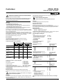
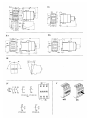
SchÂtz
3TF34, 3TF35
DIN VDE 0660, IEC 60947
Betriebsanleitung
aaaaaa
aaaaaaaaaa
aaaaaaaaaa
aaaaaaaa
aaaaaa
!
Bestell>Nr.: 3ZX1012>0TF02>1AA2
Eingeschrßnkter BerÂhrungsschutz
Schutzart IP 20 nach IEC 60529;
Fingersicher nach DIN VDE 0106, Teil 100
Inbetriebsetzung und Wartung nur durch Fachpersonal.
Beachten Sie die Betriebsanleitung!
Gefßhrliche elektrische Spannung
Vor Beginn der Arbeiten Gerßt spannungsfrei schalten!
Reinigung
Staubablagerungen entfernen (absaugen).
Hilfsschalterblock
Montage
Ma˚bilder (Ma˚e in mm) siehe
Wechselstrombetßtigung Bild I a, b
> Bild Ib 3TF3470/3570 mit unl‘sbar aufgesetzten Hilfsschalterbl‘cken
Gleichstrombetßtigung Bild II a, b
> Bild IIb 3TF3470/3570 mit unl‘sbar aufgesetzten Hilfsschalterbl‘cken
Mindestabstand zu geerdeten Bauteilen: 6 mm
Schnappbefestigung auf Hutschiene 35!mm nach DIN EN!50!022 oder
Schraubbefestigung auf ebener Flßche mit 2 Schrauben M4. Bei
Schraubbefestigung stets Scheiben und Federringe beilegen.
Bei der Montage SchÂtze abdecken, wenn Fremdk‘rper (z.B. Bohr>
spßne) auf die Gerßte gelangen k‘nnen. Bei Verschmutzungsgefahr,
starkem Staubanfall oder aggressiver Atmosphßre SchÂtze in Gehßuse
einbauen.
Zulßssige Einbaulagen siehe Bild III.
Anschlu˚
Die Anschlu˚schrauben sind fÂr Maschinenschrauber geeignet.
Klingenbreite des Schraubendrehers: 5 ... 6 mm
Bitte auch nicht benutzte Anschlu˚schrauben festziehen.
eindrßhtig [mm2]
1
feindrßhtig [mm2]
ohne AderendhÂlse
feindrßhtig [mm2]
mit AderendhÂlse
mehrdrßhtig [mm2]
... 16
beide Klemmstellen
angeschlossen
... 16
max. 16
max. 16
2,5 ... 16
1,5 ... 16
max. 10
max. 16
1
1
max. 10
max. 16
... 16
2,5 ... 25
AWG>Leitungen,
14 ... 3
ein> und mehrdrßhtig
Stiftkabelschuh [mm2] 1 ... 6
gemß˚ DIN 46231
Anziehdrehmoment
1
... 16
Magnetspule
Austausch siehe Bild VII.
> Bild VII a wechselstrombetßtigte Spule
> Bild VII b gleichstrombetßtigte Spule
Auf saubere Magnetpolflßchen achten; zur Reinigung keine fettl‘senden
Mittel verwenden und nicht mit scharfen Gegenstßnden kratzen!
Technische Daten
Gewicht
> Wechselstromantrieb
> Gleichstromantrieb
zulßssige Umgebungstemperatur
> Betrieb
> Lagerung
> 25 ...+55 ∞C
> 50 ...+80 ∞C
Bemessungsisolationsspannung Ui
AC 690 V
Bemessungsbetriebsstrom Ie/AC>1 (55 ∞C) A 55
> 230 V
> 240 V
> 400 V
> 415 V
> 500 V
> 690 V
1,5 ... 25
max. 10
max. 25
Kurzschlu˚schutz:
max. 6
max. 3
Art des Schutzes nach
DIN VDE 0660 Teil 102 A/IEC 60947>4
1
max. 6
max. 6
2,5 ... 3,0 Nm/22 ... 26,5 lb.in
Bemessungsmotor>
leistung PN/AC>3
Bemessungsbetriebsspannung AC
16 ... 3
... 6
ca. 640 g
ca. 1210 g
Hauptstromkreis
Zulßssige Querschnitte fÂr Hauptleiter:
eine Klemmstelle
angeschlossen
Austausch siehe Bild VI.
Max. Anzahl der Hilfsschalterbl‘cke beim 3TF3411/3511> ..:
Im Arbeitsbereich von 0,85 > 1,1¥US k‘nnen frontal ein pneumatisches
Zeitrelais oder maximal 2 Hilfsschalterbl‘cke aufgeschnappt werden.
> Zuordnungsart 1
> Zuordnungsart 2
> schwei˚frei IK<100¥Ie
> schwei˚frei IKf100¥Ie
kW
kW
kW
kW
kW
kW
3TF34
3TF35
8,5
9
15
17
21
23
11
12
18,5
20
25
23
Sicherungseinsßtze
Betriebsklasse gL (gG)
A
A
A
A
80
63
25
25
A
A
A
A
Bemessungsbetriebs>
strom Ie/AC>15/AC>11
5,6
3,8
2,5
1,8
A
A
A
A
A
A
Bemessungsbetriebs>
strom Ie/DC>13/DC>11
10
4,6
0,8
0,2
0,11
0,08
A
A
16
10
Zulßssige Querschnitte fÂr Hilfsleiter:
2¥0,5 ... 1 mm2
2¥1 ... 2,5 mm2
feindrßhtig, mit AderendhÂlse
2¥0,5 ... 1 mm2
2¥0,75 ... 2,5 mm2
AWG>Leitungen
2¥AWG 18 ... 12
Anziehdrehmoment Grundgerßt
0,8 ... 1,4 Nm/7 ... 12 lb.in
Anziehdrehmoment Hilfsschalterblock 0,8 ... 1,1 Nm/7 ... 10 lb.in
Gerßteschaltplan und Lage der Anschlu˚klemmen siehe Bild IV.
* mit Anzeige
eindrßhtig
Betrieb
Beachten Sie die Betßtigungsspannung (siehe Kennzeichnungsschild
der Magnetspule).
Der Schaltzustand des SchÂtzes ist an der Schaltstellungsanzeige er>
kennbar, siehe Bild V.
!
Bei anliegender Netzspannung und Last das SchÂtz nicht durch
NiederdrÂcken der Schaltstellungsanzeige betßtigen!
Instandhaltung
Hilfsstromkreis
Bemessungsbetriebsspannung
> 230 V
> 400 V
> 500 V
> 690 V
Bemessungsbetriebsspannung
> 24 V
> 48 V
> 110 V
> 220 V
> 440 V
> 600 V
Kurzschlu˚schutz:
> Sicherungseinsßtze
NEOZED und DIAZED, gL (gG)
> Leitungsschutzschalter, C>Char.
Austauschbar sind: Magnetspule und einpoliger Hilfsschalter>
block!3TX40. Bestellnummern siehe Katalog NSK und Bild IV.
Um die Betriebssicherheit der SchÂtze zu gewßhrleisten, dÂrfen nur
Original>Ersatzteile verwendet werden!
GWA 4NEB 522 4570>10c
Weitere Angaben und Zubeh‘r siehe Katalog NSK.
1
Contactor
3TF34, 3TF35
DIN VDE 0660, IEC 60947
Instructions
Order No.: 3ZX1012>0TF02>1AA2
aaaaaaaaa
aaaaaaaaa
aaaaaaaaaaaaaa
aaaaaaaaaaaaaa
aaaaaaaaaaaaaa
aaaaaaaaaa
aaaaaaaaaa
Permissible cross>sections for auxiliary conductor:
WARNING:
Solid
HAZARDOUS VOLTAGE
CAN CAUSE ELECTRICAL SHOCK
AND BURNS.
DISCONNECT POWER BEFORE PROCEEDING
WITH ANY WORK ON THIS EQUIPMENT.
Finely stranded, with end sleeve
AWG wires
Tightening torque standard type
Tightening torque auxiliary contact block
2¥0.5 to 1 mm2
2¥1 to 2.5 mm2
2¥0.5 to 1 mm2
2¥0.75 to 2,5 mm2
2¥AWG 18 to 12
0.8 to 1.4 Nm/7 to 12 lb.in
0.8 to 1.1 Nm/7 to 10 lb.in
Use 75 ∞C copper wire only.
For circuit diagram and position of connection terminals see Fig. IV.
*with indicator
Limited protection against contact with live parts
!
Degree of protection IP 20 to IEC 60529
Safe from finger touch to DIN VDE 0106, Part 100
Commissioning and maintenance by qualified personnel only.
Follow the operating instructions.
For circuit diagram (NEMA) see Fig. A.
Operation
Observe operating voltage (see rating plate of magnet coil).
The operating state of the contactor is shown at the position indicator; see
Fig. V.
Installation
!
Snap onto 35 mm standard mounting rail to DIN EN 50 022 or fix on a
plain surface with two M4 screws. With screw mounting, always use
plain washers and spring washers.
Cover the contactors during installation if foreign particles, such as
swarf, can fall onto them. Install contactors in a housing if they are
exposed to dirt, dust or aggressive atmospheres.
For permissible mounting positions see Fig. III.
The terminal screws can be tightened with a power screwdriver.
Screwdriver blade width: 5 to 6 mm
Tighten all terminal screws even if not used.
Permissible cross>sections for main conductor:
Solid [mm2]
1
[mm2],
Finely stranded
without end sleeve
to 16
2.5 to 16
both terminals
connected
1
to 16
max. 16
max. 16
1.5 to 16
max. 10
max. 16
to 16
1
max. 10
max. 16
to 16
Stranded [mm2]
2.5 to 25
1.5 to 25
max. 10
max. 25
AWG wires,
solid and stranded
14 to 3
16 to 3
max. 6
max. 3
Terminal pin [mm2]
in accordance with
DIN 46231
1
1
max. 6
max. 6
2
Only use of original spare parts ensures the operational safety of the
contactors.
HAZARDOUS VOLTAGE
CAN CAUSE ELECTRICAL SHOCK AND BURNS.
Disconnect power before proceeding with any
work on this equipment.
Auxiliary contact block
For replacement see Fig. VI.
Maximum number of auxiliary contact blocks of 3TF3411/3511>..:
A pneumatic time>delay relay or max. 2 auxiliary switches can be snapped
on front for the operating range 0.85 to 1.1 times the switching voltage US.
Magnet coil
For coil replacement see.Fig. VII.
> Fig. VII a a.c. coil
> Fig. VII b d.c. coil
Ensure that the pole faces of the magnet coil are clean. Do not use grease
solvents or sharp objects for cleaning.
Technical Data
Finely stranded [mm2], 1
with end sleeve
Tightening torque
The following components can be replaced: magnet coil and single>pole
auxiliary contact block 3TX40. For Order Nos. see Catalog NSK and Fig. IV.
Cleaning
Remove dust by suction.
Connection
one terminal
connected
Maintenance
aaaaaaaa
aaaaaaaa
aaaaaaaaaaaa
aaaaaaaaaaaa
aaaaaaaaaaaa
aaaaaaaa
aaaaaaaa
For dimension drawings (dimensions in mm) see
a.c. operation Fig. Ia,b
> Fig. Ib 3TF3470/3570 with non>detachable auxiliary contact blocks
d.c. operation Fig. IIa,b
> Fig. IIb 3TF3470/3570 with non>detachable auxiliary contact blocks
Minimum clearances from earthed parts: 6 mm
When the system voltage is applied and the load is connected, do
not operate the contactor by pressing down the position indicator.
to 6
to 6
2.5 to 3.0 Nm/22 to 26.5 lb.in
Weight
> a.c. operated
> d.c. operated
Permissible ambient temperature
> Operation
> Storage
Main circuit
Rated insulation voltage Ui
Rated operational current
Ie/AC>1 (55 ∞C)
approx. 640 g
approx. 1210 g
> 25 to+55 ∞C
> 50 to+80 ∞C
AC 690 V
A 55
Motor rating PN/AC>3
Rated operational voltage AC
> 230 V
> 240 V
> 400 V
> 415 V
> 500 V
> 690 V
kW
kW
kW
kW
kW
kW
3TF34
3TF35
8,5
9
15
17
21
23
11
12
18.5
20
25
23
Short>circuit protection:
> Fuse>links
NEOZED and DIAZED, gL (gG)
> Circuit>breaker, C>char.
16
A
10
A
Fig. A
ratings)
AC 600 V
Rated output of three>phase
motors at 60 Hz
3TF34..>....1
3TF34 3TF35
NEMA/EEMAC
SIZE 1
Continuous current
(open and enclosed type)
> 200 V
> 230 V
> 460 V
> 575 V
A
27
42
L1
CIRCUIT
PROTECTIVE
DEVICE
L2
L3
(IF USED)
7.5
7.5
10
10
10
10
25
25
10
10
25
25
T1
OLR
T2
M
OLR
T3
(1)
H1
X1
STOP
3
PHASE
MOTOR
FUSE
X2
SEC.
FUSE
Suitable for use on a circuit capable of delivering not more than
5000!rms symmetrical amperes, 600 V max.
START
(2)
44
Short>circuit protection:
(3)
43
M
95
M
A1
OLR
96
A2
Fuse>links
Duty class gL (gG)
Degree of protection to
DIN VDE 0660/part 102 A/IEC 60947>4 **
> Assignment type 1
> Assignment type 2
> non>welding IK< 100¥Ie
> Non>welding IKf100¥Ie
OLR
M
PRI.
H4
hp
hp
hp
hp
M
FUSE
45
IF CPT IS
USED
Horsepower Ratings (
and
Rated insulation voltage Ui
A
A
A
A
80
63
25
25
2 WIRE CONTROL (IF USED)
Auxiliary circuit
Rated operational
current Ie/AC>15/AC>11
Rated operational voltage
> 230 V
> 400 V
> 500 V
> 690 V
A
A
A
A
Rated operational
current Ie/DC>13/DC>11
Rated operational voltage
> 24 V
> 48 V
> 110 V
> 220 V
> 440 V
> 600 V
5.6
3.8
2.5
1.8
A
A
A
A
A
A
10
4.6
0.8
0.2
0.11
0.08
For further data and accessories see Catalog NSK.
** Footnote:
According to IEC 60947/VDE 0660, the types of protection mean:
∫Assignment type 1∫: Short circuits can cause damage to the contactors making replacement of the equipment necessary.
∫Assignment type 2∫ : Easily separable contact welding but no other damage.
3
Contactor
3TF34, 3TF35
DIN VDE 0660, IEC 60947
Instrucciones de servicio
Protecci–n parcial contra contactos involuntarios
°Para garantizar la seguridad operativa de los contactores solo deber¢n
utilizarse repuestos originales!
Grado de protecci–n IP 20 seg‡n IEC 60529
protegido contra contacto con los dedos seg‡n DIN VDE 0106, parte 100
Puesta en servicio y mantenimiento solo por personal cualificado.
°Observar las instrucciones de servicio !
aaaaaaaa
aaaaaaaaaaaaa
aaaaaaaaaaaaa
aaaaaaaaaa
aaaaaaaa
!
NÎ de pedido: 3ZX1012>0TF02>1AA2
Montaje
Limpieza
Retirar los dep–sitos de polvo (°aspirarlos!)
Tensi–n el±ctrica peligrosa
antes de comenzar el trabajo
°desconectar el aparato!
Croquis acotados (dimensiones en mm): v.
accionado por corriente alterna fig. I a,b
> fig. Ib 3TF3470/3570 con bloques de contactos auxiliares no desmont.
accionado por corriente continua fig. II a,b
> fig. IIb 3TF3470/3570 con bloques de contactos auxiliares no desmont.
Distancias mønimas a las partes puestas a tierra: 6 mm
Enganche sobre carril en ] de 35 mm seg‡n DIN EN 50 022 – fijaci–n
sobre superficie plana mediante 2 tornillos M4; en este caso utilizar
siempre arandela plana y arandela el¢stica.
Si durante el montaje hay peligro de caøda de cuerpos extraÃos (p.ej.
virutas), tapar los contactores. En caso de peligro de ensuciamiento,
dep–sitos apreciables de polvo o atm–sfera agresiva, montar los contac>
tores en una caja.
Bloque de contactos auxiliares
Sustituci–n, v. fig. VI.
Cantidad m¢x. de bloques de contactos auxiliares en el 3TF3411/3511>..:
Cantidad m¢x. de bloques de contactos auxiliares en el 3TF3411/3511>..:
En el campo de trabajo de 0,85 a 1,1¥US, se pueden aplicar frontalmente un
rel± de tiempo neum¢tico o m¢x. 2 interruptores auxiliares.
Bobina
Sustituci–n, v. fig. VII.
> fig. VII a bobina de corriente alterna
> fig. VII b bobina de corriente continua
°Atender a que est±n limpias las superficies polares; para limpiar no utilizar
productos disolventes de grasas, y no rascar con objetos agudos!
Posiciones de montaje admisibles: v. fig. III.
Datos t±cnicos
Conexi–n
Peso
> accionado por corriente alterna
> accionado por corriente continua
Temperatura ambiente admisible
> operaci–n
> almacenamiento
Circuito principal
Tensi–n asignada de aislamiento Ui
Corriente asignada de servicio
Ie/AC>1 (55 ∞C)
Los tornillos de conexi–n son adecuados para destornilladores mecani>
zados.
Ancho de la hoja del destornillador: 5 a 6 mm
Apretar tambi±n los tornillos de conexi–n no utilizados.
Secciones admisibles para el conductor principal
se ocupa un lado del
borne
se ocupan ambos lados
del borne
aprox. 640 g
aprox. 1210 g
> 25 a+55 ∞C
> 50 a+80 ∞C
AC 690 V
A 55
Potencia asignada del
motor PN/AC>3
Tensi–n asignada de servicio AC
Monofilar [mm2]
1
a 16
max. 16
max. 16
Flexible [mm2],
sin vaina terminal
2,5 a 16
1,5 a 16
max. 10
max. 16
Flexible [mm2],
con vaina terminal
1
1
a 16
max. 10
max. 16
Multifilar [mm2]
2,5 a 25
1,5 a 25
max. 10
max. 25
Protecci–n contra cortocircuitos:
Cables calibre AWG,
mono y multifilares
14 a 3
16 a 3
max. 6
max. 3
Tipo de protecci–n seg‡n
DIN VDE 0660 parte 102 A/IEC 60947>4
Terminal recto [mm2]
seg‡n DIN 46231
Par de apriete
1
1
max. 6
max. 6
> tipo 1
> tipo 2
> sin soldadura IK<100¥Ie
> sin soldadura IKf100¥Ie
Circuito auxiliar
a 16
a 16
a 6
1
a 6
2,5 a 3,0 Nm/22 a 26,5 lb.in
Secciones admisibles para conductores auxiliares
Monofilar
2¥ 0,5 a 1 mm2
2¥ 1 a 2,5 mm2
Flexible, con vaina terminal
2¥ 0,5 a 1 mm2
2¥0,75 a 2,5 mm2
Cables calibre AWG
2¥ AWG 18 a 12
Par de apriete aparato b¢sico
0,8 a 1,4 Nm/7 a 12 lb.in
Par de apriete bloque de contactos aux.
0,8 a 1,1 Nm/7 a 10 lb.in
Esquema y situaci–n de los bornes de conexi–n, v. fig. IV.
* con indicador
Operaci–n
Observar la tensi–n de operaci–n de la bobina (figura en la placa
identificadora de la bobina).
El estado de maniobra del contactor puede apreciarse en el indicador
correspondiente, v. fig. V.
!
°Estando aplicada la tensi–n de red y la carga no accionar el
contactor apretando el indicador de posici–n de maniobra!
Reparaci–n
Piezas reemplazables: bobina y bloque de contactos auxiliares unipolar
3TX40. N‡meros de pedido: v. cat¢logo NSK y fig. IV.
4
> 230 V
> 240 V
> 400 V
> 415 V
> 500 V
> 690 V
kW
kW
kW
kW
kW
kW
A
A
A
A
A
A
A
A
Tensi–n asignada de servicio
> 24 V
> 48 V
> 110 V
> 220 V
> 440 V
> 600 V
Protecci–n contra cortocircuitos:
3TF35
11
12
18,5
20
25
23
Cartuchos fusibles
Clase de servicio
gL (gG)
Tensi–n asignada de servicio
> 230 V
> 400 V
> 500 V
> 690 V
3TF34
8,5
9
15
17
21
23
A
A
A
A
A
A
> Cartuchos fusibles
NEOZED y DIAZED, gL (gG)
A
> Interruptor autom¢tico,
caracterøstica C
A
Para m¢s datos y accesorios, v. cat¢logo NSK.
80
63
25
25
Corriente asignada de
servicio
Ie/AC>15/AC>11
5,6
3,8
2,5
1,8
Corriente asignada de
servicio
Ie/DC>13/DC>11
10
4,6
0,8
0,2
0,11
0,08
16
10
Contacteur
3TF34, 3TF35
DIN VDE 0660, CEI 60947
Instructions de service
Protection restreinte contre les contacts directs
Degr± de protection IP 20 selon CEI 60529
Satisfait ° lπessai au doigt dπ±preuve sp±cifi± par DIN VDE 0106, partie 100
Ne confier la mise en service et lπentretien quπ° du personnel qualifi±.
Respecter les instructions de service.
Afin de garantir la s±curit± dπemploi des contacteurs, nπutiliser que des
pi∞ces de rechange dπorigine.
aaaaaa
aaaaaaaaaa
aaaaaaaaaa
aaaaaaaa
aaaaaa
!
N∞ de r±f. : 3ZX1012>0TF02>1AA2
Tension ±lectrique dangereuse
Avant toute intervention, mettre lπappareil hors tension!
Nettoyage
Enlever les d±p—ts de poussi∞re (° lπaspirateur).
Montage
Encombrements (cotes en mm), voir
° commande par courant alternatif Fig. I a,b
> Fig. Ib 3TF3470/3570 avec blocs de contacts aux. rapport±s ° demeure
° commande par courant continu Fig. II a,b
> Fig. IIb 3TF3470/3570 avec blocs de contacts aux. rapport±s ° demeure
Distances minimales aux parties mises ° la terre: 6 mm
Encliquetage sur profil± chapeau 35 mm selon DIN EN 50 022 ou fixation
par 2 vis M4 sur surface plane. Pour la fixation par vis pr±voir des rondelles
plates et de rondelles Grower.
Lors du montage, recouvrir le contacteur si des corps ±trangers (par ex.
copeaux de per≠age) peuvent tomber sur ce dernier. Lorsquπil y a risque
dπencrassement, production importante de poussi∞re ou pr±sence
dπatmosph∞re corrosive, monter le contacteur dans un bo¿tier.
Position admissible de montage, voir Fig. III.
Raccordement
Les vis des bornes peuvent ≤tre viss±es ° lπaide dπune visseuse.
Largeur de lπempreinte : 5 ° 6 mm
Serrer toutes les vis (±galement les vis de bornes non affect±es).
Conducteur principal : sections admissibles
1 conducteur par borne
2 conducteurs par borne
Bloc de contacts auxiliaires
Remplacement, voir Fig. VI.
Nombre max. de blocs de contacts aux. pour 3TF3411/3511>..:
Dans la plage de tension 0,85 ° 1,1 US, un relais temporis± pneumatique ou
max. 2 blocs de contacts auxiliaires peuvent ≤tre encliquet±s en face avant.
Bobine magn±tique
Remplacement, voir Fig. VII.
> Fig. VII a bobine courant alternatif
> Fig. VII b bobine courant continu
Sπassurer que les surfaces polaires sont propres ; ne pas utiliser de produit
dissolvant la graisse et ne pas gratter avec un objet pointu.
Caract±ristiques techniques
Poids
> ° commande par courant alternatif
> ° commande par courant continu
Temp±rature ambiante admissible
> en fonctionnement
> au stockage
Circuit principal
Tension assign±e dπisolement Ui
Courant assign± dπemploi
Ie/AC>1 (55 ∞C)
env. 640 g
env. 1210 g
> 25 °+55 ∞C
> 50 °+80 ∞C
AC 690 V
A 55
Puissance assign±e du
moteur PN/AC>3
Tension assign±e dπemploi
(alternatif)
Ame massive [mm2]
1
° 16
Ame souple [mm2] ,
sans cosse
2,5 ° 16
Ame souple [mm2],
avec cosse
1
Ame rigide c£bl±e
[mm2]
1
° 16
max. 16
max. 16
1,5 ° 16
max. 10
max. 16
° 16
max. 10
max. 16
2,5 ° 25
1,5 ° 25
max. 10
max. 25
Conducteurs AWG
£me rigide c£bl±e/
massive
14 ° 3
16 ° 3
max. 6
max. 3
Cosse ° tige [mm2]
selon DIN 46231
Couple de serrage
1
° 16
° 6
1
1
° 6
max. 6
max. 6
2,5 ° 3,0 Nm/22 ° 26,5 lb.in
> 230 V
> 240 V
> 400 V
> 415 V
> 500 V
> 690 V
kW
kW
kW
kW
kW
kW
Protection contre les courts>circuits :
Type de protection selon
DIN VDE 0660 Partie 102 A/CEI 60947>4
> type 1
> type 2
> sans soudure IK<100¥Ie
> sans soudure IKf100¥Ie
Circuit auxiliaire
2¥ 0,5 ° 1 mm2
2¥ 1 ° 2,5 mm2
Ame souple avec embout
2¥ 0,5 ° 1 mm2
2¥ 0,75 ° 2,5 mm2
Conducteurs AWG
2¥ AWG 18 ° 12
Couple de serrage appareil base
0,8 ° 1,4 Nm/7 ° 12 lb.in
Couple de serrage bloc de contacts auxiliaires
0,8 ° 1,1 Nm/7 ° 10 lb.in
Sch±ma ±lectrique de lπappareil et position des bornes, voir Fig. IV.
* avec signalisation
A
A
A
A
Fonctionnement
Respecter la tension dπalimentation (voir plaquette de la bobine).
La position du contacteur est affich±e par un indicateur de position, voir
Fig. V.
!
Ne pas man˙uvrer le contacteur sous tension et en charge en
enfon≠ant lπindicateur de position!
Entretien
Les ±l±ments suivants peuvent ≤tre remplac±s : bobine magn±tique et bloc
de contacts auxiliares unipolaire 3TX40. R±f±rence de commandes, voir
Catalogue NSK et Fig. IV.
Protection contre les courts>circuits :
> Cartouches fusibles
NEOZED et DIAZED, gL (gG)
> Protection de ligne par
petit disjoncteur, ° caract. C
80
63
25
25
A
A
A
A
A
A
A
16
A
10
A
A
A
A
Tension assign±e dπemploi
> 24 V
> 48 V
> 110 V
> 220 V
> 440 V
> 600 V
11
12
18,5
20
25
23
Courant assign±
dπemploi
Ie/AC>15/AC>11
5,6
3,8
2,5
1,8
Courant assign±
dπemploi
Ie/DC>13/DC>11
10
4,6
0,8
0,2
0,11
0,08
Tension assign±e dπemploi
> 230 V
> 400 V
> 500 V
> 690 V
3TF35
8,5
9
15
17
21
23
Cartouches fusibles
Classe de service
gL (gG)
Conducteurs auxiliaires : sections admissibles
Ame massive
3TF34
Pour de plus amples informations et pour les accessoires, voir Catalogue
NSK.
5
Contattore
3TF34, 3TF35
DIN VDE 0660, IEC 60947
Istruzioni
Protezione limitata contro contatti accidentali
Grado di protezione IP 20 sec. IEC 60529
protetto contro contatti con le dita sec. DIN VDE 0106, Parte 100
Messa in servizio e manutenzione da eseguire solamente da parte di
personale specializzato.
Attenersi alle istruzioni di servizio!
Montaggio
Per i disegni quotati (dimensioni in mm) v.
azionato in corrente alternata fig. I a,b
> fig. I b 3TF3470/3570 con blocchetti di contatti ausiliari fissi
azionato in corrente continua fig. II a,b
> fig. II b 3TF3470/3570 con blocchetti di contatti ausiliari fissi
Distanze minime dalle parti collegate a terra: 6 mm
Il fissaggio avviene a scatto su profilato ad omega da 35 mm sec. DIN
EN!50 022 oppure a vite su superficie piana, mediante due viti M4. Nel
caso di fissaggio a vite frapporre sempre rondelle semplici ed elastiche.
Durante il montaggio, coprire il contattore se si teme che corpi estranei
(p.e. trucioli di trapanatura) possano penetrarvi. Si vi ∞ pericolo di
sporco, di polvere o di agenti chimici aggressivi, montare l'apparecchio
in una custodia.
In fig. III sono indicate le posizioni d'installazione consentite.
Collegamenti
Le viti degli attacchi sono adatte per avvitatrici.
Diametro della punta del trapano: 5 ... 6 mm.
Si raccomanda di serrare anche le viti non utilizzate.
Sezioni ammissibili per i conduttori principali:
Attacco ad un morsetto
Attacco ai due morsetti
Per garantire la sicurezza di funzionamento dei contattori, vanno impiegati
solo pezzi di ricambio originali.
aaaaaaa
aaaaaaaaaaa
aaaaaaaaaaa
aaaaaaa
aaaaaa
!
No. d 'ordinaz.: 3ZX1012>0TF02>1AA2
Tensione elettrica pericolosa
Prima di eseguire eventuali lavori, disinserire l'apparecchio!
Pulizia
Togliere la polvere depositatasi (aspirapolvere!)
Blocchetto contatti ausiliari
Per la sostituzione v. fig. VI.
Numero massimo di blocchetti di contatti ausiliari per il 3TF3411/3511>..:
Nel campo di lavoro da 0,85 a 1,1 US si possono aprire a scatto frontalmente
un rel∞ a tempo pneumatico o max. 2 blocchetti di contatti ausiliari.
Bobina
Per la sostituzione v. fig. VII.
> fig. VII a bobina di corrente alternata
> fig. VII b bobina di corrente continua
Si abbia cura che la superficie dei poli sia sempre pulita; per pulirla non si
usino solventi di grassi e si eviti di grattarla con oggetti accuminati.
Dati tecnici
Peso
> azionato in corrente alternata
> azionato in corrente continua
Temperatura ambiente consentita
> funzionamento
> magazzinaggio
Circuito principale
Tensione nominale d'isolamento Ui
Corrente nominale d'impiego
Ie/AC>1 (55 ∞C)
ca. 640 g
ca. 1210 g
> 25 ...+55 ∞C
> 50 ...+80 ∞C
AC 690 V
A 55
Potenza nominale del
motore PN/AC>3
Tensione nominale d'impiego AC
A filo unico [mm2]
1
A corda flessibile
[mm2], senza boccola
terminale
... 16
max. 16
max. 16
2,5 ... 16
1,5 ... 16
max. 10
max. 16
A corda flessibile
[mm2], con boccola
terminale
1
1
... 16
max. 10
max. 16
A corda rigida [mm2]
2,5 ... 25
1,5 ... 25
max. 10
max. 25
Conduttori AWG,
a filo unico e a corda
rigida
Capocorda a spina
[mm2] sec. DIN 46231
14 ... 3
16 ... 3
max. 6
max. 3
1
1
max. 6
max. 6
Coppia di serraggio
... 16
... 16
... 6
1
... 6
2,5 ... 3,0 Nm/22 ... 26,5 lb.in
Sezioni ammissibili per i conduttori ausiliari:
A filo unico
2¥ 0,5 ... 1 mm2
2¥ 1 ... 2,5 mm2
A corda flessibile
con boccola terminale
2¥0,5 ... 1 mm2
2¥ 0,75 ... 2,5 mm2
Conduttori AWG
2¥ AWG 18 ... 12
Coppia di serraggio apparecchio base
0,8 ... 1,4 Nm/7 ... 12 lb.in
Coppia di serraggio blocchetto contatti aus. 0,8 ... 1,1 Nm/7 ... 10 lb.in
Per lo schema dell'apparecchio e la posizione dei morsetti di attacco,
v.!fig. IV. * con segnalazione
Funzionamento
Si faccia attenzione alla tensione di azionamento (v. la targhetta dei
dati sulla bobina elettromagnetica).
La posizione di manovra del contattore ∞ rilevabile dall'apposito
indicatore, v. fig. V.
!
Il contattore, quando si trova sotto tensione e sotto carico, non
dev'essere azionato premendo l'indicatore della posizione di
manovra!
Manutenzione
Si possono sostituire: la bobina elettromagnetica ed il blocchetto dei
contatti ausiliari unipolare 3TX40. Per i numeri d'ordinazione v. il
catalogo NSK e fig. IV.
6
> 230 V
> 240 V
> 400 V
> 415 V
> 500 V
> 690 V
kW
kW
kW
kW
kW
kW
Protezione contro corti circuiti:
Tipo di protezione sec.
DIN VDE 0660 Parte 102 A/IEC 60947>4
> tipo 1
> tipo 2
> esente da saldature IK<100¥Ie
> esente da saldature IKf100¥Ie
3TF34
3TF35
8,5
9
15
17
21
23
11
12
18,5
20
25
23
Cartucce di fusibili
Clase di esercizio
gL (gG)
A
A
A
A
80
63
25
25
Circuito ausiliario
Corrente nominale
d'impiego
Ie/AC>15/AC>11
Tensione nominale d'impiego
> 230 V
> 400 V
> 500 V
> 690 V
A
A
A
A
5,6
3,8
2,5
1,8
Corrente nominale
d'impiego
Ie/DC>13/DC>11
A
A
A
A
A
A
10
4,6
0,8
0,2
0,11
0,08
A
16
A
10
Tensione nominale d'impiego
> 24 V
> 48 V
> 110 V
> 220 V
> 440 V
> 600 V
Protezione contro corti circuiti:
> cartucce di fusibili
NEOZED e DIAZED, gL (gG)
> interruttore di protezione
dei conduttori, C>Char.
Per altri dati e per gli accessori v. catalogo NSK.
Kontaktor
3TF34, 3TF35
DIN VDE 0660, IEC 60947
Driftsinstruktion
F‘r att sßkerstßlla kontaktorernas driftsßkerhet f®r bara original>reservdelar
anvßndas.
Begrßnsat ber‘ringsskydd
aaaaaa
aaaaaaaaaa
aaaaaaaaaa
aaaaaaaa
aaaaaa
!
Ordernr.: 3ZX1012>0TF02>1AA2
Skyddsform (kapslingsklass) IP 20 enl. IEC 60529
Ber‘ringssßker enl. DIN VDE 0106, Del 100
Idrifttagning och underh®ll f®r enbart utf‘ras av fackpersonal.
F‘lj driftsinstruktionen!
Reng‘ring
Montering
Hjßlpkopplarblock
Farlig elektrisk spßnning
Koppla fr®n str‘mmen innan arbetet p®b‘rjas!
Avlßgsna dammavlagringar (rensugning!)
M®ttskisser (m®tt i mm), se
vßxelstr‘msman‘vrerad Fig. I a,b
> Fig. I b 3TF3470/3570 med fast monterade hjßlpkopplarblock
likstr‘msman‘vrerad Fig. II a,b
> Fig. II b 3TF3470/3570 med fast monterade hjßlpkopplarblock
Minimiavst®nd till jordade detaljer: 6 mm
Snßppfßste p® 35 mm normskena enl. DIN EN 50 022 eller skruvfßste p®
jßmn yta med tv® skruvar M4. Anvßnd alltid brickor och fjßderbrickor
med skruvfßstet.
Tßck ‘ver kontaktorerna vid monteringen, om det finns risk att
partiklar kan trßnga in i dem (borrsp®n o. dyl.). Montera kontaktorerna
i kßpor om det finns risk f‘r stark nedsmutsning, dammbildning eller
aggressiv atmosfßr.
Till®tna monteringslßgen enl. Fig. III.
Utbyte enl. Fig. VI.
St‘rsta antal hjßlpkopplarblock vid 3TF3411/3511>..:
I arbetsomr®det 0,85 > 1,1¥US kan man p® framsidan snßppa p® ett tidrelß
eller max. 2 hjßlpkopplare.
Magnetspole
Byte enl. Fig. VII.
> Fig. VII a vßxelstr‘mspole
> Fig. VII b likstr‘mspole
Se till att spolens ytor ßr rena. Anvßnd ej fettl‘sande medel vid reng‘ringen
och skrapa ej med skarpa f‘rem®l.
Tekniska data
Anslutningsskruvarna ßr lßmpade f‘r ®tdragning med motordriven
skruvmejsel.
Skruvmejselns bredd: 5 ... 6 mm
Dra ßven ®t outnyttjade fßstskruvar!
Vikt
> vßxelstr‘msman‘vrerad
> likstr‘msman‘vrerad
Till®ten omgivningstemperatur
> drift
> lagring
Till®tna areor f‘r huvudledare:
Huvudstr‘mkrets
Anslutning
Ansluten till en
kontaktpunkt
Ansluten till b®da
kontaktpunkterna
Mßrkisolationsspßnning Ui
Mßrkdriftstr‘m Ie/AC>1 (55 ∞C)
c:a 640 g
c:a 1210 g
> 25 ...+55 ∞C
> 50 ...+80 ∞C
AC 690 V
A 55
Motorns mßrkeffekt
PN/AC>3
Mßrkdriftspßnning AC
Entr®dig [mm2]
1
... 16
1
... 16
max. 16
max. 16
> 230 V
> 240 V
> 400 V
> 415 V
> 500 V
> 690 V
Fintr®dig (mm2),
utan tr®dßndhylsa
2,5 ... 16
1,5 ... 16
max. 10
max. 16
Fintr®dig (mm2),
med tr®dßndhylsa
1
1
... 16
max. 10
max. 16
Flertr®dig (mm2)
2,5 ... 25
1,5 ... 25
max. 10
max. 25
Kortslutningsskydd:
AWG>ledningar,
en> och flertr®diga
14 ... 3
16 ... 3
max. 6
max. 3
Typ av skydd enl.
DIN VDE 0660 Del 102 A/IEC 60947>4
Stiftkabelsko (mm2)
enl. DIN 46231
1
1
max. 6
max. 6
... 16
... 6
(tdragningsmoment
... 6
2,5 ... 3,0 Nm/22 ... 26,5 lb.in
Till®tna areor f‘r hjßlpledare:
2¥ 0,5 ... 1 mm2
2¥ 1 ... 2,5 mm2
Fintr®dig med ßndhylsa
2¥ 0,5 ... 1 mm2
2¥0,75 ... 2,5 mm2
AWG>ledningar
2¥ AWG 18 ... 12
(tdragningsmoment basenhet
0,8 ... 1,4 Nm/7 ... 12 lb.in
(tdragningsmoment hjßlpkopplarblock 0,8 ... 1,1 Nm/7 ... 10 lb.in
Apparatschema och konkaktklßmmornas lßge enl. Fig. IV.
* med indikering
Entr®dig
Drift
Ge akt p® man‘verspßnningen (se beteckningsskylten p® magnet>
spolen).
Kontaktorns kopplingsstatus framg®r av statusindikeringen, se Fig. V.
!
Man‘vrera inte kontaktorn genom att trycka ned status>
indikeringen med p®lagd nßtspßnning och ansluten belastning.
> Typ 1
> Typ 2
> Svetsfri IK<100¥Ie
> Svetsfri IKf100¥Ie
kW
kW
kW
kW
kW
kW
3TF34
3TF35
8,5
9
15
17
21
23
11
12
18,5
20
25
23
Sßkringsinsatser
Driftsklass gL (gG)
A
A
A
A
80
63
25
25
A
A
A
A
Mßrkdriftstr‘m
Ie/AC>15/AC>11
5,6
3,8
2,5
1,8
A
A
A
A
A
A
Mßrkdriftstr‘m
Ie/DC>13/DC>11
10
4,6
0,8
0,2
0,11
0,08
A
A
16
10
Man‘verstr‘mkrets
Mßrkisolationsspßnning
> 230 V
> 400 V
> 500 V
> 690 V
Mßrkisolationsspßnning
> 24 V
> 48 V
> 110 V
> 220 V
> 440 V
> 600 V
Kortslutningsskydd:
> Sßkringsinsatser
NEOZED och DIAZED, gL (gG)
> Ledningsskyddsbrytare, C>kar.
Underh®ll
Utbytbara komponenter: magnetspole, 1>polig hjßlpkopplarblock
3TX40. Ordernr. se katalog NSK och Fig. IV.
Ytterligare uppgifter, se katalog NSK.
7