1
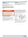
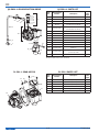
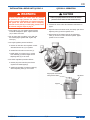
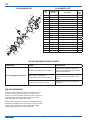
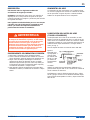
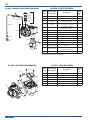
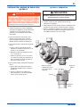
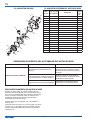
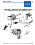
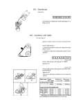
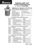
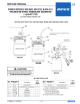
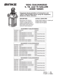
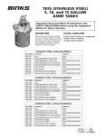
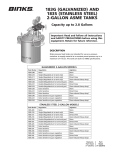
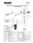
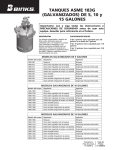
SERVICE MANUAL
EN
QS-5001-1 AIR MOTOR DRIVE
77-2992-R1.0
1/8
EN
In this part sheet, the words WARNING, CAUTION and NOTE are used to
emphasize important safety information as follows:
!
WARNING
Hazards or unsafe practices which
could result in severe personal
injury, death or substantial property
damage.
NOTE
! Caution
Hazards or unsafe practices which
could result in minor personal injury,
product or property damage.
!
Important installation, operation or
maintenance information.
WARNING
Read the following warnings before using this equipment.
Read the Manual
Before operating finishing equipment, read and understand all
safety, operation and maintenance information provided in the
operation manual.
Projectile Hazard
You may be injured by venting liquids or gases that are released
under pressure, or flying debris.
Operator Training
All personnel must be trained before operating finishing
equipment.
Pinch Point Hazard
Moving parts can crush and cut. Pinch points are basically any
areas where there are moving parts.
Equipment Misuse Hazard
Equipment misuse can cause the equipment to rupture,
malfunction, or start unexpectedly and result in serious injury.
Static Charge
Fluid may develop a static charge that must be dissipated through
proper grounding of the equipment, objects to be sprayed and all
other electrically conductive objects in the dispensing area. Improper
grounding or sparks can cause a hazardous condition and result in
fire, explosion or electric shock and other serious injury.
LOCK OUT / TAG-OUT
Failure to de-energize, disconnect, lock out and tag-out all power
sources before performing equipment maintenance could cause
serious injury or death.
Wear Respirator
Toxic fumes can cause serious injury or death if inhaled.
Wear a respirator as recommended by the fluid and solvent
manufacturer’s Material Safety Data Sheet.
AUTOMATIC EQUIPMENT
Automatic equipment may start suddenly without warning.
Toxic Fluid & Fumes
Hazardous fluid or toxic fumes can cause serious injury or death if
splashed in the eyes or on the skin, inhaled, injected or
swallowed. LEARN and KNOW the specific hazards or the fluids
you are using.
PRESSURE RELIEF PROCEDURE
Always follow the pressure relief procedure in the equipment
instruction manual.
FIRE AND EXPLOSION HAZARD
Improper equipment grounding, poor ventilation, open flame or
sparks can cause a hazardous condition and result in fire or
explosion and serious injury.
Keep Equipment Guards in Place
Do not operate the equipment if the safety devices have been
removed.
MEDICAL ALERT
Any injury caused by high pressure liquid can be serious. If you
are injured or even suspect an injury:
Know Where and How to Shut Off the Equipment
in Case of an Emergency
• Go to an emergency room immediately.
• Tell the doctor you suspect an injection injury.
•S
how the doctor this medical information or the medical alert
card provided with your airless spray equipment.
Wear Safety Glasses
Failure to wear safety glasses with side shields could result in
serious eye injury or blindness.
•T
ell the doctor what kind of fluid you were spraying or
dispensing.
GET IMMEDIATE MEDICAL ATTENTION
To prevent contact with the fluid, please note the following:
Inspect the Equipment Daily
Inspect the equipment for worn or broken parts on a daily basis.
Do not operate the equipment if you are uncertain about its
condition.
• Never point the gun/valve at anyone or any part of the body.
• Never put hand or fingers over the spray tip.
•N
ever attempt to stop or deflect fluid leaks with your hand,
body, glove or rag.
Never Modify the Equipment
Do not modify the equipment unless the manufacturer provides
written approval.
• Always have the tip guard on the spray gun before spraying.
•A
lways ensure that the gun trigger safety operates before
spraying.
Noise Hazard
You may be injured by loud noise. Hearing protection may be
required when using this equipment.
PROP 65 WARNING
WARNING: This product contains chemicals known to the
State of California to cause cancer and birth defects or other
reproductive harm.
IT IS THE RESPONSIBILITY OF THE EMPLOYER TO PROVIDE THIS INFORMATION TO THE OPERATOR OF THE EQUIPMENT.
FOR FURTHER SAFETY INFORMATION REGARDING THIS EQUIPMENT, SEE THE GENERAL EQUIPMENT SAFETY BOOKLET (77-5300).
Binks reserves the right to modify equipment specification without prior notice.
2/8
77-2992-R1.0
EN
DESCRIPTION
Air Supply
This manual covers the following
gear reduced drive model:
Air supplies (compressors etc.) shall be sited in a nonhazardous area with a filter on the air intake system to
prevent the ingress of dust or similar foreign materials into the
parts where compression takes place.
QS-5001-1 Air motor drive with 20:1 gear reduction.
Includes air adjusting valve for speed control with hose and
fittings for tank regulator connection.
This Agitator is designed for use with Pressure Tanks.
Read all the information contained in this bulletin and
the pressure feed tank bulletin before attempting
installation.
!
Air Motor Lubrication (all models)
WARNING
An automatic air line filter/lubricator should be installed in the
air supply line no more than 18” from the air motor. A
5 micron filter is recommended. Install the lubricator level with
or above the motor so the oil mist will blow directly into or
down into the motor (see Fig. 1).
Before attempting any installation of agitators onto
pressure feed tanks, the tanks must be relieved of
pressure as high pressure can cause a serious injury.
Pressure is maintained in a pressure tank after the
system has been shut down. Before attempting
removal of cover, fill cap, or center plug, pressure
must be relieved using the following steps:
Fill the oil reservoir with SAE 10W motor oil.
PRESSURE RELIEF PROCEDURE
1. T
urn off the main air supply to the tank.
2. Close air inlet valve located on tank air manifold. Remove
air inlet hose.
3. Bleed off air in the tank by turning the air relief valve
thumb screw counter-clockwise. Wait until all the air has
escaped through the valve before removing the pressure
tank cover, fill cap, or center plug.
4. Leave the air relief valve open until you have reinstalled the
cover, fill cap, or center plug.
Adjust lubricator
to feed 1 drop of
oil for every 50
cfm of air or 1
drop per minute
of continuous
running.
Fig 1
MAIN AIR LINE
MUFFLER
AIR MOTOR
ISOLATOR
VALVE
FILTER
REGULATOR
LUBRICATOR
The unit may also
be lubricated
manually by adding 4-5 drops of oil SAE 10 weight oil into the
air inlet fitting at the start of each shift.
Periodically—Remove air adjusting valve and air strainer and
flush motor with a clean suitable solvent. Remove trapped
particles from screen and clean air strainer felt.
77-2992-R1.0
3/8
EN
QS-5001-1 GEAR REDUCTION DRIVE
QS-5001-1 PARTS LIST
7
4
2
8
9
8
5
6
10
3
15
2
11
1
13
12
14
Description
Ind.
Parts
Req'd.
Purchase Locally
Service Tee, 1/4" Galvanized
1
H-2008
NIPPLE, 1/4 NPS (M) X 1/4 NPT (M)
2
3
HA-5863
HOSE ASSEMBLY, 1-1/2 FT LONG
1
4
HAV-500
AIR ADJUSTING VALVE
1/4" NPS (F) X 1/4" NPS (M)
1
5
Purchase Locally
STREET ELBOW
1/4" NPT (M) X 1/4" NPT (F)
1
6
350-401
MUFFLER / AIR STRAINER
1
7
---
STRAINER CAP
1
▲8
---
SCREEN
2
●▲ 9
---
FELT
1
10
---
STRAINER BODY
1
11
32243-133
WASHER
1
12
QS-70-2
AIR MOTOR SUPPORT
1
13
Purchase Locally
HEX HEAD CAP SCREW
3/8-16 X 2"
1
14
Purchase Locally
SQUARE HD SET SCREW
1/4-20 X 3/8" LONG
1
15
31-391-1
GEAR-MOTOR
1
Ref.
No.
Replacement
Part No.
1
2
● Parts included in KK-5005-1 Air Motor Repair Kit.
▲ Order KK-5006 Strainer Screen and Felt Kit
31-391-1 GEAR-MOTOR
31-391-1 Parts List
Ref.
No.
19
21
20
18
17
Replacement
Part No.
Description
Ind.
Parts
Req'd.
16
31-418
AIR MOTOR (INCL W/ 31-391-1)
1
17
31-416-1
20:1 REDUCER (INCL W/ 31-391-1)
1
18
31-422
COVER PLATE (INCL W/ 31-416-1)
1
19
Purchase Locally
SCREW M6 X 1 X 10mm Long
2
20
Purchase Locally
BOLT, 3/8-16 X 3/4" Long
4
21
Purchase Locally
LOCK WASHER, 3/8"
4
16
4/8
77-2992-R1.0
EN
INSTALLATION—DRIVE UNIT QS-5012-1
!
QS-5001-1 OPERATION
WARNING
Before attempting any installation of agitators onto
pressure feed tanks, the tanks must be relieved
of pressure as high pressure can cause a serious
injury. Pressure is maintained in a pressure tank after
the system has been shut down. Before attempting
removal of cover, fill cap, or center plug, pressure must
be relieved using the steps on page 3.
1. P
lace support (12) over agitator bearing housing
in tank lid and tighten in place. Tighten setscrew
(14) in either screw hole.
2. S
et air motor drive on support (12) so that gear
box shaft engages agitator shaft. Tighten cap
screw (13).
! Caution
Failure to properly lubricate the air motor will result in
premature motor failure and will void the warranty.
1. L ubricate air motor. Follow the lubrication instructions on
page 3.
2. O
pen the valve to the main air line, and slowly open the air
adjusting valve (5) until the agitator turns.
3. A
djust speed of the agitator with the air adjustment
valve (5). Do not run unit at excessive speeds. Typical
speeds are 50 to 70 RPM.
3. F
or single regulation proceed as follows:
a. R
emove air inlet valve from regulator on tank
and install service tee (1) in regulator.
b. R
einstall air inlet valve in service tee (1).
c. I nstall nipple (2) in service tee (1). Install
hose assembly (3) between nipple and air
adjusting valve (4) on air motor.
4. F
or double regulation proceed as follows:
a. R
emove plug from main line port of lower
regulator and install nipple(2).
b. I nstall hose assembly (3) between nipple (2)
and air adjusting valve (4) on air motor.
Align square end of shaft
with gear box shaft.
Cap Screw
Support
Set Screw
77-2992-R1.0
5/8
EN
31-418 Air Motor
21
31-418 Parts List
20
35
Replacement
Part No.
Description
Ind.
Parts
Req'd.
20
Purchase Locally
BOLT, 3/8-16 X 3/4" Long
4
21
Purchase Locally
LOCK WASHER, 3/8"
4
22
350-401
MUFFER / AIR STRAINER
1
23
QS-190
DEAD END CAP
1
● 24
---
END CAP GASKET
1
36
37
34
22
Ref.
No.
33
29
31
1
DOWEL PIN (Kit of 10)
1
27
Purchase Locally
MACHINE SCREW, 1/4-28 X 1/2
6
---
DEAD END PLATE
1
PT-59-1
GASKET, RED (.002")
2
30
---
BODY
1
31
31-429
ROTOR ASSEMBLY
1
● 32
---
VANE
4
33
31-430
KEY, 3/16" SQUARE
1
34
---
DRIVE END PLATE
1
35
31-421
BEARING
1
36
31-420
SEAL
1
37
Purchase Locally
MACHINE SCREW, 1/4-28 X 5/8
6
32
28
BEARING
31-419-K10
29
29
25
24
23
PT-58
26
● 28
30
26
25
● Parts included in KK-5005-1 Air Motor Repair Kit.
27
AIR MOTOR DRIVE SERVICE CHECKS
Condition
Air motor sluggish or inefficient.
Cause
Correction
Air motor needs lubrication or cleaning.
Lubricate (see "Air Motor Lubrication"
section). Disassemble and clean per parts
replacement instructions.
Motor vanes need replacing or
contaminants present in motor chamber.
Disassemble, clean motor per parts
replacement instructions. Replace worn
vanes.
Air motor bearing (25 or 35) worn.
Replace bearings per parts replacement
instructions.
AIR MOTOR REBUILD
Do not pry dead end plate (28) or drive end plate (34) from
air motor body (23) with a screwdriver. This will dent the
surface of the body and plates and causing leaks. A puller tool
should be used to remove the plate from the motor body
while maintaining the positions of the shaft.
Always install new gaskets (29) when re-assembling air motor.
Assemble the end plates to the body using an arbor press with
a pusher acting on both races of the bearing while rigidly
supporting the opposite (drive) end of the shaft.
6/8
77-2992-R1.0
EN
NOTES
77-2992-R1.0
7/8
EN
WARRANTY POLICY
Binks products are covered by Finishing Brands one year materials and workmanship limited warranty. The
use of any parts or accessories, from a source other than Finishing Brands, will void all warranties. For
specific warranty information please contact the closest Finishing Brands location listed below.
Finishing Brands reserves the right to modify equipment specifications without
prior notice. DeVilbiss, Ransburg, BGK, and Binks are registered trademarks of
Finishing Brands. ©2013 Finishing Brands. All rights reserved.
Binks is part of Finishing Brands, a global leader in innovative spray finishing
technologies. For technical assistance or to locate an authorized distributer,
contact one of our international sales and customer support locations below.
USA/Canada
www.binks.com
[email protected]
Tel: 1-800-992-4657
Fax: 1-888-246-5732
Mexico
www.finishingbrands.com.mx
[email protected]
Tel: 011 52 55 5321 2300
Fax: 011 52 55 5310 4790
Brazil
www.devilbiss.com.br
[email protected]
Tel: +55 11 5641 2776
Fax: 55 11 5641 1256
United Kingdom
www.finishingbrands.eu
[email protected]
Tel: +44 (0)1202 571 111
Fax: +44 (0)1202 573 488
France
www.finishingbrands.eu
[email protected]
Tel: +33(0)475 75 27 00
Fax: +33(0)475 75 27 59
Germany
www.finishingbrands.eu
[email protected]
Tel: +49 (0) 6074 403 1
Fax: +49 (0) 6074 403 281
China
www.finishingbrands.com.cn
[email protected]
Tel: +8621-3373 0108
Fax: +8621-3373 0308
Japan
www.ransburg.co.jp
[email protected]
Tel: 081 45 785 6421
Fax: 081 45 785 6517
Australia
www.finishingbrands.com.au
[email protected]
Tel: +61 (0) 2 8525 7555
Fax: +61 (0) 2 8525 7500
8/8
77-2992-R1.0
MANUAL DE SERVICIO
ES
MOTOR DE AIRE QS-5001-1
77-2992-R1.0
1/8
ES
En esta Hoja de piezas, las palabras ADVERTENCIA, PRECAUCIÓN y NOTA se
emplean para enfatizar información de seguridad importante de la siguiente forma:
!
ADVERTENCIA
Prácticas peligrosas o inseguras que
pueden ocasionar lesiones
personales graves, la muerte o daño
substancial a la propiedad.
! PRECAUCIÓN
Prácticas peligrosas o inseguras que
pueden ocasionar lesiones personales
leves, la muerte, daño al producto o
a la propiedad.
!
NOTA
Información importante de
instalación, operación o
mantenimiento.
ADVERTENCIA
Lea las siguientes advertencias antes de usar este equipo.
Lea el Manual
Antes de operar los equipos de acabado, lea y comprenda toda la
información de seguridad, operación y mantenimiento incluida en
el manual de operaciones.
Peligro de proyectiles
Usted puede resultar lesionado por dar salida a líquidos o gases
liberados bajo presión o por restos volanderos.
Capacitación de los operadores
Todos los miembros del personal deben ser capacitados antes de
operar los equipos de acabado.
Peligro de puntos de presión
Las partes móviles pueden aplastar y ocasionar cortaduras. Los
puntos de presión son básicamente todas las áreas donde haya
partes móviles.
Peligro de uso indebido del equipo
El uso indebido del equipo puede ocasionar averías, mal
funcionamiento o activación imprevista lo que a su vez puede
producir lesiones graves.
Carga estática
Los fluidos pueden generar una carga estática que debe ser disipada mediante
la debida conexión a tierra del equipo, los objetos que van a ser atomizados y
todos los demás objetos electroconductores en el área de aplicación. La
conexión a tierra indebida o las chispas pueden ocasionar condiciones de peligro
y producir incendios, explosiones o descargas eléctricas y otras lesiones graves.
Bloqueo / etiquetado
Desactivar, desconecte, bloquee y etiquete de espera de todas las
fuentes de alimentación antes de realizar el mantenimiento del
equipo. No hacerlo puede causar lesiones graves o la muerte.
Use un respirador
La inhalación de vapores tóxicos puede ocasionar lesiones graves
o la muerte. Use un respirador como lo recomienda la Hoja de
datos de seguridad del fabricante de fluido y el solvente.
Equipos automáticos
Los equipos automáticos pueden activarse súbitamente sin
advertencia.
Fluidos y vapores tóxicos
Los fluidos peligrosos o los vapores tóxicos pueden ocasionar
lesiones graves o la muerte si se salpican a los ojos o la piel, se
inhalan, se inyectan o ingieren APRENDA y CONOZCA los peligros
específicos de los fluidos que está utilizando.
Procedimiento de liberación de presión
Siga siempre el procedimiento de liberación de presión que
aparece en el manual de instrucciones del equipo.
Peligro de incendio y explosión
La conexión a tierra indebida de los equipos, la ventilación insuficiente,
la llama abierta o las chispas pueden ocasionar condiciones de peligro
y producir incendios, explosiones y otras lesiones graves.
Mantenga las defensas del equipo en su lugar
No operar los equipos si los dispositivos de seguridad fueron
retirados.
Alerta médica
Cualquier lesión ocasionada por líquido de alta presión puede ser
grave. Si sufre una lesión o sospecha haber sufrido una:
Sepa cómo y dónde desactivar los equipos en
caso de emergencia.
•V
aya a una sala de emergencia de inmediato.
• Informe al médico que sospecha haber sufrido una lesión por inyección.
• Muestre
al médico esta información médica o la tarjeta de alerta médica
provista con su equipo de pulverización sin aire.
• Informe al médico acerca del tipo de fluido que estaba pulverizando o
aplicando.
•C
onsulte la información específica en la Hoja de datos de seguridad.
Use gafas protectoras
No usar gafas protectoras con resguardos laterales puede
ocasionar lesiones graves en los ojos o ceguera.
Consiga atención médica inmediata
Para evitar el contacto con el fluido, tenga en cuenta lo siguiente:
Inspeccione los equipos diariamente
Inspeccione diariamente los equipos para verificar que no tengan
piezas gastadas o rotas. No opere los equipos si no está seguro
de esta condición.
•N
unca apunte la pistola/válvula hacia ninguna persona ni hacia ninguna
parte del cuerpo.
•N
unca ponga la mano ni los dedos sobre la punta pulverizadora.
•N
unca trate de detener ni desviar los escapes de fluido con la mano, el
cuerpo, guantes o trapos.
•A
ntes de atomizar, tenga siempre el resguardo de la punta puesto en la
pistola pulverizadora.
•A
ntes de atomizar, asegúrese siempre de que el seguro del disparador de
la pistola esté operativo.
•C
uando deje de atomizar, póngale siempre el seguro al disparador de la
pistola.
Nunca modifique los equipos
No modifique el equipo sin la autorización escrita del fabricante.
Noise Hazard
You may be injured by loud noise. Hearing protection may be
required when using this equipment.
PROP
65
de CA
ADVERTENCIA PROP 65
ADVERTENCIA: Este producto contiene sustancias químicas que
según información en poder del estado de California producen
cáncer, defectos de nacimiento y otros daños al sistema reproductor.
ES RESPONSABILIDAD DEL EMPLEADOR SUMINISTRAR ESTA INFORMACIÓN AL OPERADOR DEL EQUIPO. PARA MÁS INFORMACIÓN DE
SEGURIDAD ACERCA DE LOS EQUIPOS, CONSULTE EL FOLLETO DE SEGURIDAD GENERAL DE LOS EQUIPOS (77-5300).
Binks se reserva el derecho de modificar la especificación del equipo sin aviso previo.
2/8
77-2992-R1.0
ES
DESCRIPCIÓN
SUMINISTRO DE AIRE
Este manual cubre los siguientes modelos de
accionadores de engranaje reducido:
Los suministros de aire (compresores, etc.) se deben colocar
en un área no peligrosa con un filtro en el sistema de entrada
de aire para evitar el ingreso de polvo o materias foráneas
similares en las piezas donde ocurre la compresión.
QS-5001-1 Accionador del motor de aire con reducción de
engranaje de 20:1. Incluye válvula de ajuste de aire para
control de velocidad con manguera y accesorios para conexión
del regulador del tanque.
Estos agitadores están diseñados para uso con tanques
a presión. Lea toda la información contenida en este
boletín y el boletín del tanque de alimentación a
presión antes de intentar la instalación.
!
ADVERTENCIA
Antes de intentar cualquier instalación de agitadores
en tanques de alimentación a presión, se debe reducir
la presión de los tanques debido a que la alta presión
puede ocasionar una lesión grave. La presión se
mantiene en un tanque a presión después de apagado
el sistema. Antes de intentar quitar la cubierta, el
sombrerete de llenado o el tapón central, la presión
se debe reducir usando los siguientes pasos:
PROCEDIMIENTO DE LIBERACIÓN DE PRESIÓN
1. Interrumpir el suministro de aire principal al tanque.
2. Cerrar la válvula de entrada de aire ubicada en el colector
de aire del tanque. Quitar la manguera de entrada de aire.
3. Purgar el aire del tanque haciendo girar el tornillo de
mariposa de la válvula de liberación de aire en sentido
antihorario. Esperar hasta que todo el aire haya salido por
la válvula antes de quitar la cubierta del tanque a presión,
el sombrerete de llenado o el tapón central.
4. Dejar abierta la válvula de liberación de aire hasta haber
reinstalado la cubierta, el sombrerete de llenado o el tapón
central.
LUBRICACIÓN DEL MOTOR DE AIRE
(TODOS LOS MODELOS)
Un filtro/lubricador de la línea de aire automático se debe
instalar en la línea de suministro de aire a no más de 18" del
motor de aire. Se recomienda un filtro de 5 micrones. Instale
el lubricador nivelado con o por encima del motor para que la
neblina de aceite sople directamente o en ángulo hacia el
motor (ver Fig. 1).
Llene el depósito de aceite con aceite de motor SAE 10W.
Ajuste el
lubricador para
que deje pasar 1
gota de aceite
por cada 50 cfm
de aire o 1 gota
por minuto de
funcionamiento
continuo.
Fig. 1 LÍNEA DE AIRE PRINCIPAL
SILENCIADOR
VÁLVULA DEL
DISYUNTOR
LUBRICADOR
DEL REGULADOR
DEL FILTRO
MOTOR
DE AIRE
La unidad
también se puede lubricar manualmente añadiendo 4 ó 5
gotas de aceite de peso SAE 10 en el accesorio de entrada de
aire al comienzo de cada turno.
Periódicamente—Quite la válvula de ajuste de aire y el filtro
de aire y purgue el motor con un disolvente adecuado limpio.
Quite las partículas atrapadas en el filtro y limpie el fieltro del
filtro de aire.
77-2992-R1.0
3/8
ES
QS-5001-1 LISTA DE PIEZAS
QS-5001-1 UNIDAD DE REDUCCIÓN DE ENGRANAJE
7
4
2
8
9
8
5
6
10
3
15
2
11
1
13
12
14
Descripción
Piezas individuales
requeridas.
Se vende localmente
“T” de servicio, 1/4" galvanizado
1
H-2008
BOQUILLA, 1/4 NPS (M) X 1/4 NPT (M)
2
3
HA-5863
CONJUNTO DE LA MANGUERA,
1-1/2 pies de longitud
1
4
HAV-500
VÁLVULA DE AJUSTE DE AIRE
1/4" NPS (F) X 1/4" NPS (M)
1
5
Se vende localmente
CODO MACHO Y HEMBRA,
1/4 NPT (M) X 1/4" NPT (F)
1
6
350-401
SILENCIADOR / FILTRO DE AIRE
1
7
---
TAPA DEL FILTRO
1
▲8
---
TAMIZ
2
●▲ 9
---
FIELTRO
1
10
---
CUERPO DEL FILTRO
1
11
32243-133
ARANDELA
1
12
QS-70-2
SOPORTE DEL MOTOR DE AIRE
1
13
Se vende localmente
TORNILLO DE CABEZA HEXAGONAL
3/8-16 X 2"
1
14
Se vende localmente
TORNILLO DE FIJACIÓN
1/4-20 X 3/8" de longitud
1
15
31-391-1
MOTOR DE ENGRANAJES
1
Núm.
de ref.
Núm. de pieza
de reemplazo
1
2
● Piezas incluidas en KK-5005-1 Kit de reparación del motor de aire.
▲ Pedido KK-5006 Kit del tamiz y fieltro del filtro.
31-391-1 MOTOR DE ENGRANAJES
31-391-1 LISTA DE PIEZAS
21
20
18
17
16
Núm. de pieza
de reemplazo
Descripción
Piezas individuales
requeridas.
16
31-418
MOTOR DE AIRE (INCL. C/ 31-391-1)
1
17
31-416-1
REDUCTOR 20:1 (INCL. C/ 31-391-1)
1
Núm.
de ref.
19
18
31-422
PLACA DE CIERRE (INCL. C/ 31-416-1)
1
19
Se vende localmente
TORNILLO M6 X 1 X 10 mm de longitud
2
20
Se vende localmente
PERNO, 3/8-16 X 3/4" de longitud
4
21
Se vende localmente
ARANDELA DE SEGURIDAD, 3/8"
4
4/8
77-2992-R1.0
ES
INSTALACIÓN—UNIDAD DE IMPULSIÓN
QS-5012-1
!
QS-5001-1 OPERACIÓN
! PRECAUCIÓN
ADVERTENCIA
Antes de intentar cualquier instalación de agitadores en tanques
presurizados, se debe reducir la presión de los tanques debido a
que la alta presión puede ocasionar una lesión grave. La presión
se mantiene en un tanque a presión después de apagado el
sistema. Antes de intentar quitar la cubierta, el sombrerete de
llenado o el tapón central, la presión se debe reducir usando el
procedimiento de liberación de presión en la página 3.
1. C
oloque el soporte (12) sobre el alojamiento
del cojinete del agitador en la tapa del tanque
y apriételo en su lugar. Apriete el tornillo
prisionero (14) en cualquiera de los orificios
para tornillo.
No lubricar debidamente el motor de aire ocasionará la falla
prematura del motor y anulará la garantía.
1. L ubrique el motor de aire. Siga las instrucciones de
lubricación en la página 3.
2. A
bra la válvula a la línea de aire principal y lentamente abra
la válvula de ajuste de aire (5) hasta que gire el agitador.
3. A
juste la velocidad del agitador con la válvula de ajuste de
aire (5). No opere la unidad a velocidades excesivas. Las
velocidades usuales son de 50 a 70 RPM.
2. F
ije el accionador del motor de aire en el
soporte (12) de manera que el eje de la
caja de engranaje enganche con el eje del
agitador. Apriete el tornillo de cabeza (13).
3. P
ara regulación única, proceda de la siguiente
forma:
a. Q
uite la válvula de entrada de aire del
regulador en el tanque e instale una “T” de
servicio (1) en el regulador.
b. R
einstale la válvula de entrada de aire en
la “T” de servicio (1).
c. I nstale la boquilla (2) en la “T” de servicio
(1). Instale el conjunto de la manguera (3)
entre la boquilla y la válvula de ajuste de
aire (4) en el motor de aire.
4. P
ara regulación doble, proceda de la siguiente
forma:
a. Q
uite el tapón de la abertura de la línea
principal del regulador inferior e instale la
boquilla (2).
b. I nstale el conjunto de la manguera (3)
entre la boquilla (2) y la válvula de ajuste
de aire (4) en el motor de aire.
Alinee el extremo
cuadrado del eje con
el eje de la caja de
engranaje.
Tornillo de
Cabeza
Soporte
Tornillo de
Fijación
77-2992-R1.0
5/8
ES
31-418 MOTOR DE AIRE
21
31-418 LISTA DE PIEZAS DEL MOTOR DE AIRE
20
35
Núm. de pieza
de reemplazo
Descripción
Piezas individuales
requeridas.
20
Se vende localmente
PERNO, 3/8-16 X 3/4" de longitud
4
21
Se vende localmente
ARANDELA DE SEGURIDAD, 3/8"
4
22
350-401
SILENCIADOR
1
23
QS-190
SOMBRERETE DE EXTREMO
1
● 24
---
EMPAQUE DEL SOMBRERETE EXTREMO
1
36
37
34
22
Núm.
de ref.
33
29
31
1
ESPIGA (kit de 10)
1
Se vende localmente
TORNILLO PARA METALES, 1/4-28 X 1/2
6
---
PLACA DE EXTREMO CERRADO
1
29
PT-59-1
EMPAQUE, ROJO (.002")
2
30
---
CUERPO
1
31
31-429
CONJUNTO DEL ROTOR
1
● 32
---
ALETA
4
33
31-430
LLAVE, 3/16" CUADRADA
1
34
---
PLACA DEL EXTREMO ACCIONADOR
1
35
31-421
COJINETE
1
32
28
COJINETE
31-419-K10
27
29
25
24
23
PT-58
26
● 28
30
26
25
36
31-420
OBTURADOR
1
37
Se vende localmente
TORNILLO PARA METALES, 1/4-28 X 5/8
6
● Piezas incluidas en KK-5005-1 Kit de reparación del motor de aire.
27
REVISIONES DE SERVICIO DEl ACCIONADOR DEL MOTOR DE AIRE
CONDICIÓN
Motor de aire lento o ineficiente.
CAUSA
CORRECTION
El motor de aire necesita lubricación o
limpieza.
Lubricar (ver la sección "Lubricación
del motor de aire"). Desmonte y limpie
siguiendo las instrucciones de reemplazo
de piezas.
Las aletas del motor necesitan reemplazo o
hay contaminantes en la cámara del motor.
Desmonte y limpie el motor siguiendo
las instrucciones de reemplazo de piezas.
Reemplace las aletas gastadas.
Cojinete del motor de aire (87 ó 98) gastado.
Reemplace los cojinetes siguiendo las
instrucciones de reemplazo de piezas.
REACONDICIONAMIENTO DEL MOTOR DE AIRE
No trate de sacar la placa de extremo cerrado (28) ni la
aplaca del extremo accionador (34) del cuerpo del motor de
aire (23) con un destornillador. Esto abollará la superficie del
motor y las placas ocasionando fugas. Se debe usar una
herramienta extractora para quitar la placa del motor
manteniendo las posiciones del eje.
Instale siempre nuevos empaques (29) al reensamblar el
motor de aire.
Instale las placas de extremo en el motor usando una prensa
de husillo con un empujador actuando en ambos rieles del
cojinete, sosteniendo rígidamente el extremo (accionador)
opuesto del eje.
6/8
77-2992-R1.0
ES
NOTAS
77-2992-R1.0
7/8
ES
POLÍTICA DE GARANTÍAS
Los productos Binks están cubiertos por la garantía limitada de materiales y mano de obra por un año de
Finishing Brands. El uso de cualquier pieza o accesorio de una fuente que no sea Finishing Brands, anulará
todas las garantías. Para obtener información específica sobre la garantía, favor ponerse en contacto con el
local de Finishing Brands más cercano a usted entre los listados a continuación.
Finishing Brands se reserva el derecho de modificar las especificaciones del equipo sin previo aviso.
DeVilbiss, Ransburg, BGK y Binks son marcas registradas de Finishing Brands. ©2013 Finishing Brands.
Reservados todos los derechos.
Binks es parte de Finishing Brands, un líder global en tecnologías de acabados
pulverizados innovadores. Para asistencia técnica o para localizar un distribuidor
autorizado, póngase en contacto con uno de nuestros centros internacionales de
ventas y apoyo al cliente listados a continuación.
EE.UU/Canadá
www.binks.com
[email protected]
Teléfono: 1-800-992-4657
Fax: 1-888-246-5732
México
www.finishingbrands.com.mx
[email protected]
Teléfono: 011 52 55 5321 2300
Fax: 011 52 55 5310 4790
Brasil
www.devilbiss.com.br
[email protected]
Teléfono: +55 11 5641 2776
Fax: 55 11 5641 1256
Reino Unido
www.finishingbrands.eu
[email protected]
Teléfono: +44 (0)1202 571 111
Fax: +44 (0)1202 573 488
Francia
www.finishingbrands.eu
[email protected]
Teléfono: +33(0)475 75 27 00
Fax: +33(0)475 75 27 59
Alemania
www.finishingbrands.eu
[email protected]
Teléfono: +49 (0) 6074 403 1
Fax: +49 (0) 6074 403 281
China
www.finishingbrands.com.cn
[email protected]
Teléfono: +8621-3373 0108
Fax: +8621-3373 0308
Japón
www.ransburg.co.jp
[email protected]
Teléfono: 081 45 785 6421
Fax: 081 45 785 6517
Australia
www.finishingbrands.com.au
[email protected]
Teléfono: +61 (0) 2 8525 7555
Fax: +61 (0) 2 8525 7500
8/8
77-2992-R1.0