1
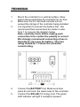
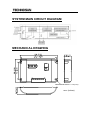
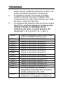
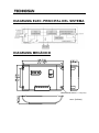
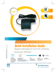
ELECSUN 10A12/24V-LC-T
SOLAR CHARGE CONTROLLER
WITH LIGHTING CONTROL
REGULADOR DE CARGA
CON CONTROL DE ILUMINACIÓN
______________________________________
USER MANUAL / MANUAL DE USUARIO
English version (EN)
RATINGS
12V or 12/24V auto work.
Elecsun 10A12/24V-LC-T 12V or 12/24V auto-work, 10A.
NOTES: For use with solar panels only, for use with
sealed battery in 12 or 24V systems.
TECHNICAL INFORMATION
Rated solar input
Rated load
25% Current overload
Load disconnect
Load reconnect
Equalization voltage (60 min.)
Boost voltage (60 min.)
Float voltage
Temp Comp.(mV/ºC)
Terminals
Temperature
12Volt
24Volt
10A
10A
10A
10A
1 min.
1 min.
11.1V
22.2V
12.6V
25.20V
14.8V
29.6V
14.4V
28.8V
13.7V
27.4V
-30mV
-60mV
Wire sizes to 2.5mm²
-35ºC to +55ºC
QUICK START INSTRUCTIONS
This section provides a brief overview of how to get
started using the controller. However, please review the
entire manual to ensure best performance and years of
trouble-free service.
1.
2.
3.
4.
5.
Mount the controller to a vertical surface. Allow
space above and below the controller for air flow.
Make sure the PV and load currents will not
exceed the ratings of the controller being installed.
It is important to connect the battery first. We
recommend that connections be made in order
from 1 to 6 as per the diagram below.
Note: carefully check before making each
connection to be certain the polarity is correct.
We strongly recommend connecting a fuse in
the battery+ line near the battery. The fuse
rating should be 1.5 times the controller
current rating.
Connect the BATTERY first. Make sure bare
wires do not touch the metal case of the controller.
Connect the SOLAR (PV array) next. The green
LED indicator will light if sunlight is present.
6.
Connect the LIGHT last. To verify system
operation, read the next section and put the
system in Mode 6. or 7. which will allow ON / OFF
control via the switch.
LIGHTING CONTROL OPTIONS
1.
2.
3.
The ON / OFF switch has two functions. To turn
the load on and off momentarily press the switch.
To use it for setting options, press for 5 seconds
to advance through the 16 work modes described
below.
The controller requires 10 minutes of continuous
transition values before it starts to work. These
constraints avoid false transitions due to lighting
or dark storm clouds.
The list below describes each of the modes,
please note that the last 8 modes will have the
point after the mode lit:
Number 0
Number 1
Number 2
Number 3
Number 4
Number 5
Number 6
Number 7
Number 0.
Number 1.
Number 2.
Number 3.
Dusk-to-Dawn, light is on all night.
Light is turned on after sundown for 1 h.
Light is turned on after sundown for 2 h.
Light is turned on after sundown for 3 h.
Light is turned on after sundown for 4 h.
Light is turned on after sundown for 5 h.
Light is turned on after sundown for 6 h.
Light is turned on after sundown for 7 h.
Light is turned on after sundown for 8 h.
Light is turned on after sundown for 9 h.
Light is turned on after sundown for 10 h.
Light is turned on after sundown for 11 h.
Number 4.
Number 5.
Number 6.
Number 7.
Light is turned on after sundown for 12 h.
Light is turned on after sundown for 13 h.
Light remains turned off, on/off mode.
Test mode, light on after it detects no
light, light off after it detects light.
LED INDICATOR
! Green ON when solar is charging
battery.
! Green blink when the system over
voltage.
! Green ON when battery level in the
right range.
! Green slowly flashing when battery
level full.
! Yellow ON when battery level low
! Red ON when loads cut off.
! Red ON when the output is on.
! Red slowly flashing when it is over
load.
! (the load amps is 1.25 times of
rated current for 60 seconds, or the
load amps is 1.5 times of rated
current for 5 seconds).
! Red fast flashing when the load is
short-circuit.
Please note:
The output will be cut off once there is
either short circuit or over load. While
short circuit occurs, disconnect the
loads and check the error loads, then
press the switch, the load will be
reconnected automatically after 3s.
There is one automatic load
reconnect attempts after 10s while
first time short circuit. For more one
time short circuit, users need press
switch to reconnect loads.
While the over load occurs,
disconnect some loads and press the
switch, the load will be reconnect
automatically after 3s.
TROUBLE SHOOTING
1.
PV indicator is off when it is daytime
a)
b)
c)
d)
e)
The green Charging LED should be on
during day time.
Check that the proper battery type has
been selected.
Check that all wire connections in the
system are correct and tight. Check the
polarity(+ and -) of the connections.
Disconnect the PV and measure the PV
open-circuit voltage and confirm it is within
normal limits. If the voltage is low or zero,
check the connections at the PV array
itself.
With PV connected, measure the PV
voltage and the battery voltage at the
controller terminals. If the voltage at the
terminals is the same (within a few tenths
of a Volt), the PV array is charging the
battery. If the PV voltage is close to the
open circuit voltage of the panels and the
battery voltage is low, the controller is not
charging the batteries and may be
damaged.
2.
Charging LED indicator is blinking
a)
b)
3.
First check the operating conditions to
confirm that the voltage is higher than
specifications. Consider the temperature
compensation of the controller’s PWM
setpoint. If the temperature lower than 0ºC
the controller will regulate higher than
17V(17V is over voltage point).
Check that all wire connections in the
system are correct and tight.
Problems with operation of load
a)
b)
c)
If Load LED is fast flashing, there is a short
circuit. Look for short circuit.
If Load LED is slow flashing, there is an
overload condition. Check wiring to load,
check connections. If you have multiple
devices connected to the load, you may
need to measure the current of each device
to find defective device. Reduce the load,
and press the switch button, the controller
will turn on load after 30 seconds.
If load is not operating, check that the load
is turned on. Check that no system fuses
are defective. Check connections to the
load, and other controller and battery
connections. Make sure voltage drops in
the system wires are not too high.
INSPECTION AND MAINTENANCE
The following inspections and maintenance tasks are
recommended at least once per year for best controller
performance.
1.
2.
3.
4.
5.
6.
7.
8.
Confirm that the current levels of the solar array
and load do not exceed the controller ratings.
Tighten all the terminals. Inspect for loose,
broken, or burnt wire connections. Be certain no
loose strands of wire are touching other terminals
Verify the lights are working. This can be tested by
putting controller in mode 18 or 19 and using the
button as an on/off switch.
Check that the controller is securely mounted in a
clean environment. Inspect for dirt, insects and
corrosion.
Check the air flow around the controller is not
blocked.
Protect from sun and rain. Confirm that water is
not collecting under the cover.
Check that the controller functions and LED
indicators are correct for the system conditions at
that time.
Make sure the PV array is clean and clear of
debris and snow. Confirm the array is oriented
correctly for the installation location.
SYSTEM MAIN CIRCUIT DIAGRAM
MECHANICAL DRAWING
4MOUNTING HOLES ¢4.0 (0.16)
mm (inches)
Notes
_____________________________________________
_____________________________________________
_____________________________________________
_____________________________________________
_____________________________________________
_____________________________________________
_____________________________________________
_____________________________________________
_____________________________________________
_____________________________________________
_____________________________________________
_____________________________________________
_____________________________________________
_____________________________________________
_____________________________________________
_____________________________________________
_____________________________________________
Versión en español (ES)
VALORES
12V or 12/24V automático.
Elecsun 10A12/24V-LC-T 12V o 12/24V automático,
10A.
NOTA: Para uso exclusivo con paneles solares, usar
con baterías selladas en sistemas de 12 o 24V.
INFORMACIÓN TÉCNICA
Entrada nominal
Carga nominal
25% corriente de sobrecarga
Desconexión de carga
Reconexión de carga
Voltaje de ecualización
(60 minutos)
Elevación de voltaje (Bulk)
(60 minutos)
Voltaje de flotación
Comp. de temp. (mV/ºC)
Terminales
Temperatura
12Volt
10A
10A
1 min.
11.1V
12.6V
14.8V
24Volt
10A
10A
1 min.
22.2V
25.20V
29.6V
14.4V
28.8V
13.7V
27.4V
-30mV
-60mV
Cable calibre 2.5mm²
-35ºC a +55ºC
INSTRUCCIONES DE INICIO RÁPIDO
Esta sección proporciona una breve visión general de
como comenzar a usar el regulador. No obstante, por
favor revise el manual completo para asegurar el mejor
funcionamiento posible del regulador y evitar problemas
en el futuro.
1.
2.
3.
Monte el controlador en una superficie vertical.
Deje espacio suficiente encima y debajo del
regulador para permitir consultar las indicaciones
impresas y permitir el flujo del aire.
Asegúrese de que las corrientes de los paneles
solares y de carga no excedan los valores
permitidos por este regulador.
Es importante conectar en primer lugar la batería.
Recomendamos hacer las conexiones en orden
desde el 1 hasta el 6 tal y como se indica en el
diagrama inferior.
Nota: compruebe antes cuidadosamente cada
conexión para confirmar que la polaridad es
correcta. Recomendamos firmemente conectar
un fusible en la línea positiva cercana a la
batería. La capacidad del fusible debería ser
mínimo 1,5 veces mayor que el valor de
corriente.
4.
5.
6.
Conecte la BATERÍA primero. Asegúrese de que
los cables pelados no toquen la caja metálica del
regulador.
Conecte a continuación la entrada SOLAR (línea
de paneles FV). El LED indicador verde se
encenderá si hay luz solar presente.
Conecte finalmente la LUZ. Para verificar el
funcionamiento del sistema, lea la siguiente
sección y ponga el sistema en modo 6. o 7. que
permitirá el control de encendido (ON) / apagado
(OFF) a través del interruptor.
OPCIONES DE CONTROL DE ILUMINACIÓN
1.
El interruptor ON / OFF switch tiene dos
funciones. Para cambiar entre estados ON/OFF la
carga presione y suelte un instante el interruptor.
Para usar el interruptor como configurador de las
opciones, presiónelo durante 5 segundos para
2.
3.
poder avanzar mediante pulsaciones entre los 16
modos de trabajo descritos a continuación.
El regulador requiere 10 minutos de trabajo
continuo antes de comenzar a trabajar. Esta
limitación permite evitar falsos positivos por culpa
de rayos o nubes tormentosas.
La siguiente lista describe cada uno de los modos
disponibles, por favor tenga en cuenta que los
últimos 8 modos se distinguen de los
anteriores por tener un punto después del
número (0, 1, 2, 3, 4, 5, 6, 7, 0., 1., etc...):
Modo 0
Modo 1
Modo 2
Modo 3
Modo 4
Modo 5
Modo 6
Modo 7
Modo 0.
Modo 1.
Modo 2.
Modo 3.
Modo 4.
Modo 5.
Modo 6.
Modo 7.
Desde el anochecer hasta el anochecer,
luces encendidas toda la noche.
Desde el anochecer durante 1 h.
Desde el anochecer durante 2 h.
Desde el anochecer durante 3 h.
Desde el anochecer durante 4 h.
Desde el anochecer durante 5 h.
Desde el anochecer durante 6 h.
Desde el anochecer durante 7 h.
Desde el anochecer durante 8 h.
Desde el anochecer durante 9 h.
Desde el anochecer durante 10 h.
Desde el anochecer durante 11 h.
Desde el anochecer durante 12 h.
Desde el anochecer durante 13 h.
La luz permanece encendida o
apagada permanentemente en base al
estado indicado de ON / OFF.
Modo de pruebas, luz encendida si no
detecta luz, luz apagada si detecta luz.
INDICADORES LED
! Verde encendido cuando la energía
solar está cargando la batería.
! Verde parpadeando cuando hay
sobrevoltaje.
! Verde encendido cuando el nivel de
la batería está en el rango correcto.
! Verde parpadeando lentamente.
cuando el nivel de la batería esté
lleno.
! Amarillo encendido cuando la
batería tiene nivel bajo.
! Rojo encendido cuando la carga se
interrumpe.
! Rojo encendido cuando la salida
está encendida.
! Rojo parpadeando lentamente
cuando hay sobrecarga.
(La carga en amperios es 1.25
veces el valor de corriente para 60
segundos, o la corriente de carga
es 1,5 veces el valor de corriente
para 5 segundos).
! Rojo parpadeando rápidamente
cuando la carga está en
cortocircuito.
Nota importante:
La salida será cortada si hay un
cortocircuito o sobrecarga. Mientras
ocurra el cortocircuito, desconecte las
cargas y compruebe los errores de
carga, a continuación presione el
interruptor, la carga se reanudará
después de 3 segundos. La primera
vez que ocurra un cortocircuito habrá
un intento de reconexión automática
de carga después de 10 segundos. Si
el cortocircuito ocurre más de una
vez, el usuario necesitará presionar el
interruptor manualmente para
reconectar la carga.
Cuando ocurra una sobrecarga,
desconecte algunas cargas y
presione el interruptor, la carga se
reanudará automáticamente después
de 3 segundos.
SOLUCIÓN DE PROBLEMAS
1.
El indicador de FV (paneles solares) está
apagado cuando es de día
a)
b)
c)
d)
e)
La luz del LED de carga debe estar verde
durante el día.
Compruebe que se ha seleccionado el tipo
de batería correcta.
Compruebe que todas las conexiones de
cables del sistema son correctos y están
ajustadas. Compruebe la polaridad positiva
y negativa de las conexiones.
Desconecte la carga FV y mida el voltaje
del sistema FV en circuito abierto y
confirme si entra en los límites normales. Si
el voltaje es bajo o cero, compruebe las
conexiones de la línea de paneles solares
Con la carga FV conectada, mida el voltaje
de la la carga FV y de la batería en los
terminales del regulador. Si el voltaje entre
los terminales es la misma (con una
diferencia de pocas décimas), la carga FV
está cargando la batería. Si el voltaje de la
carga FV es cercana al voltaje en circuito
abierto y el voltaje de la batería es bajo, el
regulador no está cargando las baterías y
puede dañarse.
2.
El indicador de carga LED está parpadeando
a)
b)
3.
Compruebe en primer lugar las
condiciones de funcionamiento para
confirmar que el voltaje es mayor
que las especificaciones. Considere
la temperatura de compensación del
regulador. Si la temperatura es
menor que 0ºC el regulador regulará
más de 17V (17V es el punto de
sobrevoltaje).
Compruebe que las conexiones de
los cables del sistema están
correctos y ajustados.
Problemas en la operación de carga
a)
b)
c)
Si el LED de carga parpadea
rápidamente es que hay un
cortocircuito, localícelo.
Si el LED de carga parpadea
lentamente, entonces hay una
sobrecarga. Compruebe el cable
que va a la carga y sus conexiones.
Si tiene varios aparatos conectados
a la carga, puede ser necesario
medir la corriente de cada aparato
para encontrar cual es el
defectuoso. Reducida la carga pulse
el interruptor, el regulador volverá a
cargar pasados 30 segundos.
Si la carga no está funcionando,
compruebe que la carga está
encendida. Compruebe que no hay
fusibles defectuosos. Compruebe
las conexiones a la carga, y otras
conexiones al regulador y la batería.
Asegúrese que la caída de voltaje
en el cableado del sistema no es
demasiado elevado.
INSPECCIÓN Y MANTENIMIENTO
Las siguientes tareas de inspección y mantenimiento son
recomendadas como mínimo una vez al año para un
mejor rendimiento del regulador.
1.
2.
3.
4.
5.
6.
Asegúrese que los nivel de corriente y carga en la
línea de paneles solares no excede los valores
permitidos por el regulador.
Apriete bien las conexiones. Inspeccione en
búsqueda de cables pelados, rotos o quemados.
Asegúrese que no hay hebras de cable tocando
otros terminales.
Verifique que las luces funcionan correctamente.
Esto puede comprobarse poniendo el regulador
en modo 18 o 19 y usando el interruptor como
encendido / apagado.
Compruebe que el regulador está firmemente
montado de forma segura en un ambiente limpio.
Inspeccione frente a suciedad, insectos o
corrosión.
Compruebe que el flujo del aire alrededor del
regulador no esté bloqueado.
Proteja el regulador del sol y la lluvia. Asegúrese
que no se acumula agua en la carcasa.
7.
8.
Compruebe que las funciones e indicadores LED
del regulador funcionan correctamente para las
funciones del sistema en ese momento.
Asegúrese de que el sistema fotovoltaico está
limpio y libre de escombros o nieve. Confirme que
la línea de paneles solares esté orientada
correctamente para el lugar de instalación del
sistema.
DIAGRAMA ELEC. PRINCIPAL DEL SISTEMA
DIAGRAMA MECÁNICO
4MOUNTING HOLES ¢4.0 (0.16)
mm (inches)
Notas
_____________________________________________
_____________________________________________
_____________________________________________
_____________________________________________
_____________________________________________
_____________________________________________
_____________________________________________
_____________________________________________
_____________________________________________
_____________________________________________
_____________________________________________
_____________________________________________
_____________________________________________
_____________________________________________
_____________________________________________
_____________________________________________
_____________________________________________