1
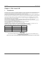
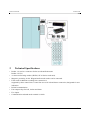
Access Lift
User Manual
Synel Industries Ltd.
Manual 4/16/07, Catalog no. 653722Part no. (ACCLFT-222-01)
All rights reserved. Reproduction or use, without express permission of
editorial or pictorial content, in any manner is prohibited. No patent
liability is assumed with respect to the use of the information contained
herein. While every precaution has been taken in the preparation of this
manual, Synel Industries Ltd. assumes no responsibility for errors or
omissions. Neither is any liability assumed for damages resulting from
the use of the information contained herein.
SY is a trademark of Synel Industries Ltd.
All trade names referenced herein are either trademarks or registered
trademarks of their respective companies.
Terminology used in this manual
Warning
To warn readers about possible damage to equipment or data or about
potential problems in the outcome of what they are doing.
Note: To warn readers about the possibility of minor injury to themselves or others.
Caution
To emphasize points or remind readers of something, or to indicate
minor problems in the outcome of what they are doing.
Synel Industries Ltd.
SY-780/A User Manual
Synel Industries Ltd.
3
Access Lift
Table of Contents
Chapter 1 -The Access Lift ...................................................................................................... 6
1Introduction ......................................................................................................................... 6
2Technical Specifications ...................................................................................................... 7
2.1Physical Dimensions.................................................................................................... 8
2.2Power Requirements .................................................................................................... 8
2.3Optional Accessories ................................................................................................... 8
3Physical Description ............................................................................................................ 8
3.1Front Connector Panel ................................................................................................. 9
3.2 Back Block terminal Panel ......................................................................................... 9
4Installation ........................................................................................................................... 9
4.1Unpacking.................................................................................................................... 9
4.2Package Contents ......................................................................................................... 9
4.3Hardware Setting ....................................................................................................... 10
4.4Mounting.................................................................................................................... 10
5Communication ..................................................................................................................11
5.1Host computer Interfacing ..........................................................................................11
5.2Communication cables Characteristics .......................................................................11
6Setting Connectors & Jumpers ...........................................................................................11
6.1Dip-Switch (S1) ..........................................................................................................11
6.2Terminal ID.................................................................................................................11
6.3Reader 1/2 - Jumpers position ................................................................................... 12
1.3.1Other- Jumpers position.......................................................................................... 12
1.4Connection to I/O model............................................................................................ 13
1.4.0.1P2 - Address Selection. ................................................................................... 14
Appendix A -Internal Connectors ........................................................................................ 16
Appendix B -Access Lift External Connectors .................................................................... 18
4
Access Lift
5
Access Lift
The Access Lift
Chapter 1 -The Access Lift
1
Introduction
The Access Lift is a local access controller installed on elevators to manage access to specific floors acting
as a buffer to the elevator floor selection mechanism. A person using the elevator identifies himself to
Access Lift which determines the floors the person is allowed to access.
The buttons for the floors the person is allowed access to are activated and can be selected. The buttons for
the floors the person is not allowed access to remain un-activated and the floor buttons can not be pressed.
Access Lift is unique in that it provides a solution for monitoring access to buildings of up to 28 floor
levels. On it’s own Access Lift can monitor access to 4 floors. Together with Synel I/O systems Access
Lift can monitor access to up to 28 floors.
The Access Lift is managed by a standard master unit, which oversees the access restrictions.
Access Lift and it’s complying systems are installed into the elevator wall. Access Lift acts as a buffer to
the elevator floor selection button mechanism.
Access Lift capabilities are extended using Synel I/O cards (of 8 outputs).
Using Synel I/O you can set up to 12 ID’s for access control.
The number of ID’s available for floors depends on the number of ID’s which are already in use. For
example, if you need to set 28 floors you can start setting the ID’s from ID 4.
The I/O model enables setting access control to additional floor levels as follows:
Number of floors
Number of I/O cards
number of ID’s
4
12
20
28
no additional card
1
2
3
4
12
20
28
Warning!
The connection between Access Lift and the elevator mechanism is to be installed only by a
Certified Elevator Technician.
Synel is in no way or form responsible for any malfunctions which may occur in the elevator.
6
The Access Lift
2
Access Lift
Technical Specifications
• Reader 1 is used as a connector for the user identification unit.
Reader 2 is N/A.
• A connector for badge readers (PRX30, SY-10 Series reader unit).
• Magnetic, proximity, 26 bit Wiegand and barcode readers can be connected.
• Each reader in addition to reading lines connection is
supported by three control lines. Control line serves for led and buzzer connection, designated for user
indication.
• RS-485 communication
• Four output relays for bell, 2xdoor and alarm.
• Five inputs
• Communication at dumb mode terminal is 19200.
7
Access Lift
2.1
The Access Lift
Physical Dimensions
Height - 18.0 cm (7 inch)
Width – 11.2cm.(41/2 inch)
Depth – 3.4 cm.(1 5/16 inch)
Operating temperature: -5 to +45oC
Relative humidity: 90%, non-condensing
2.2
Power Requirements
It is recommended to connect Access Lift to a power supply outlet via Power socket on the front panel, in
addition to power supplied via the master unit. The following lists the power supply specifications:
• 12 Vdc
• power consumption: 1 watt
• recommended power supply adaptor: 9 to 14 Vdc, max @ 880 mA. Adaptors can be connected using
wiring to the terminal block position Power.
2.3
Optional Accessories
Product
Description
Quantity
Catalog No.
Readers
Designed for only one reader
PRX-30
Proximity reader
1
60270004
SY-1
Magnetic reader
1
360055
SY-10/B
Bar code reader, connection up
to 300m
1
01000102
SY-10/M
Magnetic reader, connection
up to 300m
1
01000101
Reader unit
Reader bar code unit
1
60250000
Reader unit
Reader magnetic unit
1
60250200
I/O
I/O Extension
Note: Each I/O Extension
added to Access Lift uses a
power supply adaptor of it’s
own.
3
3
Physical Description
The Access Lift terminal is housed in a strong metal enclosure.
Access Lift and it’s acompanying components are installed into the elevator mechanism panel.
The connector panel is located at the front and back panel of the casing. Located therein, are socket
openings for all external connections.
8
The Access Lift
3.1
1.
2.
3.
4.
5.
3.2
Access Lift
Front Connector Panel
Led indicator
Power supply
External Reader 1
I2C – I/O Extension
Host – RS-485
Back Block terminal Panel
A Block terminal for input/output connection purposes.
1.
Press the block terminal with a 3mm flat screwdriver and turn Clock wise until the spring is pressed.
Caution:
Do not press screwdriver upward against the enclosure.
2.
3.
4
4.1
Perform wiring, turn to release spring.
Remove screwdriver.
Installation
Unpacking
• Do not throw away the box or packing materials.
• Check the box and contents for signs of damage that may have occurred during shipment. After
checking the box, carefully unpack and check for the following items:
4.2
Package Contents
The Access Lift package contains:
1.
Access Lift terminal
2.
Connection/splitter box
3.
RJ-45 30cm cable
4.
Two RS-45 10 pin male
5.
Four flat head Philips screws and anchors, for terminal mounting purposes
6.
Mounting template
7.
Product manual
9
Access Lift
4.3
The Access Lift
Hardware Setting
For manual hardware setting refer to “Setting Connectors & Jumpers” on page 11, and “Terminal ID” on
page 11.
You can also refer to the section describing Jumper and Connector technical data.
4.4
Mounting
Access Lift contains computer components and uses communication cables interfacing therefore, it should
not be mounted where it will be exposed to extreme heat or cold, water, steam, violent radiation, high
electromagnetic radiation including high voltage power lines and electrical device. If the communication
cable is to be wired through the wall, make sure that it is safe to drill a hole at the desired location.
Two mounting options are available for this unit:
Option A- Horizontal position
Step 1.
Step 2.
Step 3.
Step 4.
Step 5.
Mark the horizontal screws position, use the mounting template.
Drill holes using a 3/16" (4.7mm)-drill bit.
Place anchors and fasten screws to the wall.
Hang Access IV back panel, allow a 3mm gap between unit and wall.
Route block terminal wiring and connect them to the unit. Prevent wiring disconnection, secure
wiring to the back panel using a clamp fasten by two screws.
Option B - Vertical position
Step 1.
Step 2.
Step 3.
Step 4.
Step 5.
Disassemble Access IV back panel, remove two fastening screws at the unit side panels.
Remove back panel.
Fasten back panel on the wall, place two screws at
position B.
Place front cover and secure using two short screws at the unit side panels.
Route block terminal wiring and connect them to the unit. Prevent wiring disconnection, secure
wiring to the back panel using a clamp fasten by two screws.
Option A
Option B
10
The Access Lift
5
Access Lift
Communication
5.1
Host computer Interfacing
Communication with the host computer is performed via the Master unit. The communication between the
master unit and terminals is performed at 19200 bps. Access Lift sends a terminal response to the master
unit, the actual terminal ID is set according to dipswitch therefore the virtual terminal is as defined in the
terminal: ID+4/12/20/28 (according to dipswitch 6 and 7 settings on the I/O card connected to Access
Lift).
Note: The Master unit 6 pin connector is connected to Access Lift 8 pin Host connector on the front
panel.
5.2
Communication cables Characteristics
Follow the listed guidelines to install the communications cables:
Do not install the cable near EMI sources, such as:
• Motors, generators, alternators, and transformers
• Air conditioners, elevators
• Radio/television transmitters, signal generators and internal communication networks
• Cables should not be within 30 cm. (1 foot) of power lines of less than 5 KVA.
• Cables should not be within 60 cm. (2 feet) of power lines in the 5-10 KVA range.
Cables should not be within 1.5 meters (5 feet) of power lines of more than 10 KVA. The cables should not
run parallel to power lines for more than 15 meters (49 feet).
It is best to use a single cable for the communication line. If it is not possible to use a continuous cable only
one indoors connection is allowed, constructed in one of these options:
• Using two connectors with appropriate shielding and cover.
• Using a connection box.
• For aerial installation, use N.Y.Y. shielded cables.
6
Setting Connectors & Jumpers
6.1
Dip-Switch (S1)
1-5 - Defines the basic ID of the Access Lift
6-7 - Sets the number of I/O cards attached to Access Lift as describes in the table below
Switch 6
Switch 7
Number of I/O cards
Number of floors
OFF
ON
OFF
ON
OFF
OFF
ON
ON
no additional card
1
2
3
4
12
20
28
6.2
Terminal ID
To set an ID for each floor:
1.
Start counting from a base number which is the next available ID on the Master unit you are using.
For example, if the Master unit is already managing access to 4 doorways using 4 ID’s, start your
count from ID 5.
11
Access Lift
2.
The Access Lift
Add the number appearing in the ID No. column in the table below to the floor number set on
switches 6 and 7, as described in the Dip-Switch (S1) section.
You can set up to 28 + 3 ID’s.
ID No.* Jumper Settings
4
3
2
01
OFF OFF OFF
02
OFF OFF OFF
03
OFF OFF ON
04
OFF OFF ON
05
OFF ON
OFF
06
OFF ON
OFF
07
OFF ON
ON
08
OFF ON
ON
09
ON
OFF OFF
10
ON
OFF OFF
11
ON
OFF ON
12
ON
OFF ON
13
ON
ON
OFF
14
ON
ON
OFF
15
ON
ON
ON
16
ON
ON
ON
6.3
1
OFF
ON
OFF
ON
OFF
ON
OFF
ON
OFF
ON
OFF
ON
OFF
ON
OFF
ON
S1 - Switches set up
1-4Terminal identification:
Jumper 1 is LSB; jumper 4 is MSB.
Identification number is in binary format,
that is a closed jumper is considered as a
logical 1 and in open jumper, as a logical
0.
Reader 1/2 - Jumpers position
No
1
Jumper
JP1
Description
Reader 2 type
2
JP2
Reader 1 type
3
J3
Reader 2 type
4
J4
Reader 1 type
1.3.1
Value
Magnetic - 1-2
Bar code - 2-3
Magnetic - 1-2
Bar code - 2-3
Magnetic - Open
Wiegand - Close
Magnetic - Open
Wiegand - Close
Default
N/A
1-2
N/A
Open
Other- Jumpers position
No
1
Jumper
J5
Description
Value
Vcc current measuring Vcc
Default
Close
2
JP3
12Vin: 1-2
Open
3
JP4
12V from Master
Control Unit
ON, OFF
Tamper switch
ON: 1-2
OFF: 2-3
1-2
12
The Access Lift
4
JP5
5
JP6
6
JP10
7
JP11
8
JP12
9
JP13
10
JP14
11
JP15
1.4
Access Lift
Pin 2, communication I2C data: 1-2
connector
External led 1: 2-3
Pin 7, communication I2C Clock: 1-2
connector
External led 2: 2-3
Open
Open
Input1 AC/DC OR
Normal operation
(Dry contact)
2-3 Closed - AC/DC Normal
operation
1-2
3-4
Input 4 - operated with 2-3 Closed- AC/DC Normal
AC/DC OR
operation
1-2
Normal operation
3-4
(Dry contact)
Relay 1
Closed - DC
Closed
Open - AC
Relay 2
Closed - DC
Closed
Open - AC
Enables/disables test 1-2 - Enable
Disable
mode
2-3 - Disable
For measuring the
-------Closed
device power
consumption
Connection to I/O model
The I/O model acts as an extension to Access Lift which enables setting access control to additional floor
levels.
I/O cards are added to extend Access Lift capabilities as follows:
Number of floors
Number of I/O cards
4
12
20
28
no additional card
1
2
3
13
Access Lift
The Access Lift
The typical setup for I/O models is as follows.
Note: Each I/O Extension added to Access Lift uses a power supply adaptor of it’s own.
1.4.0.1
A
OPEN
OPEN
OPEN
14
P2 - Address Selection.
B
OPEN
OPEN
CLOSE
C
OPEN
CLOSE
OPEN
I/O Address
ID =0
ID=1
ID=2
The Access Lift
Access Lift
15
Access Lift
Appendix A -Internal Connectors
Communication Board (J1 - Molex 8 Pin)
Pin
1
2
3
4
5
6
7
8
Signal
VCC
VCC
TXD
RX1
485
RX2
GND
GND
Value
5V
5V
Data
Data
Logic
Data
0V
0V
Remarks
Voltage
Voltage
Transmit
Receive 1
Dirction
Receive 2
Ground
Ground
Communication return (J2 -Molex 6 Pin)
Pin
1
2
3
4
5
6
Signal
NC
-TRXD
+TRXD
RXD
TXD
NC
Value
level RS-485
level RS-485
level RS-232
level RS-232
Remarks
N/A
RS-485
RS-485
RS-232
RS-232
N/A
P7 - Molex - 3 pin
Pin
1
2
Signal
VCC
EXT.RES
Value
5V
5V
3
GND
0V
16
Description
Remarks
Power supply
Voltage
External reset
Reset
input - Active low
Ground
Ground
Access Lift
17
Access Lift
Appendix B -Access Lift External Connectors
HOST RJ-45 (8 pin with LEDs)
• Communications with master, Access IV 2-7 installation pins are compatible with Access II 1-6 pins
• RS-485 Communication with host.
Pin
1
2
3
4
5
6
7
8
RXD
I2C/Led
Vin or Vout
+TXD, RXD
+TXD, RXD
GND
I 2C
TXD
Master
I2C
12 Vin
+TXD,RXD
+TXD, RXD
GND
I2 C
-
Host
RXD
GND
TXD
Remarks
RS-232
According to JP5
According to JP3
RS-485
RS-485
Depend on JP6
RS-232
I2C BusRJ 11 (6 Pin)
Pin
1
Signal
Serial Clock
Value
SCL
2
3
4
5
6
NC
NC
NC
GND
Serial data
SDA
18
Remarks
Clock I2C
N/A
N/A
N/A
Ground
Data I2C
Access Lift
Reader 1 RJ 45 (10 pin)
Pin
Magnetic
Device
Paxton
Bar-Code Wiegand
PRX-30
Remarks
For RS-485
signal only
Max current
35 mA
Max current
25mA
Signal
1
RDD1 -
Data -
-
2
BZ1
Led 1
Buzzer
3
LD1
Led 2
Led 1
4
5
6
VCC
GND
LD2
VCC
GND
Led 3
VCC
GND
7
RDC1+
Clock
Clock
-
Data 0
Clock
8
RDD1+
Data
Data
Data
Data 1
Data
9
10
12 V
RDC1-
Clock -
-
-
-
VCC
GND
VCC
GND
VCC
GND
Led 2
Max current
25 mA
Clock + , For
RS-485
Data + , For
RS – 485
For RS 485
signal only
Power Socket-PL1
Pin
1
2
Signal
VCC
GND
Value
+12 V
0V
Remarks
Voltage for power supply
Ground
Relays (J7 - Block terminal 23 Pin)
Pin
1
Port
Relay 2
Signal Value Function
A112
Floor 2
Function
Normally
closed
2
Relay 2
B2
3
4
Relay 2
Relay 3
C2
A113
Normally
Open
Common
Normally
closed
5
Relay 3
B3
6
7
Relay 3
Relay 4
C3
A114
Floor 3
Floor 4
Normally
open
Common
Normally
closed
Remarks
Max current
24 Vdc @ 1A
110 Vac @0.5 A
Max current
24 Vdc @ 1A
110 Vac @0.5 A
Max current
24 Vdc @ 1A
110 Vac @0.5 A
19
Access Lift
8
Relay 4
B4
9
10
Relay 4
Relay 1
C4
A111
11
Relay 1
B1
12
13
14
15
16
17
18
19
20
21
22
23
Relay 1
Input 1
Input 1
Input 2
Input 2
Input 3
Input 3
Input 4
Input 4
Input 5
Input 5
Input 5
C1
20
Floor 1
Normally
open
Common
Normally
closed
Max current
24 Vdc @ 1A
110 Vac @0.5 A
Normally
open
Common
GND N/A
IP1
Data signal
Max current 10mA
Data signal
Max current 10mA
Data signal
Max current 10mA
Data signal
Max current 10mA
Data signal
Max current 10mA
GND N/A
IP2
GND N/A
IP3
GND N/A
IP4
GND N/A
IP5
GND
Access Lift
21
Access Lift
Synel Industries Ltd.
2 Hamada St. POB 142, Yokneam Industrial Park, Israel, 20692
Tel: +972-4-959 6777Fax: +972-4-959 0729
Site: www.synel.com
Tel-Aviv BranchTel: +972 9 775 0400
UK BranchTel: +44-181-900 9991
NA BranchTel: +1-905-678 2605
22
Access Lift
23