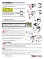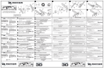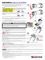
1
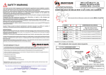
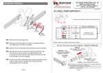
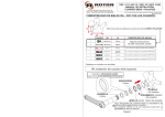
Revisión: 2 de Junio de 2008
Gracias por la confianza depositada en ROTOR al adquirir este producto.
Antes de proceder a la instalación, lea atentamente este manual y practique la instalación de
la careta de manillar en vacío para familiarizarse con la TECNOLOGÍA DTT.
1
ABRIR
_______INSTALACIÓN EN EL TUBO DE DIRECCIÓN____________________________
ATENCIÓN:
El roscado y montaje de los tornillos del collar de
dirección no es convencional, pero su apriete es
estandar: Los sentidos de apertura y cierre
vienen indicados en la propia potencia:
r
=
c er r a
rir
ab
j
Los tornillos vienen de fábrica centrados. ABRA el collar de dirección girando los tornillos
con una llave Torx T25 sin forzar (1-2 vueltas aproximadamente).
RECUERDE:
c er r
ab
rir
5 N·m
a
r
=
2
Coloque la potencia deslizándola en el tubo de dirección de la horquilla.
k
6 mm
Una vez instalada la correspondiente tapa de dirección, APRIETE ambos tornillos del
collar de dirección hasta un par de apriete aproximado de 5 N·m
CERRAR
3
_______INSTALACIÓN DEL MANILLAR_____________________________________
l Desmonte la careta, aflojando los tornillos alternativamente cada 1 vuelta. Una vez
quede liberada, con la careta en la mano, posicione TODOS los tornillos por IGUAL,
sobresaliendo aproximadamente 6mm de la cara plana interior de la careta (Ver figura 3).
6 mm
¡ATENCIÓN!: Usar pasta de fricción ROTOR es recomendable para cualquier montaje
pues evita deslizamientos indeseados aún con pares de apriete inferiores, pero en
particular su uso es necesario con manillares de carretera para evitar que se apriete el
manillar por encima de las recomendaciones de su fabricante.
Aplicar la pasta de fricción en la careta y el cuerpo de la potencia.
m
4
Coloque el manillar en la potencia y a continuación la careta frontal. Use una llave Torx
T25, asegurándose de que entra hasta el fondo en el tornillo y apretando contra la potencia
empiece enroscando media vuelta cada tornillo, repitiendo esta secuencialmente hasta
completar 1 vuelta por tornillo.
n
COMPRUEBE QUE CADA TORNILLO HA COGIDO ROSCA EN LA PRIMERA
VUELTA.
IMPORTANTE: Si al inicio uno de los tornillos hubiese perdido una vuelta, al
final quedará más adentro. Asegúrese de que los tornillos cogen rosca
inicialmente a la vez.
5
Continúe enroscando alternativamente los 4 tornillos cada 1 vuelta, de manera que
las caras planas de la careta y de la potencia se mantengan en todo momento paralelas,
hasta que el manillar quede sujeto firmemente. Los tornillos deben quedar entonces
aproximadamente enrasados con la careta, y esta a su vez, separada de la potencia por
igual en los 4 extremos.
Ir apretando poco a
poco llevando
siempre las ranuras
paralelas
Si los tornillos se adentran en la careta, repita el montaje desde el paso-3 posicionando los
tornillos a 5.5mm de la cara plana de la careta y asegúrese de no enroscarlos en vacío la
primera vuelta en el paso-4.
Si los tornillos quedan por fuera, ir al paso-3 y posicionar los tornillos a 6.5mm
o Asegúrese que la llave Torx T25 entra hasta el fondo y apriete firmemente los tornillos
(aproximadamente a 6-8 N·m)
NO FORZAR LOS TORNILLOS:
SI VAN DUROS ANTES DEL
APRIETE FINAL ES PORQUE LA
CARETA ESTÁ CRUZADA
6
Apretar firmemente (6-8 N·m)
AVISOS DE SEGURIDAD
Este manual contiene información muy útil e importante acerca de la correcta instalación, uso y mantenimiento de su potencia de manillar ROTOR SX. Debe leer, comprender y seguir cuidadosamente las
instrucciones que aparecen en este manual. Mantenga el manual en un lugar seguro para futuras consultas.
No realice ninguna modificación o ajuste que no esté explícitamente descrita en este manual. Si tuviera alguna duda sobre su capacidad para llevar a cabo la instalación o mantenimiento, por favor, acuda a un
taller cualificado.
Una instalación u operación de mantenimiento incorrecta podría provocar un accidente con resultado de lesiones o incluso la muerte.
Por favor, lleve su bicicleta regularmente a un taller cualificado para inspeccionar cualquier signo de fatiga, rotura, deformación o impacto. En caso que aparezca alguno de ellos, la potencia ha de ser
reemplazada inmediatamente.
Si tiene cualquier duda, comuníquela en su punto de venta ROTOR más cercano, o contacte con [email protected].
MANTENIMIENTO
Inspeccione su potencia ROTOR SX en busca de impactos, fisuras, perdida de piezas o deformaciones antes de cada uso, así como después de cada caída. Si hay presencia de algunas de las circunstancias
previamente mencionadas, la potencia ha de ser reemplazada inmediatamente. ATENCIÓN: El uso continuado de piezas dañadas anula la grantía y puede ocasionar perdida de control de la bicicleta, así
como daños severos e incluso la muerte.
Es responsabilidad del usuario examinar el producto regularmente para determinar su revisión o sustitución. El ciclista debe inspeccionar la bicicleta, así como sus componentes, con frecuencia para localizar
daños producidos por el uso normal o abusivo. Revise, por favor, estos daños después de cada salida.
CONDICIONES DE LA GARANTIA
- La potencia de manillar ROTOR SX está garantizada durante 2 Años contra cualquier fallo de fabricación o material defectuoso. En el caso de existir alguna avería durante el periodo de garantía, Rotor
Componentes Tecnológicos se compromete a reparar o sustituir el componente o producto defectuoso sin cargo para el cliente. Además, en algunos países, Rotor está obligado a asegurar cualquier garantía
legal, definida por la ley de cada país, para la protección del usuario.
- Los componentes con una vida útil limitada por el uso y las roturas no achacables a defectos de fabricación no están cubiertas por esta garantía.
- Fallos o roturas causadas por un uso inapropiado, instalación defectuosa o un mantenimiento inadecuado (según se indica en el manual de usuario) no están cubiertos por esta garantía.
- Conserve su factura de compra, pues la necesitará para requerir la ejecución de esta garantía.
- La garantía será anulada en los siguientes casos:
- Incumplimiento de los requisitos anteriormente mencionados.
- Instalación inadecuada.
- Uso negligente o instalación de piezas inadecuadas.
Revised: June 2008
Thanks for choosing a ROTOR product.
Before starting the installation, please read this user manual carefully and try the faceplate
installation without the handlebar to learn about how the DTT TECHNOLOGY works.
1
OPEN
_____STEERER TUBE INSTALLATION____________________________
ATTENTION:
The steerer clamp bolts’ thread direction is
not conventional, but their tightening method
is STANDARD: The open and close
directions are laser etched on the stem:
2
j The bolts come from factory centered in the steerer clamp. OPEN the steerer clamp
5 N·m
(3.7 ft·lb)
turning the bolts with a Torx T25 wrench about 1-2 turns. REMEMBER:
Slide the stem over the steerer tube of the fork.
k Once the cap & necessary spacers of the ahead-set is installed,
THIGHTEN the
steerer clamp bolts up to 5 N·m (3.7 ft·lb)
6 mm
CLOSE
____HANDLEBAR INSTALLATION_______________________________
3
l Remove the faceplate, loosening the bolts alternatively (one revolution at a time) until
they release the stem´s body. With the faceplate in your hand be sure that all 4 bolts
protrude equally from the flat inner face of the stem´s faceplate about 6mm (Picture 3).
6 mm
¡ATTENTION!: Using ROTOR assembly paste is always recommended to avoid
slipping, but its use is mandatory with road handlebars to avoid clamping them at forces
above manufacturer´s indications.
Apply ROTOR assembly paste to the stem and faceplate surfaces.
m Put the handlebar on the stem and then place the faceplate against the stem´s body.
4
Using a Torx T25 key, making sure that the key reaches the bottom of the torx star, push the
faceplate against the stem body and start threading each bolt, a half revolution at a time.
Repeat the sequence until 1 complete revolution is completed for each bolt.
BE SURE THAT EACH BOLT THREADS INTO THE STEM BODY THE FIRST
REVOLUTION.
IMPORTANT: if one of the bolts threads into the stem after the other ones, it will
be misaligned. Be sure that bolts thread in the stem body at the same time.
n Continue threading the 4 bolts one revolution at a time, alternatively (so that the inner
faces of the face plate and stem´s body are parallel during the installation) until the
handlebar is clamped securely. The bolts should be then approximately flush with the
recess in the face plate, and the faceplate should be at the same distance from the stem at
all 4 corners.
5
Tighten each bolt
alternatively,
checking that the
faceplate clamps
evenly.
DO NOT OVERTHIGHTEN
THE BOLTS:
IF TIGHTENING
RESISTANCE INCREASES
SIGNIFICANTLY BEFORE
THE BAR IS CLAMPED
PROPERLY, THE FACEPLATE
IS MIS-ALIGNED AND MUST
BE CORRECTED.
If the bolts' heads sink into the face plate, go back to step-3 and turn the bolts so they
protude 5,5mm, and make sure that the bolts thread properly in step-4. If the bolts then
protude from the face plate, go back to step-3 and replace the bolts to 6.5mm.
o Be sure that the torx key reaches the bottom of the torx T25 star of the bolt and
6
thigten firmly the bolts up to 6-8 N·m (4.5 6 ft·lb).
Tighten firmly
(6-8 N·m)
SAFETY WARNING
TM
This owner's manual contains important and useful information regarding the proper installation, operation, care, and maintenance of your ROTOR product. Carefully read, follow and understand the
instructions given in this manual. You should keep this manual in a safe place for future reference.
Do not perform any modifications or adjustments that are not outlined in this manual. If you have any doubt whatsoever regarding your ability to service or repair this product, please take your bicycle to a
qualified repair shop for the assistance of a professional mechanic.
Incorrect installation or service may impair performance, and could result in a dangerous situation leading to injury or death.
Please have this product regularly inspected by a qualified mechanic for any signs of wear. Components that have experienced excessive wear, cracks, deformations or impacts need immediate replacement.
Failure to perform maintenance could drastically reduce the service life of your ROTOR SX stem and reduce its performance.
TM
If you have any questions, please contact a professional bike mechanic or your nearest ROTOR dealer for additional information, or contact [email protected].
Caution!: If any instructions within this User Manual are contrary to the instructions given by the manufacturer of your handlebar, fork, frame etc, contact their service department to explain your plan and
request their approval.
MAINTENANCE
Inspect your ROTOR SX stem for cracks and serious scratches, looseness, damage or weakness before each ride, and after every fall or crash. If any of the preceding conditions are present, do not use your
ROTOR SX stem until it has been repaired or replaced.
WARNING: Continuing to use damaged parts may lead to loss of control of the bicycle and cause injury or death.
It is the product users' responsibility to examine the product on a regular basis to determine the need for service or replacement. Cyclist should inspect their bicycle and parts on a regular basis in order to detect
damage that may have occurred from normal use and abuse. Check all parts for damage and wear before every use.
ROTOR WARRANTY POLICY:
The ROTOR SX STEM and its components are guaranteed for 2 YEARS against any manufacturer defects or defective materials. In the event of a warranty defect, ROTOR´s sole obligation under this
warranty is to repair or replace, at its option, the defective part or product at no charge. Moreover, in some countries, Rotor is obliged to ensure any legal warranty defined by law for the customer's
protection.
- Elements subject to wear and breakdowns that the manufacturer is not responsible for, are not covered by this warranty.
- Failures or breakdowns caused by improper use, poor assembly or inadequate maintenance as declared in the instructions or the user manual are not covered by this warranty.
- Always keep your receipt or invoice, this warranty does not cover products whose serial number or identification has been erased, damaged or modified.
- The following acts void this warranty:
- Failure to fulfil the requirements above.
- Improper installation.
- Improper use or installation of inadequate parts.