1
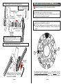
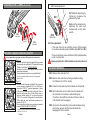
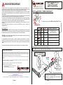
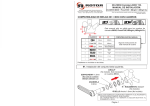
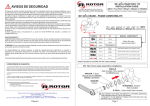
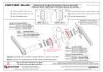
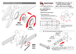
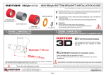
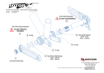
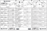
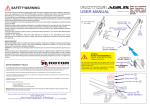
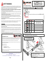
REX1.2
BCD 110 - 60.
MANUAL DE INSTALACIÓN.
SAFETY WARNING
CUADROS BB30 + PressFit30
ROTOR COMPONENTES TECNOLÓGICOS SL
This owners manual contains important and useful information regarding the proper installation, operation,
care, and maintenance of your ROTOR product. Carefully read, follow and understand the instructions as
detailed in this owner’s manual. Keep this manual in a safe place for future reference.
If you have any doubt whatsoever regarding your ability to install or service this product, please consult your
ROTOR dealer and seek the assistance of a professional bicycle mechanic. Do not perform any
modifications or adjustments that are not outlined in this manual.
Incorrect installation or servicing may impair performance, and could result in a dangerous situation leading
to serious injury or death.
Components that have experienced excessive wear, deformations or impacts or other damage need
immediate professional inspection or replacement.
Please have this product regularly inspected by a qualified mechanic for any signs of wear or damage.
Failure to perform necessary and essential maintenance could drastically reduce the service life of your
ROTOR product and reduce its performance.
If you have any questions, please contact a professional bike mechanic or your nearest ROTOR dealer for
additional information.
Pol.Ind. Conmar. C/Miño, 14. 28864, Ajalvir, Madrid, Spain.
Nota: las epecificaciones pueden cambiar por mejoras sin previo aviso.
Revisado: 09/2013
Phone: +34 91 884 38 46 / Fax: +34 91 884 38 65
COMPATIBILIDAD DE BIELAS REX1.2
D
CON LOS CUADROS:
Este manual sólo es válido para cuadros de montaña BB30 y PressFit30.
W
CUADRO
W
D
COMPATIBILIDAD DEL MANUAL
Caution!: Please consult the relevant manufacturer’s instruction manuals for your BB set or pedals, If
necessary, consult their technical service department for the correct installation procedure.
1
68/73mm
42mm
MAINTENANCE
2
68/73mm
46mm
Siga las instrucciones
de este manual de usuario
84mm
46mm
(Ver el manual de instalación ROTOR XC2 para BBright)
68/73mm
Rosca
BSA
(Ver el manual de instalación de cazoletas ROTOR BSA30)
Inspect your ROTOR product for wear, looseness or damage including cracks, dents and serious scratches,
before each ride and after every fall or crash. Do not use your ROTOR product until it has been thoroughly
inspected, repaired or replaced.
WARNING: Continuing to use damaged parts may lead to loss of control and cause serious injury or death.
Cyclists should inspect their whole bicycle and parts on a regular basis or consult with a professional bicycle
mechanic, to determine the need for service, or replacement and to detect damage that may have occurred
from normal use.
Check all parts for damage and wear before every use. Check the bolts and other fasteners periodically for
tightness. Ensure they are tightened to the correct torque values.
3
MTB
4
5
6
89
92
89,5mm
41mm
(Ver el manual de instalación de cazoletas ROTOR PF4130)
92mm
41mm
(Ver el manual de instalación de cazoletas ROTOR PF4130)
Pedalieres no incluidos con las bielas.
#1. Instalación del conjunto biela izquierda.
ROTOR WARRANTY POLICY:
- The ROTOR products and its components are guaranteed for 2 YEARS against any manufacturer defects or defective materials. In the
event of a warranty defect, Rotor´s sole obligation under this warranty is to repair or replace, at its option, the defective part or product at no
charge. Moreover, in some countries, Rotor is obliged to ensure any legal warranty defined by law for the customer's protection.
CAJA 68mm: ESPACIADOR 2,5mm
CAJA 73mm: NO ES NECESARIO ESPACIADOR
- Elements subject to wear and breakdowns that the manufacturer is not responsible for, are not covered by this warranty.
ESPACIADOR
11.5mm
- Failures or breakdowns caused by improper use, poor assembly or inadequate maintenance as declared in the supplied instructions or
the user manual are not covered by this warranty.
- Always keep your receipt or invoice.
- The following acts void this warranty:
- Failure to fulfil the requirements above.
- Improper installation.
- Improper use or installation of inadequate parts.
Warranty Service: Original purchaser must send their Rotor product along with the retailer's original bill, credit card receipt or other
satisfactory proof of date of purchase of the product.
CIRCLIP
(No incluido)
ARANDELA
0.5mm
Rotor Componentes Tecnológicos SL - [email protected]
Pol. Ind. Conmar C/Miño, 14. AJALVIR MADRID SPAIN Tel. +34 918843846 Fax. +34 918843865
Page 6
*
RODAMIENTO, 30x42x7
(No incluido)
SELLO, ancho 1.6mm (No incluido)
*
These instructions and instructions for other Rotor Bike Components products are available for download at:
www.rotorbike.com
*
*
SÓLO NECESARIO EN CUADROS BB30 (EL RODAMIENTO SE
INSTALA DIRECTAMENTE EN EL CUADRO).
EN CUADROS PRESS FIT 30 LAS CAZOLETA SUSTITUYE AL
RODAMIENTO, SELLO Y CIRCLIP.
Página 1
MAS (Micro Adjustment Spider) SETTING (Cont.)
#2. Instalación del conjunto biela derecha.
CAJA 68mm: ESPACIADOR 8,5mm
CAJA 73mm: ESPACIADOR 5,5mm
*
*
RODAMIENTO, 30x42x7
(No incluido)
CIRCLIP
(No incluido)
Engrase
el cono
del eje
*
ESPACIADOR
11.5mm
*
!
SELLO, ancho 1.6mm
(Not included)
Read and fully understand Q-Ring´s manual before installation
1
For “regular” OCP settings place the bolts and nuts in positions
marked with number 1 as shown in the next figure.
In “regular” OCP setting, screw one bolt from the inner side of the
spider into the threaded hole marked as 1*.
2
For “OCP+1/2" settings place the bolts and nuts in positions marked
with number 2 as shown in the next figure.
In OCP+1/2 settings one hole is hidden under the crank arm, screw
one bolt into this threaded hole marked as 2* from the inner side of the
spider.
1
SÓLO NECESARIO CON CUADROS BB30 (EL RODAMIENTO
SE INSTALA DIRECTAMENTE EN EL CUADRO).
EN CUADROS DE PRESS FIT 30 LA CAZOLETA SUSTITUYE AL
RODAMIENTO, SELLO Y CIRCLIP.
2
1
2
2
2
#3. Fijación del cojunto biela derecha.
1
1
2*
1
2
1*
2
Allen 8mm
35 Nm
1
2
1
1
Apriete el tornillo de la biela derecha
a 35 Nm usando una llave allen
dinamométrica de 8mm.
Página 2
1
2
2
The marked holes with arrow peaks ( ▲ ) and number 2 are the
“ALTERNATIVE BOLT PLACEMENT” positions for “OCP +1/2" settings.
Check that bolts are placed in those positions after OCP+1/2 installation.
Page 5
CRANKSET REMOVAL (Cont.)
#4. Ajuste de la precarga.
#4.1
#R3
#4.2
Allen 8mm
#4.1 Eliminar el juego lateral
apretando la tuerca de precarga
con la mano en sentido horario.
#4.2 Cierre la tuerca de
precarga apretando el tornillo
en sentido horario con una llave
allen de 2 mm.
Allen 2mm
#R4
TL-LR15
#R5
Allen 8mm
#4.3 Ajuste fino:
Si las bielas giran con demasiada fricción sustraiga una
arandela 0.5mm de plástico del lado izquierdo y repita los
pasos de la instalación #4.1 y #4.2.
MAS (Micro Adjustment Spider) SETTING
Read and fully understand Q-Ring´s manual before installation
Figure 1:
Align the center of the desired Q-Ring OCP (Optimum
Chainring Position) hole marked with dots with “OCP
REFERENCE” arrow. Screw one bolt in this threaded
hole from the inner side of the spider.
Chainring bolts remain in their regular positions.
Figure 1 shows Q-Ring installation for OCP position 3.
Figure 2:
FIGURE 1: REGULAR OCP POSITION
FIGURE 2: OCP + ½ POSITION
Align the center of the desired Q-Ring OCP (Optimum
Chainring Position) hole marked with dots with “OCP
+1/2" arrow by sliding the Q-Ring over the spider
counter-clockwise.
For the inner ring slide the Q-Ring over the spider
clockwise. If you choose an “OCP+1/2" position in the
outer Q-Ring, your inner Q-Ring must also be at
“OCP+1/2" position.
Place chainring bolts in the “ALTERNATIVE BOLT
PLACEMENT” positions.
Figure 2 shows Q-Ring installation for OCP (Optimum
Chainring Position) position 3+1/2 = 3.5.
Page 4
Si es necesario menos juego lateral use la arandela adicional
de plástico 0.5mm en el lado izquierdo.
Asegúrese que la tuerca de precarga sigue roscando en la biela izquierda.
DESMONTAJE DE LA BIELAS
#R1. Desmonte el tornillo del conjunto biela derecha.
#R2. Desmonte la tuerca de acero del conjunto biela derecha
usando una llave de cassette (Shimano TL-LR15 ó similar).
#R3. Enrosque el tornillo de biela derecha en sentido horario en el
eje.
#R4. Dé la vuelta a la tuerca del conjunto biela derecha y
enrósquela en sentido horario en el brazo de la biela para
usarla como autoextractor.
Debe estar a ras con la cara exterior del brazo de la biela y
estar roscados todos los filetes.
#R5. Desenrosque el tornillo de la biela derecha en sentido
antihorario usando una llave allen de 8 mm hasta que el
conjunto biela derecha se desmonte del eje.
Página 3
DESMONTAJE DE LAS BIELAS (Cont.)
#4. Preload adjustment.
#4.1 Eliminate lateral play by
tightening clockwise the
preload nut by hand.
#4.1
#4.2 Lock the preload nut by
tightening the pinch bolt
clockwise with a 2mm allen
wrench.
#R3
#4.2
Allen 8mm
Allen 2mm
#R4
TL-LR15
#R5
Allen 8mm
#4.3 Fine adjustment:
If the crank does not turn smoothly, remove 0.5mm washer
on non-drive side and repeat installation steps #4.1 and #4.2.
MAS (Micro Adjustment Spider) AJUSTE
Lea y comprenda el manual de sus platos Q-Ring antes de su instalación.
Figura 1:
Alinee el centro del agujero del plato Q-Ring, marcado
con los puntos de regulación OCP (Optimum Chainring
Position) con la flecha “OCP REFERENCE”.
Atornille un tornillo en este agujero roscado desde la
cara interior de la araña.
Los tornillo de plato quedan en su posición habitual.
La figura 1 muestra la instalación de un plato Q-Ring para la
posición OCP 3.
FIGURA 1: POSICIÓN OCP “ENTERA”
Figura 2:
Alinee el centro del agujero del plato Q-Ring, marcado
con los puntos de regulación OCP, con la flecha de
referencia “OCP+1/2", girando ligeramente el plato
Q-Ring sobre la araña en sentido anti-horario. Para el
caso del plato interior, gire el plato Q-Ring sobre la
araña en sentido horario. Si se elige una posición
“OCP+1/2" en el plato Q-Ring exterior, su plato interior
Q-Ring debe de estar posicionado igualmente en
posición “OCP+1/2".
Sitúe los tornillos del plato en la posiciones marcadas
como ALTERNATIVE BOLT PLACEMENT.
FIGURA 2: POSICIÓN OCP + ½
La figura 2 muestra la instalación de un plato Q-Ring para la
posición OCP 3+1/2 = 3.5.
Página 4
If there is lateral play use an additional 0.5mm plastic washer
on the non-drive side.
Ensure preload nut is still threaded on non drive side arm.
CRANKSET REMOVAL
#R1. Remove drive-side alloy bolt.
#R2. Remove drive-side steel nut using a cassette lockring
tool (Shimano TL-LR15 or similar).
#R3. Screw the drive-side alloy bolt clockwise into the spindle.
#R4. Flip the drive-side nut over and screw it clockwise into
the crank arm to be used as a self-extracting cap.
It must be in flush with the outer face of the arm and all
of its threads must be engaged.
#R5. Unscrew the drive-side alloy bolt counter-clockwise using
a 8mm allen wrench until the drive-side assembly
disengages from the spindle.
Page 3
MAS (Micro Adjustment Spider) AJUSTE (Cont.)
#2. Drive-side Assembly Installation.
68mm SHELL:
73mm SHELL:
*
*
8,5mm SPACER
5,5mm SPACER
BEARING, 30x42x7
(Not included)
CIRCLIP
(Not included)
Grease
the cone of
the spindle
*
SPACER
11.5mm
*
!
SEAL, 1.6mm width
(Not included)
Lea y comprenda su manual de los platos Q-Ring antes de su instalación.
1
Para un ajuste OCP “entero” sitúe los tornillos y tuercas en las
posiciones marcadas con el número 1 en la siguiente figura.
En este ajuste OCP “entero”, atornille un tornillo desde la cara interior
de la araña en el agujero roscado marcado como 1*.
2
Para un ajuste “OCP+1/2" sitúe los tornillos y tuercas en las
posiciones marcadas con el número 2 en la siguiente figura.
En ajustes “OCP+1/2" un agujero queda oculto bajo el brazo de la
biela, atornille un tornillo en el agujero roscado marcado como 2*
desde el lado interior de la araña.
1
ONLY NEEDED WITH BB30 FRAMES (BEARINGS ARE
PRESSED DIRECTLY INTO THE FRAME).
IN PRESS FIT 30 FRAMES THE CUPS REPLACE THE
BEARING, SEAL AND CIRCLIP.
2
1
2
2
2
#3. Fixing of Drive-side Assembly.
1
1
2*
1
2
1*
2
Allen 8mm
35 Nm
1
2
1
1
Tighten drive-side alloy bolt to 35 Nm
using an 8mm allen torque wrench.
Page 2
1
2
2
The marked holes with arrow peaks ( ▲ ) and number 2 are the
“ALTERNATIVE BOLT PLACEMENT” positions for “OCP +1/2" settings.
Check that bolts are placed in those positions after OCP+1/2 installation.
Página 5
REX1.2
BCD 110 - 60
INSTALLATION GUIDE.
AVISOS DE SEGURIDAD
BB30 + PressFit30 frames.
ROTOR COMPONENTES TECNOLÓGICOS SL
El manual de usuario contiene información muy útil e importante acerca de la correcta instalación, uso y
mantenimiento de su producto ROTOR. Debe leer, comprender y seguir cuidadosamente las instrucciones
que aparecen en dicho manual. Mantenga el manual en un lugar seguro para futuras consultas.
No realice ninguna modificación o ajuste que no esté explícitamente descrita en el manual. Si tuviera
alguna duda sobre su capacidad para llevar a cabo la instalación o mantenimiento, por favor, acuda a un
taller cualificado.
Una instalación u operación de mantenimiento incorrecta puede reducir drásticamente el rendimiento del
producto y podría provocar un accidente con resultado de lesiones o incluso la muerte.
Por favor, lleve su bicicleta regularmente a un taller cualificado para inspeccionar cualquier signo de fatiga,
rotura, deformación o exceso de uso. Cualquier componente que se encuentre en mal estado por exceso
de uso, fatiga, rotura, deformación o impactos ha de ser reemplazado inmediatamente.
No llevar a cabo un mantenimiento adecuado reduce drásticamente la vida útil del producto así como su
rendimiento.
Si tiene cualquier duda, comuníquela en su punto de venta ROTOR más cercano o contacte con
[email protected].
Pol.Ind. Conmar. C/Miño, 14. 28864, Ajalvir, Madrid, Spain.
REX1.2
CRANK - FRAME COMPATIBILITY:
D
This user manual is only valid for BB30 and PressFit30 MTB frames.
W
W
FRAME
MANTENIMIENTO
Inspeccione sus componentes ROTOR en busca de impactos, fisuras, pérdida de piezas o deformaciones
antes de cada uso, así como después de cada caída. Si hay presencia de algunas de las circunstancias
previamente mencionadas, no use sus componentes hasta que no hayan sido sustituidos.
ATENCIÓN: El uso continuado de piezas dañadas, puede ocasionar pérdida de control de la bicicleta, así
como daños severos e incluso la muerte.
Es responsabilidad del usuario examinar el producto regularmente para determinar su revisión o
sustitución. El ciclista debe inspeccionar la bicicleta, así como sus componentes, con frecuencia para
localizar daños producidos por el uso normal o abusivo. Revise, por favor, estos daños después de cada
salida.
Please note: specifications are subject to change for improvement without notice
Revised: 09/2013
Phone: +34 91 884 38 46 / Fax: +34 91 884 38 65
D
MANUAL´S COMPATBILITY
1
68/73mm
42mm
2
68/73mm
46mm
Follow this user
manual instructions
84mm
46mm
(Read ROTOR XC2 BBright frame installation guide)
68/73mm
BSA
Thread
(Read ROTOR BSA30 cups installation guide)
89,5mm
41mm
(Read ROTOR PF4130 cups installation guide)
92mm
41mm
(Read ROTOR PF4130 cups installation guide)
3
MTB
4
5
6
89
92
Controle también periódicamente el apriete correcto de la tornillería, pero no sobreapriete los tornillos.
Bottom bracket not included with the cranks package.
#1. Non Drive-side Assembly Installation.
CONDICIONES DE GARANTIA
- Los productos ROTOR y todos sus componentes están garantizados durante 2 años contra cualquier fallo de fabricación o material
defectuoso. En el caso de existir alguna avería durante el periodo de garantía, Rotor Componentes Tecnológicos se compromete a
reparar o sustituir el componente o producto defectuoso sin cargo para el cliente. Además, en algunos países, Rotor está obligado a
asegurar cualquier garantía legal, definida por la ley de cada país, para la protección del usuario.
68mm SHELL: 2,5mm SPACER
73mm SHELL: NO SPACER NEEDED
- Los componentes con una vida útil limitada por el uso y las roturas no achacables a defectos de fabricación no están cubiertas por esta
garantía.
SPACER
11.5mm
- Fallos o roturas causadas por un uso inapropiado, instalación defectuosa o un mantenimiento inadecuado (según se indica en el
manual de usuario) no están cubiertos por esta garantía.
- Conserve su factura de compra, pues le permitirá ejercer su derecho como comprador a la garantía.
- La garantía será anulada en los siguientes casos:
- Incumplimiento de los requisitos anteriormente mencionados.
- Instalación inadecuada.
- Uso negligente o instalación de piezas inadecuadas.
WASHER
0.5mm
*
SEAL, 1.6mm width (Not included)
www.rotorbike.com
Página 6
Fax. +34 918843865
*
BEARING, 30x42x7
(Not included)
Estas y otras instrucciones de productos ROTOR están disponibles en:
Rotor Componentes Tecnológicos SL - [email protected]
Pol. Ind. Conmar. C/Miño, 14. 28864 AJALVIR MADRID SPAIN Tel. +34 918843846
*
CIRCLIP
(Not included)
*
ONLY NEEDED WITH BB30 FRAMES (BEARINGS ARE
PRESSED DIRECTLY INTO THE FRAME).
IN PRESS FIT 30 FRAMES THE CUPS REPLACE THE
BEARING, SEAL AND CIRCLIP.
Page 1