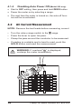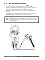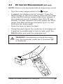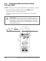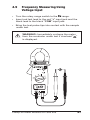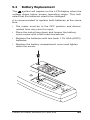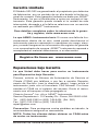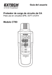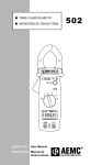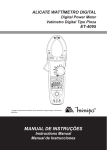
1
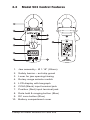
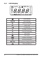
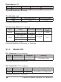
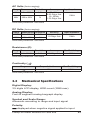
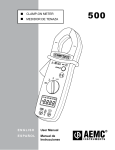
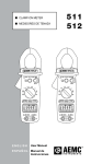
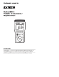
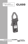
CLAMP-ON METER MEDIDORES DE TENAZA ENGLISH User Manual E S PA Ñ O L Manual de Instrucciones 501 503 Statement of Compliance Chauvin Arnoux®, Inc. d.b.a. AEMC® Instruments certifies that this instrument has been calibrated using standards and instruments traceable to international standards. We guarantee that at the time of shipping your instrument has met its published specifications. An NIST traceable certificate may be requested at the time of purchase, or obtained by returning the instrument to our repair and calibration facility, for a nominal charge. The recommended calibration interval for this instrument is 12 months and begins on the date of receipt by the customer. For recalibration, please use our calibration services. Refer to our repair and calibration section at www.aemc.com. Serial #: _ ________________________________ Catalog #: 2117.21 / 2117.22 Model #: 501/503 Please fill in the appropriate date as indicated: Date Received: ____________________________ Date Calibration Due: _______________________ Chauvin Arnoux®, Inc. d.b.a AEMC® Instruments www.aemc.com TABLE OF CONTENTS INTRODUCTION...................................... 4 1.1 International Electrical Symbols............5 1.2 Receiving Your Shipment......................5 1.3 Ordering Information.............................5 PRODUCT FEATURES.............................. 6 2.1 Model 501 Control Features.................6 2.2 Model 503 Control Features.................7 2.3 LCD Display..........................................8 SPECIFICATIONS.................................... 9 3.1 Electrical Specifications........................9 3.1.1 Model 501..................................9 3.1.2 Model 503................................10 3.2 Mechanical Specifications...................11 3.3 Environmental Specifications..............12 3.4 Safety Specifications . ........................12 OPERATION........................................... 13 4.1 Functions............................................13 4.1.1 Data Hold.................................13 4.1.2 Manual Range Mode (Model 503 only)............................13 4.1.3 (Relative) Zero Mode (Model 503 only) . ..........................13 4.1.4 Disabling Auto Power Off (Model 503 only)..................................... 14 4.2 AC Current Measurement...................14 4.3 AC Volt Measurement.........................15 2 Clamp-on Meter Models 501 and 503 4.4 4.5 4.6 4.7 4.8 4.9 DC Volt Measurement.........................16 DC Current Measurement (503 only).....17 Resistance Measurement...................18 Continuity Measurement.....................19 Frequency Measurement Using Current Input.............................20 Frequency Measuring Using .................. Voltage Input.......................................21 MAINTENANCE...................................... 22 5.1 Warning!..............................................22 5.2 Cleaning..............................................22 5.3 Battery Replacement..........................23 Repair and Calibration.........................................24 Technical and Sales Assistance..........................24 Limited Warranty.................................................25 Warranty Repairs.................................................25 Clamp-on Meter Models 501 and 503 3 CHAPTER 1 INTRODUCTION Warning ● Read the user manual before operating and follow all safety information. ● Only use the meter as specified in this user manual. ● Never use this meter on a circuit with voltages greater than 600Vrms @ 50/60Hz. ● Never measure current while the test leads are connected to the input jacks. ● Do not operate the meter if the body or test leads look damaged. ● Check the rotary range switch and make sure it is at the correct position before each measurement. ● Do not perform resistance and continuity test on a live circuit. ● Use extreme caution when measuring live systems with voltages greater than 60VDC or 30VAC. ● Use extreme care when working around bus bars and bare conductors. ● Do not use the meter in over range/overload conditions (OL). ● For accurate readings, change the battery when the symbol appears. 4 Clamp-on Meter Models 501 and 503 1.1 International Electrical Symbols This symbol signifies that the instrument is protected by double or reinforced insulation. This symbol on the instrument indicates a WARNING and that the operator must refer to the user manual for instructions before operating the instrument. In this manual, the symbol preceding instructions indicates that if the instructions are not followed, bodily injury, installation/sample and product damage may result. Risk of electric shock. The voltage at the parts marked with this symbol may be dangerous. 1.2 Receiving Your Shipment Upon receiving your shipment, make sure that the contents are consistent with the packing list. Notify your distributor of any missing items. If the equipment appears to be damaged, file a claim immediately with the carrier and notify your distributor at once, giving a detailed description of any damage. Save the damaged packing container to substantiate your claim. 1.3 Ordering Information Clamp-on Meter Model 501......................Cat. #2117.21 Includes meter, pair of test leads (red/black with probe tips), two 1.5V AAA batteries, soft carrying case and a user manual. Clamp-on Meter Model 503......................Cat. #2117.22 Includes meter, pair of test leads (red/black with probe tips), two 1.5V AAA batteries, soft carrying case and a user manual. Clamp-on Meter Models 501 and 503 5 CHAPTER 2 PRODUCT FEATURES 2.1 Model 501 Control Features 1 MODEL 501 CL AMP METER 2 600V CAT II 300V CAT III H 400A 8 HOLD 3 V V 9 Ω A OFF Hz ! 4 IEC 1010 600V CAT II 300V CAT III POLLUTION DEGREE 2 WARNING TO AVOID ELECTRIC SHOCK REMOVE ALL INPUTS BEFORE OPENING THE CASE 5 SIZE AAA 1.5V X 2 COM ! 6 CAT II 600V 7 PLEASE READ MANUAL FOR SAFETY 1. Jaw assembly - Ø 1.18" (28mm) 2. Safety barrier – anti-slip guard 3. Lever for jaw opening/closing 4. Rotary range selector switch 5. LCD display with bargraph 6. COM (Black) input terminal jack 7. Positive (Red) input terminal jack 8. Data hold button (Blue) 9. Battery compartment cover 6 Clamp-on Meter Models 501 and 503 2.2 Model 503 Control Features 1. Jaw assembly - Ø 1.18" (28mm) 2. Safety barrier – anti-slip guard 3. Lever for jaw opening/closing 4. Rotary range selector switch 5. LCD display with bargraph 6. COM (Black) input terminal jack 7. Positive (Red) input terminal jack 8. Data hold & ranging button (Blue) 9. DC zero button (Blue) 10. Battery compartment cover Clamp-on Meter Models 501 and 503 7 2.3 LCD Display AUTO 0 10 H 20 MK Hz 30 V A Ω 40 Low Battery AUTO Auto Range Manual Range Data Hold Continuity V Voltage Indicator A Current Indicator AC Inupt DC Input Polarity Indicator Analog Bargraph MK Hz Frequency Measurement Zero (Relative) 8 Clamp-on Meter Models 501 and 503 CHAPTER 3 SPECIFICATIONS Accuracy is provided under the following reference conditions: 23°C ±5°C, 45 to 75% RH, 3V supply, conductor centered, earth’s magnetic field, no external magnetic or electrical field, sine wave 50/60 Hz. Accuracy is expressed as ± [% of reading (Rdg) ± counts (cts)] 3.1 Electrical Specifications 3.1.1 Model 501 AC Amperes (Auto-ranging) Range Measurement Resolution Accuracy 40A 0.05 to 39.99A 0.01A 400A 40.0 to 400.0A 0.1A 50 to 60Hz: 1.9% of Rdg ± 5cts 60 to 500Hz: 2.5% of Rdg ± 5cts Overload protection: 600Arms AC Volts (Auto-ranging) Range Measurement Resolution Accuracy Protection 400V 0.5 to 399.9V 0.1V 600V 400 to 600V 1V 50 to 60Hz: 0.8% of Rdg ± 5cts 60 to 500Hz: 1.5% of Rdg ± 5cts 600Vrms Accuracy Protection 1% Rdg ± 2cts 600Vrms Input Impedance: 1MΩ DC Volts (Auto-ranging) Range Measurement Resolution 400V 0.2 to 399.9V 0.1V 600V 400 to 600V 1V Input Impedance: 1MΩ Clamp-on Meter Models 501 and 503 9 Resistance (Ω) Range Measurement Resolution 400Ω 0.2 to 399.9Ω 0.1Ω Accuracy Max Test Voltage 1% Rdg ± 2cts 1.5VDC Overload protection: 600Vrms Continuity ( ) Range Beeper Activation Max Test Voltage < 40Ω 1.5VDC Overload protection: 600Vrms Frequency (Hz) (Auto-ranging) Input Current Voltage Range Resolution Accuracy 20 to 3999 Hz 4.00 to 10.00 kHz 2 to 3999 Hz 1 Hz 10 Hz 1 Hz Min. Input Signal 0.1% Rdg ± 1ct 2Arms 4.00 to 39.99 kHz 10 Hz 5Vrms 40.0 to 399.9 kHz 100 Hz 0.1% Rdg ± 1ct Input Impedance: 1MΩ Overload protection: 600Vrms or 600Arms 3.1.2 Model 503 DC Amperes (Auto-ranging) Range Measurement Resolution 40A 0.10 to 39.99A 0.01A 400A 40.0 to 400.0A 0.1A Accuracy 2.5% Rdg ± 10cts Overload protection: 600Arms AC Amperes (Auto-ranging) Range Measurement Resolution Accuracy 40A 0.05 to 39.99A 0.01A 400A 40.0 to 400.0A 0.1A 50 to 60Hz: 1.5% Rdg ±10cts 60 to 500Hz: 2.5% Rdg ±10cts Overload protection: 600Arms 10 Clamp-on Meter Models 501 and 503 AC Volts (Auto-ranging) Range Measurement Resolution 400V 0.5 to 399.9V 0.1V 600V 400 to 600V 1V Accuracy Input Impedance 50 - 60Hz: 0.8% Rdg ± 5cts 60 - 500Hz: 1.5% Rdg ± 5cts 10MΩ Accuracy Input Impedance 1% Rdg ± 2cts 10MΩ Accuracy Max Test Voltage 1% Rdg ± 2cts 1.5VDC Overload protection: 600Vrms DC Volts (Auto-ranging) Range Measurement Resolution 400V 0.2 to 399.9V 0.1V 600V 400 to 600V 1V Overload protection: 600Vrms Resistance (Ω) Range Measurement Resolution 400Ω 0.2 to 399.9Ω 0.1Ω Overload protection: 600Vrms Continuity ( Range ) Beeper Activation Max Test Voltage < 40Ω 1.5VDC Overload protection: 600Vrms 3.2 Mechanical Specifications Digital Display: 3¾ digits LCD display, 4000-count (3999 max) Analog Display: Fast 42 segment analog bargraph display Symbol and Scale Range: Automatic according to range and input signal Polarity: displayed when negative signal applied to input Clamp-on Meter Models 501 and 503 11 Over Load: displayed when input signal exceeds range Sample Rate: 2 samples/sec for the digital display 20 samples/sec for the analog bargraph Power Supply: Two 1.5V AAA (LR03) batteries displayed when the battery Low Power Indication: is below the required voltage Battery Life: 100 hours approx (Model 501) 80 hours approx (Model 503) Auto Power Off: The meter will shut itself OFF if there is no activity for 30 minutes. Jaw Opening: 1.1" (28mm) Dimension (L x W x D): 7.60 x 1.97 x1.1" (193 x 50 x 28mm) Weight: 8.11 oz (230g) with batteries 3.3 Environmental Specifications Operating Temperature: 32° to 104°F (0° to 40°C), <80% RH, non-condensing Storage Temperature: 14° to 140°F (-10° to 60°C), <70% RH, battery removed Altitude: 2000m 3.4 Safety Specifications EN 61010, 600V, CAT II EN 61010, 300V, CAT III Pollution Degree: 2 12 Clamp-on Meter Models 501 and 503 CHAPTER 4 OPERATION 4.1 Functions 4.1.1 Data Hold • The last reading may be held on the display by pressing the Hold button. The symbol will be displayed. • When the held data is no longer needed, release the hold function by pressing the Hold button again. 4.1.2 Manual Range Mode (Model 503 only) • The Model 503 operates in an Auto-ranging mode (AUTO displayed) by default. Manual-ranging in V (400V, 600V), and A (40A, 400A) is available. Press and hold the RANGE button. When the range changes (decimal point shift), release the button. • The symbol is displayed in the manual range mode. • Press and hold the RANGE button for more than 2 seconds to re-enter the Auto-ranging mode. 4.1.3 (Relative) Zero Mode (Model 503 only) • Press the ZERO button to enter the Zero mode - the symbol turns on and the display is set to zero. • To view the offset value, press the ZERO button again. annunciator blinks and the memorized offset The value will be displayed. This value will be subtracted from the next measurement. • When the zero mode is activated, the meter automatically enters the manual range mode (the auto-range function will be disabled). • Press and hold down the to exit. ZERO button for 2 seconds Clamp-on Meter Models 501 and 503 13 4.1.4 Disabling Auto Power Off (Model 503 only) • Start in OFF setting, then press and hold ZERO button. • Power the meter on by selecting a range. • The next time the meter is turned on, the auto-off function will be re-activated. 4.2 AC Current Measurement NOTE: Remove the test leads before measuring current • Turn the rotary range switch to the range. • Press the lever to open the jaws. • Clamp the jaws around the conductor to be measured. • If reading is unstable and is hard to read, push the HOLD button and read the measurement. WARNING: If overload " " is displayed, unclamp the meter immediately . IN ST RU ME NT ® CL 501ER DELP MET MOAM S H 0A 40 T II CA T III 0V CA LD 60 0V HO 30 F A OF V V Ω 10 20 Hz 0 TO AU M II T CA 0V 60 ! A 00 20 CO 14 Clamp-on Meter Models 501 and 503 4.3 AC Volt Measurement WARNING: Maximum Input Voltage is 600V. Do not exceed this voltage to avoid electrical shock and/or damage to the instrument. • Turn the rotary range switch to the range. • Insert the red test lead to the red "+" input jack and the black lead to the black "COM" input jack. • Bring the test probe tips into contact with the test points. • If reading is unstable and is hard to read, push the HOLD button and read the measurement. WARNING: Immediately unclamp the meter from the conductor under test if overload " " is displayed. ® INSTRUMENTS MODEL 501 CL AMP METER 600V CAT II 300V CAT III 400A HOLD H V V Ω A OFF Hz AUTO 0 1100 V 10 COM ! CAT II 600V Clamp-on Meter Models 501 and 503 15 4.4 DC Volt Measurement • Turn the rotary range switch to the range. • Insert the red test lead to the red "+" input jack and the black lead to the black "COM" input jack. • Bring the test probe tips into contact with the test points. • If reading is unstable and is hard to read, push the HOLD button and read the measurement. WARNING: Immediately unclamp the meter from the conductor under test if overload " " is displayed. ® INSTRUMENTS MODEL 501 CL AMP METER 600V CAT II 300V CAT III 400A HOLD H V V Ω A OFF Hz AUTO 0 10 COM 120 V ! CAT II 600V 16 Clamp-on Meter Models 501 and 503 4.5 DC Current Measurement (503 only) NOTE: Remove the test leads before measuring current • Turn the rotary range switch to the range. • If needed, the display may be “zeroed”. Press the ZERO button to zero the reading. Note that the meter enters the 40A manual range mode when zeroed. If the measured current is greater than 40A (OL displayed), the user needs to manually select the 400A range (see Manual Range procedure § 4.1.2), and then zero the probe again. • Press the lever to open the jaws. • Clamp the jaws around the conductor to be measured. • If reading is unstable and is hard to read, push the HOLD button and read the measurement. WARNING: Immediately unclamp the meter from the conductor under test if overload " " is displayed. ® NT S 503 DEL ETER MOLAMP M C ME IN ST RU 400A T II CA T III CA 600V D 300V OL H H E NG RA 1 Sec ss Pre RO ZE V A Ω A FF O AUTO 0 5 00 A ! M CO Clamp-on Meter Models 501 and 503 II CAT0V C 60 17 4.6 Resistance Measurement • Turn the rotary range switch to the range. • Insert the red test lead to the red "+" input jack and the black lead to the black "COM" input jack. • Bring the test probe tips into contact with the sample under test. WARNING: Immediately unclamp the meter from the conductor under test if overload " " is displayed. WARNING: When making a resistance mea surement, make sure that the power is off (dead circuit), and that all capacitors in the measured circuit are fully discharged. ® INSTRUMENTS MODEL 501 CL AMP METER 600V CAT II 300V CAT III 400A HOLD H V V Ω A OFF 0 Hz 3 000 10 COM 20 Ω ! CAT II 600V 18 Clamp-on Meter Models 501 and 503 4.7 Continuity Measurement • Turn the rotary range switch to the range. • Insert red test lead to the red "+" input jack and the black lead to the black "COM" input jack. • Bring the test probe tips into contact with the sample under test. • If the resistance is less than 40Ω, the beeper emits a continuous sound. WARNING: Immediately unclamp the meter from the conductor under test if overload " " is displayed. WARNING: When testing continuity, make sure that there is no power in the tested sample or circuit (dead circuit). This may be checked by using the voltage functions. Clamp-on Meter Models 501 and 503 19 4.8 Frequency Measurement Using Current Input NOTE: Remove the test leads before measuring current • Turn the rotary range switch to the range. • Press the lever to open the jaws. • Clamp the jaws around the conductor to be measured. WARNING: Do not use both voltage and cur rent inputs at the same time when measuring frequency. This may be dangerous. Erroneous readings will occur if both inputs are used at the same time. 20 Clamp-on Meter Models 501 and 503 4.9 Frequency Measuring Using Voltage Input • Turn the rotary range switch to the range. • Insert red test lead to the red "+" input jack and the black lead to the black "COM" input jack. • Bring the test probe tips into contact with the sample under test. WARNING: Immediately unclamp the meter from the conductor under test if overload " " is displayed. Clamp-on Meter Models 501 and 503 21 CHAPTER 5 MAINTENANCE 5.1 Warning! • Remove the test leads on any input before opening the case. • Do not operate the clamp-on probe without a battery case cover. • To avoid electrical shock, do not attempt to perform any servicing unless you are qualified to do so. • To avoid electrical shock and/or damage to the instrument, do not get water or other foreign agents into the probe. 5.2 Cleaning • To clean the probe, wipe the case with a damp cloth and mild detergent. • Do not use abrasives or solvents. • Do not get water inside the case. This may lead to electrical shock or damage to the instrument. 22 Clamp-on Meter Models 501 and 503 5.3 Battery Replacement The symbol will appear on the LCD display when the voltage drops below proper operating range. This indicates that the batteries need to be changed. It is recommended to replace both batteries at the same time. • The meter must be in the OFF position and disconnected from any circuit or input. • Place the meter face down and loosen the battery cover screw with a flat head screwdriver. • Replace the batteries with two fresh 1.5V AAA (LR03) batteries. • Replace the battery compartment cover and tighten down the screw. Clamp-on Meter Models 501 and 503 23 Repair and Calibration To ensure that your instrument meets factory specifications, we recommend that it be submitted to our factory Service Center at one-year intervals for recalibration, or as required by other standards or internal procedures. For instrument repair and calibration: You must contact our Service Center for a Customer Service Authorization Number (CSA#). This will ensure that when your instrument arrives, it will be tracked and processed promptly. Please write the CSA# on the outside of the shipping container. If the instrument is returned for calibration, we need to know if you want a standard calibration, or a calibration traceable to N.I.S.T. (Includes calibration certificate plus recorded calibration data). Chauvin Arnoux®, Inc. d.b.a. AEMC® Instruments 15 Faraday Drive • Dover, NH 03820 USA Tel: (800) 945-2362 or (603) 749-6434 (Ext. 360) Fax: (603) 742-2346 or (603) 749-6309 [email protected] (Or contact your authorized distributor) Costs for repair, standard calibration, and calibration traceable to N.I.S.T. are available. NOTE: A CSA# must be obtained before returning any instrument. Technical and Sales Assistance If you are experiencing any technical problems, or require any assistance with the proper operation or application of your instrument, please call, mail, fax or e-mail our technical support hotline: Chauvin Arnoux®, Inc. d.b.a. AEMC® Instruments 200 Foxborough Blvd • Foxborough, MA 02035, USA Phone: (800) 343-1391 or (508) 698-2115 Fax: (508) 698-2118 [email protected] www.aemc.com NOTE: Do not ship Instruments to our Foxborough, MA address. 24 Clamp-on Meter Models 501 and 503 Limited Warranty The Model 501 and 503 are warranted to the owner for a period of one year from the date of original purchase against defects in manufacture. This limited warranty is given by AEMC® Instruments, not by the distributor from whom it was purchased. This warranty is void if the unit has been tampered with, abused or if the defect is related to service not performed by AEMC® Instruments. For full warranty coverage detail and registration, go to www.aemc.com What AEMC® Instruments will do: If a malfunction occurs within the one-year period, you may return the instrument to us for repair or replacement free of charge, provided we have your registration information on file or proof of purchase. AEMC® Instruments will, at its option, repair or replace the faulty material. REGISTER ONLINE AT: www.aemc.com Warranty Repairs What you must do to return an Instrument for Warranty Repair: First, request a Customer Service Authorization Number (CSA#) by phone or by fax from our Service Department (see address below), then return the instrument along with the signed CSA Form. Please write the CSA# on the outside of the shipping container. Return the instrument, postage or shipment pre-paid to: Chauvin Arnoux®, Inc. d.b.a. AEMC® Instruments Service Dept • 15 Faraday Dr • Dover, NH 03820 USA Tel: (800) 945-2362 or (603) 749-6434 (Ext. 360) Fax: (603) 742-2346 or (603) 749-6309 [email protected] Caution: To protect yourself against in-transit loss, we recommend you insure your returned material. NOTE: All customers must obtain a CSA# before returning any instrument. Clamp-on Meter Models 501 and 503 25 NOTES: 26 Clamp-on Meter Models 501 and 503 TABLA DE CONTENIDOS INTRODUCCIÓN.................................... 29 1.1 Símbolos Eléctricos Internacionales........... 30 1.2 Recepción de su embarque................30 1.3 Información para poner una orden......30 CARACTERÍSTICAS DEL PRODUCTO... 31 2.1 Características de Modelo 501...........31 2.2 Características de Modelo 503...........32 2.3 Características de la pantalla LCD.....33 ESPECIFICACIONES.............................. 34 3.1 Especificaciones Eléctricas.................34 3.1.1 Modelo 501..............................34 3.1.2 Modelo 503..............................35 3.2 Especificaciones Mecánicas...............36 3.3 Especificaciones Ambientales.............37 3.4 Especificaciones de Seguridad...........37 OPERACIÓN........................................... 38 4.1.1 Mantener Lectura.....................38 4.1.2 Modo de Rango Manual (sólo Modelo 503)...........................38 4.1.3 Modo Cero (Relativo) (sólo Modelo 503)...........................38 4.1.4 Deshabilitar el Apagado Automático (sólo Modelo 503)........39 4.2 Medición de Corriente CA...................40 4.3 Medición de Volt CA............................41 4.4 Medición de Volt CD...........................42 Medidores de Tenaza Modelos 501/503 27 4.5 4.6 4.7 4.8 4.9 Medición de Corriente CD (Modelo 503). ..........................................43 Medición de Resistencia.....................44 Prueba de Continuidad.......................45 Medición de Frecuencia usando la entrada de corriente........................46 Medición de Frecuencia usando la entrada de voltaje............................47 MANTENIMIENTO.................................. 48 5.1 Advertencia!........................................48 5.2 Limpieza..............................................48 5.3 Reemplazo de la Batería....................49 Reparación y Calibración....................................50 Asistencia Técnica y de Ventas...........................50 Garantía Limitada................................................51 Reparaciones bajo Garantía...............................51 28 Medidores de Tenaza Modelos 501/503 CAPÍTULO 1 INTRODUCCIÓN Advertencia • Lea el manual de usuario antes de operar el instrumento y siga todas las instrucciones de seguridad. • Use el medidor sólo como se especifica en este manual de usuario. De otra forma se puede dañar la protección del instrumento. • Nunca utilice este medidor en un circuito con voltajes superiores a 600Vrms @ 50/60Hz. • Nunca mida corriente mientras los cables de prueba estén conectados a las entradas. • No opere el medidor si la carcasa o los cables de prueba están dañados. • Revise el selector de rango rotatorio y asegúrese que está en la posición correcta antes de cada medición. • No realice pruebas de resistencia ni de continuidad en un circuito vivo. • Sea extremadamente cuidadoso cuando mida en circuitos vivos con voltajes superiores a 60VCD o 30VCA. • Tenga mucho cuidado al trabajar cerca de barras bus y conductores desnudos. • No utilice el medidor fuera de rango o en condiciones de sobrecarga (OL). • Para evitar lecturas erróneas, cambie la batería cuando aparece el símbolo . Medidores de Tenaza Modelos 501/503 29 1.1 Símbolos Eléctricos Internacionales Este símbolo significa que el instrumento esta protegido por un doble aislamiento o un aislamiento reforzado. Utilice piezas de repuesto especificadas por AEMC cuando repare el instrumento. Este símbolo en el instrumento significa ADVERTENCIA en este caso consulte el manual de instrucciones antes de utilizar el aparato. En el supuesto que aparezca esta señal, significara no se han seguido las instrucciones de uso, si no se respetan o realizan correctamente, pueden ocasionar un accidente corporal o dañar el equipo o las instalaciones. Riesgo de choque eléctrico. Los componentes marcados con este símbolo pueden ser peligrosos. 1.2 Recepción de su embarque Luego de recibido su embarque, asegúrese que el contenido coincide con la guía de despacho. Avise a su distribuidor sobre cualquier parte faltante. Si el equipo aparece dañado, presente un reclamo inmediatamente al transportador y avise inmediatamente a su distribuidor, dando una descripción detallada de los daños. Conserve el empaque dañado para respaldar su reclamo. No utilice un instrumento que aparezca dañado. 1.3 Información para poner una orden Medidores de Tenaza Modelo 501........... Cat. #2117.21 Incluye Manual de usuario, cables de prueba, dos baterías AAA de 1.5V, Estuche de Trasporte Blando. Medidores de Tenaza Modelo 503........... Cat. #2117.22 Incluye Manual de usuario, cables de prueba, dos baterías AAA de 1.5V, Estuche de Trasporte Blando. 30 Medidores de Tenaza Modelos 501/503 CAPÍTULO 2 CARACTERÍSTICAS DEL PRODUCTO 2.1 Características de Modelo 501 1 MODEL 501 CL AMP METER 2 600V CAT II 300V CAT III H 400A 8 HOLD 3 V V 9 Ω A OFF Hz ! 4 IEC 1010 600V CAT II 300V CAT III POLLUTION DEGREE 2 WARNING TO AVOID ELECTRIC SHOCK REMOVE ALL INPUTS BEFORE OPENING THE CASE 5 SIZE AAA 1.5V X 2 COM ! 6 CAT II 600V 7 PLEASE READ MANUAL FOR SAFETY 1. Tenaza - Ø 1.18" (28mm) 2. Barrera de seguridad protección anti-deslizante 3. Palanca para abrir/cerrar la tenaza 4. Selector de rango rotatorio 5. Pantalla LCD con gráfico de barras 6. Terminal de entrada COM (Negro) 7. Terminal de entrada Positivo (Rojo) 8. Botón para mantener lectura (Azul) 9. Cubierta del compartimiento de batería Medidores de Tenaza Modelos 501/503 31 2.2 Características de Modelo 503 1. Tenaza - Ø 1.18" (28mm) 2. Barrera de seguridad protección anti-deslizante 3. Palanca para abrir/cerrar la tenaza 4. Selector de rango rotatorio 5. Pantalla LCD con gráfico de barras 6. Terminal de entrada COM (Negro) 7. Terminal de entrada Positivo (Rojo) 8. Botón para mantener lectura & elegir rango (Azul) 9. Botón de cero CD (Azul) 10. Cubierta del compartimiento de batería 32 Medidores de Tenaza Modelos 501/503 2.3 Características de la pantalla LCD AUTO 0 10 H 20 MK Hz 30 V A Ω 40 Batería baja AUTO Auto Rango Rango manual Mantener Lectura Continuidad con bíper V Función Voltaje seleccionada A Función Corriente seleccionada Entrada CA Entrada CD Indicador de Polaridad Gráfico de Barras analógico MK Hz Medición de frecuencia (MHz, kHz) Cero (Relativo) Medidores de Tenaza Modelos 501/503 33 CAPÍTULO 3 ESPECIFICACIONES La exactitud está dada bajo las siguientes condiciones de referencia: 23°C ±5°C, 45 a 75% HR, alimentación de 3V, conductor centrado, campo magnético terrestre, sin campos magnéticos o eléctricos externos, onda sinusoidal 50/60 Hz. La exactitud se expresa como ± [% de lectura (Lect.) ± cuentas (cts)]. 3.1 Especificaciones Eléctricas 3.1.1 Modelo 501 Amperes CA (Auto Rango) Rango Medición Resolución Exactitud 40A 0.05 - 39.99A 0.01A 400A 40.0 – 400.0A 0.1A 50 - 60Hz: 1.9% Lect.±5 cts 60 - 500Hz: 2.5% Lect.±5 cts Protección de Sobrecarga: 600 Arms Volts CA (Auto Rango) Rango Medición Resolución Exactitud 400V 0.5 - 399.9V 0.1V 600V 400 - 600V 1V 50 - 60Hz: 0.8% Lect..±5 cts 60 - 500Hz: 1.5% Lect..±5 cts Impedancia de Entrada 1MΩ Protección de Sobrecarga: 600 Vrms Volts CD (Auto Rango) Rango Medición Resolución Exactitud Impedancia de Entrada 400V 0.2 - 399.9V 0.1V 600V 400 - 600V 1V 1% Lect. ±2 cts 1MΩ Protección de Sobrecarga: 600 Vrms 34 Medidores de Tenaza Modelos 501/503 Resistencia (Ω) Rango Medición Resolución Exactitud Voltaje de Prueba 0.1 Ω 1% Lect. ± 2 cts 1.5V CD Máx. 400 Ω 0.2 - 399.9 Ω Protección de Sobrecarga: 600 Vrms Continuidad ( ) Rango Activación del Bíper Voltaje de Prueba Máx. < 40 Ohm 1.5 V CD Protección de Sobrecarga: 600 Vrms Frecuencia (Hz) (Auto-ranging) Entrada Corriente Voltaje Rango Resolución Exactitud 20 - 3999 Hz 4.00 - 10.00 kHz 2 - 3999 Hz 1 Hz 10 Hz 1 Hz Señal de Entrada Min. 0.1% Lect. ± 1 ct 2Arms 4.00 - 39.99 kHz 10 Hz 5Vrms 40.0 - 399.9 kHz 100 Hz 0.1% Lect. ± 1 ct Impedancia de Entrada: 1MΩ Protección de Sobrecarga: 600 Vrms o 600 Arms 3.1.2 Modelo 503 Amperes CD (Auto Rango) Rango Medición 40A 0.10 - 39.99A 400A 40.0 - 400.0A Resolución 0.01A 0.1A Exactitud 2.5% Lect. ± 10 cts Protección de Sobrecarga: 600 Arms Amperes CA (Auto Rango) Rango Medición Resolución 40A 0.05 - 39.99A 0.01A 400A 40.0 - 400.0A 0.1A Exactitud 50 - 60Hz: 1.5% Lect.± 10 cts 60 - 500Hz: 2.5% Lect. ± 10 cts Protección de Sobrecarga: 600 Arms Medidores de Tenaza Modelos 501/503 35 Volts CA (Auto Rango) Rango Medición Resolución Exactitud Impedancia de Entrada 400V 0.5 - 399.9V 0.1V 600V 400 - 600V 1V 50 - 60Hz: 0.8% Lect.± 5 cts 60 - 500Hz: 1.5% Lect. ± 5 cts 10 MΩ Protección de Sobrecarga: 600 Vrms Volts CD (Auto Rango) Rango Medición Resolución 400V 0.2 - 399.9V 0.1V 600V 400 - 600V 1V Exactitud Impedancia de Entrada 1% Lect.± 2 cts 10MΩ Protección de Sobrecarga: 600 Vrms Resistencia (Ω) Rango Medición 400 Ω 0.2 - 399.9 Ω Resolución Exactitud Voltaje de Prueba 0.1 Ω 1% Lect. ± 2 cts 1.5V CD Máx. Protección de Sobrecarga: 600 Vrms Continuidad ( Rango ) Activación del Bíper Voltaje de Prueba < 40 Ohm 1.5 V CD Máx. Protección de Sobrecarga: 600 Vrms 3.2 Especificaciones Mecánicas Pantalla Digital: Pantalla LCD con dígitos de 3 3/4, 4000 cuentas (lectura máx. 3999) Pantalla Analógica: Presentación rápida en gráfico de barras de 42 segmentos Símbolos y rangos de Escala: Automáticos según rango y señal de entrada 36 Medidores de Tenaza Modelos 501/503 Polaridad: Al aplicar una señal negativa a la entrada se muestra Sobrecarga: Cuando la señal de entrada excede el rango se muestra Velocidad de Muestreo: 2 muestras/seg. para la pantalla digital 20 muestras/seg. para el gráfico de barras analógico Alimentación: Dos baterías AAA de 1.5V Indicador de Baja Energía: Cuando el voltaje de la batería está por debajo de lo requerido se muestra Apagado Automático: El medidor se apaga por si solo, si no se acciona ningún botón o el selector rotatorio durante 30 minutos Abertura de la tenaza: 1.1" (28mm) Dimensiones (Largo x Ancho x Alto): 7.60 x 1.97 x1.1" (193 x 50 x 28mm) Peso: 230g, (8.11oz) con baterías 3.3 Especificaciones Ambientales Altura: 2000 metros. Temp. de Operación: 0°C - 40°C, <80% HR, no-condensante Temp. de Almacenamiento: -10°C - 60°C, <70% HR, sin baterías 3.4 Especificaciones de Seguridad EN 61010, 600V, CAT II EN 61010, 300V, CAT III Contaminación Grado: 2 Medidores de Tenaza Modelos 501/503 37 CAPÍTULO 4 OPERACIÓN 4.1.1 Mantener Lectura • La última lectura puede mantenerse en la pantalla presionando el botón Hold. Se mostrará el símbolo • Cuando no necesite más el dato, libere la función mantener lectura presionando el botón Hold nuevamente. 4.1.2 Modo de Rango Manual (sólo Modelo 503) • El Modelo 503 opera en forma preestablecida en modo auto rango (se muestra AUTO en pantalla). Existe un modo de rango manual para V (400V, 600V), y A (40A, 400A). • Presione y mantenga presionado el botón RANGE. Cuando cambie el rango (se desplaza el punto decimal), libere el botón. • En el modo rango manual se muestra el símbolo • Presione y mantenga presionado el botón RANGE por más de 2 segundos para volver al modo AUTO rango. 4.1.3 Modo Cero (Relativo) (sólo Modelo 503) • Presione el botón Cero - se enciende el símbolo cero. para entrar al modo Cero y la pantalla se ajusta a • Para ver el valor del desplazamiento del cero, preparpadea sione el botón nuevamente. El símbolo y se visualiza el valor del desplazamiento memorizado. Este valor se restará de la siguiente medición. 38 Medidores de Tenaza Modelos 501/503 • Al activar el modo cero, el medidor automáticamente entra al modo manual (se deshabilitará la función auto rango) . • Presione y mantenga presionado el botón cero durante 2 segundos para salir. 4.1.4 Deshabilitar el Apagado Automático (sólo Modelo 503) • Comience en la posición OFF, luego presione y mantenga presionado el botón ZERO. • Encienda el medidor seleccionado un rango. • La próxima vez que el medidor sea encendido, se reactivará el apagado automático. Medidores de Tenaza Modelos 501/503 39 4.2 Medición de Corriente CA • Gire el selector de rango rotatorio a la posición . • Presione la palanca para abrir la tenaza. • Coloque la tenaza alrededor del conductor que desea medir. • Retire inmediatamente el medidor desde el conductor que se mide si aparece "OL". • Si la lectura es inestable y difícil de leer, presione el botón HOLD y tome la lectura. Nota: Retire los cables de prueba antes de medir corriente. IN ST RU ME NT ® CL 501ER DELP MET MOAM S H 0A 40 T II CA T III 0V CA LD 60 0V HO 30 F A OF V V Ω 10 20 Hz 0 TO AU M II T CA 0V 60 ! A 00 20 CO 40 Medidores de Tenaza Modelos 501/503 4.3 Medición de Volt CA • Gire el selector de rango rotatorio a la posición . • Inserte el cable de prueba rojo en la entrada "+"roja y el cable de prueba negro en la entrada "COM" negra. • Haga contacto con las puntas en los puntos de medición. • Retire inmediatamente las puntas de prueba desde el circuito que se mide si aparece "OL". • Si la lectura es inestable y difícil de leer, presione el botón HOLD y tome la lectura. ® INSTRUMENTS MODEL 501 CL AMP METER 600V CAT II 300V CAT III 400A HOLD H V V Ω A OFF Hz AUTO 0 1100 V 10 COM ! CAT II 600V Medidores de Tenaza Modelos 501/503 41 4.4 Medición de Volt CD • Gire el selector de rango rotatorio a la posición . • Inserte el cable de prueba rojo en la entrada "+"roja y el cable de prueba negro en la entrada "COM" negra. • Haga contacto con las puntas en los puntos de medición. • Retire inmediatamente las puntas de prueba desde el circuito que se mide si aparece "OL". • Si la lectura es inestable y difícil de leer, presione el botón HOLD y tome la lectura. ® INSTRUMENTS MODEL 501 CL AMP METER 600V CAT II 300V CAT III 400A HOLD H V V Ω A OFF Hz AUTO 0 10 COM 120 V ! CAT II 600V 42 Medidores de Tenaza Modelos 501/503 4.5 Medición de Corriente CD: (Modelo 503) • Gire el selector de rango rotatorio a la posición . • Se puede ajustar la lectura a cero si es necesario. Presione el botón Cero para ajustar la lectura a cero. Note que el medidor entra al rango manual de 40A al ajustar la lectura a cero. Si la corriente que se mide es mayor que 40A (se muestra OL en pantalla), el usuario debe seleccionar manualmente el rango 400A (vea § 4.1.2 para Rango Manual) y volver a ajustar el cero del medidor. • Presione la palanca para abrir la tenaza. • Coloque la tenaza alrededor del conductor que desea medir. • Retire inmediatamente el medidor desde el conductor que se mide si aparece "OL". • Si la lectura es inestable y difícil de leer, presione el botón HOLD y tome la lectura. Nota: Retire los cables de prueba antes de medir corriente. ® NT S 503 DEL ETER MOLAMP M C ME IN ST RU 400A T II CA T III CA 600V D 300V OL H H E NG RA 1 Sec ss Pre RO ZE V A Ω A F OF AUTO 0 5 00 A ! M CO Medidores de Tenaza Modelos 501/503 II CAT0V C 60 43 4.6 Medición de Resistencia • Gire el selector de rango rotatorio a la posición . • Inserte el cable de prueba rojo en la entrada "+"roja y el cable de prueba negro en la entrada "COM" negra. • Haga contacto con las puntas de prueba en la muestra a medir. • Si aparece "OL", la resistencia excede el rango de medición o el circuito está abierto. Nota: Al hacer una medición de resistencia, asegúrese que no hay energía (circuito muerto). También es importante que todos los condensadores del circuito que se mide estén totalmente descargados. ® INSTRUMENTS MODEL 501 CL AMP METER 600V CAT II 300V CAT III 400A HOLD H V V Ω A OFF 0 Hz 3 000 10 20 COM ! Ω CAT II 600V 44 Medidores de Tenaza Modelos 501/503 4.7 Prueba de Continuidad • Gire el selector de rango rotatorio a la posición . • Inserte el cable de prueba rojo en la entrada "+"roja y el cable de prueba negro en la entrada "COM" negra. • Haga contacto con las puntas de prueba en la muestra a medir. • Si la resistencia es menor que 40Ω, el bíper emite un sonido continuo. • Si aparece "OL ", la resistencia excede el rango de medición o el circuito está abierto. Nota: Al probar continuidad, asegúrese que no hay energía en la muestra o en el circuito bajo prueba (circuito muerto). Esto puede comprobarse usando las funciones de voltaje. Medidores de Tenaza Modelos 501/503 45 4.8 Medición de Frecuencia usando la entrada de corriente • Gire el selector de rango rotatorio a la posición . • Presione el gatillo para abrir la tenaza. • Coloque la tenaza alrededor del conductor a medir. • Si la lectura es inestable y difícil de leer, presione el botón HOLD y tome la lectura. Nota: Desconecte los cables de prueba antes de medir frecuencia a través del modo corriente (tenaza). ¡Advertencia!: Al medir frecuencia no utilice las entradas de voltaje y de corriente simultáneamente. Esto puede ser peligroso. Si se usan ambas entradas al mismo tiempo se producirán lecturas erróneas. 46 Medidores de Tenaza Modelos 501/503 4.9 Medición de Frecuencia usando la entrada de voltaje • Gire el selector de rango rotatorio a la posición . • Inserte el cable de prueba rojo en la entrada "+"roja y el cable de prueba negro en la entrada "COM" negra. • Haga contacto con las puntas de prueba en el circuito a medir. • Retire inmediatamente las puntas de prueba desde el circuito que se mide si aparece "OL". • Si la lectura es inestable y difícil de leer, presione el botón HOLD y tome la lectura. Medidores de Tenaza Modelos 501/503 47 CAPÍTULO 5 MANTENIMIENTO 5.1 Advertencia! • Retire los cables de prueba de las entradas antes de abrir la caja. No opere el medidor de tenaza sin la cubierta del compartimiento de la batería. • Para evitar un choque eléctrico, no intente realizar ninguna reparación si no está calificado para hacerla. • Para evitar un choque eléctrico y/o daño al instrumento no permita que entre agua u otro agente extraño al interior del medidor. 5.2 Limpieza • Para limpiar el medidor, frote la caja con un paño húmedo y un detergente suave. No use abrasivos ni solventes. • No permita que entre agua dentro de la caja. Esto puede conducir a un choque eléctrico o dañar el instrumento. 48 Medidores de Tenaza Modelos 501/503 5.3 Reemplazo de la Batería • Los medidores de tenaza Modelos 501 y 503 son alimentados por dos baterías tipo AAA de 1.5V. Cuando el voltaje de alimentación cae por debajo del rango de operación apropiado aparece en la pantalla LCD el símbolo Este indica que se debe reemplazar la batería. Se recomienda reemplazar ambas baterías simultáneamente. • El medidor debe estar en la posición OFF y desconectado de cualquier circuito o entrada. • Coloque el medidor cara abajo y suelte el tornillo de la cubierta de la batería con un destornillador de paleta. • Reemplace las baterías viejas por dos baterías nuevas de tamaño AAA de 1.5V. • Reponga la tapa del compartimiento de batería y apriete el tornillo. . Medidores de Tenaza Modelos 501/503 49 Reparación y Calibración Para asegurar que su instrumento cumple con las especificaciones de fábrica, recomendamos que sea enviado al Centro de Servicio de la fábrica para re-calibración, anualmente o según lo requieran otros estándares o procedimientos internos. Para la reparación y calibración del instrumento: Usted debe contactar nuestro Centro de Servicio para obtener un Número de Autorización de Servicio al Cliente (CSA#). Esto le asegurará que cuando llegue su instrumento, será ingresado y procesado con prontitud. Por favor escriba el CSA# en el exterior del envase. . Si el instrumento se envía para calibración, necesitamos saber si desea una calibración estándar o una calibración según N.I.S.T. (incluye certificado de calibración más registro de los datos de calibración). Chauvin Arnoux®, Inc. d.b.a. AEMC® Instruments 15 Faraday Drive • Dover, NH 03820 USA Tel: (800) 945-2362 or (603) 749-6434 (Ext. 360) Fax: (603) 742-2346 or (603) 749-6309 [email protected] (O contacte su distribuidor autorizado) Los Costos de reparación, calibración estándar y calibración según N.I.S.T. están disponibles. NOTA: Todos los clientes deben obtener un CSA# antes de enviar un instrumento. Asistencia Técnica y de Ventas Si tiene cualquier problema técnico o necesita ayuda para operar correctamente su instrumento o en sus aplicaciones, por favor llame, escriba, envíe un fax o correo electrónico a nuestro soporte técnico: Chauvin Arnoux®, Inc. d.b.a. AEMC® Instruments 200 Foxborough Blvd • Foxborough, MA 02035, USA Phone: (800) 343-1391 or (508) 698-2115 Fax: (508) 698-2118 [email protected] www.aemc.com NOTA: No envíe Instrumentos a nuestra dirección en Foxborough, MA. 50 Medidores de Tenaza Modelos 501/503 Garantía Limitada El Modelo 501/503 es garantizado al propietario por defectos de fabricación, por un período de un año desde la fecha original de compra. Esta garantía limitada es dada por AEMC® Instruments, no por el distribuidor a quien se compró el instrumento. Esta garantía queda viciada si la unidad ha sido intervenida, abusada o si la falla se relaciona con un servicio no realizado por AEMC® Instruments. Para detalles completos sobre la cobertura de la garantía y registro, visite www.aemc.com Lo que AEMC® Instruments hará: Si ocurre una falla de funcionamiento dentro de un año, usted puede devolvernos el instrumento para su reparación o reemplazo sin cargo, siempre y cuando tengamos su información de registro de garantía o un comprobante de compra. AEMC® Instruments reparará o reemplazará el material defectuosos, a su discreción. Registro En línea en: www.aemc.com Reparaciones bajo Garantía Lo que Usted debe hacer para enviar un Instrumento para Reparación bajo Garantía: Primero, solicite un Número de Autorización de Servicio al Cliente (CSA#) por teléfono o por fax a nuestro Departamento de Servicio (vea la dirección abajo), luego envíe el instrumento junto con el formulario CSA firmado. Por favor escriba el CSA# en el exterior del envase. Envíe el instrumento con el franqueo o flete prepagado a: Chauvin Arnoux®, Inc. d.b.a. AEMC® Instruments Service Department • 15 Faraday Dr • Dover, NH 03820 USA Tel: (800) 945-2362 or (603) 749-6434 (Ext. 360) Fax: (603) 742-2346 or (603) 749-6309 [email protected] Precaución: Para protegerse contra pérdidas en tránsito, le recomendamos asegurar su mercadería. NOTA: Todos los clientes deben obtener un CSA# antes de enviar un instrumento. Medidores de Tenaza Modelos 501/503 51 NOTAS: 52 Medidores de Tenaza Modelos 501/503 11/10 99-MAN 100163 v4 Chauvin Arnoux®, Inc. d.b.a. AEMC® Instruments 15 Faraday Drive • Dover, NH 03820 USA www.aemc.com