1
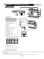
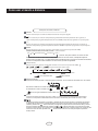
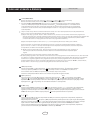
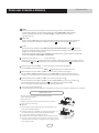
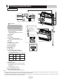
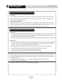
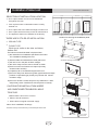
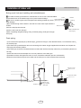
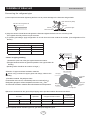
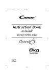
Tipo Consola
Aire Acondicionado
Manual de usuario
Aire Acondicionado Residencial
Gracias por elegir nuestro aire acondicionado, para un correcto funcionamiento por favor lea detenidamente este manual antes de instalar o utilizar
el equipo y guárdelo para futuras consultas.
INDICE
MANUAL DE USUARIO
1.
Nombres y funciones de las partes..................................................................................................... 1
2.
Como usar el mando a distancia.......................................................................................................... 2
3.
Mantenimiento
...................................................................................................................................... 6
4.
Guía funcionamiento............................................................................................................................ 9
5.
Consejos de uso................................................................................................................................. 10
6.
Precauciones
....................................................................................................................................... 11
7.
Antes de llamar al servicio técnico..................................................................................................... 12
GRACIAS POR SELECCIONAR NUESTROS PRODUCTOS
Uno de los beneficios que le esperan con su nuevo aire acondicionado, no
es solo comodidad sino también salud. Este manual de usuario explica
todas las características tecnológicas y de comodidad que esta unidad ofrece. Además, le proporciona información vital para el mantenimiento, el servicio y el ahorro en el funcionamiento. Dedique los siguientes minutos a
descubrir como conseguir el comfort y el ahorro en el funcionamiento de su
aire condicionado.
Las figuras de este manual pueden ser distintas a los materiales, por favor tome
como referencia la unidad real.
NOMBRES Y FUNCIONES DE LAS PARTES
MANUAL DE USUARIO
UNIDAD INTERIOR
1
3
2
6
8
9
11
10
12
13
7
4
14
15
2
ATENCION
Antes de abrir el panel frontal asegúrese de
parar el funcionamiento y apagar el interruptor.
No toque las partes de metal del interior de la
unidad interior, ya que puede causar daños.
1. Apatito de Titanio Fotocatalítico
Filtro Purificador de Aire:
Selección del interruptor de salida de aire
•
Esta posición saca aire por la salida
superior solamente.
•
Este ajuste decide automáticamente la salida de aire
dependiéndo del modo y de las
condiciones.
• Estos filtros están añadidos en el interior de los
filtros de aire.
2. Salida de Aire
3. Pantalla
4. Panel frontal
5. Deflectores (aspas verticales)
5
16
• Este ajuste está recomendado.
17
• La unidad es enviada desde
la fábrica con este ajuste.
• Los deflactores están dentro de la salida de aire.
6. Entrada de aire
7. Filtro de aire
8. Tapa (aspas horizontales)
9. Luz del modo Frío
10. Luz del modo Calor
11. Luz del modo Deshumidificador
12. Luz de funcionamiento
13. Pantalla LED
14. Interruptor ON/OFF de la unidad interior:
Abriendo el panel frontal
Terminal electrónica
de la unidad interior
N(1) 2
BU
BK
3
BN
AMARILLO
VERDE
• Presione este interruptor una vez para encender el aparato.
Presiónelo una vez más para pararlo.
• El modo de operación se muestra en la siguiente tabla.
Modelo
Modo
SOLO FRIO COOL
Ajuste de Flujo de aire
temperatura
25ºC
AUTO
BOMBA DE
25ºC
AUTO
AUTO
CALOR
• Este interruptor es útil cuando no se dispone del mando
a distancia.
15.Receptor de señal:
• Recibe señales del mando a distancia.
• Cuando la unidad recibe una señal, oirá un pitido corto.
•Cuando se modifica la configuración, oriá un pitido corto.
16.Interruptor de selección de salida de aire.
17.Sensor de la temperatura ambiente:
•Identifica la temperatura de alrededor de la unidad.
ATENCION:
① Si el cable de alimentación está dañado, éste debe ser remplazado por el fabricante, quién se lo haya proporcionado o personas calificadas similares con
tal de evitar riesgos.
② El aparato debe ser instalado acorde con la regulación eléctrica nacional.
③ El interruptor general debe tener una separación de por lo menos 3 milímetros y debería estar conectado a un cableado fijo.
1
Como usar el mando a distancia
MANUAL DE USUARIO
Descripción del mando a distancia
ON/OFF
1
Presiónelo para encender o apagar el aparato.
2
- : Presiónelo para reducir la temperatura.
3
+ : Presiónelo para aumentar la temperatura.
MODE
4
1
3
2
Presiónelo para seleccionar el modo de operación.
(AUTO/FRÍO/DESHUMIDIFICADOR/VENTILADOR/CALOR).
5
FAN
6
SWING
Presiónelo para ajustar la velocidad del ventilador.
Presiónelo para ajustar el ángulo de oscilación.
I FEEL
7
/
8
Presiónelo para ajustar la función SALUD o AIRE.
4
5
9
SLEEP
6
7
10
TEMP
8
9
11
QUIET
10
11
12
13
14
15
16
Presiónelo para ajustar el modelo la función QUIET.
12
CLOCK
Presiónelo para ajustar el reloj.
13
T-ON T-OFF
Presiónelo para ajustar el temporizador auto-off/auto-on.
14
TURBO
15
LIGHT
Presiónelo para encender/apagar la luz.
16
2
X-FAN
Como usar el mando a distancia
MANUAL DE USUARIO
Descripción del mando a distancia
1 ON/OFF :
P resione este botón para encender la unidad. Presiónelo de nuevo para apagarla.
2
Presione este botón para reducir la temperatura programada. Manteniéndolo pulsado más de 2 segundos, se
reduce la temperatura programada rápidamente. En modo AUTO, la temperatura programada no se puede ajustar.
3
+:
Presione este botón para aumentar la temperatura programada. Manteniéndolo pulsado más de 2 segundos, se
aumenta la temperatura programada rápidamente. En modo AUTO, la temperatura programada no se puede ajustar.
4 MODE :
Cada vez que presione este botón, un modo es seleccionado en una secuencia que va desde AUTO,
FRIO,DESHUMIDIFICADOR, VENTILADOR y CALOR *, como se muestra:
AUTO
FRIO
DESHUMIDIFICADOR
VENTILADOR
CALOR
*
* Atención: Solo para modelos con función de calor
Después del encendido, el modo AUTO está predeterminado. En el modo AUTO, la temperatura fijada no
aparecerá en la pantalla LCD, y la unidad seleccionará automáticamente el modo de funcionamiento adecuado
acorde con la temperatura de la habitación con tal de hacer que ésta sea agradable.
:
5 FAN (ventilador):
Este botón se usa para ajustar la velocidad del ventilador en una secuencia que va desde AUTO,
,
,
hasta
,
, y después nuevamente vuelve a Auto.
Auto
Velocidad Baja
Velocidad Baja-Media
Velocidad Media
Velocidad Media-Alta
6
Velocidad Alta
SWING (oscilante):
Presione este botón para alzar o bajar el ángulo de oscilación, el cual cambia circularmente como se muestra:
OFF
Este mando a distancia es universal. Si algun comando
la unidad llevará a cabo el comando como
,
o
se envía,
indica que la guia de deflectores oscila de este modo:
7 I FEEL:
Presione este botón para activar la función I FEEL. La unidad ajustará automáticamente la temperatura
acorde con la temperatura detectada.Presione este botón nuevamente para cancelar la función I FEEL.
8
/
Presione éste botón para lograr el encendido y apagado de las funciones de salud y recolección de residuos
en estado de funcionamiento. Presione este botón por primera vez para iniciar la función de recolección de
residuos; pantalla .LCD “ ”. Presione el botón por segunda vez para iniciar las funciones de salud y de recolección de residuos simultáneamente; pantalla LCD” “ y ” “. Presione este botón por tercera vez para salir
de las funciones de salud y de recolección de residuos simultaneamente. Presione el botón por cuarta vez para
activar la función de salud; pantalla LCD ” “. Presione este botón una vez más para repetir la operación
de aquí arriba.
3
Como usar el mando a distancia
9
●
●
●
●
MANUAL DE USUARIO
SLEEP (MODO NOCHE) :
Presione este botón para seleccionar Sleep 1(
), Sleep 2, (
), Sleep 3 (
) y para cancelar Sleep.
Cuando encienda la unidad, el modo Sleep estará cancelado de forma predeterminada.
En el modo CALOR y DESHUMIDIFICADOR, Sleep 1 es modo 1: el estado sleep después de estar en funcionamiento durante
una hora , la unidad principal de ajuste de temperatura incrementará 1℃ y la temperatura fijada 2 ℃ . La unidad funcionará
a esta temperatura. En el modo Heat: el estado sleep después de estar en funcionamiento durante una hora, la temperatura
se reducirá 1 ℃ . Al cabo de una hora más, la temperatura fijada se reducirá 1℃ más y después la unidad seguirá funcionando
a esta temperatura.
S leep 2 és modo sleep 2. El aire acondicionado funcionará acorde con la curva de temperatura modo noche predeterminada.
Sleep 3- la curva modo noche fijada bajo el modo Sleep modo DIY:
(1) Bajo el modo Sleep 3, presione el botón “Turbo” durante un rato, entonces el control remoto entrarará en la programación
del modo noche. Entonces, el mando a distancia mostrará las letras “1hour” (1 hora), y la ranura de la temperatura programada “88”
mostrará la temperatura correspondiente a la última curva del modo noche programada y parpadeará. (La primera entrada
se mostrará de acuerdo con la programación inicial de la curva programada en la fábrica).
(2) Ajuste la temperatura fijada con los botones "+" y "-", una vez ajustada, pulse el botón “Turbo” para confirmar.
(3) En este momento, se incrementará automáticamente una hora en la posición de temporizador del mando a distancia,
(esto son “2 horas” o “3 horas” o “8 horas”). El sitio de fijación de la temperatura “88” de la pantalla, mostrará la temperatura
correspondiente a la última curva sleep fijada y parpadeará.
(4) Repita los pasos de aquí arriba (2) y (3) , hasta que el ajuste de 8 horas de temperatura se acabe, el ajuste de la
curva sleep se acabe. En este momento, el mando a distancia se reanudará mostrando la temperatura fijada
original.
●
Sleep3- Programación de la curva modo noche bajo el modo Sleep de DIY :
El usuario puede programar la curva del modo noche entrando en el modo programación de curva del modo noche. Una vez entrado
en la función, no cambie la temperatura, presione el botón “Turbo” directamente para confirmar. Nota: En el anterior procedimiento,
si durante los 10 segundos siguientes no hay ningún botón presionado, el estado programador de la curva del modo noche se
anulará automáticamente y volverá a su pantalla original. Durante la programación, presione el botón “ON/OFF”, el botón “Mode”,
el botón “Timer” o el botón “Sleep”, para salir de la programación de la curva del modo noche.
10 TEMP (temporizador):
Presione el botón TEMP, ((fijar temperatura) , (temperatura ambiente interior) y
(temperatura ambiente
exterior) y la pantalla aparecerá un circulo en blanco. La unidad por defecto no muestra este icono. Durante el
funcionamiento del botón TEMP, la temperatura fijada se muestra siempre en la pantalla.
Atención: La temperatura ambiente exterior solo se muestra en la pantalla en algunos modelos.
11 QUIE T (silencioso):
Auto
Presione este botón, el estado Quiet está bajo el modo Auto quiet (aparecerá "
" en la pantalla) y el modo Quiet
(aparecerá “ ” en la pantalla) y Quiet OFF (no aparece ningúna señal “ ” en la pantalla), después de encenderlo, el modo
Quiet OFF es seleccionado por defecto. Atención: La función Quiet no puede ser fijada en los modos Fan y Dry. Bajo el modo
Quiet (aparecerá "
" en la pantalla) y el la velocidad del ventilador no está disponible.
12 CLOCK (reloj):
Presione el botón CLOCK, parpadeará el icono
. Dentro de 5 minutos, presione “+” o “-” para ajustar la hora. Manteniendo
pulsado cualquiera de los botones durante más de 2 segundos, se incrementa o reduce el tiempo en 1 minuto cada 0,5
segundos y 10 minutos después en 10 minutos cada 0,5 segundos. Durante el parpadeo después del ajuste, presione el botón
CLOCK una vez más para confirmar el ajuste y después
aparecerá permanentemente en la pantalla.
13
T-ON T-OFF:
Presione el botón T-ON para iniciar el temporizador auto-ON. para cancelar el programa auto-temporizador, simplemente
presione este botón una vez más.
Después de pulsar este botón,
desaparece y “ON” parpadeará. En la pantalla aparecerá 00.00 para el ajuste del tiempo ON.
Dentro de 5 segundos, presione “+” o 2 “-” para ajustar el tiempo. Cada vez que presione cualquier de estos botones, el tiempo
fijado cambia en 1 minuto. Dentro de 5 segundos después de ajustarlo, presione el botón TIMER ON para confirmar.
Presione el botón T-OFF para iniciar el temporizador auto-off. Para cancelar el programa auto-temporizador, simplemente
presione el botón una vez más. El ajuste TIMER OFF es el mismo que TIMER ON.
4
Como usar el mando a distancia
MANUAL DE USUARIO
14 TURBO:
Presione este botón para activar/desactivar la función Turbo que permite a la unidad alcanzar
la temperatura prefijada en el mínmo tiempo posible. En el modo COOL (FRIO) la unidad expulsará
aire frío a velocidad super alta. En el modo HEAT (CALOR), la unidad expulsará aire caliente a
velocidad super alta.
15 LIGHT (LUZ):
Presione el botón LIGHT (LUZ) para encender la luz de la pantalla y presione este botón una vez más para
apagarla . Si la luz esta encendida, en la pantalla se muestra
16
. Si la luz está apagada,
desaparece.
X-FAN:
Presionando el botón X-FAN en modo COOL (FRIO) o DRY (DESHUMIDIFICADOR), el icono , aparece en
la pantalla y el ventilador interior continua su funcionamiento durante 10 minutos, aún si el aparato ha sido
apagado, con tal de secar la unidad interior.
Después de encender la unidad, el modo X-FAN OFF está predeterminado. El modo X-FAN no está disponible
en los modos AUTO, FAN (VENTILADOR) o HEAT (CALOR).
17 Combinación de los botones "+" y "-" : Acerca del bloqueo
Presione los botones “+” y “ ” simultaneamente para bloquear o desbloquear el teclado. Si el mando a distancia
está bloqueado,
aparecerá en pantalla. En este caso, presionando cualquier botón,
parpadeará tres veces.
18 Combinación de los botones "MODE " y "-": Acerca del cambio de Fahrenheit a Centígrados
En la unidad OFF, presione los botones “MODE” y “ ” simultaneamente para cambiar entre ℃ y℉.
19 Combinación de los botones " TEMP " y "CLOCK" : Acerca de la función de Ahorro Energético.
Presione “TEMP” y “CLOCK” simultaneamente en modo COOL (FRIO) para empezar la función de ahorro
energético. En la pantalla del mando a distancia aparecerá “SE”. Repita la operación para salir de la función.
20 Combinación de los botones " TEMP " y "CLOCK": Acerca de la Función Calor de 8
Presione simultáneamente “TEMP” y “CLOCK” en el modo HEAT (CALOR) para iniciar la Función Calor 8
En la pantalla del mando a distancia aparacerá “ ”y una temperatura seleccionada de 8 ”.
(46 ℉ si se adoptan Fahrenheit ). Repita la operación para salir de la función.
.
21 Acerca de la Función de Iluminación
La unidad se ilumina durante 4 segundos al encenderla por primera vez, y 3 segundos la última vez que es pulsada.
Sustitución de las pilas
1.Quite la tapa de las pilas de la parte trasera del mando a distancia
(Como se muestra en el dibujo)
2.Quite las pilas viejas.
3.Introduzca dos pilas nuevas AAA1.5V, prestando atención a la polaridad
4. Vuelva a poner la tapa de las pilas.
★ Atención:
●
Cuando sustituya las pilas, no utilice pilas viejas o de diferente tipo, ya que
puede causar un mal funcionamiento.
●
Si el mando a distancia no será utilizado por un largo periodo de tiempo, por
favor quite las pilas para prevenir que éstas tengan fugas de líquido.
●
●
●
La operación debe realizarse en su rango de recepción.
Se debe mantener 1m de distancia del aparato de TV o del equipo de música.
Si el mando a distancia no funciona correctamente, por favor saque las pilas
e introduzcalas de nuevo después de 30 segundos. Si aún no funciona correctamente, sustituya las pilas.
5
Mapa esquematizado de
la sustitución de pilas
MANTENIMIENTO
MANUAL DE USUARIO
Antes de la inspección y mantenimiento de la unidad. POR FAVOR, apague la unidad pulsando
“OFF” para cortar la fuente de alimentación.
3.1 Unidades
● Unidad Interior, unidad Exterior y Mando a distancia
1. Límpielos con un trapo suave y seco
● Panel frontal
1. Abrir el panel frontal.
Deslice los dos topes de derecha e izquierda hacia dentro hasta oir el click.
2. Quitar el panel frontal.
• Quite el cordel.
• Dejando que el panel frontal se desplace hacia adelante permitiendo así,
que lo saque.
Cordel
3. Limpiar el panel frontal.
• Límpielo con un trapo suave y mojado en agua.
• Sólo detergente neutral puede ser usado.
• En caso de lavar el panel frontal con agua, séquelo con un trapo y
déjelo secar en la sombra.
4. Fijar el panel frontal.
Cordel
• Inserte el panel frontal en los encajes de la unidad ( 3 sitios).
• Conecte el cordel a la derecha, al interior de la rejilla frontal.
• Cierre lentamente el panel.
Inserte el
panel frontal en
las ranuras.
ATENCIÓN
• No toque las partes de metal de la unidad interior. Si toca estas partes, puede causarles algun daño.
• Cuando saque o fije el panel frontal, utilice un taburete robusto y estable y tenga cuidado.
.
• Cuando saque o fije el panel frontal, aguante el panel con la mano para prevenir que caiga.
• Para limpiarlo, no utilice agua caliente superior a 40°C, gasolina, disolvente, ni tampoco aceites inflamables,
componentes de pulido, cepillos de fregar, ni nada de este estilo.
• Después de limpiarlo, asegúrese que el panel frontal está fijado correctamente.
3.2 Filtros
1. Abrir el panel frontal.
2. Quitar el filtro de aire.
• Presione las garras de derecha e izquierdas del filtro de aire ligeramente
hacia abajo, después tire hacia arriba.
3. Sacar el Filtro Purificador de Aire de Titanio Fotocatalítico de
Apatito.
• Mantenga las lengüetas del marco, y quite las 4 garras.
6
MANTENIMIENTO
MANUAL DE USUARIO
Filtro Purificador
de Aire de Titanio
Fotocatalítico de
Apatito
4. Limpiar o reemplazar cada filtro.
Ver dibujo.
Filtro de
aire
5. Ajustar el Filtro Purificador de Aire de Titanio Fotocatalítico
de Apatito tal y como estaban y cierre el panel frontal.
• La operación sin los filtros puede tener problemas ya que el polvo se
acumula dentro de la unidad interior.
6. Lavar los filtros de aire con agua o limpiarlos con aspiradora.
• Si el polvo no se quita fácilmente, lávelas con un detergente neutro, diluido
con agua tibia. Después séquelo en la sombra.
• Se recomienda limpiar los filtros de aire cada 2 semanas.
3 .3 F i l t r o P u r i f i c a d o r d e A i r e d e T i t a n i o F o t o c a t a l í t i c o c d e
Apatito.
El Filtor Purificador de Aire de Titanio Fotocatalítico de Apatito puede ser renovado limpiándolo
con agua una vez cada 6 meses. Se recomienda sustituirlo una vez cada 3 años.
● Mantenimiento
1. Aspire el polvo y mójelo con agua caliente durante 10 - 15 minutos si está muy sucio.
2. No quite el filtro del marco cuando lo limpie con agua.
3. Después de lavarlo, sacuda el agua restante y séquelo en la sombra.
4. Debido a que el filtro está hecho de materiales de papel, no lo escurra para sacar el agua restante.
● Sustitución
1. Quitar las lengüetas del marco del filtro y sustituir el filtro por uno de nuevo.
• Deshágase del filtro antiguo como residuo inflamable.
ATENCIÓN
• El funcionamiento con filtros sucios:
(1) no puede desodorizar el aire.
(3) reduce el efecto de frío y calor
(2) no puede limpiar el aire.
(4) puede causar olor.
7
4
Guia de funcionamiento
Principio de funcionamiento y funciones de refrigeración
Principio:
El aire acondicionado absorbe el calor de la habitación, lo transmite fuera y lo descarga,
así la temperatura ambiente disminuye, su capacidad de refrigeración aumentará o descenderá según la temperatura ambiente externa.
Función de anti-congelante
Si la unidad trabaja en modo “FRÍO” y a baja temperatura, se formará escarcha en el
intercambiador de calor, cuando la temperatura del intercambiador de calor disminuya
por debajo los 0ºC, el microprocesador de la unidad interior parará el compresor para
proteger la máquina.
Principio de funcionamiento y funciones de calefacción
Principio:
El aire acondicionado absorbe el calor del exterior y lo transmite al interior, para
incrementar la temperatura de la habitación. Éste es el principio de la bomba de calor,
su capacidad de calefacción se verá reducida si la temperatura exterior desciende.
Si la temperatura exterior es muy baja, por favor utilice otros equipos de calefacción.
Función de descarche:
Cuando la temperatura exterior es baja y con humedad alta, después de funcionar
durante largo rato, se formará escarcha en la unidad exterior que afectará al rendimiento
de calefacción, en ese momento, la función de auto descarche se activará y dejará
de funcionar como calefacción durante unos 8-10 minutos.
Durante el auto descarche, los ventiladores de la unidad interior y exterior se pararán.
Durante el descarche, el indicador luminoso de la unidad interior parpadeará, y la unidad
exterior podría emitir vapor, eso es a causa del descarche, no es una avería.
Una vez descarchado, la calefacción volverá a funcionar automáticamente.
Función contra viento helado:
En modo "HEAT" calefacción, y bajo las siguientes tres circunstancias, si el intercambiador
de calor no alcanza cierta temperatura, el ventilador interior no se activará, para prevenir
una salida de aire frío (durante 3 minutos):
1.Cuando arranca la calefacción. 2.Cuando haya acabado el auto descarche.
3. Cuando funcione la calefacción a muy baja temperatura.
El tipo climático de esta unidad está de acuerdo con la placa de características.
9
MANTENIMIENTO
MANUAL DE USUARIO
Compruebe
Compruebe que la base, el pie y otros accesorios de la unidad exterior no están deteriorados o corroídos.
Compruebe que nada obstruya las entradas de aire y las salidas de la unidad interior y la unidad exterior.
Compruebe que el drenaje sale correctamente por el tubo de descarga durante la operación FRIO o DESHUMIDIFICADOR.
• Si no se ve agua de drenaje, puede ser que ésta se escape por alguna fuga en la unidad interior. Detenga la operación
y consulte la tienda de servicio.
3 .4 A n t e s d e u n l a r g o p e r i o d o s i n u s o
1. Utilize el “VENTILADOR solo” durante unas cuantas horas un buen día para secar el interior.
• Presione el botón “MODE” y seleccione la operación “VENTILADOR”.
• Presione el botón “ON/OFF” para empezar la operación.
2. Después de parar la operación, apague el interruptor para el aire acondicionado de la habitación.
3. Limpie los filtros de aire y ajustelos de nuevo.
4. Extraiga las pilas del mando a distanciar.
ATENCION
• Cuando se conecte una unidad multi, asegúrese que la función de calor no se use en la otra habitación antes que utilice la
función ventilador.
Rangos de temperatura de trabajo
Interior DB/WB(ºC)
Exterior DB/WB(ºC)
Máximo frio
32/23
48/-
Máximo calor
27/---
27/-
El rango de temperatura operativo (temperatura exterior) para unidades de frio sólo es entre
-15ºC ~ 48ºC; para unidades con bomba de calor es entre -15ºC ~ 48ºC.
8
CONSEJOS DE USO
MANUAL DE USUARIO
La temperatura no debería ser inferior a la
realmente necesaria. Esto llevaría a un
aumento del coste energético.
Para distribuir el aire alrededor de la
habitación, ajuste la dirección del flujo de aire
como muestran las flechas (ver dibujo) para
distribuir el aire fresco
Limpie el filtro de aire cada semana para una
mayor eficiencia.
Cierre la ventana y la puerta mientras funcione
la unidad para prevenir escape de aire frío y
ahorrar energía.
Cierre las cortinas o las ventanas cuando esté
refrescando la habitación, y así prevenir un
esceso de calor del sol que podría provocar un
incremento del coste eléctrico.
En caso de ventilación poco efectiva, abra la
ventana para ventilar la habitación de vez en
cuando, pero no durante mucho tiempo ya qye
el aire se malgastaría.
10
PRECAUCIONES
MANUAL DE USUARIO
Compruebe el sistema eléctrico (voltaje y frecuencia).
Utilice la fuente de alimentación adecuada que se
indica en la unidad para usar el aire acondicionado y
los fusibles sólo por la capacidad especificada. No
utilice piezas de alambre en lugar de fusibles.
Apague el aire acondicionado si, mientras está en
funcionamiento, hay interferencias eléctricas. Si la
unidad no se utilizará durante un largo periodo
de tiempo, desenchufe la unidad de la fuente de
alimentación principal.
No inserte objetos en las entradas o salidas de
aire cuando el aire acondicionado está en
funcionamiento dado que podría provocar daños
o heridas personales. Preste atención cuando los
niños estén alrededor.
No ponga ningún obstáculo en contra de la
dirección del aire de la unidad interior y exterior.
Podría producirse una irregularidad o un
funcionamiento ineficaz de la unidad.
No enfoque el flujo de aire directamente a las
personas, especialmente a los niños, ancianos o
pacientes.
No ponga una estufa o cualquier fuente de calor
cerca de la unidad. el calor podría provocar
deformaciones en el plástico.
11
ANTES DE LLAMAR AL SERVICIO TÉCNICO
MANUAL DE USUARIO
Compruebe los siguientes puntos antes de contactar con el servicio técnico. Podría encontrar la
solución a sus problemas. Después de comprobarlo, si todavía no funciona, contacte con el
representate local.
PROBLEMA
No funciona
POSIBLE SOLUCIÓN
Compruebe si el cable eléctrico está dañado y compruebe si el
interruptor está encendido.
Compruebe que la fuente de alimentación esté en orden.
Compruebe si el interruptor temporizador está encendido o no.
El aire acondicionado
funciona pero no
refresca lo suficiente.
Compruebe si la temperatura fijada es demasiado alta.
Compruebe si hay luz directa del sol en la habitación.
Compruebe si la puerta o la ventan están abiertas.
Compruebe si hay algo que obstruya la salida de aire.
Compruebe si el ventilador de escape todavía funciona.
Compruebe si el filtro de aire está sucio o obstruido.
Sale vapor o neblina de
la unidad mientras está
funcionando.
El mando a distancia
no funciona.
El aire caliente de la habitación se mezcla con el aire frío y esto
provoca que salga neblina.
Cable aflojado o desconectado entre la unidad y la pantalla.
Compruebe que las baterías están colocadas en la dirección correcta.
Compruebe si las baterías están agotadas o no.
12
Console Type
Air Conditioner
Owner's Manual
Residential Air Conditioners
Thank you for choosing Residential Air Conditioners, please read this owner’s
manual carefully before operation and retain it for future reference.
Contents
OPERATION INSTRUCTIONS
1. Part names and their functions ............................................................................................................... 1
2. How to use the remote control to operate the unit ................................................................................. 2
3. Maintenance .......................................................................................................................................... 7
4. Operating guide ................................................................................................................................... 10
5. Precautions .......................................................................................................................................... 12
6. Checking before contact the service man ............................................................................................ 13
INSTALLATION INSTRUCTIONS
7. Installation of indoor unit ...................................................................................................................... 14
8. Pipe preparation................................................................................................................................... 22
9. Refrigerant piping work ........................................................................................................................ 23
10. Routine check after installation .......................................................................................................... 24
Thank you for selecting our products
One of the benefits awaiting you with our room air conditioner is not only
comfort of life but also good health. This operation instruction brings you the
many omfort and technological features your unit has to offer. In addition, it
provides you vital information about maintenance, service and economical
operating. Take the next few minutes to discover how to get your comfort and
economy of the operation from your new room air conditioner.
The figures in this manual may be different with the material objects, please
refer to the material objects for reference.
This appliance is not intended for use by persons (including children) with
reduced physical , sensory or mental capabilities or lack of experience
and knowledge,unless they have been given supervision or instruction
concerning use of the appliance by a person responsible for their safety.
Children should be supervised to ensure that they do not play with the appliance.
External static pressures at the appliance was tested is 0 Pa
Fuse link: T250 V; 3.15 A
Part names and their functions
OPERATION INSTRUCTIONS
INDOOR UNIT
1
3
3
9
11
10
12
13
14
2
6
8
7
4
15
2
CAUTION
Before opening the front panel, be sure to
stop the operation and turn the breaker OFF.
Do not touch the metal parts on the inside
of the indoor unit, as it may result in injury.
1. Titanium Apatite Photocatalytic
Air-Purifying Filter:
• These filters are attached to the inside
of the air filters.
2. Air outlet
3. Display
4. Front panel
5. Louvers (vertical blades)
5
Air outlet selection switch
•
This setting blows air from
upper outlet only.
•
This setting automatically
decides a blow pattern
depending on mode and
conditions.
16
• This setting is recommended.
17
• The unit is shipped from the
factory with this setting.
• The louvers are inside of the air outlet.
6. Air inlet
7. Air filter
8. Flap (horizontal blade)
9. Cool mode lamp
10. Heat mode lamp
11. Dry mode lamp
12. Run lamp
13. LED display
14. Indoor Unit ON/OFF switch:
Opening the Front Panel
Indoor unit
wiring terminal
N(1) 2
BU
BK
3
BN
YELLOW/
GREEN
• Push this switch once to start operation.
Push once again to stop it.
• The operation mode refers to the following table.
Model
Mode
COOLING COOL
ONLY
Temperature Air flow rate
setting
25℃
AUTO
HEAT
25℃
AUTO
AUTO
PUMP
• This switch is useful when the remote controller
is missing.
15.Signal receiver:
• It receives signals from the remote controller.
• When the unit receives a signal, you will hear
a short beep.
•Settings changed.....beep
16.Air outlet selection switch
17.Room temperature sensor:
•It senses the air temperature around the unit.
NOTE:
① If the supply cord is damaged, it must be replaced by the manufacturer or its service agent or a similarly qualified person in order to avoid a hazard.
② The appliance shall be installed in accordance with national wiring regulations.
③ An all-pole disconnection switch having a contact separation of at least 3mm in all polesshould be connected in fixed wiring. For models with a power
plug, make sure the plugis within reach after installation.
1
How to use the remote control to operate the unit
OPERATION INSTRUCTIONS
Remote Controller Description
ON/OFF
1
Press it to start or stop operation.
- : Press it to decrease temperature
2
setting.
+ : Press it to increase temperature
3
setting.
MODE
4
1
3
2
Press it to select operation mode
(AUTO/COOL/DRY/FAN/HEAT).
5
FAN
6
SWING
Press it to set fan speed.
Press it set swing angle.
I FEEL
7
/
8
Press it to set HEALTH or AIR function.
4
5
9
SLEEP
6
7
10
TEMP
8
9
11
QUIET
10
11
12
13
14
16
15
Press it to set QUIET function.
12
CLOCK
Press it set clock.
13
T-ON T-OFF
Press it to set auto-off /auto-on timer.
14
TURBO
15
LIGHT
Press it to turn on/off the light.
16
2
X-FAN
How to use the remote control to operate the unit
OPERATION INSTRUCTIONS
Remote Controller Description
1 ON/OFF :
Press this button to turn on the unit .Press this button again to turn off the unit.
2
Press this button to decrease set temperature. Holding it down above 2 seconds rapidly decreases
set temperature. In AUTO mode, set temperature is not adjustable.
3
+:
Press this button to increase set temperature.Holding it down above 2 seconds rapidly increases set
temperature. In AUTO mode, set temperature is not adjustable.
4 MODE :
Each time you press this button,a mode is selected in a sequence that goes from AUTO, COOL,DRY,
FAN,and HEAT *, as the following:
AUTO
COOL
DRY
FAN
HEAT
*
*Note:Only for models with heating function.
After energization, AUTO mode is defaulted. In AUTO mode, the set temperature will not be displayed
on the LED of the indoor, and the unit will automatically select the suitable operation mode in
accordance with the room temperature to make indoor room comfortable.
5 FAN :
This button is used for setting Fan Speed in the sequence that goes from AUTO,
, then back to Auto.
to
,
,
,
Auto
Low speed
Low-Medium speed
Medium speed
Medium-High speed
6
High speed
SWING:
Press this button to set up &down swing angle, which circularly changes as below:
OFF
This remote controller is universal . If any command
out the command as
,
or
is sent out, the unit will carry
indicates the guide louver swings as:
7 I FEEL:
Press this button to turn on I FEEL function. The unit automatically adjust temperature according to
the sensed temperature. Press this button again to cancel I FEEL function.
3
How to use the remote control to operate the unit
8
9
●
●
●
●
●
OPERATION INSTRUCTIONS
/
Press this button to achieve the on and off of healthy and scavenging functions in operation status.
Press this button for the first time to start scavenging function;
LCD displays“ ”. Press the button for the second time to start healthy and scavenging functions
simultaneously; LCD displays“ ” and “ ” . Press this button for the third time to quit healthy
and scavenging functions simultaneously. Press the button for the fourth time to start healthy
function; LCD display “
” . Press this button again to repeat the operation above.
SLEEP:
Press this button, can select Sleep 1 (
), Sleep 2 (
),Sleep 3 (
) and cancel the Sleep,
circulate between these, after electrified, Sleep Cancel is defaulted.
Sleep 1 is Sleep mode 1, in Cool, Dehumidify modes: sleep status after run for one hour, the main
unit setting temperature will increase 1 ℃,setting temperature increased 2℃, the unit will run at this
setting temperature; In Heat mode: sleep status after run for one hour, the setting temperature will
decrease 1 ℃, 2 hours, setting temperature will decrease 2 ℃, then the unit will run at this setting
temperature.
Sleep 2 is sleep mode 2, that is air conditioner will run according to the presetting a group of sleep temperature curve.
Sleep 3- the sleep curve setting under Sleep mode by DIY:
(1) Under Sleep 3 mode, press "Turbo" button for a long time, remote control enters into user individuation sleep
setting status, at this time, the time of remote control will display "1 hour ", the setting temperature "88" will
display the corresponding temperature of last setting sleep curve and blink (The first entering will display
according to the initial curve setting value of original factory);
(2) Adjust "+" and "-" button, could change the corresponding setting temperature, after adjusted, press
"Trubo "button for confirmation;
(3) At this time, 1 hour will be automatically increased at the timer postion on the remote control, (that are
"2 hours " or "3 hours " or "8 hours "), the place of setting temperature "88" will display the
corresponding temperature of last setting sleep curve and blink;
(4) Repeat the above step (2) ~ (3) operation, until 8 hours temperature setting finished, sleep
curve setting finished, at this time, the remote control will resume the original timer display;
temperature display will resume to original setting temperature.
Sleep3- the sleep curve setting under SLEEP mode by DIY could be inquired:
The user could accord to sleep curve setting method to inquire the presetting sleep curve, enter into user
individuation sleep setting status, but do not change the temperature, press "Turbo" button directly for confirmation.
Note: In the above presetting or enquiry procedure, if continuously within10s, there is no button pressed, the
sleep curve setting within10s, there is no button pressed, the sleep curve setting status will be automatically
quit and resume to display the original displaying. In the presetting or enquiry procedure, press "ON/OFF"
button, "Mode" button, "Timer"button or "Sleep" button, the sleep curve setting or enquiry status will quit similarly.
10 TEMP:
Press this button, could select displaying the indoor setting temperature or indoor ambient
temperature.When the indoor unit firstly power on it will display the setting temperature,
if the temperature's displaying status is changed from other status to" ",displays the
ambient temperature, 5s later or within 5s, it receives other remote control signal that will
return to display the setting temperature. if the users haven't set up the temperature
displaying status,that will display the setting temperature.
4
How to use the remote control to operate the unit
OPERATION INSTRUCTIONS
11 QUIET:
Press this button, the Quiet status is under the Auto Quiet mode (display " " and "Auto" signal)
and Quiet mode (display "
" singal) and Quiet OFF (there is no signal of "
" displayed),
after powered on, the Quiet OFF is defaulted. Note: the Quiet function cannot be set up in Fan
and Dry mode;Under the Quiet mode (Display "
" signal), the fan speed is not available.
12 CLOCK :
Press CLOCK button, blinking
. Within 5 seconds,pressing + or - button adjusts the present time.
Holding down either button above 2 seconds increases or decreases the time by 1 minute every 0.5
second and then by 10 minutes every 0.5 second. During blinking after setting, press CLOCK button
again to confirm the setting,and then
will be constantly displayed.
13 T-ON / T-OFF:
Press T-ON button to initiate the auto-ON timer. To cancel the auto-timer program, simply press this
button again.
After press of this button,
disappears and "ON "blinks .00:00 is displayed for ON time setting.Within
5 seconds,press + or - butt on to adjust the time value.Every press of either button changes the time
setting by 1minute. Holding down either button rapidly changes the time setting by 1 minute and then
10 minutes.Within 5 Seconds after setting,press TIMER ON button to confirm.
Press T-OFF button to initiate the auto-off timer. To cancel the auto-timer program, simply press the
button again.TIMER OFF setting is the same as TIMER ON.
14 TURBO:
Press this button to activate / deactivate the Turbo function which enables the unit to reach the preset
temperature in the shortest time. In COOL mode, the unit will blow strong cooling air at super high fan
speed. In HEAT mode, the unit will blow strong heating air at super high fan speed.
15 LIGHT:
Press LIGHT button to turn on the display's light and press this button again to turn off the display 's
light. If the light is turned on ,
is displayed. If the light is turned off,
disappears.
16 X-FAN:
Pressing X-FAN button in COOL or DRY mode,the icon
is displayed and the indoor fan will continue
operation for 10 minutes in order to dry the indoor unit even though you have turned off the unit.
After energization, X-FAN OFF is defaulted. X-FAN is not available in AUTO,FAN or HEAT mode.
17 Combination of "+" and "-" buttons: About lock
Press " + " and "-" buttons simultaneously to lock or unlock the keypad. If the remote controller is
locked,
is displayed. In this case, pressing any button, blinks three times.
5
How to use the remote control to operate the unit
OPERATION INSTRUCTIONS
18 Combination of "MODE " and "-" buttons : About switch between Fahrenheit and centigrade
At unit OFF, press " MODE " and " -" buttons simultaneously to switch between ℃ and ℉ .
19 Combination of " TEMP " and "CLOCK" buttons : About Energy-saving Function
Press "TEMP" and "CLOCK" simultaneously in COOL mode to start energy-saving function.
Nixie tube on the remote controller displays "SE". Repeat the operation to quit the function.
20 Combination of " TEMP " and "CLOCK" buttons : About 8℃ Heating Function
Press "TEMP" and "CLOCK" simultaneously in HEAT mode to start 8℃ Heating Function
Nixie tube on the remote controller displays " " and a selected temperature of " 8℃" .
(46℉ if Fahrenheit is adopted). Repeat the operation to quit the function.
21 About Back-lighting Function
The unit lights for 4s when energizing for the first time, and 3s for later press.
Replacement of Batteries
1.Remove the battery cover plate from the rear of the remote controller.
(As shown in the figure)
2.Take out the old batteries.
3.Insert two new AAA1.5V dry batteries, and pay attention to the polarity.
4. Reinstall the battery cover plate.
★ Notes:
● When replacing the batteries, do not use old or different types of batteries,
otherwise, it may cause malfunction.
●
If the remote controller will not be used for a long time, please
remove batteries to prevent batteries from leaking.
●
●
●
The operation should be performed in its receiving range.
It should be kept 1m away from the TV set or stereo sound sets.
If the remote controller does not operate normally, please take the
batteries out and reinsert them after 30 seconds.If it still can't operate properly,
replace the batteries.
6
Sketch map for
replacing batteries
Maintenance
OPERATION INSTRUCTIONS
Before inspection and maintenance of the unit. PLEASE set power switch to “OFF” to cut off the
power supply.
3.1 Units
● Indoor unit, Outdoor unit and Remote controller
1. Wipe them with dry soft cloth.
● Front panel
1. Open the front panel.
Slide the two stoppers on the left and right sides inward until they click.
2. Remove the front panel.
• Remove the string.
• Allowing the front panel to fall forward will enable you to remove it.
String
3. Clean the front panel.
• Wipe it with a soft cloth soaked in water.
• Only neutral detergent may be used.
• In case of washing the front panel with water,dry it with cloth, dry
it up in the shade after washing.
4. Attach the front panel.
String
• Insert the front panel into the grooves of the unit (3 places).
• Attach the string to the right, inner-side of the front grille.
• Close the panel slowly.
Place front
panel in
grooves.
CAUTION
• Don’t touch the metal parts of the indoor unit. If you touch those parts, this may cause an injury.
• When removing or attaching the front panel, use a robust and stable stool and watch your steps carefully.
• When removing or attaching the front panel, support the panel securely with hand to prevent it from falling.
• For cleaning, do not use hot water above 40°C, benzine, gasoline, thinner, nor other volatile oils, polishing compound,
scrubbing brushes, nor other hand stuff.
• After cleaning, make sure that the front panel is securely fixed.
3.2 Filters
1. Open the front panel.
2. Remove the air filter.
• Press the claws on the right and left of the air filter down slightly, then
pull upward.
3. Take off the Titanium Apatite Photocatalytic Air-Purifying
Filter.
• Hold the tabs of the frame, and remove the claws in 4 places.
7
Maintenance
OPERATION INSTRUCTIONS
Titanium Apatite
Photocatalytic
Air-Purifying
Filter
4. Clean or replace each filter.
See figure.
5. Set the air filter and Titanium Apatite Photocatalytic
Air-Purifying Filter as they were and close the front
panel.
• Operation without air filters may result in troubles as dust will accumulate
inside the indoor unit.
6. Wash the air filters with water or clean them with vacuum
cleaner.
• If the dust does not come off easily, wash them with neutral detergent
thinned with lukewarm water, then dry them up in the shade.
• It is recommended to clean the air filters every week.
3.3 Titanium Apatite Photocatalytic
Air-Purifying Filter
The Titanium Apatite Photocatalytic Air-Purifying Filter can be renewed by washing it with water
once every 6 months. We recommend replacing it once every 3 years.
● Maintenance
1. Vacuum dusts, and soak in warm water or water for about 10 to 15 minutes if dirt is heavy.
2. Do not remove filter from frame when washing with water.
3. After washing, shake off remaining water and dry in the shade.
4. Since the material is made out of paper, do not wring out the filter when removing water from it.
● Replacement
Remove the tabs on the filter frame and replace with a new filter.
• Dispose of the old filter as flammable waste.
• Dispose of the old filter as flammable waste.
NOTE
• Operation with dirty filters:
(1) cannot deodorize the air.
(3) results in poor heating or cooling.
(2) cannot clean the air.
(4) may cause odour.
8
Air filter
Maintenance
OPERATION INSTRUCTIONS
Check
Check that the base, stand and other fittings of the outdoor unit are not decayed or corroded.
Check that nothing blocks the air inlets and the outlets of the indoor unit and the outdoor unit.
Check that the drain comes smoothly out of the drain hose during COOL or DRY operation.
• If no drain water is seen, water may be leaking from the indoor unit. Stop operation and consult
the service shop if this is the case.
3. 4 Before a long idle period
1. Operate the “FAN only” for several hours on a fine day to dry out the inside.
• Press “MODE” button and select “FAN” operation.
• Press “ON/OFF” button and start operation.
2. After operation stops, turn off the breaker for the room air conditioner.
3. Clean the air filters and set them again.
4. Take out batteries from the remote controller.
NOTE
• When a multi outdoor unit is connected, make sure the heating operation is not used at the other room befure you use the fan
operation.
Working temperature range
Indoor sideDB/WB(oC)
Outdoor sideDB/WB(oC)
Maximum cooling
32/23
48/-
Maximum heating
27/---
27/-
The operating temperature range (outdoor temperature) for cooling unit is -15℃~48℃;
for cooling and heating unit is -15℃~48℃.
9
Operating guide
OPERATION INSTRUCTIONS
Working principle and special functions for cooling
Principle:
Air conditioner absorbs heat in the room and transmit to outdoor and discharged, so that
indoor ambient temperature decreased, its cooling capacity will increase or decrease by
outdoor ambient temperature.
Anti-freezing function:
If the unit is running in COOL mode and in low temperature, there will be frost formed on
the heat exchanger, when indoor heat exchanger temperature decreased below 0℃ , the
indoor unit microcomputer will stop compressor running and protect the unit.
Working principle and special functions for heating
Principle:
* Air conditioner absorbs heat from outdoor and transmits to indoor, in this way to increase
room temperature. This is the heat pump heating principle, its heating capacity will be
reduced due to outdoor temperature decrease.
* If outdoor temperature becomes very low, please operate with other heating equipments.
Defrosting:
* When outdoor temperature is low but high humidity, after a long while running, frost will
form on outdoor unit, that will effect the heating effect, at this time, the auto defrosting
function will act, the heat running will stop for 8-10mins.
* During the auto defrosting, the fan motors of indoor unit and outdoor unit will stop.
* During the defrosting, the indoor indicator flashes, the outdoor unit may
emit vapor, This is due to the defrosting, it isn't malfunction.
* After defrosting finished,the heating will recover automatically.
Anti-cool wind function:
In Heat mode, the following three kinds of status, if indoor heat exchanger hasn't achieve
certain temperature that indoor fan motor will not start, in this way to prevent blowing cool
wind (within 3mins):
1. Heat operation just startedup. 2. After Auto defrosting operation is finished.
3. Heating under low temperature.
The climate type of this unit is according to the nameplate.
10
Operating guide
OPERATION INSTRUCTIONS
To distribute cool air through out the roon,
adjust air flow direction as shown by the
arrows (see picture) to diffuse cool air.
The temperature should not be set lower than
what you need. This would result to increase
energy cost.
Clean the air filter every week for higher
efficiency.
Close window and door while operating the unit
to prevent leakage of cooled air to save energy.
Draw close curtains or close glass windows
when cooling to prevent heat load from sun
light which may cause more electricity cost.
In case of ineffective ventilation,open the
window to ventilate the room air once in a
while but not too long since cooled air will be
uselessly drained out.
11
Precautions
OPERATION INSTRUCTIONS
Check electrical system(voltage and frequency).
Use the proper power supply indicated on the
unit to operate the airconditioner and only fuses
with specified capacity.Do not use pieces of wire
instead of fuse.
Turn off the airconditioner if ,while running,
electricity interference occurs.If the unit is not
to be used for a long time,cut off the power
supply main switch.
Do not insert objects into the air inlet or outlet
when the airconditioner is running as it may
cause damage or personal injury .Also pay
special attention when children are around.
Do not locate any obstacle against the air
flow direction of indoor and outdoor unit.
Inefficient performance or malfunction may result.
Do not channel the air flow directly at people,
especially infants,aged persons or patients.
Do not locate a heater or any other heat source
close to the unit.The heat may deform plastic
parts.
12
Checking before contact the service man
OPERATION INSTRUCTIONS
Check the following before contact the service man.You may find the solution to your problems.
After checking,if it still does not operate, please contact your local dealer.
PROBLEM
NO operation
CAUSES
Check if eletrical wire is damaged & check if breaker
switch is still on.
Check if the power supply is in order.
Check if the timer switch is on or not.
Check if the preset temperature is too high.
The air conditioner runs
but does not cool enough.
Check if the sunlight shines directly into the room.
Check if the door and window are opened.
Check if there is anything obstructing the air discharge
Check if the exhaust fan still operates
Check if the air filter is dirty or clogged.
Vapor or mist fume coming
out of the unit while runing.
Inoperative
remote control.
Hot air in the room mixes with cool air.This causes smoke fume.
Loosened or disconnected wire between the unit and the
display.
Check if the batteries are inserted in correct directions.
Check if the batteries are exhaused or not.
13
Installation of indoor unit
INSTALLATION INSTRUCTIONS
SELECTION OF INSTALLATION LOCATION.
Exposed
● Such a place where cool air can be distributed
Concealed
Half conceated
Mounting plate
throughout the room.
Such a place where condensation water is easily
●
drained out.
● Such a place that can handle the weight of indoor unit.
Molding
● Such a place which has easy access for maintenance.
● The appliance shall not be installed in the laundry.
Grid(field supply)
Floor lnstallation
Location for securing the installation panel.
THERE ARE 2 STYLES OF INSTALLATION.
●
Wall Installation
700
CEILING TYPE
200
120
FLOOR TYPE
Each type is similar to the other as follows;
220
120
570
600
644
Indoor unit
0
17
0
30
16
The indoor unit should be sited in a place where:
1) the restrictions on installation specified in the indoor
unit installation drawings are met.
2) both air intake and exhaust have clear paths met.
3) the unit is not in the path of direct sunlight.
4) the unit is away from the source of heat or steam.
5) there is no source of machine oil vapour (this may
shorten indoor unit life).
6) cool(warm) air is circulated throughout the room.
7) the unit is away from electronic ignition type fluorwscent lamps
220
●
Schematic drawing of hooks:
30
200
mm
(inverter or rapid stert type) as they may shorten the remote
controller range.
8) the unit is at least 1 metre away from any television or radio
set(unit may cause interference with the picture or sound).
INSTALLATION
PAPER PLANK
CAUTIONS FOR INSTALLATION WHERE
AIR CONDITIONER TROUBLEIS LIABLE
TOOCCUR.
● Where there is too much of oil area.
● Where it is acid base area.
●
150cm
or more
Where there is irregular electrical supply.
Indoor Unit Installatio n Drawings
150cm
or more
The indoor unit may be mounted in any of the three styles shown here.
150cm
or more
150cm
or more
14
15cm or below
from the floor
Installation of indoor unit
INSTALLATION INSTRUCTIONS
Refrigerant piping
1)Drill a hole ( 55mm in diameter ) in the spot indicated by the symbol in the illustration as below .
2)The location of the hole is different depending on which side of the pipe is taken out .
3)For piping ,see Connecting the refrigerant pipe ,under Indoor Unit Installation(1).
4)Allow space around the pipe for a easier indoor unit pipe connection.
(Unit : mm)
60
45
Wall
Left bottom piping
75
75
Right bottom piping
45
75
Right back piping
Left/right piping
45
45
75
45
Left back piping
CAUTION
Min.allowable length
The suggested shortest pipe length is 2.5m,in order to avoid noise from the outdoor unit and vibration.
(Mechanical noise and vibration may occur depending on how the unit is installed and the environment in which it is
used.)
See the installation manual for the outdoor unit for the maximum pipe length.
For multi-connections ,see the installation manual for the multi-outdoor unit.
350
wall
45
Refrigerant pipe
75
15
Floor
Installation of indoor unit
INSTALLATION INSTRUCTIONS
Boring a wal l hole and installing wal l embedded pipe
For walls containing metal frame or metal board ,be sure to use a wall embedded
Inside
pipe and wall cover in the feed-through hole to prevent water leakage.
Wall embedded pipe
Be sure to caulk the gaps around the pipes with caulking material to prevent (field supply)
water leakage.
1)Bore a feed-through hole of 55mm in the wall so it has a down slope toward the
Wall hole cover
outside.
2)Insert a wall pipe into the hole.
3)Insert a wall cover into wall pipe .
4)After completing refrigerant piping, wiring, and drain piping, caulk pipe hole gap
Outside
Caulking
Φ55
Wall embedded pipe
(field supply)
with putty.
Drain piping
1)Use commercial regid polyvinyl chloride pipe general VP 20 pipe, outer diameter 26mm, inner diameter 20mm
for the drain pipe.
2)The drain hose (outer diameter 18mm at connecting end, 220mm long)is supplied with the indoor unit. Prepare the
drain pipe picture below position.
3)The drain pipe should be inclined downward so that water will flow smoothly without any accumulation.(Should not
be trap.)
4)Insert the drain hose to this depth so it won’t be pulled out of the drain pipe.
5)Insulate the indoor drain pipe with 10mm or more of insulation material to prevent condensation.
6)Remove the air filters and pour some water into the drain pan to check the water flows smoothly.
150
Must be no trap
100
Do not touch water
100
50mm
or more
Vinyl chloride
drain pipe
Drain hose
Reducer
16
Installation of indoor unit
INSTALLATION INSTRUCTIONS
Installing indoor unit
3 tabs
1.Preparation
Casing
Open the front panel, remove the 4 screws and dismount the front grille while pulling it forward.
Front
grille
Follow the arrows to disengage the clasps on the
front case to remove it.
Front panel
Follow the procedure below when removing the slit
Remove
front grille
portions.
For Moldings
Remove 4 screws
Open the front panel
Remove the pillars. (Remove the slit portions on the
bottom frame using nippers.)
2)Upper casing
For Side Piping
Remove the pillars.
1)Remove the 7screws.
2)Remove the upper casing (2 tabs).
3)Remove the left and right casings (2 tabs on each
side ).
4)Remove the slit portions on the bottom frame and
casings using nippers .
5)Return by following the steps in reverse order(3>2>
3)Side
casings
3)Side
casings
1).
Remove 7 screws
Remove the pillar
Bottom frame
Casing
Casing
Remove the pillar
Remove the pillar
2.Installation
Secure using 6 screws for floor installations.(Do not forget to secure to the rear wall.)
For wall installations, secure the mounting plate using 5 screws and the indoor unit using 4 screws.
17
Installation of indoor unit
INSTALLATION INSTRUCTIONS
The mounting plate should be installed on a wall which can support the weight of the indoor unit.
1) Temporarily secure the mounting plate to the wall, make sure that the panel is completely level, and mark the boring
points on the wall.
2) Secure the mounting plate to the wall with screws.
Floor Installation
Wall Installation
Casing
200m
m
Molding
6screws
6screws
3) Once refrigerant piping and drain piping connections are complete, fill in the gap of the through hole with putty. A gap
can lead to condensation on the refrigerant pipe, and drain pipe, and the entry of insects into the pipes.
4) Attach the front panel and front grille in their original positions once all connections are complete.
Flaring the pipe end
1)Cut the pipe end with a pipe cutter.
2)Remove burrs with the cut surface facing downward so that the chips do not enter the pipe.
3)Fit the flare nut on the pipe.
4)Flare the pipe.
5)Check that the flaring is properly made.
WARNING
1)
2)
3)
4)
5)
DO not use mineral oil on flared part.
Prevent mineral oil from getting into the system as this would reduce the lifetime of the units.
Never use piping which had been used for previous installations. Only use parts which are delivered with the unit.
Do never install a drier to this R410A unit in order to guarantee its lifetime.
The drying material may dissolve and damage the system.
6) Incomplete flaring may cause refrigerant gas leakage.
Flaring
Set exactly at the position shown below
Flare tool for R410A
A
Cut exactly
at right
angles
Renove
burrs
Die
A
Conventional flare tool
Clutch-type
Clutch-type
(Rigid-type)
Wing-nut type
(lmperial-type)
0-0.5mm
1.0-1.5mm
1.5-2.0mm
18
Flare’s inner
surface must
be scratch-free
The pipe end must
be evenly flared in
a perfect circle
Make sure that the
flare nut is fitted
Installation of indoor unit
INSTALLATION INSTRUCTIONS
Connecting the refrigerant pipe
1) Use torque wrenches when tightening the flare nuts to prevent damage to the flare nuts and gas leaks.
Open-end wrench (fixed)
Coat here with refrigeration oil
Flare nut
Wrench
Connection pipe
Indoor unit tubing
2) Align the centres of both flares and tighten the flares and tighten the flare nuts 3 or 4 turns by hand.
Then tighten them fully with the torque wrenches.
3) To prevent gas leakage, apply refrigeration oil on both inner and outer surfaces in the flare. (Use refrigeration oil for
R410A.)
Flare nut tightening torque
Gas side
09K/12K
Liquid side
18K
3/8 inch
31-35 N.m
09K/12K/18K
1/2 inch
1/4 inch
50-55 N.m
15-20 N.m
Be sure to
place a cap.
Caution on piping handling
1)Protect the open end of the pipe against dust and moisture.
2)All pipe bends should be as gentle as possible. Use a pipe bender for
bending.
If no flare cap is
available,cover
the flare mouth
with tape to keep
dirt or water out.
(Bending radius should be 30 to 40mm or larger.)
Inter-unit wiring
Selection of copper and heat insulation materials
When using commercial copper pipes and fittings, observe the
following:
1)Insulation material: Polyethylene foam
Heat transfer rate:0.041 to 0.052W/mK(0.035 to 0.045kca/(mh
Refrigerant gas pipe’s surface temperature reaches 110 max.
Choose heat insulation materials that will withstand this temperature.
Gas pipe
Liquid pipe
Liquid pipe
insulation
Gas pipe
insulstion
Finising tape
2)Be sure to insulate both the gas and liquid piping and to provide insulation dimensions as below.
Gas side
09K/12K
O.D. 9.5mm
Liquid side
18K
O.D. 12.7mm
Gas pipe thermal insulation
09K/12K
O.D. 6.4mm
I.D. 12-15mm
Thickness 0.8mm
Liquid pipe
thermal insulation
18K
I.D. 14-16mm
Thickness 10mm Min.
3)Use separate thermal insulation pipes for gas and liquid refrigerant pipes.
19
I.D. 8-10mm
Installation of indoor unit
INSTALLATION INSTRUCTIONS
Checking for gas leakage
1)Check for leakage of gas after air purging
2)See the sections on air purges and gas leak checks in
the installation manual for the outdoor unit.
Check for leakage here
Apply soapy water and check carefully for leaking gas.
wipe soapy water off after
the check is complete.
Attaching the connection pipe
Attach the pipe after checking for gas leakage, described above.
1)Cut the insulated portion of the on-site piping, matching it up with the connecting portion.
2)Secure the slit on the refrigerant piping side with the butt joint on the auxiliary piping using the tape, making sure there
are no gaps.
3)Wrap the slit and butt joint with the included insulation sheet, making sure there are no gaps.
Refrigerant
pipe
Slit
Refrigerant
pipe
Refrigerant
pipe
Slit
Insulation sheet
Tape
Auxiliary pipe
CAUTION
1)Insulate the joint of the pipes securely.
Incomplete insulation may lead to water leakage.
2)Push the pipe inside so it does not place undue force on the front grille.
Connecting the drain hose
Insert the supplied C drain hose into the socket
of the drain pan.
Fully insert the drain hose until it adheres to a
seat of the socket.
Drain pan
Seal
Drain hose
Drain pan
Seal
20
Installation of indoor unit
INSTALLATION INSTRUCTIONS
Wiring
With a Multi indoor unit, install as described in the installation manual supplied with the Multi outdoor unit.
Live the sensor securing plate, remove the front metal plate cover, and connect the branch wiring to the terminal block.
1)Strip wire ends (15mm)
2)Mach wire colours with terminal numbers on indoor and outdoor unit’s terminal blocks and firmly screw wires to
the corresponding terminals.
3)Connect the earth wires to the corresponding terminals.
4)Pull wires to make sure that they are securely latches up, then retain wires with wire retainer.
Sensor securing plate
Front metal
plate cover
Firmly secure wire
retainer so that
wires sustain no
external stress.
N(1)
2
3
Terminal block
Electrical
component
box
Wire retainer
Use the specified wire type.
Indoor unit
Shape wires so
that the front metal
plate cover will fit
securely.
Firmly fix the wires with the
terminal screws
Outdoor unit
When wire length exceeds 10m,
use 2.0mmdiameter wires
Firmly fix the wires with the
terminal screws
CAUTION
1)Do not use tapped wires, stranded wires, extensioncords, or starburst connections, as they may cause overheating,
electrical shock, or fire.
2)Do not use locally purchased electrical parts inside the product. (Do not branch the power for the drain pump, etc, from
the terminal block.) Doing so may cause electric shock or fire.)
21
Pipe preparation
INSTALLATION INSTRUCTIONS
Cutting Tool
9
Wrong
Right
PIPE & ELECTRICAL WIRE CUTTING
Sloped Cut Rough Cut
Use cutting tools easily found in the market.
Measure precisely both outer & inner pipe.
Provide a little bit longer pipe than the measurement.
Wire must be 1.5 m. longer than the refrigerant tube.
9
Refrigerant Tube
REAMING
Reamer
Clean inside of the inner refrigerant tube.
While reaming, the tube end must be on the top of the
reamer to prevent any dust going back into the tube.
Up side
down position
9
0.5 mm.
FLARING THE PIPE END
Flare both ends of the pipe with flaring kit by fitting the
flare nut on the pipe before flaring.Set the die on the
pipe so that pipe end is 0.5 mm. above top of the die.
Check if the pipe end is even and pertectly round.
Refrigerant Tube
Uneven
Slope
9
WIRE CONNECTION AND TAPE COVERING
Flare Kit
Poor skin
30-40 mm
Cracked
Uneven
Thickness
Low Pressure Refrigerant Tube
(see the picture on the right side)
Connecting
Wire
High Prseeure
To indoor Unit
22
Refrigerant Tube
To Outdoor Unit
Refrigerant piping work
INSTALLATION INSTRUCTIONS
10.1 Select copper pipes for gas and liquid as informed in specific table(see the pipe table below)
10.2 For dust and moisture protection, before assembly of the pipe and its insulation,both end of the
pipe must be covered.
10.3 Avoid pipe bending as much as possible.If it is necessary, the bending radius must be more than
3cm. or 4cm.
Gas pipe and liquid pipe insulation depends upon
copper pipe size and the insulation thickness = 3/8"
GAS PIPE TABLE
MODEL
PIPE SIZE
GEH(09)AA-K3DNA1C/I
GEH(12)AA-K3DNA1C/I
3/8"
3/8"
1/2"
GEH(18)AA-K3DNA1C/I
LIQUID PIPE TABLE
MODEL
PIPE SIZE
GEH(09)AA-K3DNA1C/I
GEH(12)AA-K3DNA1C/I
1/4"
1/4"
1/4"
GEH(18)AA-K3DNA1C/I
Connecting
Wire
Liquid
Pipe
Gas Pipe
Dia. Drain Pipe 1/2"
Piping Tape
10.4 The connection between an indoor unit and an outdoor unit.
Unscrew the flare nut for releasing pressure gas in the indoor unit.If there is no high pressure gas
blowing out, it is the signal of a leaking indoor unit.
Fit the flare nut to the liquid pipe.Flare the pipe's end with flare tool.
Tighten both flare nuts into gas pipe and liquid pipe at the indoor unit with two holding spanners.
23
Routine check after installation
INSTALLATION INSTRUCTIONS
Check after installation
Items to be checked
Possible malfunction
Has it been fixed firmly?
The unit may drop,shake or emit noise.
Have you done the refrigerant leakage test?
It may cause insufficient refrigerating capacity.
Is heat insulation sufficient?
It may cause condensation and dripping.
Does the unit drain well?
It may cause condensation and dripping.
Is the voltage in accordance with the rated
voltage marked on the nameplate?
It may cause electric malfunction or damage the
part.
Is the electrical wiring and piping connection
installed correctly and securely?
It may cause electric malfunction or damage the
part.
Has the unit been connected to a secure earth
connection?
It may cause electrical leakage.
Is the power cord specified?
It may cause electric malfunction or damage the
part.
Has the inlet and outlet been covered?
It may cause insufficient refrigerating capacity.
Has the length of connection pipes and the
refrigerant charge been record?
The refrigerating capacity is not accurate
24
Situation
CENTRAL: c/. Provença, 392 pl. 1 y 2 - 08025 BARCELONA
Teléfono 93 446 27 80 - Fax 93 456 90 32