1
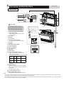
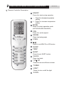
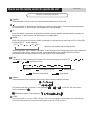
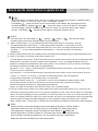
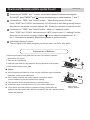
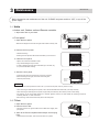
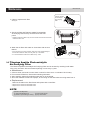
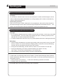
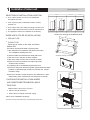
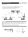
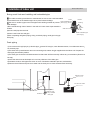
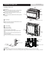
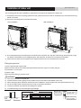
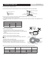
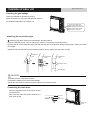
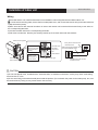
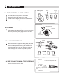
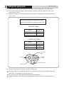
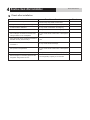
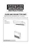
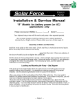
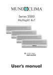
MULTISPLIT CONSOLE H3M
Installation & user's manual
MUCNR-H3M
www.mundoclima.com
CL20827 to CL20829
English
Contents
CONTENTS
1. User' s manual ......................................................................................................................................... 3
2. Installation manual ................................................................................................................................. 17
Thank you for selecting our products
One of the benefits awaiting you with our room air conditioner is not only
comfort of life but also good health. This operation instruction brings you the
many omfort and technological features your unit has to offer. In addition, it
provides you vital information about maintenance, service and economical
operating. Take the next few minutes to discover how to get your comfort and
economy of the operation from your new room air conditioner.
The figures in this manual may be different with the material objects, please
refer to the material objects for reference.
This appliance is not intended for use by persons (including children) with
reduced physical , sensory or mental capabilities or lack of experience
and knowledge,unless they have been given supervision or instruction
concerning use of the appliance by a person responsible for their safety.
Children should be supervised to ensure that they do not play with the appliance.
External static pressures at the appliance was tested is 0 Pa
Fuse link: T250 V; 3.15 A
Contents
USER' S MANUAL
1. Part names and their functions ............................................................................................................... 4
2. How to use the remote control to operate the unit ................................................................................. 5
3. Maintenance ........................................................................................................................................ 10
4. Operating guide ................................................................................................................................... 13
5. Usage tips ............................................................................................................................................ 14
6. Precautions .......................................................................................................................................... 15
7. Checking before contact the service man ............................................................................................ 16
1
Part names and their functions
USER' S MANUAL
INDOOR UNIT
1
2
6
3
3
8
9
11
10
12
13
14
7
4
15
2
CAUTION
Before opening the front panel, be sure to
stop the operation and turn the breaker OFF.
Do not touch the metal parts on the inside
of the indoor unit, as it may result in injury.
1. Titanium Apatite Photocatalytic
Air-Purifying Filter:
• These filters are attached to the inside
of the air filters.
2. Air outlet
3. Display
4. Front panel
5. Louvers (vertical blades)
5
Air outlet selection switch
•
This setting blows air from
upper outlet only.
•
This setting automatically
decides a blow pattern
depending on mode and
conditions.
16
• This setting is recommended.
17
• The unit is shipped from the
factory with this setting.
• The louvers are inside of the air outlet.
6. Air inlet
7. Air filter
8. Flap (horizontal blade)
9. Cool mode lamp
10. Heat mode lamp
11. Dry mode lamp
12. Run lamp
13. LED display
14. Indoor Unit ON/OFF switch:
Opening the Front Panel
Indoor unit
wiring terminal
N(1) 2
BU
BK
3
BN
YELLOW/
GREEN
• Push this switch once to start operation.
Push once again to stop it.
• The operation mode refers to the following table.
Model
Mode
COOLING COOL
ONLY
Temperature Air flow rate
setting
25℃
AUTO
HEAT
25℃
AUTO
AUTO
PUMP
• This switch is useful when the remote controller
is missing.
15.Signal receiver:
• It receives signals from the remote controller.
• When the unit receives a signal, you will hear
a short beep.
•Settings changed.....beep
16.Air outlet selection switch
17.Room temperature sensor:
•It senses the air temperature around the unit.
NOTE:
① If the supply cord is damaged, it must be replaced by the manufacturer or its service agent or a similarly qualified person in order to avoid a hazard.
② The appliance shall be installed in accordance with national wiring regulations.
③ An all-pole disconnection switch having a contact separation of at least 3mm in all polesshould be connected in fixed wiring. For models with a power
plug, make sure the plugis within reach after installation.
2
How to use the remote control to operate the unit
USER' S MANUAL
Remote Controller Description
1
ON/OFF
Press it to start or stop operation.
2
- : Press it to decrease temperature
setting.
3
+ : Press it to increase temperature
setting.
4
MODE
Press it to select operation mode
(AUTO/COOL/DRY/FAN/HEAT).
5
FAN
Press it to set fan speed.
1
6
SWING
Press it set swing angle.
3
2
7
8
I FEEL
/
Press it to set HEALTH or AIR function.
4
5
9
SLEEP
6
7
10
TEMP
8
9
11
QUIET
10
11
12
13
14
16
15
Press it to set QUIET function.
12
CLOCK
Press it set clock.
13
T-ON T-OFF
Press it to set auto-off /auto-on timer.
14
TURBO
15
LIGHT
Press it to turn on/off the light.
16
X-FAN
How to use the remote control to operate the unit
USER' S MANUAL
Remote Controller Description
1 ON/OFF :
Press this button to turn on the unit .Press this button again to turn off the unit.
2
Press this button to decrease set temperature. Holding it down above 2 seconds rapidly decreases
set temperature. In AUTO mode, set temperature is not adjustable.
3
+:
Press this button to increase set temperature.Holding it down above 2 seconds rapidly increases set
temperature. In AUTO mode, set temperature is not adjustable.
4 MODE :
Each time you press this button,a mode is selected in a sequence that goes from AUTO, COOL,DRY,
FAN,and HEAT *, as the following:
AUTO
COOL
DRY
FAN
HEAT
*
*Note:Only for models with heating function.
After energization, AUTO mode is defaulted. In AUTO mode, the set temperature will not be displayed
on the LED of the indoor, and the unit will automatically select the suitable operation mode in
accordance with the room temperature to make indoor room comfortable.
5 FAN :
This button is used for setting Fan Speed in the sequence that goes from AUTO,
, then back to Auto.
to
,
,
,
Auto
Low speed
Low-Medium speed
Medium speed
Medium-High speed
6
High speed
SWING:
Press this button to set up &down swing angle, which circularly changes as below:
OFF
This remote controller is universal . If any command
out the command as
,
or
is sent out, the unit will carry
indicates the guide louver swings as:
7 I FEEL:
Press this button to turn on I FEEL function. The unit automatically adjust temperature according to
the sensed temperature. Press this button again to cancel I FEEL function.
How to use the remote control to operate the unit
8
9
●
●
●
●
●
USER' S MANUAL
/
Press this button to achieve the on and off of healthy and scavenging functions in operation status.
Press this button for the first time to start scavenging function;
LCD displays“ ”. Press the button for the second time to start healthy and scavenging functions
simultaneously; LCD displays“ ” and “ ” . Press this button for the third time to quit healthy
and scavenging functions simultaneously. Press the button for the fourth time to start healthy
function; LCD display “
” . Press this button again to repeat the operation above.
SLEEP:
), Sleep 2 (
),Sleep 3 (
) and cancel the Sleep,
Press this button, can select Sleep 1 (
circulate between these, after electrified, Sleep Cancel is defaulted.
Sleep 1 is Sleep mode 1, in Cool, Dehumidify modes: sleep status after run for one hour, the main
unit setting temperature will increase 1 ℃,setting temperature increased 2℃, the unit will run at this
setting temperature; In Heat mode: sleep status after run for one hour, the setting temperature will
decrease 1 ℃, 2 hours, setting temperature will decrease 2 ℃, then the unit will run at this setting
temperature.
Sleep 2 is sleep mode 2, that is air conditioner will run according to the presetting a group of sleep temperature curve.
Sleep 3- the sleep curve setting under Sleep mode by DIY:
(1) Under Sleep 3 mode, press "Turbo" button for a long time, remote control enters into user individuation sleep
setting status, at this time, the time of remote control will display "1 hour ", the setting temperature "88" will
display the corresponding temperature of last setting sleep curve and blink (The first entering will display
according to the initial curve setting value of original factory);
(2) Adjust "+" and "-" button, could change the corresponding setting temperature, after adjusted, press
"Trubo "button for confirmation;
(3) At this time, 1 hour will be automatically increased at the timer postion on the remote control, (that are
"2 hours " or "3 hours " or "8 hours "), the place of setting temperature "88" will display the
corresponding temperature of last setting sleep curve and blink;
(4) Repeat the above step (2) ~ (3) operation, until 8 hours temperature setting finished, sleep
curve setting finished, at this time, the remote control will resume the original timer display;
temperature display will resume to original setting temperature.
Sleep3- the sleep curve setting under SLEEP mode by DIY could be inquired:
The user could accord to sleep curve setting method to inquire the presetting sleep curve, enter into user
individuation sleep setting status, but do not change the temperature, press "Turbo" button directly for confirmation.
Note: In the above presetting or enquiry procedure, if continuously within10s, there is no button pressed, the
sleep curve setting within10s, there is no button pressed, the sleep curve setting status will be automatically
quit and resume to display the original displaying. In the presetting or enquiry procedure, press "ON/OFF"
button, "Mode" button, "Timer"button or "Sleep" button, the sleep curve setting or enquiry status will quit similarly.
10 TEMP:
Press this button, could select displaying the indoor setting temperature or indoor ambient
temperature.When the indoor unit firstly power on it will display the setting temperature,
if the temperature's displaying status is changed from other status to" ",displays the
ambient temperature, 5s later or within 5s, it receives other remote control signal that will
return to display the setting temperature. if the users haven't set up the temperature
displaying status,that will display the setting temperature.
How to use the remote control to operate the unit
USER' S MANUAL
11 QUIET:
Press this button, the Quiet status is under the Auto Quiet mode (display " " and "Auto" signal)
and Quiet mode (display "
" singal) and Quiet OFF (there is no signal of "
" displayed),
after powered on, the Quiet OFF is defaulted. Note: the Quiet function cannot be set up in Fan
and Dry mode;Under the Quiet mode (Display "
" signal), the fan speed is not available.
12 CLOCK :
Press CLOCK button, blinking
. Within 5 seconds,pressing + or - button adjusts the present time.
Holding down either button above 2 seconds increases or decreases the time by 1 minute every 0.5
second and then by 10 minutes every 0.5 second. During blinking after setting, press CLOCK button
again to confirm the setting,and then
will be constantly displayed.
13 T-ON / T-OFF:
Press T-ON button to initiate the auto-ON timer. To cancel the auto-timer program, simply press this
button again.
After press of this button,
disappears and "ON "blinks .00:00 is displayed for ON time setting.Within
5 seconds,press + or - butt on to adjust the time value.Every press of either button changes the time
setting by 1minute. Holding down either button rapidly changes the time setting by 1 minute and then
10 minutes.Within 5 Seconds after setting,press TIMER ON button to confirm.
Press T-OFF button to initiate the auto-off timer. To cancel the auto-timer program, simply press the
button again.TIMER OFF setting is the same as TIMER ON.
14 TURBO:
Press this button to activate / deactivate the Turbo function which enables the unit to reach the preset
temperature in the shortest time. In COOL mode, the unit will blow strong cooling air at super high fan
speed. In HEAT mode, the unit will blow strong heating air at super high fan speed.
15 LIGHT:
Press LIGHT button to turn on the display's light and press this button again to turn off the display 's
light. If the light is turned on ,
is displayed. If the light is turned off,
disappears.
16 X-FAN:
Pressing X-FAN button in COOL or DRY mode,the icon
is displayed and the indoor fan will continue
operation for 10 minutes in order to dry the indoor unit even though you have turned off the unit.
After energization, X-FAN OFF is defaulted. X-FAN is not available in AUTO,FAN or HEAT mode.
17 Combination of "+" and "-" buttons: About lock
Press " + " and "-" buttons simultaneously to lock or unlock the keypad. If the remote controller is
locked,
is displayed. In this case, pressing any button, blinks three times.
How to use the remote control to operate the unit
USER' S MANUAL
18 Combination of "MODE " and "-" buttons : About switch between Fahrenheit and centigrade
At unit OFF, press " MODE " and " -" buttons simultaneously to switch between ℃ and ℉ .
19 Combination of " TEMP " and "CLOCK" buttons : About Energy-saving Function
Press "TEMP" and "CLOCK" simultaneously in COOL mode to start energy-saving function.
Nixie tube on the remote controller displays "SE". Repeat the operation to quit the function.
20 Combination of " TEMP " and "CLOCK" buttons : About 8℃ Heating Function
Press "TEMP" and "CLOCK" simultaneously in HEAT mode to start 8℃ Heating Function
Nixie tube on the remote controller displays " " and a selected temperature of " 8℃" .
(46℉ if Fahrenheit is adopted). Repeat the operation to quit the function.
21 About Back-lighting Function
The unit lights for 4s when energizing for the first time, and 3s for later press.
Replacement of Batteries
1.Remove the battery cover plate from the rear of the remote controller.
(As shown in the figure)
2.Take out the old batteries.
3.Insert two new AAA1.5V dry batteries, and pay attention to the polarity.
4. Reinstall the battery cover plate.
★ Notes:
● When replacing the batteries, do not use old or different types of batteries,
otherwise, it may cause malfunction.
●
●
●
●
If the remote controller will not be used for a long time, please
remove batteries to prevent batteries from leaking.
The operation should be performed in its receiving range.
It should be kept 1m away from the TV set or stereo sound sets.
If the remote controller does not operate normally, please take the
batteries out and reinsert them after 30 seconds.If it still can't operate properly,
replace the batteries.
Sketch map for
replacing batteries
3
Maintenance
USER' S MANUAL
Before inspection and maintenance of the unit. PLEASE set power switch to “OFF” to cut off the
power supply.
3.1 Units
● Indoor unit, Outdoor unit and Remote controller
1. Wipe them with dry soft cloth.
● Front panel
1. Open the front panel.
Slide the two stoppers on the left and right sides inward until they click.
2. Remove the front panel.
• Remove the string.
• Allowing the front panel to fall forward will enable you to remove it.
String
3. Clean the front panel.
• Wipe it with a soft cloth soaked in water.
• Only neutral detergent may be used.
• In case of washing the front panel with water,dry it with cloth, dry
it up in the shade after washing.
4. Attach the front panel.
String
• Insert the front panel into the grooves of the unit (3 places).
• Attach the string to the right, inner-side of the front grille.
• Close the panel slowly.
Place front
panel in
grooves.
CAUTION
• Don’t touch the metal parts of the indoor unit. If you touch those parts, this may cause an injury.
• When removing or attaching the front panel, use a robust and stable stool and watch your steps carefully.
• When removing or attaching the front panel, support the panel securely with hand to prevent it from falling.
• For cleaning, do not use hot water above 40°C, benzine, gasoline, thinner, nor other volatile oils, polishing compound,
scrubbing brushes, nor other hand stuff.
• After cleaning, make sure that the front panel is securely fixed.
3.2 Filters
1. Open the front panel.
2. Remove the air filter.
• Press the claws on the right and left of the air filter down slightly, then
pull upward.
3. Take off the Titanium Apatite Photocatalytic Air-Purifying
Filter.
• Hold the tabs of the frame, and remove the claws in 4 places.
Maintenance
USER' S MANUAL
Titanium Apatite
Photocatalytic
Air-Purifying
Filter
4. Clean or replace each filter.
See figure.
5. Set the air filter and Titanium Apatite Photocatalytic
Air-Purifying Filter as they were and close the front
panel.
• Operation without air filters may result in troubles as dust will accumulate
inside the indoor unit.
6. Wash the air filters with water or clean them with vacuum
cleaner.
• If the dust does not come off easily, wash them with neutral detergent
thinned with lukewarm water, then dry them up in the shade.
• It is recommended to clean the air filters every week.
3.3 Titanium Apatite Photocatalytic
Air-Purifying Filter
The Titanium Apatite Photocatalytic Air-Purifying Filter can be renewed by washing it with water
once every 6 months. We recommend replacing it once every 3 years.
● Maintenance
1. Vacuum dusts, and soak in warm water or water for about 10 to 15 minutes if dirt is heavy.
2. Do not remove filter from frame when washing with water.
3. After washing, shake off remaining water and dry in the shade.
4. Since the material is made out of paper, do not wring out the filter when removing water from it.
● Replacement
Remove the tabs on the filter frame and replace with a new filter.
• Dispose of the old filter as flammable waste.
• Dispose of the old filter as flammable waste.
NOTE
• Operation with dirty filters:
(1) cannot deodorize the air.
(3) results in poor heating or cooling.
(2) cannot clean the air.
(4) may cause odour.
Air filter
Maintenance
USER' S MANUAL
Check
Check that the base, stand and other fittings of the outdoor unit are not decayed or corroded.
Check that nothing blocks the air inlets and the outlets of the indoor unit and the outdoor unit.
Check that the drain comes smoothly out of the drain hose during COOL or DRY operation.
• If no drain water is seen, water may be leaking from the indoor unit. Stop operation and consult
the service shop if this is the case.
3. 4 Before a long idle period
1. Operate the “FAN only” for several hours on a fine day to dry out the inside.
• Press “MODE” button and select “FAN” operation.
• Press “ON/OFF” button and start operation.
2. After operation stops, turn off the breaker for the room air conditioner.
3. Clean the air filters and set them again.
4. Take out batteries from the remote controller.
NOTE
• When a multi outdoor unit is connected, make sure the heating operation is not used at the other room befure you use the fan
operation.
Working temperature range
Indoor sideDB/WB(oC)
Outdoor sideDB/WB(oC)
Maximum cooling
32/23
48/-
Maximum heating
27/---
27/-
The operating temperature range (outdoor temperature) for cooling unit is -15℃~48℃;
for cooling and heating unit is -15℃~48℃.
4
Operating guide
USER' S MANUAL
Working principle and special functions for cooling
Principle:
Air conditioner absorbs heat in the room and transmit to outdoor and discharged, so that
indoor ambient temperature decreased, its cooling capacity will increase or decrease by
outdoor ambient temperature.
Anti-freezing function:
If the unit is running in COOL mode and in low temperature, there will be frost formed on
the heat exchanger, when indoor heat exchanger temperature decreased below 0℃ , the
indoor unit microcomputer will stop compressor running and protect the unit.
Working principle and special functions for heating
Principle:
* Air conditioner absorbs heat from outdoor and transmits to indoor, in this way to increase
room temperature. This is the heat pump heating principle, its heating capacity will be
reduced due to outdoor temperature decrease.
* If outdoor temperature becomes very low, please operate with other heating equipments.
Defrosting:
* When outdoor temperature is low but high humidity, after a long while running, frost will
form on outdoor unit, that will effect the heating effect, at this time, the auto defrosting
function will act, the heat running will stop for 8-10mins.
* During the auto defrosting, the fan motors of indoor unit and outdoor unit will stop.
* During the defrosting, the indoor indicator flashes, the outdoor unit may
emit vapor, This is due to the defrosting, it isn't malfunction.
* After defrosting finished,the heating will recover automatically.
Anti-cool wind function:
In Heat mode, the following three kinds of status, if indoor heat exchanger hasn't achieve
certain temperature that indoor fan motor will not start, in this way to prevent blowing cool
wind (within 3mins):
1. Heat operation just startedup. 2. After Auto defrosting operation is finished.
3. Heating under low temperature.
The climate type of this unit is according to the nameplate.
5
U sage tips
The temperature should not be set lower than
what you need. This would result to increase
energy cost.
Clean the air filter every week for higher
efficiency.
Draw close curtains or close glass windows
when cooling to prevent heat load from sun
light which may cause more electricity cost.
USER' S MANUAL
To distribute cool air through out the roon,
adjust air flow direction as shown by the
arrows (see picture) to diffuse cool air.
Close window and door while operating the unit
to prevent leakage of cooled air to save energy.
In case of ineffective ventilation,open the
window to ventilate the room air once in a
while but not too long since cooled air will be
uselessly drained out.
6
Precautions
USER' S MANUAL
Check electrical system(voltage and frequency).
Use the proper power supply indicated on the
unit to operate the airconditioner and only fuses
with specified capacity.Do not use pieces of wire
instead of fuse.
Turn off the airconditioner if ,while running,
electricity interference occurs.If the unit is not
to be used for a long time,cut off the power
supply main switch.
Do not insert objects into the air inlet or outlet
when the airconditioner is running as it may
cause damage or personal injury .Also pay
special attention when children are around.
Do not locate any obstacle against the air
flow direction of indoor and outdoor unit.
Inefficient performance or malfunction may result.
Do not channel the air flow directly at people,
especially infants,aged persons or patients.
Do not locate a heater or any other heat source
close to the unit.The heat may deform plastic
parts.
7
Checking before contact the service man
USER' S MANUAL
Check the following before contact the service man.You may find the solution to your problems.
After checking,if it still does not operate, please contact your local dealer.
PROBLEM
NO operation
CAUSES
Check if eletrical wire is damaged & check if breaker
switch is still on.
Check if the power supply is in order.
Check if the timer switch is on or not.
Check if the preset temperature is too high.
The air conditioner runs
but does not cool enough.
Check if the sunlight shines directly into the room.
Check if the door and window are opened.
Check if there is anything obstructing the air discharge
Check if the exhaust fan still operates
Check if the air filter is dirty or clogged.
Vapor or mist fume coming
out of the unit while runing.
Inoperative
remote control.
Hot air in the room mixes with cool air.This causes smoke fume.
Loosened or disconnected wire between the unit and the
display.
Check if the batteries are inserted in correct directions.
Check if the batteries are exhaused or not.
Contents
INSTALLATION MANUAL
1. Installation of indoor unit ...................................................................................................................... 18
2. Pipe preparation................................................................................................................................... 26
3. Refrigerant piping work ........................................................................................................................ 27
4. Routine check after installation ............................................................................................................ 28
1
Installation of indoor unit
INSTALLATION MANUAL
SELECTION OF INSTALLATION LOCATION.
Half conceated
Exposed
● Such a place where cool air can be distributed
Concealed
Mounting plate
throughout the room.
●
Such a place where condensation water is easily
drained out.
● Such a place that can handle the weight of indoor unit.
Molding
● Such a place which has easy access for maintenance.
● The appliance shall not be installed in the laundry.
Grid(field supply)
Floor lnstallation
Wall Installation
Location for securing the installation panel.
THERE ARE 2 STYLES OF INSTALLATION.
●
700
CEILING TYPE
200
120
FLOOR TYPE
Each type is similar to the other as follows;
644
220
Indoor unit
120
570
600
●
0
30
16
1) the restrictions on installation specified in the indoor
unit installation drawings are met.
2) both air intake and exhaust have clear paths met.
3) the unit is not in the path of direct sunlight.
4) the unit is away from the source of heat or steam.
5) there is no source of machine oil vapour (this may
shorten indoor unit life).
6) cool(warm) air is circulated throughout the room.
7) the unit is away from electronic ignition type fluorwscent lamps
17
0
220
The indoor unit should be sited in a place where:
Schematic drawing of hooks:
30
200
mm
(inverter or rapid stert type) as they may shorten the remote
controller range.
8) the unit is at least 1 metre away from any television or radio
set(unit may cause interference with the picture or sound).
INSTALLATION
PAPER PLANK
CAUTIONS FOR INSTALLATION WHERE
AIR CONDITIONER TROUBLEIS LIABLE
TOOCCUR.
● Where there is too much of oil area.
● Where it is acid base area.
●
150cm
or more
Where there is irregular electrical supply.
Indoor Unit Installatio n Drawings
150cm
or more
The indoor unit may be mounted in any of the three styles shown here.
150cm
or more
150cm
or more
15cm or below
from the floor
Installation of indoor unit
INSTALLATION MANUAL
Refrigerant piping
1)Drill a hole ( 55mm in diameter ) in the spot indicated by the symbol in the illustration as below .
2)The location of the hole is different depending on which side of the pipe is taken out .
3)For piping ,see Connecting the refrigerant pipe ,under Indoor Unit Installation(1).
4)Allow space around the pipe for a easier indoor unit pipe connection.
(Unit : mm)
60
45
Wall
Left bottom piping
75
Right bottom piping
75
45
Right back piping
Left/right piping
45
75
45
75
45
Left back piping
CAUTION
Min.allowable length
The suggested shortest pipe length is 2.5m,in order to avoid noise from the outdoor unit and vibration.
(Mechanical noise and vibration may occur depending on how the unit is installed and the environment in which it is
used.)
See the installation manual for the outdoor unit for the maximum pipe length.
For multi-connections ,see the installation manual for the multi-outdoor unit.
350
wall
45
Refrigerant pipe
75
Floor
Installation of indoor unit
INSTALLATION MANUAL
Boring a wal l hole and installing wal l embedded pipe
For walls containing metal frame or metal board ,be sure to use a wall embedded
pipe and wall cover in the feed-through hole to prevent water leakage.
Be sure to caulk the gaps around the pipes with caulking material to prevent
water leakage.
1)Bore a feed-through hole of 55mm in the wall so it has a down slope toward the
outside.
2)Insert a wall pipe into the hole.
3)Insert a wall cover into wall pipe .
4)After completing refrigerant piping, wiring, and drain piping, caulk pipe hole gap
Inside
Wall embedded pipe
(field supply)
Wall hole cover
Outside
Caulking
Φ55
Wall embedded pipe
(field supply)
with putty.
Drain piping
1)Use commercial regid polyvinyl chloride pipe general VP 20 pipe, outer diameter 26mm, inner diameter 20mm
for the drain pipe.
2)The drain hose (outer diameter 18mm at connecting end, 220mm long)is supplied with the indoor unit. Prepare the
drain pipe picture below position.
3)The drain pipe should be inclined downward so that water will flow smoothly without any accumulation.(Should not
be trap.)
4)Insert the drain hose to this depth so it won’t be pulled out of the drain pipe.
5)Insulate the indoor drain pipe with 10mm or more of insulation material to prevent condensation.
6)Remove the air filters and pour some water into the drain pan to check the water flows smoothly.
150
Must be no trap
100
Do not touch water
100
Drain hose
Reducer
50mm
or more
Vinyl chloride
drain pipe
Installation of indoor unit
INSTALLATION MANUAL
Installing indoor unit
3 tabs
1.Preparation
Casing
Open the front panel, remove the 4 screws and dismount the front grille while pulling it forward.
Front
grille
Follow the arrows to disengage the clasps on the
front case to remove it.
Follow the procedure below when removing the slit
Front panel
Remove
front grille
portions.
For Moldings
Remove 4 screws
Open the front panel
Remove the pillars. (Remove the slit portions on the
bottom frame using nippers.)
2)Upper casing
For Side Piping
Remove the pillars.
1)Remove the 7screws.
2)Remove the upper casing (2 tabs).
3)Remove the left and right casings (2 tabs on each
side ).
4)Remove the slit portions on the bottom frame and
casings using nippers .
5)Return by following the steps in reverse order(3>2>
1).
3)Side
casings
3)Side
casings
Remove 7 screws
Casing
Remove the pillar
Bottom frame
Casing
Remove the pillar
Remove the pillar
2.Installation
Secure using 6 screws for floor installations.(Do not forget to secure to the rear wall.)
For wall installations, secure the mounting plate using 5 screws and the indoor unit using 4 screws.
Installation of indoor unit
INSTALLATION MANUAL
The mounting plate should be installed on a wall which can support the weight of the indoor unit.
1) Temporarily secure the mounting plate to the wall, make sure that the panel is completely level, and mark the boring
points on the wall.
2) Secure the mounting plate to the wall with screws.
Floor Installation
Wall Installation
Casing
200m
m
Molding
6screws
6screws
3) Once refrigerant piping and drain piping connections are complete, fill in the gap of the through hole with putty. A gap
can lead to condensation on the refrigerant pipe, and drain pipe, and the entry of insects into the pipes.
4) Attach the front panel and front grille in their original positions once all connections are complete.
Flaring the pipe end
1)Cut the pipe end with a pipe cutter.
2)Remove burrs with the cut surface facing downward so that the chips do not enter the pipe.
3)Fit the flare nut on the pipe.
4)Flare the pipe.
5)Check that the flaring is properly made.
WARNING
1)
2)
3)
4)
5)
DO not use mineral oil on flared part.
Prevent mineral oil from getting into the system as this would reduce the lifetime of the units.
Never use piping which had been used for previous installations. Only use parts which are delivered with the unit.
Do never install a drier to this R410A unit in order to guarantee its lifetime.
The drying material may dissolve and damage the system.
6) Incomplete flaring may cause refrigerant gas leakage.
Flaring
Set exactly at the position shown below
Flare tool for R410A
A
Cut exactly
at right
angles
Die
Renove
burrs
A
Conventional flare tool
Clutch-type
Clutch-type
(Rigid-type)
Wing-nut type
(lmperial-type)
0-0.5mm
1.0-1.5mm
1.5-2.0mm
Flare’s inner
surface must
be scratch-free
The pipe end must
be evenly flared in
a perfect circle
Make sure that the
flare nut is fitted
Installation of indoor unit
INSTALLATION MANUAL
Connecting the refrigerant pipe
1) Use torque wrenches when tightening the flare nuts to prevent damage to the flare nuts and gas leaks.
Open-end wrench (fixed)
Coat here with refrigeration oil
Flare nut
Wrench
Connection pipe
Indoor unit tubing
2) Align the centres of both flares and tighten the flares and tighten the flare nuts 3 or 4 turns by hand.
Then tighten them fully with the torque wrenches.
3) To prevent gas leakage, apply refrigeration oil on both inner and outer surfaces in the flare. (Use refrigeration oil for
R410A.)
Flare nut tightening torque
Gas side
09K/12K
Liquid side
18K
3/8 inch
31-35 N.m
09K/12K/18K
1/2 inch
1/4 inch
50-55 N.m
15-20 N.m
Be sure to
place a cap.
Caution on piping handling
1)Protect the open end of the pipe against dust and moisture.
2)All pipe bends should be as gentle as possible. Use a pipe bender for
bending.
If no flare cap is
available,cover
the flare mouth
with tape to keep
dirt or water out.
(Bending radius should be 30 to 40mm or larger.)
Inter-unit wiring
Selection of copper and heat insulation materials
When using commercial copper pipes and fittings, observe the
following:
1)Insulation material: Polyethylene foam
Heat transfer rate:0.041 to 0.052W/mK(0.035 to 0.045kca/(mh
Refrigerant gas pipe’s surface temperature reaches 110 max.
Choose heat insulation materials that will withstand this temperature.
Gas pipe
Liquid pipe
Liquid pipe
insulation
Gas pipe
insulstion
Finising tape
2)Be sure to insulate both the gas and liquid piping and to provide insulation dimensions as below.
Gas side
09K/12K
O.D. 9.5mm
Liquid side
18K
O.D. 12.7mm
Thickness 0.8mm
Gas pipe thermal insulation
09K/12K
O.D. 6.4mm
I.D. 12-15mm
Liquid pipe
thermal insulation
18K
I.D. 14-16mm
Thickness 10mm Min.
3)Use separate thermal insulation pipes for gas and liquid refrigerant pipes.
I.D. 8-10mm
Installation of indoor unit
INSTALLATION MANUAL
Checking for gas leakage
1)Check for leakage of gas after air purging
2)See the sections on air purges and gas leak checks in
the installation manual for the outdoor unit.
Check for leakage here
Apply soapy water and check carefully for leaking gas.
wipe soapy water off after
the check is complete.
Attaching the connection pipe
Attach the pipe after checking for gas leakage, described above.
1)Cut the insulated portion of the on-site piping, matching it up with the connecting portion.
2)Secure the slit on the refrigerant piping side with the butt joint on the auxiliary piping using the tape, making sure there
are no gaps.
3)Wrap the slit and butt joint with the included insulation sheet, making sure there are no gaps.
Refrigerant
pipe
Slit
Refrigerant
pipe
Refrigerant
pipe
Slit
Insulation sheet
Tape
Auxiliary pipe
CAUTION
1)Insulate the joint of the pipes securely.
Incomplete insulation may lead to water leakage.
2)Push the pipe inside so it does not place undue force on the front grille.
Connecting the drain hose
Insert the supplied C drain hose into the socket
of the drain pan.
Fully insert the drain hose until it adheres to a
seat of the socket.
Drain pan
Seal
Drain hose
Drain pan
Seal
Installation of indoor unit
INSTALLATION MANUAL
Wiring
With a Multi indoor unit, install as described in the installation manual supplied with the Multi outdoor unit.
Live the sensor securing plate, remove the front metal plate cover, and connect the branch wiring to the terminal block.
1)Strip wire ends (15mm)
2)Mach wire colours with terminal numbers on indoor and outdoor unit’s terminal blocks and firmly screw wires to
the corresponding terminals.
3)Connect the earth wires to the corresponding terminals.
4)Pull wires to make sure that they are securely latches up, then retain wires with wire retainer.
Sensor securing plate
Front metal
plate cover
Firmly secure wire
retainer so that
wires sustain no
external stress.
N(1)
2
3
Terminal block
Electrical
component
box
Wire retainer
Use the specified wire type.
Indoor unit
Shape wires so
that the front metal
plate cover will fit
securely.
Firmly fix the wires with the
terminal screws
Outdoor unit
When wire length exceeds 10m,
use 2.0mmdiameter wires
Firmly fix the wires with the
terminal screws
CAUTION
1)Do not use tapped wires, stranded wires, extensioncords, or starburst connections, as they may cause overheating,
electrical shock, or fire.
2)Do not use locally purchased electrical parts inside the product. (Do not branch the power for the drain pump, etc, from
the terminal block.) Doing so may cause electric shock or fire.)
2
Pipe preparation
INSTALLATION MANUAL
Cutting Tool
Wrong
Right
2.1 PIPE & ELECTRICAL WIRE CUTTING
Sloped Cut Rough Cut
Use cutting tools easily found in the market.
Measure precisely both outer & inner pipe.
Provide a little bit longer pipe than the measurement.
Wire must be 1.5 m. longer than the refrigerant tube.
Refrigerant Tube
2.2 REAMING
Reamer
Clean inside of the inner refrigerant tube.
While reaming, the tube end must be on the top of the
reamer to prevent any dust going back into the tube.
Up side
down position
0.5 mm.
2.3 FLARING THE PIPE END
Flare both ends of the pipe with flaring kit by fitting the
flare nut on the pipe before flaring.Set the die on the
pipe so that pipe end is 0.5 mm. above top of the die.
Check if the pipe end is even and pertectly round.
Refrigerant Tube
Uneven
Slope
2.4 WIRE CONNECTION AND TAPE COVERING
Flare Kit
Poor skin
30-40 mm
Cracked
Uneven
Thickness
Low Pressure Refrigerant Tube
(see the picture on the right side)
Connecting
Wire
High Prseeure
To indoor Unit
Refrigerant Tube
To Outdoor Unit
3
3. 1
Refrigerant piping work
INSTALLATION MANUAL
Select copper pipes for gas and liquid as informed in specific table(see the pipe table below)
3.2 For dust and moisture protection, before assembly of the pipe and its insulation,both end of the
pipe must be covered.
3.3 Avoid pipe bending as much as possible.If it is necessary, the bending radius must be more than
3cm. or 4cm.
Gas pipe and liquid pipe insulation depends upon
copper pipe size and the insulation thickness = 3/8"
GAS PIPE TABLE
MODEL
PIPE SIZE
9K
12K
3/8"
18K
3/8"
1/2"
LIQUID PIPE TABLE
MODEL
PIPE SIZE
9K
12K
1/4"
18K
1/4"
1/4"
Connecting
Wire
Liquid
Pipe
Gas Pipe
Dia. Drain Pipe 1/2"
Piping Tape
3.4 The connection between an indoor unit and an outdoor unit.
Unscrew the flare nut for releasing pressure gas in the indoor unit.If there is no high pressure gas
blowing out, it is the signal of a leaking indoor unit.
Fit the flare nut to the liquid pipe.Flare the pipe's end with flare tool.
Tighten both flare nuts into gas pipe and liquid pipe at the indoor unit with two holding spanners.
4 Routine check after installation
INSTALLATION MANUAL
Check after installation
Items to be checked
Possible malfunction
Has it been fixed firmly?
The unit may drop,shake or emit noise.
Have you done the refrigerant leakage test?
It may cause insufficient refrigerating capacity.
Is heat insulation sufficient?
It may cause condensation and dripping.
Does the unit drain well?
It may cause condensation and dripping.
Is the voltage in accordance with the rated
voltage marked on the nameplate?
It may cause electric malfunction or damage the
part.
Is the electrical wiring and piping connection
installed correctly and securely?
It may cause electric malfunction or damage the
part.
Has the unit been connected to a secure earth
connection?
It may cause electrical leakage.
Is the power cord specified?
It may cause electric malfunction or damage the
part.
Has the inlet and outlet been covered?
It may cause insufficient refrigerating capacity.
Has the length of connection pipes and the
refrigerant charge been record?
The refrigerating capacity is not accurate
Situation
Notes:
ASK FOR MORE INFORMATION
Phone: (+34) 93 446 27 80
eMail: [email protected]
TECHNICAL ASSISTANCE
Phone: (+34) 93 652 53 57
www.mundoclima.com