1
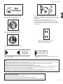
4"#
4"#$8
4"#
/WNERSMANUAL
-ANUALDELPROPIETARIO
970-47189-200 2009.05
TBC-550/TBC-600
4"#
4"#$8
4"#
Read the manual carefully before
operating this machine.
Owner's manual
GB-1
TBC-550/TBC-600
Meanings of symbols or labels. (NOTE! Some units do not carry them)
WARNING
The engine exhaust from this product contains
chemicals known to the State of California to cause
cancer, birth defects and other reproductive harm.
Do not use metal/rigid blades when this sign is
shown on the unit.
Read, understand and follow all warnings and
instructions in this manual and on the unit.
15m
50FT
15m
50FT
Keep all children, bystanders and helpers 15m
away from the unit. If anyone approaches you,
stop the engine and cutting attachment
imme-diately.
It is important that you read, fully understand and observe
the following safety precautions and warnings. Careless
or improper use of the unit may cause serious or fatal
injury.
Be careful of thrown objects.
Always wear eye, head and ear protectors
when using this unit.
GB-2
TBC-550/TBC-600
Max
9,900rpm
Blade thrust may occur when the spinning
blade contacts a solid object in the critical area.
A dangerous reaction may occur causing the
entire unit and operator to be thrust violently.
This reaction is called BLADE THRUST. As a
result, the operator may lose control of the unit
which may cause serious or fatal injury. Blade
thrust is more likely to occur in areas where it is
difficult to see the material to be cut.
Shows maximum shaft speed. Do not use the
cutting attachment whose max rpm is below
the shaft rpm.
Gloves should be worn when necessary, e. g.,
when assembling cutting equipment.
Explains choke position. Upper sign indicates
choke closed and the lower fully open.
Use anti-slip and sturdy footwear.
P L A CE GUA RD
B RA CK ET
B E TW E E N
A RROW S
Indicates blade guard location for a trimmer head or Brain head.
Do not attach
handle above
this point
Indicates handle location. Do not attach handle above this point.
WARNING!
Read the Operator's Manual and follow all warnings and safety instructions. Failure to do so can result in serious injury to the operator
and /or bystanders.
Objects may be thrown or ricochet in all directions. ALWAYS WEAR EYE PROTECTION.
Keep bystanders at least 50 feet (15m) away.
To reduce the chance of hearing loss, always wear ear protection.
To reduce the risk of injury from loss of control, never use a metal blade on a curved shaft grass trimmer. Never use a metal blade on any
brushcutter without barrier bar or bicycle handle configuration and safety strap
Use of a blade may cause a sudden sideways, forward or backward motion of the brushcutter when the blade contacts a solid object. See
Owner's manual for model specific details.
Before using your machine
Read the manual carefully.
Check that the cutting equipment is correctly assembled and adjusted.
Start the unit and check the carburetor adjustment. See "Maintenance".
GB-3
TBC-550/TBC-600
Index
What is what?
Warnings and safety instructions
Assembly procedures
Operating procedures
Maintenance
Specifications
GB-4
5
6
7
9
12
14
TBC-550/TBC-600
1. What is what?
Since this manual covers several models, there may
be some difference between pictures and your unit.
Use the instructions that apply to your unit.
1. Fuel cap
2. Throttle trigger
3. Starter handle
4. Blade guard
5. Cutting attachment
6. Drive shaft tube
7. Handle bar
8. Suspension eyelet
9. Ignition switch
10. Harness
11. Throttle lock
12. Throttle trigger lookout
13. Choke lever
14. Engine
15. Angle transmission
9
15
5
11
6
2
12
4
14
8
7
13
3
1
10
TBC-500 / 550
10
TBC-550DX
9
5
15
11
2
12
7
14
10
8
4
6
13
3
1
TBC-600
GB-5
TBC-550/TBC-600
2. Warnings and safety instructions
Operator safety
Always wear a safety face shield or
goggles.
Always wear heavy, long pants, boots
and gloves. Do not wear loose clothing,
jewelry, short pants, sandals or go
barefoot. Secure hair so it is above
shoulder length.
Do not operate this tool when you are
tired, ill or under the influence of alcohol,
drugs or medication.
Never let a child or inexperienced person
operate the machine.
Wear hearing protection.
Never start or run the engine inside a
closed room or building. Breathing
exhaust fumes can kill.
Keep handles free of oil and fuel.
Keep hands away from cutting
equipment.
Do not grab or hold the unit by the cutting
equipment.
When the unit is turned off, make sure
the cutting attachment has stopped
before the unit is set down.
When operation is prolonged, take a
break from time to time so that you may
avoid possible whitefinger disease which
is caused by vibration.
Unit / machine safety
Inspect the entire unit/machine before
each use. Replace damaged parts.
Check for fuel leaks and make sure all
fasteners are in place and securely
tightened.
Replace parts that are cracked, chipped
or damaged in any way before using the
unit/machine.
Make sure the safety guard is properly
attached.
Keep others away when making
carburetor adjustments.
Use only accessories as recommended
for this unit/machine by the manufacturer.
WARNING!
Never modify the unit/machine in any
way. Do not use your unit/machine for
any job except that for which it is
intended.
Fuel safety
Mix and pour fuel outdoors and where
there are no sparks or flames.
Use a container approved for fuel.
Do not smoke or allow smoking near fuel
or the unit/machine or while using the
unit/machine.
Wipe up all fuel spills before starting
engine.
GB-6
Move at least 3 m away from fueling site
before starting engine.
Stop engine before removing fuel cap.
Empty the fuel tank before storing the
unit/machine. It is recommended that the
fuel be emptied after each use. If fuel is
left in the tank, store so fuel will not leak.
Store unit/machine and fuel in area
where fuel vapors cannot reach sparks or
open flames from water heaters, electric
motors or switches, furnaces. etc.
Transport and storage
Carry the unit/machine by hand with the
engine stopped and the muffler away
from your body.
Allow the engine to cool, empty the fuel
tank, and secure the unit/machine before
storing or transporting in a vehicle.
Empty the fuel tank before storing the
unit/machine, It is recommended that the
fuel be emptied after each use. If fuel is
left in the tank, store so fuel will not leak.
Store unit/machine out of the reach of
children.
Clean and maintenance the unit carefully
and store it in a dry place
Make sure engine switch is off when
transporting or storing.
When transporting in a vehicle, cover
blade with blade cover.
WARNING!
Antivibration systems do not guarantee
that you will not sustain whitefinger
disease or carpal tunnel syndrome.
Therefore, continual and regular users
should monitor closely the condition of
their hands and fingers. If any of the
above symptoms appear, seek medical
If situations occur which are not covered
advice immediately.
in this manual, take care and use common
sense. Contact Tanaka dealer if you need
Cutting safety
assistance. Pay special attention to
Do not cut any material other than grass
statements preceded by the following
and brush.
words:
Inspect the area to be cut before each
use. Remove objects which can be
thrown or become entangled.
For respiratory protection, wear an
aerosol protection mask when cutting the
grass after insecticide is scattered.
Keep others including children, animals,
bystanders and helpers outside the 15 m
hazard zone. Stop the engine
immediately if you are approached.
Always keep the engine on the right side
of your body.
Hold the unit/machine firmly with both
hands.
Keep firm footing and balance. Do not
over-reach.
Keep all parts of your body away from
the muffler and cutting attachment when
the engine is running.
Keep cutting attachment below waist
level.
Maintenance safety
Maintain the unit/machine according to
recommended procedures.
Disconnect the spark plug before
performing maintenance except for
carburetor adjustments.
Keep others away when making
carburetor adjustments.
Use only genuine Tanaka replacement
parts as recommended by the
manufacturer.
WARNING!
Indicates a strong possibility of severe
personal injury or loss of life, if
instructions are not followed.
CAUTION!
Indicates a possibility of personal injury or
equipment damage, if instructions are not
followed.
NOTE!
Helpful information for correct function and
use.
TBC-550/TBC-600
2
1
1
3
Fig. 1-1
Fig. 1-1B
Fig. 1-2B
Fig. 1-2C
Fig. 1-2
Fig. 1-2D
1
3
2
Fig. 1-2E
Fig. 1-3
3. Assembly procedures
Drive shaft to engine (Fig. 1-1)
Loosen tube locking bolt (1). Insert the drive shaft
into the clutch case of the engine properly until
the marked position (2) on the drive shaft tube
meets the clutch case.
NOTE!
When it is hard to insert drive shaft up to the
marked position on the drive shaft tube, turn
drive shaft by the cutter mounting end clockwise
or counter-clockwise. Tighten tube locking bolt
lining up the hole in the shaft tube.
Then tighten clamp bolt securely (3).
Drive shaft to engine for TBC-550DX (Fig.1-1B)
Attach the engine to the clutch case (2) with the
four screws or bolts (1) provided.
Installation of handle (Fig. 1-2)
Remove the handle bracket (1) from the
assembly. (Fig. 1-2)
Place the handles and attach the handle bracket
with four bolts lightly. Adjust to appropriate
position. Then fix it firmly with the bolts.
Installation handle for TBC-550DX
(Fig. 1-2D, 1-2E)
Place the handles and attach the handle
bracket with the handle knob lightly. Adjust
appropriate position. Then fix it firmly with the
handle knob.
Throttle wire/stop cord
Put stop cords(3) and throttle wire(1) through
protection tube(2). Then unhook the hip pad
and wrap the protected stop cords and throttle
wire (1) with it (Fig.1-3)
NOTE
Fix protection tube on drive shaft(TBC-550) or
handle(TBC-550DX) using cord clamps.
Attach throttle grip on the handle with a screw
and nut.
NOTE for TBC-600 (Fig. 1-2B, 2C)
The drive shaft and the engine of this model are
pre-assembled at the factory. All you have to do
is attach throttle grip on the handle with a screw
and a nut and then, install it on the handle
brackets. Finger-tighten the knob nut securely.
GB-7
TBC-550/TBC-600
SW.
Fig. 1-8
TBC-550DX
Fig. 1-8B
Fig. 1-8D
Fig. 1-9
Fig. 1-8E
Installation of blade guard
(Fig. 1-8, 8B, 8D, 8E)
NOTE!
The guard bracket may come already mounted to
the gear case on some models.
Install the blade guard on drive shaft tube against
angle transmission. Tighten the guard bracket
firmly so that the blade guard does not swing or
move down during operation.
(TBC-550DX)
1. Install the blade guard (2) on the shaft with
the guard bracket (3), the cover holder (1) and
the screw provided. (Fig. 1-8D)
NOTE ! (Fig. 1-8D)
The part (4) on the blade guard should be
against the gear case.
2. Tighten the screws after setting the guard
bracket the appropriate position.
GB-8
Fig. 1-9C
CAUTION!
Some blade guards are equipped with sharp line
limiters. Be careful with handling it.
NOTE! (Fig. 1-8E)
When using a Tanaka aluminum head (CH-100
or CH-300) on your unit, the sharp line limiter
(2) which is included in the tool bag, should be
securely fastened to the blade guard using the
bolt shown (3).
When using a trimmer head with two piece type
blade guard, attach the guard extension to the
blade guard. (Fig. 1-9)
NOTE!
If your unit has guard location label on drive
shaft tube, follow the indication.
NOTE!
When attaching the guard extension to the
blade guard, the sharp line limiter must be
removed from the blade guard, (if so installed).
NOTE!
To remove the guard extension, refer to the
drawings. Wear gloves as the extension has a
sharp line limiter, then push the four square tabs
on the guard one by one in order. (Fig. 1-9C)
TBC-550/TBC-600
2
2
3
3
1
1
4
5
4
Fig. 1-10
Fig. 1-10B
5
1
B
25-50
17cm
17cm
A
CH-100
Fig. 1-10C
Installation of cutting blade (Fig.1-10,10B)
(If so equipped)
When installing a cutting blade, make sure that
there are no cracks or any damage in it and that
the cutting edges are facing the correct direction.
NOTE!
When installing cutter holder cap (1), be sure to
set concave side upward.
Insert the allen wrench (2) into the hole of the
angle transmission in order to lock the cutter
holder (3). Please note that the cutter fixing bolt
or nut (4) has left-handed threads, (clockwise to
loosen/counter-clockwise to tighten). Tighten the
fixing bolt or nut with the box wrench.
NOTE!
If your unit is of a nut securing type and
equipped with a cotter pin, the blade must be
retained with a new cotter pin (5) each time
installed. (Fig. 1-10C)
CAUTION!
Before operation, make sure the blade has been
properly installed.
CAUTION!
If your unit is equipped with protection cover
under a cutting blade, check it for wear or cracks
before operation. If any damage or wear is found,
replace it, as it is an article of consumption.
Installation of the BRAIN cutting head
NOTE!
For installation see your BRAIN Owner's
manual, provided with the BRAIN cutting head.
Fig.2-1
Fig. 1-11
WARNING!
For TANAKA BRAIN heads or TANAKA alloy
head, use only flexible, non-metallic line
recommended by the manufacturer. Never
use wire or wire ropes. They can break off
and become a dangerous projectile.
Always start by filling half the amount of fuel,
which is to be used. Then add the whole amount
of oil. Mix (shake) the fuel mixture. Add the
remaining amount of fuel.
Mix (shake) the fuel-mix thoroughly before filling
the fuel tank.
NOTE!
When using TANAKA alloy head (CH-100), initial
cutting line length should be about 17cm each.
(Fig. 1-11)
Fueling
4. Operating procedures.
Fuel (Fig. 2-1)
WARNING!
The trimmer is equipped with a two-stroke
engine. Always run the engine on fuel,
which is mixed with oil.
Provide good ventilation, when fueling or
handling fuel.
WARNING!
Always shut off the engine before refueling.
Slowly open the fuel tank, when filling up
with fuel, so that possible over-pressure
disappears.
Tighten the fuel cap carefully, after fueling.
Always move the trimmer at least 3 m (10
ft.) from the fueling area before starting.
Before fueling, clean the tank cap area carefully,
to ensure that no dirt falls into the tank. Make sure
that the fuel is well mixed by shaking the container,
before fueling.
Fuel
Always use branded 89 octane unleaded
gasoline.
Use genuine two-cycle oil or use a mix
between 25:1 to 50:1, please consult the oil
bottle for the ratio or Tanaka dealer.
Only for the state of California at 50:1.
If genuine oil is not available, use an
anti-oxidant added quality oil expressly
labeled for air-cooled 2-cycle engine
use(JASO FC GRADE OIL or ISO EGC
GRADE). Do not use BIA or TCW (2-stroke
water-cooling type) mixed oil.
Never use multi-grade oil (10 W/30) or waste
oil.
Always mix fuel and oil in a separate clean
container.
GB-9
TBC-550/TBC-600
2
2
4
1
1
HL
3
3
5
Fig.2-2
Starting (Fig. 2-2, 2B)
CAUTION!
Before starting, make sure the cutting attachment
does not touch anything.
1. Set ignition switch (1) to ON position.
(Fig. 2-2, 2B)
*Push priming bulb (5) several times so that
fuel flows through return pipe (If so
equipped)(Fig. 2-3)
2. With the safety trigger (2) pressed (if so
equipped), pull throttle trigger and push
throttle lock (3), then slowly release the
throttle trigger first, then the safety trigger.
This will lock the throttle in starting position.
(Fig. 2-2, 2B)
3. Set choke lever to CLOSED position (4).
(Fig. 2-3)
4. Pull recoil starter briskly, taking care to keep
the handle in your grasp and not allowing it
to snap back.
5. When you hear the engine want to start,
return choke lever to RUN position (open).
Then pull recoil starter briskly again.
NOTE!
If engine does not start, repeat procedures from
2 to 5.
6. After starting engine, pull throttle trigger to
release throttle lock. Then allow the engine
about 2-3 minutes to warm up before
subjecting it to any load.
GB-10
Fig.2-2B
Fig.2-3
TBC-550/TBC-600
Fig. 2-4
Fig. 2-4B
Fig. 2-4C
15m
Fig. 2-4D
Cutting (Fig. 2-4, 4B, 4C, 4D)
When cutting, operate engine at over 6500 rpm.
Extended time of use at low rpm may wear out
the clutch prematurely.
Cut grass from right to left.
Blade thrust may occur when the spinning blade
contacts a solid object in the critical area.
A dangerous reaction may occur causing the
entire unit and operator to be thrust violently.
This reaction is called BLADE THRUST. As a
result, the operator may lose control of the unit
which may cause serious or fatal injury. Blade
thrust is more likely to occur in areas where it
is difficult to see the material to be cut.
Wear the harness as shown in the figure (if so
equipped). The blade turns counter-clockwise,
therefore, be advised to operate the unit from
right to left for efficient cutting. Keep onlookers
out of working area at least 15 m (50 ft.).
Fig. 2-5
Stopping (Fig. 2-5)
Decrease engine speed and run at an idle for
a few minutes, then turn off ignition switch.
WARNING!
A cutting attachment can injure while it
continues to spin after the engine is stopped
or power control is released.
When the unit is turned off, make sure the
cutting attachment has stopped before the unit
is set down.
NOTE!
Press the quick release button or pull emergency
release flap (If so equipped) in the event of
emergency. (Fig. 2-4C)
WARNING!
If cutting attachment should strike against
stones or other debris, stop the engine and
make sure that the attachment and related
parts are undamaged. When grass or vines
wrap around attachment, stop engine and
attachment and remove them.
GB-11
TBC-550/TBC-600
T
1
1
T
L
H L
H
Fig.3-1
Fig. 3-2
Fig. 3-2B
5. Maintenance
MAINTENANCE, REPLACEMENT, OR REPAIR
OF THE EMISSION CONTROL DEVICES AND
SYSTEMS MAY BE PERFORMED BY ANY
NON-ROAD ENGINE REPAIR
ESTABLISHMENT OR INDIVIDUAL.
Carburetor adjustment (Fig. 3-1)
WARNING!
The cutting attachment may be spinning
during carburetor adjustments.
WARNING!
Never start the engine without the complete
clutch cover and tube assembled! Otherwise
the clutch can come loose and cause
personal injuries.
In the carburetor, fuel is mixed with air. When the
engine is test run at the factory, the carburetor is
basically adjusted. A further adjustment may be
required, according to climate and altitude. The
carburetor has one adjustment possibility:
T = Idle speed adjustment screw.
Idle speed adjustment (T)
Check that the air filter is clean. When the idle
speed is correct, the cutting attachment will not
rotate. If adjustment is required, close (clockwise)
the T-screw, with the engine running, until the
cutting attachment starts to rotate. Open
(counter-clockwise) the screw until the cutting
attachment
stops. You have reached the correct idle speed
when the engine runs smoothly in all positions
well below the rpm when the cutting attachment
starts to rotate.
If the cutting attachment still rotates after idle
speed adjustment, contact Tanaka dealer.
GB-12
NOTE!
Standard Idle rpm is 2500~3000 m-1.
NOTE! (TBC-500/ 550/ 600)
The standard openings (returns) of L/H screws
from lightly seated positions are as follows.
WARNING!
When the engine is Idling the cutting
attachment must under no circumstances
rotate.
NOTE!
Some models sold areas with strict exhaust
emission regulation do not have high and low
speed carburetor adjustments. Such
adjustments may allow the engine to be
operated outside of their emission compliance
limits. For these models, the only carburetor
adjustment is idle speed.
For models that equipped with low and high
speed adjustments; carburetors are pre set at
the factory Minor adjustments may optimize
performance based on climate, altitude, etc.
Never turn the adjustment screws in increments
greater than 90 degrees, as engine damage
can result from incorrect adjustment If you are
not familiar with type of adjustment-assistance
Tanaka dealer.
Air filter (Fig. 3-2)
The air filter must be cleaned from dust and dirt
in order to avoid:
Carburetor malfunctions.
Starting problems.
Engine power reduction.
Unnecessary wear on the engine parts.
Abnormal fuel consumption.
Clean the air filter daily or more often if working
in exceptionally dusty areas.
Cleaning the air filter
Remove the air filter cover and the filter (1). Rinse
it in warm soap suds. Check that the filter is dry
before reassembly. An air filter that has been used
for some time cannot be cleaned completely.
Therefore, it must regularly be replaced with a new
one. A damaged filter must always be replaced.
Fuel filter (Fig. 3-2B)
Drain all fuel from fuel tank and pull fuel filter line
from tank. Pull filter element out of holder
assembly and rinse element in warm water with
detergent.
Rinse thoroughly until all traces of detergent are
eliminated. Squeeze, do not wring, away
excess water and allow element to air dry.
NOTE!
If element is hard due to excessive dirt buildup,
replace it.
TBC-550/TBC-600
Fig.3-3
Fig.3-4
Fig.3-4B
2
1
3
Fig.3-5
Spark plug (Fig. 3-3)
The spark plug condition is influenced by:
An incorrect carburetor setting.
Wrong fuel mixture (too much oil in the gasoline)
A dirty air filter.
Hard running conditions (such as cold weather).
These factors cause deposits on the spark plug
electrodes, which may result in malfunction and
starting difficulties. If the engine is low on
power, difficult to start or runs poorly at idling
speed, always check the spark plug first. If the
spark plug is dirty, clean it and check the
electrode gap. Readjust if necessary. The correct
gap is 0.6 mm. The spark plug should be
replaced after about 100 operation hours or
earlier if the electrodes are badly eroded.
NOTE!
In some areas, local law requires using a resistor
spark plug to suppress ignition signals. If this
machine was originally equipped with resistor
spark plug, use same type of spark plug for
replacement.
Muffler (Fig. 3-4)
Remove the muffler and clean out any excess
carbon from the exhaust port or muffler inlet every
100 hours of operation.
Cylinder (Engine cooling) (Fig. 3-4B)
The engine is air cooled, and air must circulate
freely around engine and over cooling fins on
cylinder head to prevent overheating.
Every 100 operating hours, or once a year,
(more often if conditions require) clean fins and
external surfaces of engine of dust, dirt and oil
deposits which can contribute to improper cooling.
NOTE!
Do not operate engine with engine shroud or
muffler guard removed as this will cause
overheating and engine damage.
Fig.3-6
Angle transmission (Fig.3-5)
Check angle transmission or angle gear for
grease level about every 50 hours of operation
by removing the grease filler plug on the side of
angle transmission.
If no grease can be seen on the flanks of the
gears, fill the transmission with quality lithium
based multipurpose grease up to 3/4.
Do not completely fill the transmission.
Blade (Fig. 3-6)
WARNING!
Wear protective gloves when handling or
performing maintenance on the blade.
Use a sharp blade. A dull blade is more likely
to snag and thrust. Replace the fastening nut
if it is damaged and hard to tighten.
When replacing blade, purchase one
recommended by TANAKA, with a 25.4mm
(one inch) fitting hole.
When installing saw blade (2), always face the
stamped side up. In the case of a 3 or 4 tooth
blade (1, 3), it can be used on either side.
Use correct blade for the type of work.
When replacing blade, use appropriate tools.
When cutting edges become dull, re-sharpen
or file as shown in figure. Incorrect sharpening
may cause excessive vibration.
Discard blades that are bent, warped, cracked,
broken or damaged in any way.
NOTE!
When sharpening blade it is important to maintain
an original shape of radius at the base of the
tooth to avoid cracking.
Maintenance schedule
Below you will find some general maintenance
instructions. For further information please
contact Tanaka dealer.
Daily maintenance
Clean the exterior of the unit.
Check that the harness is undamaged.
Check the blade guard for damage or cracks.
Change the guard in case of impacts or
cracks.
Check that the cutting attachment is properly
centred, sharp, and without cracks. An offcentred cutting attachment induces heavy
vibrations that may damage the unit.
Check that the cutting attachment nut is
sufficiently tightened.
Make sure that the blade transport guard is
undamaged and that it can be securely fitted.
Check that nuts and screws are sufficiently
tightened.
Weekly maintenance
Check the starter, especially cord and return
spring.
Clean the exterior of the spark plug.
Remove it and check the electrode gap.
Adjust it to 0.6 mm, or change the spark plug.
Clean the cooling fins on the cylinder and
check that the air intake at the starter is not
clogged.
Check that the angle gear is filled with grease
up to 3/4.
Clean the air filter.
Monthly maintenance
Rinse the fuel tank with gasoline.
Clean the exterior of the carburetor and the
space around it.
Clean the fan and the space around it.
Spark arrestor
If your unit comes with spark arrestor screen
and your local regulations require use of spark
arrestor for prevention against a possible fire,
please attach it to the muffler by removing
muffler protector and other related parts.
[The spark arrestor meets the regulation of SAE
J335-SEP90 and CSA CAN3-Z62. 1-M77]
GB-13
TBC-550/TBC-600
6. Specifications
MODEL
Engine Size (m ) ............................................................
TBC-500 / 600
TBC-550 / DX
47.0 (2.87 cu. in.)
Spark Plug ........................................................................
NGK BPM-6A
or BPMR-6A
Fuel Tank Capacity ( )....................................................
1.0 (33.8 fl. oz)
Dry Weight (kg)................................................................
7.9 (17.4 lbs) / 8.7 (19.2 lbs)
8.7 (19.2 lbs) / 8.2 (18.1 lbs)
Sound pressure level (dB(A)) ..........................................LpA
(EN 27917)
92.1 / 101.2
101.2 /
Sound power level (dB(A)) ............................................. LwA
TBC-500
TBC-600
Vibration level (m/s2) (ISO 7916)
Left handle.................................................................
Right handle...............................................................
TBC-550
116
TBC-550DX 116
116
TBC-500
TBC-600
TBC-550
TBC-550DX
2.9 / 2.9
2.8 / 2.9
1.6 / 1.5
2.3 / 1.4
3.6 / 2.5
4.9 / 4.1
2.6 / 2.1
2.0 / 2.0
NOTE : Sound levels are calculated as the time-weighted energy total under various working conditions with the following time distribution:
1/2 idle, 1/2 racing.
* All data subject to change without notice.
GB-14
TBC-550/TBC-600
4"#
4"#$8
4"#
Antes de utilizar esta máquina,
lea cuidadosamente el manual.
Manual del propietario
ES-1
TBC-550/TBC-600
Los significados de los símbolos o del las etiquetas. (NOTA! Algunos aparatos no están provistos de ellos)
ATENCIÓN!
El gas de escape de este producto contiene
productos químicos conocidos por el Estado de
California que causan cáncer, nacimiento con
defectos y otros daños de reproducción.
No usar las cuchillas metálicas/rígidas cuando
esta señal este indicada en la unidad.
Lea, comprenda y siga todas las advertencias
y demás instrucciones de este manual y las
que hay en la máquina.
15m
50FT
15m
50FT
Mantener alejados todos los niños, curiosos y
ayudantes a una distancia de 15m del aparato.
En el caso de acercarse alguna persona, debe
pararse inmediatamente el motor y el
aditamento de corte.
Es importante que usted lea, entienda totalmente y
observe las siguientes precauciones y advertencias de
seguridad. El uso descuidado o incorrecto de la unidad
podrá causarle lesiones serias o fatales.
Tener cuidado con los objetos arrojados.
Utilizar siempre las protecciones para los ojos,
cabeza y oldos cuando trabaje con la máquina.
ES-2
TBC-550/TBC-600
Max
9,900rpm
Indica la velocidad máxima del eje. No usar el
aditamento de corte cuya velocidad máxima
esté debajo de la velocidad del eje.
El empuje de la cuchilla puede ocurrir cuando la cuchilla en giro
haga contacto con objetos en el área critica. Puede producirse una
reaccíon peligrosa causando un empuje vio-lento a toda la unidad y
al operador.
Esta reacción se denomina EMPUJE DE CUCHILLA.
Consecuentemente, el operador puede perder el control de la
unidad causando lesiones serias o fatales. El empuje de cuchilla
suele ocurrir en áreas donde existan dificultades para visualizar el
material a cortar.
Hay que poner guantes, si fuere necesario,
por ejemplo al montar equipo de corte.
Explica la posición del cebador. La señal
superior indica el cebador cerrado y la
inferior indica totalmente abierto.
Cálcense calzados antideslizantes y resistentes.
P L A CE GUA RD
B RA CK ET
B E TW E E N
A RROW S
Indica el lugar del protector de cuchilla para un cabezal recortador o
para un cabezal BRAIN.
Do not attach
handle above
this point
Indica el lugar del manillar. No se conecte el manillar encima de
este punto.
ATENCIÓN!
Léase el manual del usuario y obsérvense todas las advertencias y todas las instrucciones de seguridad. La falta de cumplimiento podría
ocasionar heridas graves al operador y / o a los circunstantes.
Podrían lanzarse o rebotar objetos en todas las direcciones. LLÉVENSE SIEMPRE ANTEOJOS PROTECTORES PUESTOS.
Aléjense los circunstantes a la distancia de 15 metros (50 pies) por lo menos.
Llévense siempre protectores de oído puestos para evitar la posibilidad de la sordera parcial.
No se émplee nunca una cuhilla metálica montada sobre la recortadora de césped de árbol encorvado para no correr el riesgo de herida
por causa de la pérdida de mando. No se émplee una ouchilla metálica montada sobre cualquier desbrozadora sin una barrera de
guardia o sin una configuración de manubrio con un arnés de seguridad.
La utilización de una cuchilla podría causar un movimiento súbito de la desbrozadora hacia adelante, de lado o hacia atrás cuando la
cuchilla choque con un objeto sólido. Véase el manual del propietario con miras a detalles específicos.
Antes del uso de la unidad
Leer cuidadosamente el manual del operador.
Verificar que el equipo de corte esté correctamente montado y ajustado.
Arrancar la unidad y comprobar el ajuste del carburador. Ver la sección de "Mantenimiento".
ES-3
TBC-550/TBC-600
Indice
¿Qué es qué?
Advertencias e instrucciones de seguridad
Procedimiento de montaje
Modo de uso
Mantenimiento
Especificaciones
ES-4
5
6
7
9
12
14
TBC-550/TBC-600
1. ¿Qué es qué?
Ya que este manual se refiere a varios modelos es posible
que haya diferencias entre las imagenes y su aparato.
Emplee las instrucciones que se apliquen a su unidad.
1. Tapón del de combustible
2. Acelerador
3. Manilla de arranque
4. Protector de cuchilla
5. Aditamento de corte
6. Tubo del eje de transmisión
7. Manillar
8. Ojal de suspensión
9. Llave de ignición
10. Arnés
11. Bloqueo del acelerador
12. Palanca de tope del acelerador
13. Estrangulador
14. Motor
15. Transmisión angular
9
15
5
11
6
2
12
4
14
8
7
13
3
1
10
TBC-500 / 550
10
TBC-550DX
9
5
15
11
2
12
7
14
10
8
4
6
13
3
1
TBC-600
ES-5
TBC-550/TBC-600
2. Advertencias e instruccione de seguridad
Seguridad del usuario
Lleven siempre las protecciones tales como,
la pantalla o gafas de seguridad.
Use siempre pantalones largos gruesos, botas
y guantes. No utilice prendas sueltas,
adornos, pantalón corto. sandalias ni ande
descalzo. Sujete el cabello para que quede
por encima de los hombros.
No operen esta máquina cuando estén
cansados, enfermos o bajo la influencia del
alcohol, drogas o medicamentos.
No dejen a los niños o personas inexpertas
para que operen esta máquina.
Lleven las protecciones de oídos.
Nunca pongan en marcha esta máquina
dentro de un local cerrado o edificio. La
respiración de los gases de escape puede
causar la muerte.
Mantengan la manilla libre de aceite y
combustible.
Mantengan las manos alejadas de la cuchilla
de corte.
No agarre esta unidad por el equipo de corte.
Cuando para la unidad, asequren que el
aditamento de corte se haya detenido antes
de apoyarla sobre el suelo.
Durante la operación prolongada, se
recomienda interrumpir de vez en cuando
para evitar la posible enfermedad de dedos
blancos causada por las vibraciones.
Seguridad de la unidad de máquina
Inspeccione siempre la unidad de máquina
antes de usarla. Sustituya las piezas dañadas.
Compruebe que no haya fugas de
combustible y asegúrese de que todas las
piezas estén bien apretadas en su sitio.
Sustituya las piezas agrietadas, rotas o
deterioradas antes de poner en marcha la
unidad de máquina.
Asegurar que el protector de seguridad esté
perfectamente colocado.
Al ajustar el carburador no permita que se
acerquen otras personas.
Utilice únicamente los accesorios para esta
unidad de máquina que hayan sido
recomendados por el fabricante,
ATENCIÓN!
No deberá modificarse de ninguna manera
la unidad de maquina. No usar su unidad de
máquina de corte para cualquier tarea
excepto para la cual se haya destinado.
Seguridad para con el combustible
Mezcle y cargue el combustible al aire libre,
en lugares donde no se produzcan chispas ni
fuegos.
Utilice para el combustible un recipiente
adecuado.
No fume ni deje fumar a otras personas en las
cercanías del combustible o de la unidad de
maquina mientras esta está en marcha.
Limpie los residuos de combustible antes de
poner en marcha el motor.
Antes de poner en marcha el motor, apártese
como mínimo 3 metros del lugar en el que se
ha repostado.
Pare el motor antes de quitar el tapón del
depósito de combustible.
ES-6
Antes de guardar la unided de máquina, vacíe
el depósito de combustible. Es conveniente
vaciar el depósito cada vez que se ha usado
la máquina. Si se deja combustible en el
depósito, asegurarse de que no puedan
producirse fugas.
Almacene la unidad de máquina y el
combustible en un lugar donde los vapores
del combustiblé no puedan llegar a chispas o
llamas de calentadores de agua, motores
eléctricos, interruptores, hornos, etc.
ATENCIÓN!
Los sistemas antivibratorios no garantizan
de que no sufra la enfermedad de dedos
blancos o síndrome de túnel carpal.
Por lo tanto, los usuarios continuos o
regulares deberán controlar
frecuen-temente las condiciones de sus
manos y dedos. Si aparecen alguno de los
síntomas citados, deberá solicitarse
inmediatamente la indicación médica.
Seguridad en el corte
No cortar cualquier material que no sea la
hierba y las malezas.
Inspeccione siempre el área que hay que
cortar antes de iniciar el trabajo. Quite los
objetos que puedan salir despedidos o
enredarse en el cabezal de corte.
Para proteger las vías respiratorias durante el
corte de vegetaciones que hayan usado
insecticidas, deberá usarse la máscara de
protección contra aerosoles.
Mantenga a otras personas, niòos, ani-males,
ayudantes y mirones fuera de la zona de
peligro de 15 metros, Pare el motor
inmediatamente si se acerca alguien.
Mantenga siempre el motor al lado derecho
del cuerpo.
Sujete firmemente la máquina con ambas
manos.
Mantenga estable el cuerpo, con los pies bien
apoyados sobre el suelo. No estire demasiado
el cuerpo.
Manténga su cuerpo apartado del silen-ciador
de escape y el aditamento de corte mientras
está en marcha el motor.
Mantener el aditamento de corte debajo del
nivel de la cintura.
Seguridad en el mantenimiento
Mantenga la unidad de máquina según las
recomendaciones.
Antes de iniciar el mantenimiento desco-necte
la bujía, excepto si hay que ajustar el carbu
rator.
No permita que se acerquen otras personas
mientras está ajustando el carburador.
Use solamente piezas de repuesto genuinas
Tanaka de acuerdo con lo recomendado por el
fabricante.
Transporte y almacenamiento
Transporte la unidad de máquina con el motor
y el silenciador apartado de¡ cuerpo.
Antes de almacenar o transportar la unidad de
máquina en un vehículo espere a que se haya
enfriado el motor, vacíe el depósito de
combustible y asegúrela bien.
Vacíe el depósito antes de almacenar la
unidad de la máquina. Es recomendable
vaciar el depósito cada vez que se ha usado
la máquina. Si se deja combustible en el
depósito, asegúrese de que no puedan
producirse fugas.
Almacene la unidad de máquina fuera de¡
alcance de niños.
Limpie y mantenga cuidadosamente la
unidad, y guárdela en un lugar seco.
Asegúrese de que está desconectado el
conmutador de¡ motor al transportarlo o al
almacenarlo,
Cúbrase la hoja con la cubierta de hoja
durante el transporte.
Si ocurren situaciones que no se han previsto
en este manual, utilice el sentido común.
teniendo buen juicio. Comuníquese con un
distribuidor Tanaka si usted necesita ayuda.
Dedique especial atención a los apartados
precediodos por las palabras siguientes:
ATENCIÓN!
Indica gran peligro de daños personales
graves e incluso la muerte, si no se siguen
las instrucciones.
IMPORTANTE!
Indica posibilidad de daños personales o
materiales, si no se siguen las instrucciones.
NOTA!
Indica información útil para un correcto uso y
funcionamiento de la máquina.
TBC-550/TBC-600
2
1
1
3
Fig. 1-1
Fig. 1-1B
Fig. 1-2B
Fig. 1-2C
Fig. 1-2
Fig. 1-2D
1
3
2
Fig. 1-2E
Fig. 1-3
3. Procedimiento de montaje
Arbol de transmisión del motor (Fig. 1-1)
Quitar el perno de fijación (1).
Introducir el árbol de transmisión en la caja del
embrague del motor en forma correcta hasta que
la marca (2) del árbol de transmisión toque la caja
del embraque.
NOTA!
Si es difícil introducir el árbol de transmisión
hasta la marca, hacer girar el árbol por el
extremo de la hoja cortadora en el sentido de
las manecillas del reloj o sentido contrario.
Apretar el perno de fijación haciendo que
coincida con el orificio del tubo del árbol.
A continuación, apretar firmemente el perno (3).
Arbol de transmisión del motor el
TBC-550DX (Fig.1 -1B)
Fijar el motor a la caja de embrague (2) con los
cuatro tornillos (1) provistos.
Nota para el TRC-600 (Fig. 1-2B, 2C)
Se arman previamente el eje motor y el motor
de este modelo en la fabrica. Lo que uno tiene
que hacer es de juntar solamente el agarradero
del regulador a la manija con un tornillo y una
tuerca y, pues, de instalarlo sabre el soporte
del manillar. Apriétese firmemente la tuerca de
perilla con los dedos.
Montaje del manillar (Fig. 1-2)
Quitar el soporte del manillar (1). (Fig. 1-2)
Colocar los mangos y montar levemente el
soporte con cuatro pernos. Ajustar hasta obtener
la posición más cómoda y fijar definitivamente
los pernos.
Fije la empuñadura del acelerador con un
tornillo y una tuerca.
La cuerda de la alambre/parada
De la válvula de admisión Puso la parada
cuerdas (3) y alambre de válvula de admisión
(1) por la protección tube(2). Entonces
desenganche la almohadilla de cadera y
envuelva las cuerdas protegidas de la parada y
alambre de válvula de admisión (1) consigo
(Fig.1-3)
NOTE
Fijar tubo de protección en maneja
shaft(TBC-550) o handle(TBC-550DX) que
utilizan abrazaderas de cuerda.
Instalación del manillar para TBC-550DX
(Fig. 1-2D, 1-2E)
Coloque el manillar y fije ligeramente la
ménsula del manillar con la perilla con la perilla
del manillar. Ajuste la posición apropiada.
Después fíjelo firmemente con la perilla del
manillar.
ES-7
TBC-550/TBC-600
SW.
Fig. 1-8
TBC-550DX
Fig. 1-8B
Fig. 1-8D
Fig. 1-9
Fig. 1-8E
Instalación del protector de cuchilla
(Fig. 1-8, 8B, 8D, 8E)
NOTA!
El paréntesis del guardia puede venir ya
montado al caso engranado en algunos
modelos.
Instalar el protector de cuchilla en el tubo del
eje de transmisión en contra del angulo de
transmisión. Ajustar firmemente el soporte del
protector para impedir que el mismo oscile o se
mueva durante la operación.
(TBC-550DX)
1. Instale la proteccion de la cuchilla (2) en el
eje de la maquina con el cubridor de la
cuchilla (3), su soporte (1), y el tornillo que
viene incluido. (Fig. 1-8D)
NOTA! (Fig. 1-8D)
El lado (4) del soporte de la cuchilla debe
colocarse pegada la caja de
engranaje.
2. Apriete el tornillo una vez que ha colocado
el soporte que cubre la cuchilla en la
posicion correcta.
ES-8
Fig. 1-9C
IMPORTANTE!
Algunos protectores de cuchilla están
equipados con limitadores de linea afilados.
Téngase cuidado al manejarlo.
NOTA! (Fig. 1-8E)
Cuando se usa una cabeza de aluminio de
Tanaka (CH-100 o CH-300) en su unidad, el
limiter agudo de la línea (2) que es incluido en
el estuche de herramientas, debe ser
abrochado firmemente al guardia de la hoja que
utiliza el cerrojo mostrado (3).
Cuando use el cabezal recortador, con el
protector de cuchilla tipo de dos piezas,
conecte el protector de extensión al protector
de cuchilla. (Fig. 1-9)
NOTA!
Si el aparato de usted tiene la etiqueta
indicante el lugar de la guardia sobre el tubo
del eje moton, síganse las indicaciones.
NOTA!
Al conectar la extensión de guardia al guardia
de la hoja, el limiter agudo de la línea debe ser
quitado del guardia de hoja, (si ése es el caso
instaló).
NOTA!
Para desmontar la extensión del protector, se
ruega ver los planos. Deberá colocarse los
guantes debido a que la extensión tiene un
limitador de linea aficado y luego empujar una
por una y en orden las cuatro orejas cuadradas
del protector. (Fig. 1-9C)
TBC-550/TBC-600
2
2
3
3
1
1
4
5
4
Fig. 1-10
Fig. 1-10B
5
1
B
25-50
17cm
17cm
A
CH-100
Fig. 1-10C
Montaje de la cuchilla (Fig.1-10,10B)
(Si lo tiene equipado)
Al montar una cuchilla, asegurarse de que no
haya grietas u otros daòos y de que los bordes
cortantes se hallan en la dirección correcta.
NOTA!
Al montar el soporte de la hoja (1), asegúrese
de que el lado cóncavo quede hacia arriba.
Introducir la llave Allen (2) en el orificio del
ángulo de transmisión con el fin de fijar el
portacuchilla (3). Obsérvese que el perno o
tuerca de fijación (4) de la cuchilla tiene las
roscas a la izquierada (aflojar en sentido de las
manecillas del reloj y apretar en sentido
contrario). Apretar el perno de fijación o la
tuerca con una llave de cubo.
NOTA!
Si el aparato de usted es del tipo de tuerca
trabada y provisto de una clavija hendida, hay
que sujetar el cuchillo mediante un pasador de
chaveta nuevo (5) que se monta cada vez.
(Fig. 1-10C)
IMPORTANTE!
Antes de poner en marcha la máquina, revisar
la cuchilla para asegurarse de que se ha
montado correctamente.
IMPORTANTE!
Si el aparato de usted está equipado con tapa
protectora debajo de la hoja cortadora, asegúrese
antes del funcionamiento de que no hay
desgaste excesivo o grietas. Si se halla alguna
avería o desgaste, reemplácese ya que es un
artículo de consumo.
Fig.2-1
Fig. 1-11
Instalación del cabezal de corte BRAIN
NOTA!
Para la instalación, se ruega ver el manual de
operación de su máquina BRAIN equipada con
el cabezal de corte BRAIN.
ATENCIÓN!
Para el cabezal TANAKA BRAIN o el cabezal de
aleación TANAKA, se ruega usar sólo la cuerda
flexible no metálica que está recomendadad por
el fabricante.Jamás podrán usar alambres o
cables de acero. Podrán romperse y transformarse
en proyectiles peligrosos.
NOTA!
Cuando se use el cabezal de aleación TANAKA
(CH-100), la longitud de la línea de corte inícial
deberá ser alrededor de 17cm respectivamente.
(Fig. 1-11)
4. Modo de uso
Combustible (Fig. 2-1)
ATENCIÓN!
El motor es de dos tiempos y ha de
funcionar siempre con una mezcla de
gasolina y aceite. Asegurarse siempre de
que hay buena ventilación en los lugares
donde se maneja el combustible.
Gasolina
Utilice siempre gasolina sin plomo de marca
89 de octano.
Use aceite de dos tiempos genuino o use una
mezcla de 25:1 a 50:1, sírvase ver la relación
en la botella o consulte con un distribuidor
Tanaka.
Unica-mente para el Estado de Califomia a
50:1.
Si no dispone de aceite genuino, use un
aceite con antioxidante de calidad que esté
etiquetado expresamente para motores de
dos tiempos enfriados por aire (ACEITE
GRADO JASO FC o GRADO ISO EGC). No
utilice aceite mezclado BIA o TCW (tipo de 2
tiempos refrigerado por agua).
No utilice nunca aceites multigrado (10W130)
ni residuales.
Mezcle siempre la gasolina y el aceite en un
recipiente especial para ello que esté limpio.
Empiece llenando el recipiente hasta la mitad
con gasolina y aòada luego todo el aceite.
Sacuda la mezcla y aòada el resto de la
gasolina.
Antes de llenar el depósito agite la mezcla
cuidadosamamente.
Repostar
ATENCION!
Parar siempre el motor antes de repostar.
Para llenar el combustible del tanque,
deberá abrirse lentamente la tapa del
tanque de combustible para que escape la
sobrepresión que pueda con-tener.
Después de haber repostado, apretar bien
la tapa.
Antes de arrancar la unidad, deberá
alejarse por lo menos 3m (10 pies) del áre
ade carga de combustible.
Antes de repostar, limpiar cuidadosamente el
área del tapón del tanque, para asequrar que no
entre suciedad en el depósito. Asegurarse de
que el combustible está bien mezclado agitando
bien el recipiente antes de verter su contenido
en el depósito.
ES-9
TBC-550/TBC-600
2
2
4
1
1
HL
3
3
5
Fig.2-2
Arranque (Fig. 2-2, 2B)
IMPORTANTE!
Antes del arranque, asegúrense de que el
aditamento de corte no esté rozado con algo.
1. Fijar la llave de ignición (1) en la posición
ON (encendida). (Fig. 2-2, 2B)
* Empujar varias veces el bulbo cebador (5)
de manera que el combustible fluya a través
de la tubería de retorno (Si estáprovisto)
(Fig. 2-3)
2. Con la traba de seguriadad (2) presionada
(si esta provista), tirar de la palanca del acelerador y empujar el bloqueo del acelerador
(3). luego liberar rapidamente el acelerador
y la traba de seguridad. Así quedará
bloqueado el acelerador en la posición de
arranque. (Fig. 2-2, 2B)
3. Poner la palanca del estrangulador en la
posición cerrada (CIOSED) (4). (Fig. 2-3)
4. Tirar enérgicamente del arrancador de
retroceso y teniendo cuidado en no soltar el
mango.
5. Cuando se note que el motor tiende a
arrancar, poner el estrangulador en la
posición de funcionamiento (abierto). Tirar
entonces enérgicamente del arrancador
una vez más.
NOTA!
Si el motor no se pone en marcha, repítanse los
puntos 2 al 5.
6. Después de arrancar el motor, tirar de la traba
del acelerador para liberar el bloqueo del
acelerador. Luego, permitir que el motor se
caliente unos 2-3 minutos antes de someterse
a cualquier carga.
ES-10
Fig.2-2B
Fig.2-3
TBC-550/TBC-600
Fig. 2-4
Fig. 2-4B
Fig. 2-4C
15m
Fig. 2-4D
Corte (Fig. 2-4, 4B, 4C, 4D)
Hágase funcionar el motor a la velocidad de
más de 6500 revoluciones por minuto al cortar.
La utilización prolongada de la máquina a baja
velocidad de revoluciones por minuto podría
desgastar prematu-ramente el embrague.
Cortar la hierba deode la derecha hacia la
izquierda.
El empuje de la cuchilla puede ocurrir cuando
la cuchilla en giro haga contacto con objetos
en el área crítica. Puede producirse una reacción
peligrosa causando un empuje violento a toda
la unidad y al operador. Esta reacción se
denomina EMPUJE DE CUCHILLA.
Consecuentemente, el oper-ador puede perder
el control de la unidad causando lesiones
serias o fatales. El empuje de cuchilla suele
ocurrir en áreas donde existan dificultades para
visualizar el material a cortar.
Colocarse el arnés como lo indica la figura (si
está provisto). Debido a que la cuchilla gira en
sentido contrario a las agujas del reloj, para la
mejor eficiencia de corte se recomienda operar
la unidad de la derecha hacia la iz quierda.
Mantener las personas alejadas a una distancia
de por lo menos 15m (50 pies).
Fig. 2-5
ATENCIÓN!
En el caso de tropezar con piedras u otros
objetos, parar el motor y comprobar que el
aditamento y las partes relativas no hayan
sufrido daños. Cuando la hierba o las
malezas hayan quedado enredadas en el
aditamento, deberá pararse el motor y la
cuchilla para eliminarlas.
Parada (Fig. 2-5)
Redúzcase la velocidad del motor y hágase
marchar en vacío durante algunos minutos y,
entonces, desconéctese la llave de encend ido.
ATENCIÓN!
El aditamento de corte puede causar heridas
mientras continúe girando después que el
motor se pare o se libere el control de
potencia. Al desconectarse la unidad, asegurar
que el aditamento de corte se haya parado
antes de apoyar la unidad sobre el suelo.
NOTA!
Apriétese el botón de desenganche instantáneo
o tírese de la oreja de desenganche de
seguridad (si está equipado con tal dispositivo)
en el caso de una emergencia. (Fig. 2-4C)
ES-11
TBC-550/TBC-600
T
1
1
T
L
H L
H
Fig.3-1
Fig. 3-2
Fig. 3-2B
5. Mantenimiento
MANTENIMIETNO, REEMPLAZO O
REPARACÓN DE DISPOSITIVOS Y SIS-TEMAS
DE CONTROL DE GAS PUEDEN HACERSE EN
CUALQUIER TALLER DE REP ARACIÖN DE
MOTOR NO PARA CARRERAS O
PERSONALMENTE.
Ajuste del carburador (Fig. 3-1)
ATENCIÓN!
Es posible que el accesorio de corte dé
vueltas durante los ajustes del carburador.
ATENCIÓN!
Nunca de arrancar la desbrozadora sin estar
montados la cubierta del embrague y el
tubo, pues de no ser así, puede
desprenderse el embrague y ocasionar
heridas graves.
En el carburador se mezcla el combustible con
el aire. El carburador sale ajustado de fábrica,
sin embargo, puede ser necesario reajustarlo
según el clima y la altitud. El carburador tiene
una posibilidad de ajuste:
T = Tornillo para el ajuste de las
revoluciones de ralentí.
Ajuste de precisión de ralentí (T)
Comprueben que el filtro de aire esté limpio.
Cuando la velocidad de ralentí es correcta, el
aditamento de corte no ha de girar. Si se
requiere el ajuste cierre (sentido destrógiro) el
tornillo T con el motor en marcha hasta que el
aditamento de corte empiece a girar. Abra
(sentido siniestrógiro) el tornillo T hasta que la
cuchilla se detenga. Se habrá alcanzado el
ralentí correcto cuando el
motor funcione con regularidad en cualquier
posición muy por debajo de las que empieza a
girar el adita-mento de corte. Si el implemento
de corte todavía gira después del ajuste de la
velocidad al ralentí, comuníquese con un
distribuidor Tanaka.
ES-12
NOTA!
El rpm normal de marcha en vacío es de
2.500~3000rpm.
NOTA! (TBC-500/ 550/ 600)
Las aberturas normales (desenroscado) de los
tornillos L/H desde las posición ligeramente
asentada son las siguientes.
ATENCIÓN!
En ningun caso se permitirá que el aditamento
de corte gire íncidentemente con el motor
funcione en ralenti.
NOTA!
Algunos modelan vendido en áreas con
regulaciones estrictas de emisión de escape no
tiene los ajustes altos y bajos de carburador de
velocidad. Tales ajustes pueden permitir el
motor para ser operado fuera de sus límites de
la conformidad de la emisión. Para estos
modelos, el ajuste del único carburador es la
velocidad vago.
Para los modelos que se equipan con bajo y los
ajustes de alta velocidad; carburadores se fijan
en la fábrica. Los ajustes secundarios pueden
optimizar el desempeño basado en el clima, la
altitud, etc. Nunca gire los tornillos del ajuste en
incrementos más que 90 grados, como el daño
de motor puede resultar forma el ajuste
inexacto. Si usted no está familiarizado con
este tipo del ajuste-busca ayuda de su
comerciante de Tanaka.
Filtro de aire (Fig. 3-2)
Este filtro debe limpiarse con regularidad
quitando polvo y suciedad a fin de evitar:
Perturbaciones en el funcionamiento del
carburador.
Problemas de arranque.
Pérdidas de potencia.
Desgaste innecesario de las piezas del
motor.
Consumo de combustible excesivo.
Limpie el filtro de aire diariamente; si las
condiciones de trabajo son desfavorables, más
a menudo.
Limpieza del filtro de aire
Desmontar la cubierta del filtro y. el filtro(1).
Limpiarlos con agua jabonosa caliente. Antes
de volver a montar el filtro, comprobar que el
filtro está seco. Un filtro de aire que ha
prestado largo servicio, nunca podrá quedar
completamente limpio, por lo que los filtros
deberán sustituirse por otros nuevos a
inter-valos regulares. Cambie siempre los filtros
que estén dañados.
Filtro de gasolina (Fig. 3-2B)
Vaciar todo el combustible del tanque de
gasolina y sacar la línea de filtro de gasolina
del tanque. Sacar el elemento de filtro de la
unidad de soporte y lavar el elemento en el
agua caliente con detergente.
Lavar bien hasta que el detergente se haya
eliminado completamente. Exprimirlo sin torcer
para quitar el exceso de agua y dejar el elemento
secar por aire.
NOTA!
Si el filtro estuviera obstruido debidoal polvo y
la suciedad, deberá reemplazarse.
TBC-550/TBC-600
Fig.3-3
Fig.3-4
Fig.3-4B
2
1
3
Fig.3-5
Bujía (Fig. 3-3)
El estado de la bujía es influenciado por:
Carburador mal ajustado.
Mezcla incorrecta de combustible y aceite
(exceso de aceite).
Filtro de aire sucio.
Condiciones de funcionamiento difíciles.
(como clima frío)
Todos estos factores dan lugar a la formación
de sedimentos en los electrodos pudiendo causar
perturbaciones en el funcionamiento y
dificultades de arranque. Si en la cortadora se
nota falta de potencia, si los arranques son
difíciles y si el ralentí es inestable, controlar
siempre primero la bujía antes de adoptar otras
medidas. Si la bujía está muy sucia, limpiarla y
controlar la separación entre elec-trodos, que
ha de ser de 0,6 mm. La bujia debe cambiarse
después de unas 100 horas de funcionamiento
o autes si los electrodos están muy gastados.
NOTA!
En algunas áreas, los reglamentos locales
requieren el uso de una bujía de encendido de
resistencia para eliminar señales de ignición.
En el caso de que esta máquina estaba equipada
originalmente de la bujía de encendido de
resistencia, debe usar algún tipo de bujía de
encendido de resistencia como repuesto.
Silenciador (Fig. 3-4)
Desmontar el silenciador y limpiar cualquier
exceso de carbón de la boca de escape o entrada
dei silenciador cada 100 horas de operación.
Cilindro (Enfriamiento del motor) (Fig.3-4B)
El motor se enfría por aire y el aire debe
circularse libremente en torno al motor y a la
aleta de enfriamiento que está en la tapa de
cilindro para prevenir el recalentamiento.
Cada 100 horas de operación, o una vez al año
(o con más frecuencia cuando sea necesario),
limpiar aletas y la superficie exterior del motor,
eliminando sedimentos de polvos, suciedad y
aceite que causen el enfriamiento inadecuado.
NOTA!
Nunca operar el motor sin poner la cubierta de
motor ni protector de silenciador, debido a que
esto originará el recalentamiento y dañará el
motor.
Fig.3-6
Transmisión angular (Fig.3-5)
Revisar el nivel de grasa de la transmisión
angular o el engranaje angular cada 50 horas
de operación quitando el tapón de grasa del
lado de la transmissión angular.
En el caso de faltar la grasa de los flancos de
los engranajes, deberá llenarse la transmisión
con grasa de litio para usos múltiples hasta 3/4.
No llenar totalmente la transmisión.
Hoja (Fig. 3-6)
ATENCIÓN!
Pónganse guantes protectores durante el
manejo o el mantenimiento de la cuchilla.
Usar una cuchilla afilada. La cuchilla desafilada
parecerá más pesada ofreciendo mayor
resistencia. Si la tuerca de ajuste estád añada
y se dificulte el ajuste, deberá reemplazarse la
misma.
Al reemplazar la hoja, cómprese una que se
recomienda por TANAKA con un orificio
adaptador de 25.4 mm. (de una pulgada).
Al instalar la hoja de sierra (2), hágase dar
siempre el lado estampado para arriba. En
caso de una hoja de 3 o 4 dientes (1, 3),
puede emplearse de cualquier lado.
Empléese la hoja correcta para el tipo de
trabajo.
Al reemplazar la hoja, utilícense las
herramientas apropiadas.
Cuando se embote el filo cortante, reafílese o
límese según lo indicado en la figura. La
afiladura incorrecta puede causar vibraciones
excesivas.
Descártense las hojas que se han hecho
encorvadas, alabeadas, grietadas,
fracturadas o dañadas de cualquier manera.
NOTA!
AI afilar la hoja, importa mantener la forma
original del radio a la base del diente para
evitar la fisuración.
Esquema de mantenimiento
Siguen a continuación algunas instrucciones
generales de mantenimiento. Para obtener
información adicional, sírvase contactar a un
distribuidor Tanaka.
Cuidados diarios
Limpie la máquina por fuera.
Compruebe que el atalaje no está
deteriorado.
Controle la protección de la hoja, que no est
deteriorada y no tiene grietas. Controle que
est bien apretada la tuerca de la hoja.
Comprueben que el aditamento de corte este
bien centrado, afilado adecuadamente y esté
libre de fisuras. El desalineamiento y mal
centrado del aditamento de corte producen
vibraciones graves que causan el daòo de la
unidad.
Comprueben el suficiente apriete de la tuerca
fijadora del aditamento.
Comprobar que est entera la protección de
transporte de la hoja y que pueda sujetarse
bien.
Controlar que las tuercas y tornillos est
apretados.
•
•
•
•
•
•
•
Cuidados semanales
Controle el aparato de arranque, la cuerda y
el muelle de recuperación.
Limpie la bujia por fuera.
Desmóntela y controle la distancia entre
electrodos que ha de ser de 0,6 mm, o
cambie la bujía.
Limpie las aletas de refrigeración del cilindro
y controle que no se ha obstruido la
admisión de aire.
Compruebe que el reductor de reenvío está
lleno en sus 3/4 partes de lubricante.
Limpie el filtro de aire.
•
•
•
•
•
•
Cuidados mensuales
Limpie el depósito de combustible con
gasolina.
Limpie el carburador por fuera y los alrededores del mismo.
Limpie el ventilador y sus alrededores.
•
•
•
Parachispas
Si su unidad trae consigo la pantalla
parachispas, y el reglamento local de su á rea
todavía requiere el uso de parachispas para
prevenir contra un posible incendio, entonces,
favor de instalarla en el silenciador,
desmontando el protector de silenciador y otras
partes relativas.
[El parachispas está sujetado a los reglamentos
SAE J335-SEP90 y CSA CAN3-Z62. 1-M77]
ES-13
TBC-550/TBC-600
6. Especificaciones
MODELO
Tamaño del motor (ml) ....................................................
Bujía ...............................................................................
TBC-500 / 600
TBC-550 / DX
47.0 (2.87 cu. in.)
NGK BPM-6A
o BPMR-6A
Capacidad del tanque de ................................................
combustible ( l )
1.0 (33.8 fl. oz)
Peso en vacío (kg)...........................................................
7.9 (17.4 lbs) / 8.7 (19.2 lbs)
8.7 (19.2 lbs) / 8.2 (18.1 lbs)
Nivel de presión de sonido ............................................. LpA
(dB(A)) (EN 27917)
92.1 / 101.2
101.2 /
Nivel de potencia de sonido ............................................ LwA
(dB(A))
TBC-500
TBC-600
TBC-550
116
TBC-550DX 116
116
TBC-500
TBC-600
TBC-550
TBC-550DX
2.9 / 2.9
2.8 / 2.9
1.6 / 1.5
2.3 / 1.4
3.6 / 2.5
4.9 / 4.1
2.6 / 2.1
2.0 / 2.0
2
Nivel de vibración (m/s ) (ISO 7916)
Manilla izquierda.......................................................
Manilla derecha............... .........................................
NOTA : Los niveles de ruido/vibración equivalentes se calculan como la energía ponderada en tempo en varias condiciones de trabajo con
la distribución de tiempo siguiente: 1/2 de ralentí, 1/2 de velocidad de aceleración al máximo.
*Todos los datos están sujetos a cambio sin previo aviso.
ES-14
MEMO
PRINTED IN JAPAN