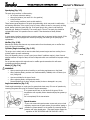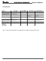
1
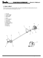
Owner’
s Man
ual
Owner’s
Manual
Model Numbers:
P/N 28575
Date 02-27-01
TPE-2501,TPE-2510
TPE-250PF
,TPE-270PF/PN
TPE-250PF,TPE-270PF/PN
POLE EDGERS
TPE-2510
TPE-270PF
Supplier To The Outdoor Power Equipment Industry
ISM, Inc. • 1028 4th Street SW • Auburn, WA 98001 • Phone: (253) 333-1200 • Fax: (253) 333-1212
www.tanakapowerequipment.com
[email protected]
TPE-2501,TPE-2510,TPE-270PF/PN,TPE-250PF
Owner’s Manual
Before using this unit:
•
•
•
Read the operator’s manual carefully.
Check that the cutting equipment is correctly assembled
and adjusted.
Start the unit and check the carburetor adjustment.
See “Maintenance”.
WARNING
The engine exhaust from this product
contains chemicals known to the State
of California to cause cancer, birth
defects and other reproductive harm.
Always wear eye, head and ear
protectors when using this unit.
Read, understand and follow all
warnings and instructions in this
manual and on the unit.
It is important that you read, fully understand and
observe the following safety precautions and
warnings. Careless or improper use of the unit
may cause serious or fatal injury.
Keep all children, bystanders and helpers 15m
(50ft.) away from the unit. If anyone
approaches you, stop the engine and cutting
attachment immediately.
www.tanaka-usa.com
1
[email protected]
TPE-2501,TPE-2510,TPE-270PF/PN,TPE-250PF
Owner’s Manual
1. What is What?
Since this manual covers several models, there may be some difference between pictures and your
unit. Use the instructions that apply to your unit.
1. Fuel Cap
2. Throttle Trigger
3. Starter Handle
4. Blade guard
5. Blade
6. Drive shaft pipe
7. Loop handle
8. Spark plug
9. Ignition Switch
10. Depth guide wheel
11. Lock Button
12. Knob nut
13. Choke lever
www.tanaka-usa.com
2
[email protected]
TPE-2501,TPE-2510,TPE-270PF/PN,TPE-250PF
2. Warnings and safety instructions
WARNING!
Anti-vibration systems do not guarantee that you will not
sustain white finger disease or carpel tunnel syndrome.
Therefore, continual and regular users should monitor closely
the condition of their hands and fingers. If any of the above
symptoms appear, seek medical advice immediately.
Operator safety
•
Always wear a safety face shield or goggles.
•
Always wear heavy, long pants, boots and gloves. Do
not wear loose clothing, jewelry, short pants, sandals
or go barefoot. Secure hair so it is above shoulder
length.
•
Do not operate that tool when you are tired, ill or
under the influence of alcohol, drugs or medication.
•
Never let a child or inexperienced person operate the
machine.
•
Wear hearing protection.
•
Never start or run the engine inside a closed room or
building. Breathing exhaust fumes can kill.
•
Keep handles free of oil and fuel.
•
Keep hands away from cutting equipment.
•
Do not grab or hold the unit by the cutting
equipment.
•
When the unit is turned off, make sure the cutting
attachment has stopped before the unit is set down.
•
When operation is prolonged, take a break from time
to time so that you may avoid possible white finger
disease which is caused by vibration.
Tool safety
•
Inspect the entire tool before each use. Replace
damaged parts. Check for fuel leaks and make sure
all fasteners are in place and securely fastened.
•
Replace parts that are cracked, chipped or damaged
in any way before using the tool.
•
Make sure the safety guard is properly attached.
•
Keep others away when making carburetor
adjustments.
•
Use only accessories as recommended for this tools
by the manufacturer.
WARNING!
Never modify the tool in any way. Do not use your cutting tool
for any job except that for which it is intended.
Fuel safety
NOTE!
•
Empty the fuel tank before storing the tool.
Especially, in case of over three month storage,
it is a must otherwise fuel may corrode causing
carburetor damage. It is recommended that
the fuel be emptied after each use. If fuel is
left in the tank, store so fuel will not leak.
•
Mix and pour fuel outdoors and where there are no
sparks or flames.
•
Use a container approved for fuel.
•
Do not smoke or allow smoking near fuel or the tool
or while using the tool.
•
Wipe up all fuel spills before starting engine.
•
Move at least 3 m (10ft.) away from fueling site
before starting engine.
•
Stop engine before removing fuel cap.
•
Empty the fuel tank before storing the tool. It is
recommended that the fuel be emptied after each
use. If fuel is left in the tank, store so fuel will not
leak.
•
Store tool and fuel in area where fuel vapors cannot
reach sparks or open flames from water heaters,
electric motors or switches, furnaces, etc.
www.tanaka-usa.com
Owner’s Manual
Cutting safety
•
Inspect the area to be cut before each use. Remove
objects which can be thrown or become entangled.
•
For respiratory protection, wear an aerosol protection
mask when cutting the grass after insecticide is
scattered.
•
Keep others including children, animals, bystanders
and helpers outside the 15 m hazard zone. Stop the
engine immediately if you are approached.
•
Always keep the engine on the right side of your
body.
•
Hold the tool firmly with both hands.
•
Keep firm footing and balance. Do not over-reach.
•
Keep all parts of your body away from the muffler
and cutting attachment when the engine is running.
•
Keep cutting attachment below waist level.
Maintenance safety
•
Maintain the tool according to recommended
procedures.
•
Disconnect the spark plug before performing
maintenance except for carburetor adjustments.
•
Keep others away when making carburetor
adjustments.
•
Use only genuine replacement parts as recommended
by the manufacturer.
Transport and storage
•
Carry the tool by hand with the engine stopped and
the muffler away from your body.
•
Allow the engine to cool, empty the fuel tank, and
secure the tool before storing or transporting in a
vehicle.
•
Empty the fuel tank before storing the tool. It is
recommended that the fuel be emptied after each
use. If fuel is left in the tank, store so fuel will not
leak.
•
Store tool out of the reach of children.
•
Clean the unit carefully and store it in a dry place.
•
Make sure engine switch is off when transporting or
storing.
•
When transporting in a vehicle, cover blade with
blade cover.
If situations occur which are not covered in this manual, take
care and have a good judgment. Contact your dealer if you
need assistance.
Pay special attention to statements preceded by the following
words:
WARNING!
Indicates a strong possibility of severe personal injury or loss
of life, if instructions are not followed.
CAUTION!
Indicates a possibility of personal injury or equipment damage,
if instructions are not followed.
NOTE!
Helpful information for correct function and use.
3
[email protected]
TPE-2501,TPE-2510,TPE-270PF/PN,TPE-250PF
Owner’s Manual
3. Assembly procedures.
Drive shaft to engine (Fig. 1 -1)
Loosen tube locking bolt (1) about ten turns so that the bolt point
will not obstruct drive shaft tube to be inserted. When inserting
drive shaft tube, hold the tube locking bolt outward preventing
inside fitting from obstructing as well.
Insert the drive shaft into the clutch case of the engine properly
until the marked position (2) on the drive shaft tube meets the
clutch case.
NOTE!
When it is hard to insert drive shaft up to the marked position on
the drive shaft tube, turn drive shaft by the cutter mounting end
clockwise or counterclockwise. Tighten tube locking bolt lining up
the hole in the shaft tube.
Then tighten clamp bolt securely (3).
Installation of handle (Fig. 1-2)
Attach the handle to the drive shaft tube with the angle towards the
engine.
Adjust the location to the most comfortable position before
operation.
Throttle wire/stop cord
Remove air cleaner cover. (Fig. 1-3)
Connect stop cords. (Fig. 1 -4)
Connect throttle wire end to carburetor. (Fig. 1 -5)
Cover throttle wire and stop cords together with protective tube provided up to air cleaner cover. (Fig. 1-6)
www.tanaka-usa.com
4
[email protected]
TPE-2501,TPE-2510,TPE-270PF/PN,TPE-250PF
Owner’s Manual
Installation of blade guard (Fig. 1-7)
1) Install blade guard (1) on gear case (4) temporarily by clamping with guard brackets (2)
and screws (3). Then tighten as needed.
2) Line up the slot of guard bracket (2) with the same of gear case (4), then tighten screws
(3) securely. (Fig. 1-7B)
Installation of wheel (Fig. 1-7C)
1) Installation the wheel as the illustration.
2) After installation, check if the wheel turns
smoothly.
Installation of blade (Fig. 1-8)
1) Before installation of blade, take off left hand
threaded fixing nut (1), cutter holder cap (2) from the
blade shaft.
2) Install blade (3) on the shaft and then replace the
cutter holder cap and fixing nut in order.
NOTE!
When installing cutter holder cap (2), be sure to set
concave side facing blade.
3) Insert the locking bar (4) into the hole of the cutter
holder (5) and gear case by lining up each hole.
4) Tighten the fixing nut securely (clockwise to
loosen/counter-clockwise to tighten).
www.tanaka-usa.com
5
[email protected]
TPE-2501,TPE-2510,TPE-270PF/PN,TPE-250PF
Owner’s Manual
4. Operating procedures.
WARNING!
This unit is equipped with a two-stroke engine. Always run the engine on fuel, which is mixed with oil.
Provide good ventilation, when fueling or handling fuel.
Fuel
•
Always use branded 89 octane unleaded gasoline.
•
Use Tanaka two-cycle oil or a quality two-cycle oil at mixing ratio of 25-50:1 (Gasoline (A) : Oil (B)), only for the
state of California at 50: 1.
•
Never use multi-grade oil (10 W/30) or waste oil.
•
Always mix fuel and oil in a separate clean container.
Always start by filling half the amount of fuel, which is to be used. Then add the whole amount of oil. Mix (shake) the fuel
mixture.
Add the remaining amount of fuel.
Mix (shake) the fuel-mix thoroughly before filling the fuel tank.
Fueling
WARNING!
•
Always shut off the engine before refueling.
•
Slowly open the fuel tank, when filling up with fuel, so that possible over-pressure disappears.
•
Tighten the fuel cap carefully, after fueling.
•
Always move the unit at least 3 m (10 ft.) from the fueling area before starting.
Before fueling, clean the tank cap area carefully, to ensure that no dirt falls into the tank.
Make sure that the fuel is well mixed by shaking the container, before fueling.
www.tanaka-usa.com
6
[email protected]
TPE-2501,TPE-2510,TPE-270PF/PN,TPE-250PF
Owner’s Manual
Starting (Fig. 2-2)
CAUTION!
Before starting, make sure the cutting attachment does not touch anything.
1. Set ignition switch (1) to ON position.
*Push priming bulb (4) several times so that fuel flows through bulb into carburetor. (if so equipped)(Fig. 2-2B,3)
2. With the safety lever (2) pressed (if so equipped), pull throttle trigger and push lock button (3), then slowly release the
throttle trigger first, then the safety lever. This will lock the throttle in starting position.
3. Set choke lever to CLOSED position (5). (Fig. 2-2B,3)
4. Pull recoil starter briskly, taking care to keep the handle in your grasp and not allowing it to snap back.
5. When you hear the engine want to start, return choke lever to RUN position (open). Then pull recoil starter briskly
again.
NOTE!
If engine does not start, repeat procedures from 2 to 5.
6. After starting engine, pull throttle lever to release lock button.
Cutting (Fig. 2-4,2-4B)
Use edger properly. Use only for edging the type of grass and other growth for which the
machine is designed. Do not abuse engine.
1) Adjust cutting depth by loosening knob nut (1) and moving location of wheel up or down. To
increase cutting depth, move the wheel location upwards and to decrease, move it lower. After
the location is decided, tighten knob nut (1) securely.
NOTE!
The adjustment should be made after engine stopped completely and stop switch is in stop
position.
2) Always hold unit firmly with both hands and keep your body well balanced. 3) Always operate
the power edger positioned at the right-side of the operator. (Fig. 2-4C)
WARNING!
Operate the unit from position where guards block the line of sight to the cutting blade.
WARNING!
If cutter should strike against stones or other debris, stop the engine and make sure that the
cutter and related parts are undamaged. When grass or vines wrap around cutler, stop engine
and blade and remove it.
Stopping (Fig. 2-5)
Decrease engine speed and run at an idle for a few minutes, then
turn off ignition switch.
WARNING!
A blade can injure while it continues to spin after the engine is
stopped or power control is released. When the unit is turned off,
make sure the cutting attachment has stopped before the unit is set
down.
www.tanaka-usa.com
7
[email protected]
TPE-2501,TPE-2510,TPE-270PF/PN,TPE-250PF
Owner’s Manual
5. Maintenance.
MAINTENANCE, REPLACEMENT, OR RE PAIR OF THE EMISSION CONTROL DEVICES
AND SYSTEMS MAY BE PERFORMED BY ANY NONROAD ENGINE REPAIR
ESTABLISHMENT OR INDIVIDUAL.
Carburetor adjustment (Fig. 3-1)
WARNING!
The cutting attachment may be spinning during carburetor adjustments.
WARNING!
Never start the engine without the complete clutch cover and tube assembled! Otherwise the
clutch can come loose and cause personal injuries.
In the carburetor, fuel is mixed with air. When the engine is test run at the factory, the
carburetor is basically adjusted. A further adjustment may be required, according to climate
and altitude. The carburetor has one adjustment possibility:
T = Idle speed adjustment screw.
Idle speed adjustment (T)
Check that the air filter is clean. When the idle speed is correct, the blade will not rotate. If adjustment is required, close
(clockwise) the T-screw, with the engine running, until the blade starts to rotate. Open (counterclockwise) the screw until
the blade stops.
You have reached the correct idle speed when the engine runs smoothly in all positions well below the rpm when the
blade starts to rotate. If the blade still rotates after idle speed adjustment, contact your service workshop.
NOTE!
Standard Idle rpm is 2500-3000 rpm.
WARNING!
When the engine is idling the blade must under no circumstances rotate.
Air filter (Fig. 3-2)
The air filter must be cleaned from dust and dirt in order to avoid:
•
Carburetor malfunctions.
•
Starting problems.
•
Engine power reduction.
•
Unnecessary wear on the engine parts.
•
Abnormal fuel consumption.
Clean the air filter daily or more often if working in exceptionally dusty areas.
Cleaning the air filter
Remove the air filter cover and the filter (1).
Rinse it in warm soap suds. Check that the filter is dry before reassembly. An air filter that
has been used for some time cannot be cleaned completely. Therefore, it must regularly be replaced by a new one. A
damaged filter must always be replaced.
Fuel filter (Fig. 3-2B)
Drain all fuel from fuel tank and pull fuel filter line from tank. Pull filter element out of
holder assembly. Replace filter if it appears to be discolored or hardened from use.
The filter has a white, felt-like appearance when new.
www.tanaka-usa.com
8
[email protected]
TPE-2501,TPE-2510,TPE-270PF/PN,TPE-250PF
Owner’s Manual
Spark plug (Fig. 3-3)
The spark plug condition is influenced by:
• An incorrect carburetor setting.
• Wrong fuel mixture (too much oil in the gasoline)
• A dirty air filter.
• Hard running conditions (such as cold weather).
These factors cause deposits on the spark plug electrodes, which may result in malfunction
and starting difficulties. If the engine is low on power, difficult to start or runs poorly at idling
speed, always check the spark plug first. If the spark plug is dirty, clean it and check the
electrode gap. Readjust if necessary. The correct gap is 0.6 mm. The spark plug should be
replaced after about 100 operation hours or earlier if the electrodes are badly eroded.
NOTE!
In some areas, local law requires using a resistor spark plug to suppress ignition signals. If this
machine was originally equipped with resistor spark plug, use same type of spark plug for
replacement.
Muffler (Fig. 3-3B)
Remove the muffler and clean out any excess carbon from the exhaust port or muffler inlet
every 100 hours of operation.
Cylinder (Engine cooling) (Fig. 3-3C)
The engine is air cooled, and air must circulate freely around engine and over cooling fins on
cylinder head to prevent overheating.
Every 100 Operating hours, or once a year (more often if conditions require), clean fins and
external surfaces of engine of dust, dirt and oil deposits which can contribute to improper cooling.
NOTE!
Do not operate engine with engine shroud or muffler guard removed as this will cause
overheating and engine damage.
Blade (1) (Fig. 3-4)
WARNING!
• Wear protective gloves when handling or performing maintenance on the blade.
• When replacing blade, purchase one recommended by TANAKA, with a 25.4mm (one
inch) fitting hole.
•
•
•
Use correct blade for the type of work.
When replacing blade, use appropriate tools.
Discard blades that are bent, warped, cracked, broken or damaged in any way.
Angle transmission (Fig. 3-5)
Check angle transmission or angle gear for grease level about every 50 hours of operation by
removing the grease filler plug on the side of angle transmission.
If no grease can be seen on the flanks of the gears, fill the
transmission with a quality lithium based multipurpose grease up
to 3/4.
Do not completely fill the transmission.
Spark Arrestor
If your unit comes with spark arrestor screen and yet your local
regulation requires use of spark arrestor for prevention against a
possible fire, please attach it to the muffler by removing muffler
protector and other related parts. (The spark arrestor meets the
regulation of SAE J335-SEP90 and CSA CAN3-Z62.1-M77.)
www.tanaka-usa.com
9
[email protected]
TPE-2501,TPE-2510,TPE-270PF/PN,TPE-250PF
Owner’s Manual
Maintenance schedule
Below you will find some general maintenance instructions.
For further information please contact your service dealer.
Daily maintenance
•
Clean the exterior of the unit.
•
Check the blade guard for damage or cracks. Change the guard in case of impacts or cracks.
•
Check that the cutting attachment is properly centered, sharp, and without cracks. As off-centered
cutting attachment induces heavy vibrations that may damage the unit.
•
Check that the cutting attachment nut is sufficiently tightened.
•
Check that nuts and screws are sufficiently tightened.
Weekly maintenance
•
Check the starter, especially cord and return spring.
•
Clean the exterior of the spark plug.
•
Remove it and check the electrode gap. Adjust it to 0.6 mm, or change the spark plug.
•
Clean the cooling fins on the cylinder and make sure the air intake at the starter is not clogged.
•
Check that the angle gear is filled with grease up to ¾.
•
Clean the air filter.
Monthly maintenance
•
Rinse the fuel tank with gasoline.
•
Clean the exterior of the carburetor and the space around it.
•
Clean the fan and the space around it.
www.tanaka-usa.com
10
[email protected]
TPE-2501,TPE-2510,TPE-270PF/PN,TPE-250PF
Owner’s Manual
6. Specifications
Model
Engine Size
Carburetion
System (Optional)
Spark Plug
Fuel
Fuel Tank Capacity
(l)
Dry Weight (kg)
Standard and/or
Optional
Accessories
TPE-250PF
TPE-2510
24 ml (1.4 cu. in.)
Walbro Diaphragm
(w/Priming Pump)
TPE-2501
!
!
!
!
NGK BM-7A or equivalent
!
Mixed Fuel of Gasoline &
2-cycle engine oil at 25~50:1
0.50 (16.9 fl. oz.)
5.9 (13.0 lbs)
Steel Cutting Blade
TPE-270PF/PN
26 ml (1.58 cu. in.)
!
!
NGK BPM 6-A or
equivalent
!
CHAMPION CJ6Y or
equivalent
!
!
0.76 (25.7 fl. oz.)
0.65 (22.0 fl. oz.)
6.0 (13.2 lbs.)
!
6.1 (13.4 lbs.)
!
6.7 (14.7 lbs)
!
Note: To improve the performance, the specifications are subject to change without notice.
www.tanaka-usa.com
11
[email protected]