1
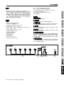
CA240/CA240B English Deutsch Español CA35 CA60 CA120(B) CA240(B) Français Português 日本語 简体中文 User's Manual Benutzerhandbuch Manual del Usuario Mode d'emploi Manual do Usuário ユーザーズマニュアル 使用手册 English CA35/CA60 CA120(B)/CA240(B) Deutsch Mixer/Amplifier Mezclador/Amplificador 公共广播处理系统 Español ENGLISH . . . . . . . . . . . . . . . . . . . . . . . . . . . . . . . . . . . . . I ESPAÑOL . . . . . . . . . . . . . . . . . . . . . . . . . . . . . . . . . . . . . II Français 简体中文 . . . . . . . . . . . . . . . . . . . . . . . . . . . . . . . . . . . . . III Português 日本語 简体中文 V1.1 09/02/2011 CONTENTS FEATURES.............................................................................1 F R O N T PA N E L . . . . . . . . . . . . . . . . . . . . . . . . . . . . . . . . . . . . . . . . . . . . . . . . . . . 1 R E A R PA N E L . . . . . . . . . . . . . . . . . . . . . . . . . . . . . . . . . . . . . . . . . . . . . . . . . . . . . . . 2 OUTPUT WIRING.............................................3 SPECIFICATIONS................................................................4 APPENDIX DIMENSIONS.......................................................................2 Phonic preserves the right to improve or alter any information within this document without prior notice Français APPLICATION.......................................................................1 Español INPUT WIRING.................................................3 Deutsch INTRODUCTION....................................................................1 English USER'S MANUAL Português 日本語 简体中文 IMPORTANT SAFETY INSTRUCTIONS English with liquids, such as vases, The apparatus shall not be exposed to dripping or splashing and that no objects shall be placed on the apparatus. The MAINS plug is used as the disconnect device, the disconnect device shall remain readily operable. Warning: the user shall not place this apparatus in the can be easily accessible. area during the operation so that the mains switch 1. Read these instructions before operating this apparatus. Deutsch CAUTION 2. Keep these instructions for future reference. RISK OF ELECTRIC SHOCK DO NOT OPEN 3. Heed all warnings to ensure safe operation. 4. Follow all instructions provided in this document. 5. Do not use this apparatus near water or in locations where condensation may occur. Español 6. Clean only with dry cloth. Do not use aerosol or liquid cleaners. Unplug this apparatus before cleaning. 7. Do not block any of the ventilation openings. Install in accordance with the manufacturer’s instructions. Français 8. Do not install near any heat sources such as radiators, heat registers, stoves, or other apparatus (including . Português 9. Do not defeat the safety purpose of the polarized or grounding-type plug. A polarized plug has two blades with one wider than the other. A grounding type plug has two blades and a third grounding prong. The wide blade or the third prong is provided for your safety. If the provided plug does not into your outlet, consult an electrician for replacement of the obsolete outlet. 10. Protect the power cord from being walked on or pinched particularly at plug, convenience receptacles, and the point where they exit from the apparatus. 11. Only use attachments/accessories manufacturer. by the 日本語 12. Use only with a cart, stand, tripod, bracket, or table by the manufacturer, or sold with the apparatus. When a cart is used, use caution when moving the cart/apparatus combination to avoid injury from tipover. 简体中文 13. Unplug this apparatus during lighting storms or when unused for long periods of time. service personnel. 14. Refer all servicing to Servicing is required when the apparatus has been damaged in any way, such as power-supply cord or plug is damaged, liquid has been spilled or objects have fallen into the apparatus, the apparatus has been exposed to rain or moisture, does not operate normally, or has been dropped. CAUTION: TO REDUCE THE RISK OF ELECTRIC SHOCK, DO NOT REMOVE COVER (OR BACK) NO USER SERVICEABLE PARTS INSIDE REFER SERVICING TO QUALIFIED PERSONNEL The lightning flash with arrowhead symbol, within an equilateral triangle, is intended to alert the user to the presence of uninsulated “dangerous voltage” within the product’ magnitude to constitute a risk of electric shock to persons. The exclamation point within an equilateral triangle is intended to alert the user to the presence of important operating and maintenance (servicing) instructions in the literature accompanying the appliance. WARNING: To reduce the risk of or electric shock, do not expose this apparatus to rain or moisture. CAUTION: Use of controls or adjustments or performance may result in of procedures other than those hazardous radiation exposure. INTRODUCTION 4 2 5 日本語 3 Português 6 Français 1 Español z Three-channel mixer/amplifier (CA35) z Four-channel mixer/amplifier (CA60) z Six-channel mixer/amplifier (CA120 and CA240) z Three output operating modes: 8 ohms, 70V and 100V z Output power of 35W, 60W, 120W or 2x120W (for the 35, 60, 120 and 240 respectively) z Wide frequency response of 70 Hz to 18 kHz ±2dB z Low distortion and ultra-low noise level z Master bass and treble controls z User-assignable zone 2 output z Balanced channel 1 input z Telephone paging output z User-controlled VOX priority z +24V phantom power for mics z Chime and Announce tones built into CA120 and CA240 z Two, three or four RCA input connectors (model dependent) z Input channel 2 offers XLR and ¼” TRS jacks on CA120 and CA240 1. Input Level Controls Controls in the input level control for the corresponding channels. 2. Master Level Control This controls the final output level before sending to the output connectors. 3. Master Output Indicators The green LED above the Master level control will light up when the output signal exceeds -40dB indicating that a signal is present. The red LED indicator will light up when the output signal reaches high peaks with the potential of causing distortion. 4. Bass Control Turning to the right will increase the response of low-frequency signals (100 Hz) in your main audio signal. Turning to the left will decrease the response of low-frequency signals. 5. Treble Control Turning to the right will increase the response of high-frequency signals (10 kHz) in your main audio signal. Turning to the left will decrease the response of high-frequency signals. 6. Chime & Alert Tones These two buttons will send an alert or an announce tone through to the speakers. The alert button can also be used to activate a siren, the length of which will be 2 minutes and 30 seconds. Pushing the Alert button a second time will disengage the siren. The ‘’announce’ button will active a 3 second ‘do mi so do’ tone to indicate an announcement. Activating either of these tones will cut out all music and other input sources. 7. Power Button and Indicator This button turns the CA mixer/amplifier on. When the unit is turned on, the LED indicator will illuminate to indicate as such. Be sure that the mixer amplifier is turned on after all other input sources. Deutsch FEATURES FRONT PANEL English Congratulations on your purchase of a Phonic CA mixer/amplifier. These mixer/amplifiers can mix up to four or six individual signals with power output rated at 35, 60, 120 or 240 Watts. The CA series is ideal for small sound reinforcement systems. An additional zone 2 output with 8 ohm or 600 ohm output connections is included for versatile side fill or multi-zone operation. Users are able to set priority VOX operation with a variable threshold control. A +24V phantom power supply is included for condenser microphones. A number of stereo RCA connectors with summed inputs are onboard for inclusion of music sources. A transformer-isolated output connection is included with 8 ohms, 70V and 100V line output application possible. Variable bass and treble controls are available on the master output. z Versatile heat and voltage protection for the amplifier z 24V battery connection for rechargeable batteries (CA120B and CA240B) z Compact design and low weight 7 简体中文 CA35 / CA60 / CA120(B) / CA240(B) 1 9 17 18 10 11 12 8 English Deutsch 20 19 14 13 REAR PANEL 8. Input Amp Configuration Switches These DIP switches have a number of different functions. Español Français Português CH1 MicOn/LineOff When set to Off, it allows line-level signal input through channel 1. When set to On, it allows microphone-level signals through channel 1. CH1 Normal This switch sets channel 1 to normal, with no priorities. CH1 Priority Enables muting of channels when priority circuit on input 1 is closed. Connect the priority connection on Input 1 to microphone’s push-to-talk function when this is activated. CH1 VOX Activating this switch allows automatic muting when channel 1 input passes the preset threshold (point 10). CH1 to Zone 2 Activating this switch sends the channel 1 input signal to the zone 2 output channel. CH2 to Zone 2 Activating this switch sends the channel 2 input signal to the zone 2 output. CH3 to Zone 2 (CA35 and CA60 only) Activating this switch sends the channel 3 input signal to the zone 2 output. 日本語 Activating this switch will reduce CH2 PAD the input signal level of channel 2 (CA120 and CA240 only) by 20 dB making it ideal for lowimpedance devices. Phantom Power This switch activates phantom power to the Input 1 input. Phantom power is required for use with condenser microphones. 简体中文 9. Input 1 Terminal This is a 5-pin Phoenix-type connection with 3 pins for balanced input signals and 2 connectors for priority push-to-talk button connection. The input accepts direct connection of line or microphone inputs as selected by the mic/line DIP switch (point 8). 10. Input 1 VOX Threshold Control This control adjusts the level at which the Input 1 signal should be before other signals are muted. This only works when the CH1 VOX DIP switch is turned on. 2 11. XLR Inputs (CA120 and CA240 only) Channel 2 on the CA120 and CA240 offers users with an XLR microphone input, ideal for input of microphones. 12. ¼” Inputs (CA120 and CA240 only) The CA120 and CA240 offer unbalanced ¼” phone jack input connectors input channels 2 through 13. 1/8” Mini-stereo Inputs (CA120 and CA240 only) Channel 6 of the CA120 and CA240 also offers 1/8” mini-stereo input connectors, similar to those used on laptops, iPods and other MP3 players. 14. RCA Inputs These inputs accept stereo unbalanced line-level RCA input signals. The input signals received by these connectors are summed. 15. Zone 2 / MOH Output and Control This 4-pin Phoenix-type connector provides two different output possibilities. The 8 ohm side is for 1W output to external speakers, while the 600 ohm connectors are for connecting private branch exchange (PBX) telephone systems for on-hold music. For further info on wiring, see the Output Wiring section. 16. Preamp Output Terminal (CA35 and CA60 only) This balanced 3-pin Phoenix type connection sends the CA35 and CA60 mixer/amplifier’s signal to external devices. The output signal level is dependent on the master level control. For further info on wiring, see the Output Wiring section. 17. Link Output (CA120 and CA 240) This unbalanced ¼” phone jack output takes the pre-fader main output signal of the amplifier to sent it to external devices. 18. Link Input (CA120 and CA240) This unbalanced ¼” phone jack input allows users to incorporate external signals directly into the CA120 and CA240’s main mix. 19. Amplifier Output Speakers can be connected to this output terminal. Connections available include COM (common), 70V, 100V and 8 ohms. These input connections can accept terminal forks up to 10 AWG. For further info on wiring, see the Output Wiring section. 20. Power Cable The CA series’ has a preinstalled power cable. Please connect the cable to a suitable AC power outlet. While the CA series offers a universal power supply, be sure to check local voltage levels before connecting the unit to ensure they correspond. 21. 24V Battery Input and Charging Switch (‘B’ models only) These banana-plug input connectors can be connected to the positive and negative terminals of a 24V DC power source. This allows the unit to function even in the vent of power outages. The 21 switch located above these connections is used to activated and deactivate the charging circuit. It is advised not to leave the battery in charge mode when already fully charged. CA35 / CA60 / CA120(B) / CA240(B) OUTPUT WIRING Phonic recommends that customers use pre-build balanced line connectors with 22 to 24 gauge cable. Unbalanced connections could also be used however are susceptible to noise. Speakers Priority Muting Zone 2 / MOH External music sources can be sent over phone lines while a caller is on hold using the Phonic CA series. Connections can be completed as indicated below using either the 8 ohm or 600 ohm connections. Connect the Zone 2/MOH to your telephone system or PBX’s music-on-hold input. WARNING: Do not use shielded cable for output power wiring. Phonic recommends use of 2-conductor shielded cable and 3-pin Phoenix-type connectors for Preamp Line output. Deutsch The Phonic CA mixer/amplifier allows users to mute background signals in favour of the microphone/line input 1 signal. To use a microphone’s push-to-talk switch, first connect the mic’s pushto-talk contact switch to the priority connector of the Mic/Line input. Ensure the VOX Normal DIP switch is set to OFF and the VOX Priority DIP switch is set to ON. This enables users to mute all other signals when the microphone’s push-to-talk button is engaged. Outputs can be made to by slipping cable lugs underneath the output screw terminals. Tighten screws to fasten in place. Customers may choose to use crimp-on spade lugs. Phonic recommends that customers use professionally wired high gauge cables. The plastic cover can be slid into place to protect connections. It is recommended that you insulate exposed wires to help prevent against the possibility of short-circuits. Class 2 wiring is required. English INPUT WIRING Español Français Português Totelephone system interface/PBX input 日本語 简体中文 CA35 / CA60 / CA120(B) / CA240(B) 3 SPECIFICATIONS English Deutsch Español Français Português CA35 CA60 35W 60W 2 3 1/4” Phone Jack Inputs N/A N/A 3.5mm Mini-Stereo Phone Jack N/A N/A 70Hz to 18kHz ±2dB 70Hz to 18kHz ±2dB 1 1 N/A N/A Balanced Screw Terminal Output Yes Yes Balanced Phoenix Output Yes Yes Zone 2 (Telephone Use) Yes Yes 70V Output Yes Yes 100V Output Yes Yes All>60dB All>60dB Input Signal LED Yes Yes Master Out Clip LED Yes Yes Treble & Bass (Output) Yes Yes Alert & Announce Chimes N/A N/A VOX Threshold Yes Yes Number of Input Channels 3 4 Input Volume Control 3 4 Master Out Level Control 1 1 < 0.5% < 0.5% 14~15V DC 14~15V DC 241 x 105 x 352 mm (9.49” x 4.13” x 13.86”) 241 x 105 x 352 mm (9.49” x 4.13” x 13.86”) Power Output (Rated) Input Section RCA Input Frequency Response Phoenix Input Link In Output Section S/N Ratio THD@ 1kHz (10% Rated Output) Phantom Power Dimensions (WxHxD) 日本語 简体中文 4 CA35 / CA60 / CA120(B) / CA240(B) CA120B CA240 CA240B 120W 120W 120W+120W 120W+120W RCA Input 4 4 4 4 1/4” Phone Jack Inputs 3 3 3 3 3.5mm Mini-Stereo Phone Jack 1 1 1 1 70Hz to 18kHz ±2dB 70Hz to 18kHz ±2dB 70Hz to 18kHz ±2dB 70Hz to 18kHz ±2dB 1 1 1 1 Yes Yes Yes Yes Balanced Screw Terminal Output Yes Yes Yes Yes Balanced Phoenix Output Yes Yes Yes Yes Zone 2 (Telephone Use) Yes Yes Yes Yes 70V Output Yes Yes Yes Yes 100V Output Yes Yes Yes Yes All>60dB All>60dB All>60dB All>60dB Input Signal LED Yes Yes Yes Yes Master Out Clip LED Yes Yes Yes Yes Treble & Bass (Output) Yes Yes Yes Yes Alert & Announce Chimes Yes Yes Yes Yes VOX Threshold Yes Yes Yes Yes Number of Input Channels 6 6 6 6 Input Volume Control 6 6 6 6 Master Out Level Control 1 1 1 1 < 0.5% < 0.5% < 0.5% < 0.5% NA 14~15V DC NA 14~15V DC 483 x 105 x 293 mm (19.02” x 4.13” x 11.54”) 483 x 105 x 293 mm (19.02” x 4.13” x 11.54”) 483 x 105 x 293 mm (19.02” x 4.13” x 11.54”) 483 x 105 x 293 mm (19.02” x 4.13” x 11.54”) Power Output (Rated) English CA120 Input Section Phoenix Input Link In Deutsch Frequency Response Output Section 日本語 Dimensions (WxHxD) Português Phantom Power Français THD@ 1kHz (10% Rated Output) Español S/N Ratio 简体中文 CA35 / CA60 / CA120(B) / CA240(B) 5 SERVICE AND REPAIR For replacement parts, service and repairs please contact the Phonic distributor in your English country. Phonic does not release service manuals to consumers, and advice users to not attempt any self repairs, as doing so voids all warranties. You can locate a dealer near you at http://www.phonic.com/where/. Deutsch WARRANTY INFORMATION Español Phonic stands behind every product we make with a no-hassles warranty. Warranty coverage may be extended, depending on your region. Phonic Corporation warrants this product for a minimum of one year from the original date of purchase against defects in material and workmanship under use as instructed by the user’s manual. Phonic, at its option, shall repair or replace the defective unit covered by this warranty. Please retain the dated sales receipt as evidence of the date of purchase. You will need it for any warranty service. No returns or repairs will be accepted without a proper RMA number (return merchandise authorization). In order to keep this warranty in effect, the product must have been handled and used as prescribed in the instructions accompanying this warranty. Any tampering of the product or attempts of self repair voids all warranty. This warranty does not cover any damage due to accident, misuse, abuse, or negligence. This warranty is valid only if the product was purchased new from an authorized Phonic dealer/distributor. For complete warranty policy information, please visit http://www.phonic.com/warranty/. Français CUSTOMER SERVICE AND TECHNICAL SUPPORT Português We encourage you to visit our online help at http://www.phonic.com/support/. There you can find answers to frequently asked questions, tech tips, driver downloads, returns instruction and other helpful information. We make every effort to answer your questions within one business day. 日本語 简体中文 [email protected] http://www.phonic.com 6 CA35 / CA60 / CA120(B) / CA240(B) CONTENTS English MANUAL DEL USUARIO INTRODUCCIÓN....................................................................1 PA N E L F R O N TA l . . . . . . . . . . . . . . . . . . . . . . . . . . . . . . . . . . . . . . . . . . . . . . . . . . . 1 PA N E L P O S T E R I O R . . . . . . . . . . . . . . . . . . . . . . . . . . . . . . . . . . . . . . . . . . . . . . 2 ENCABLADO DE ENTRADA...................................3 Deutsch CARACTERÍSTICAS......................................................1 ENCABLADO DE SALIDA...............................3 APÉNDICE APLICACIONES........................................................1 Español ESPECIFICACIONES.....................................................4 DIMENSIONES................................................................2 Français Phonic se reserva el derecho de mejorar o alterar cualquier información provista dentro de este documento sin previo aviso. Português 日本語 简体中文 English Deutsch Español Français Português 日本語 简体中文 INTRODUCCIÓN z z 3 4 2 5 日本語 6 Português 1 Français z z z z z z z z z Tres canales mezclador/amplificador (CA35) Cuatro canales mezclador/amplificador (CA60) Sies canales mezclador/amplificador (CA120 y CA240) Tres salida de modo operativo: 8 ohms, 70V y 100V Salida de potencia of 35W, 60W, 120W o 2x120W (para 35, 60, 120 y 240 respectivamente) Ancha respuesta de frecuencia de 70 Hz a 18 kHz ±2dB Baja distorción y nivel de ruido ultra-bajo Master bass y controles treble Usuario-asignable zona 2 salida Entrada canal 1 balanceado Salida de paginación teléfono Controlador-usuario VOX prioridad +24V fuente fantasma para micrófonos Chime y tonos de anunciado contruidos dentro del CA120 y CA240 Dos, Tres or cuatro conectores de entrada RCA (modelo dependiente) Entrada de canal 2 ofrece XLR y ¼” TRS jacks en CA120 y CA240 Español z z z z z 1. Controles de Nivel Entrada Controla el control de nivel de entrada para los canales correspondientes. 2. Control Master de Nivel Este controla la salida final de nivele antes de ser enviados a la salida de conectores. 3. Indicadores de Salida Master El LED verde sobre el control de nivel Master se iluminará cuando la señal de salida sobrepase -40dB indicando que la señal esta presente. El indicador del LED rojo se encenderá cuando la señal de salida llegue al pico alto con el potencial de causar distorción. 4. Control Bass Girando a la derecha incrementará la respuesta de las señales de baja-frecuencia (100 Hz) en su señal audio central. Y girando a la izquierda disminuirá la respuesta de señales de bajafrecuencia. 5. Control Treble Girando a la derecha incrementará la respuesta de señal de altafrecuencia(10 kHz) en su señal de audio central. Y girando a la izquierda disminuirá las señales de alta-frecuencia. 6. Tonos de Chime & Alerta Estos dos botones enviarán un tono de alerta o anunciado mediante los altavoces. El botón de alerta puede ser usado para activar una sirena, con el espacio que será 2 minutos y 30 segundos. Presionando el botón Alerta una segúnda vez desactivará la sirena. El botón de ¨anunciado¨ será activado a los 3 segundos con tonos de ¨do mi so do¨ para indicar el anunciado. Activando cualqueira de estos tonos cortará toda música y otras fuentes de entrada. 7. Botón de Potencia e Indicador Este botón enciende el mezclador/amplificador CA. Cuando esta unidad está encendida, el indicador LED se iluminará para indicarlo. Asegúrese que el mezclador amplificadora esté encendida después de todas las fuentes de entrda. Deutsch CARACTERÍSTCAS PANEL FRONTAL English ¡Felicitaciones! Por la compra de la mezclador/amplificador CA de Phonic. Estas mezcladoras/amplificadoras pueden hacer fusiones de hasta cuatro o seis señales individuales con salida de potencia estimada a 35,60,120 o 240 Watts. La serie de CA es lo ideal para sistemas de renforzamiento de sonidos pequeños. Una salida de zona 2 en adición con conexión salida de 8 ohm o 600 ohm es incluida para una operación versátil de rellando lateral o multi-zona. Los usuarios pueden configurar la operación prioritaria VOX con controles de umbral variable. Un +24V suministro de fuente fantasta es incluido para micrófonos condesadores. Un número de conectres RCA estéreo suma entradas abordo para la incluir fuentes de música. Un transformador-aislado salida de conexión es incluido con 8ohms, 70V y 100V línea de salida de aplicaciones posibles. Variados controles de bass y treble estan disponibles en las salidas master. z Protección versatile de calentamiento y voltaje para el amplificador z 24V connexion de bateria para baterias recargables (CA120B y CA240B) z Diseño compacto y ligero peso 7 简体中文 CA35 / CA60 / CA120(B) / CA240(B) 1 9 17 18 10 11 12 8 English Deutsch 20 19 14 13 PANEL POSTERIOR 8. Interruptores para Configuración del Amp de Entrada Estos interruptores DIP tienen un número de diferentes funciones. Español CH1 MicOn/ LíneaOff Cuando al estar en OFF, permite la entrada de señal de línea-nivel por el canal 1. Cuando este en ON, permite señales de micrófononivel mediante canal 1. Français Este interruptor configura canal 1 a normal, sin prioridades. Activa enmudecimiento cuando el circuito de prioridad en la entrada 1 está cerrada. CH1 Prioridad Conecta la conexión prioritaria en Entrada 1 a de funciones en micrófnos de push-to-talk (PTT) cuando esta activada. Activando este interruptor permite enmudecimiento automatic cuando la entrada CH1 VOX de canal 1 pasa el umbral predeterminado (punto 10). CH1 Normal CH2 a Zone 2 Activando este interruptor de envía la señal de entrada canal 2 a salida de zona 2. 9. Terminal de Entrada 1 Esta conexión de 5-pin tipo-Phoenix con 3 pines para entradas de señales balanceados y 2 conectores para conexión de botón prioridad a push-to-talk. Esta entrada acepta conexión directa de línea o entradas de micrófono seleccionado por el interruptor DIP mic/línea (punto 8). 10. Control de Entrada 1 VOX Umbral Este control ajusta el nivel en el cual la señal de Entrada 1 debe estar antes que otras señales esten enmudecidas. Esto solo funciona cuando el interruptor CH1 VOX DIP esta encendido. 11. Entradas XLR (solo CA120 y CA240) Canal 2 en los CA120 y CA240 ofrece a los usuarios con una entrada de micrófono XLR, ideal para entrada de micrófonos. 12. Entradas ¼” (solo CA120 y CA240) Los CA120 y CA240 ofrece conectores de entrada desbalanceada ¼” phone jack, entrada de canales 2 简体中文 CH3 a Zone 2 Activando este interruptor envía la entrada de (solo CA35 y canal 3 a la salida de zona 2.. CA60) Activando este interruptor reducirá el nivel CH2 PAD de señal entrada de los canales 2 por 20 dB (solo CA120 y convirtiendolo en un dispositivo ideal para CA240) baja-impedancia. 日本語 Activando este interruptor envia la señal al canal de salida zona 2. Português CH1 a Zone 2 Fuente Fantasma 2 Este interruptor activa la fuente fantasta a la Entrada 1. La fuente fantasma requiere del uso de micrófonos condesadores. 13. Entradas 1/8” Mini-estéreo (solo CA120 y CA240) Canal 6 de los CA120 y CA240 también ofrecen conectores de entrada 1/8” mini-estéreo, similar a los que se usan para laptops, iPods y otros reproductores de MP3. 14. Entradas RCA Estras entradas aceptan entradas de señales stereo desbalanceadas línea-nivel RCA. Estas entradas de señales son recibidas por estos conectores estan sumadas. 15. Zona 2 / MOH (Música en Espera) Salida y Control Este conectores de 4-pin tipo-Phoenix ofrece dos diferentes posibilidades de salida. El lado 8 ohm es para salida de 1W para altavoces externos, mientras que los conectores de 600 ohm son para conexiones de Ramal privado de conmutación automática (PBX) de sistema telefónico para música en espera. Para más información del encablado, véase en la sección de Encablado de Salida. 16. Terminal de Salida Preamp (solo CA35 y CA60) Esta conexión balanceada de 3-pin tipo-Phoenix envía señal al mezclador/amplificador CA35 y CA60 a dispositivos externos. El nivel de señal de salida es dependiente en el control de nivel master. Para más información sobre encablado, véase en la sección de Encablado de Salida. 17. Enlace de Salida (CA120 y CA 240) Esta salida desbalanceada ¼” phone jack tomala señal de salida central pre-fader de los amplificadores para ser enviadados a un dispositivo exterior. 18. Enlance de Entrada (CA120 y CA240) Esta entrada desbalanceada ¼” phone jack permite a los usuarios a incorporar señales externos directamente a las fusiones centrales CA120 y CA240. 19. Salida de Amplificador Los altavoces pueden ser conectados a este terminal de salida. Las conexiones disponibles incluye COM (común), 70V, 100V y 8 ohms. Estas conexiones de entrada puede aceptar terminals fork hasta de 10 AWG. Para más información del encablado, véase en la sección de Encablado de Salida. 20. Cable de Potencia La serie de CA tiene un cable de potencia pre-instalado. Favor de conectar el cable a un enchufe AC apto. Mientras que la serie CA ofrece un suministro de potencia universal, asegúrese de chequear el nivel de voltaje local antes de conectar la unidad para asegurar que corresponden. 21. 24V Entrada de Bateria e Interruptor de Carga (solo ‘B’ modelos) Estas entradas de conecotres bananaplug puede ser conectados a un terminal positivo y negative de fuente de potencia a 24V DC. Esto perimite que la unidad 21 funcione inclusive en casos de sobre voltaje. El interruptor localizado sobre estas conexiones es usado para activar y desactivar el circuito de carga. Se le suguiere no dejar la bateria en modo de cargado cuando este en cargado completamente. CA35 / CA60 / CA120(B) / CA240(B) ENCABLADO DE SALIDA Phonic recomienda a los usarios usar línea de conectores pre-construidos balanceados con cables de alambre 22 a 24 . Conexiones desbalanceados puede ser usado, sin embargo son suceptibles al ruido. Altavoces Enmudecimiento Prioritario Zona 2 / MOH (Música en Espera) Fuentes de música externa puede ser enviada por las líneas de teléfono mientras que el llamador están en espera usando la serie CA de Phonic. Las conexiones pueden ser completados como se indica abajo, usando conexiones de 8 ohm o 600 ohm. Conecte Zona 2 / MOH a su entrada de sistema de telefónico o PBX música en espera. Español ADVERTENCIA: No usar cable apantallado para encablados de potencia de salida. Phonic recomienda usar 2- conductores de cable apantallado y conectores de 3-pin tipo-Phoenix Preamp línea de salida. Deutsch El mezclador/amplificador CA de Phonic permite a los usuarios enmudecer las señales de fonto a favor de la señal entrada 1 micrófono/línea. Para usar el interruptor de micrófono push-totalk, primero conecte el interruptor de contacto del push-to-talk al conector de prioridad de la entrada Mic/Línea. Asegúrese del interruptor VOX normal DIP esté fijada en ON (encendido). Esto permite a los usuarios a enmudecer todas las otras señales cuando el botón de push-to-talk este conectada. Las salidas pueden ser hechas con pasar un terminal de cable debajo de la salida terminal clema. Apriete los tornillos en sitio. Los clientes pueden elegir en usar enganches de terminales de horquilla. Phonic recomienta que los clientes usen cables de alambres altamente encabalados profesionales. La covertura plástica puede ser deslizada en sitio para protejer las conexiones. Es recomendado que ueste aisle los cables expuestos para prevenir contra las posibilidades de corto-circuitos. Encablado de Clase 2 es requerido. English ENCABLADO DE ENTRADA Français Português Interfase de Sistema Telefónico/ Entrada Ramal privado de conmutación automática 日本語 简体中文 CA35 / CA60 / CA120(B) / CA240(B) 3 ESPECIFICACIONES English Deutsch Español Français Português CA35 CA60 35W 60W 2 3 Entradas 1/4” Phone Jack N/A N/A 3.5mm Mini-Estéreo Phone Jack N/A N/A 70Hz a 18kHz ±2dB 770Hz a 18kHz ±2dB 1 1 N/A N/A Salida Balanceada Terminal Clema Si Si Salida Balanceada Phoenix Si Si Zona 2 (Uso Telefónico) Si Si 70V Salida Si Si 100V Salida Si Si S/N Relación Todol>60dB Todol>60dB Entrada de Señal LED Si Si Master Salida Clip LED Si Si Treble & Bass (Salida) Si Si N/A N/A VOX umbral Si Si Número Entrada de Canales 3 4 Entrada Control de Volumen 3 4 Master Salida Control de Nivel 1 1 < 0.5% < 0.5% 14~15V DC 14~15V DC 241 x 105 x 352 mm (9.49” x 4.13” x 13.86”) 241 x 105 x 352 mm (9.49” x 4.13” x 13.86”) Salida de Potencia (nominal) Sección de Entrada Entrada RCA Respuesta en Frencuencia Entrada Phoenix Link In Sección de Salida Alerta & Anunciado Chimes THD@ 1kHz (10% Salida Nominal) Fuente Fantasma Dimensiones ( An x Alt x P ) 日本語 简体中文 4 CA35 / CA60 / CA120(B) / CA240(B) CA120B CA240 CA240B 120W 120W 120W+120W 120W+120W Entrada RCA 4 4 4 4 Entradas 1/4” Phone Jack 3 3 3 3 3.5mm Mini-Estéreo Phone Jack 1 1 1 1 70Hz a 18kHz ±2dB 70Hz a 18kHz ±2dB 70Hz a 18kHz ±2dB 70Hz a 18kHz ±2dB Entrada Phoenix 1 1 1 1 Link In Si Si Si Si Salida Balanceada Terminal Clema Si Si Si Si Salida Balanceada Phoenix Si Si Si Si Zona 2 (Uso Telefónico) Si Si Si Si Salida de Potencia (nominal) English CA120 Sección de Entrada Deutsch Respuesta en Frencuencia Sección de Salida Si Si Si Si Si Si Si S/N Relación Todo>60dB Si Si Si Si Master Salida Clip LED Si Si Si Si Treble & Bass (Salida) Si Si Si Si Alerta & Anunciado Chimes Si Si Si Si VOX umbral Si Si Si Si Número Entrada de Canales 6 6 6 6 Entrada Control de Volumen 6 6 6 6 Master Salida Control de Nivel 1 1 1 1 THD@ 1kHz (10% Salida Nominal) < 0.5% < 0.5% < 0.5% < 0.5% Fuente Fantasma NO 14~15V DC No 14~15V DC 483 x 105 x 293 mm (19.02” x 4.13” x 11.54”) 483 x 105 x 293 mm (19.02” x 4.13” x 11.54”) 483 x 105 x 293 mm (19.02” x 4.13” x 11.54”) 483 x 105 x 293 mm (19.02” x 4.13” x 11.54”) Dimensiones ( An x Alt x P ) CA35 / CA60 / CA120(B) / CA240(B) 简体中文 Todo>60dB 日本語 Todo>60dB Português Todo>60dB Entrada de Señal LED Français Si 100V Salida Español 70V Salida 5 SERVICIO Y REPARACIÓN English Para refacciones de reemplazo y reparaciones, por favor póngase en contacto con nuestro distribuidor de Phonic en su país. Phonic no distribuye manuales de servicio directamente a los consumidores y, avisa a los usuarios que no intenten hacer cualquier reparación por si mismo, haciendo ésto invalidará todas las garantías del equipo. Puede encontrar un distribuidor cerca de usted en http://www.phonic.com/where/. Deutsch INFORMACIÓN DE LA GARANTIA Español Phonic respalda cada producto que hacemos con una garantía sin enredo. La cobertura de garantía podría ser ampliada dependiendo de su región. Phonic Corporation garantiza este producto por un mínimo de un año desde la fecha original de su compra, contra defectos en materiales y mano de obra bajo el uso que se instruya en el manual del usuario. Phonic, a su propia opinión, reparará o cambiará la unidad defectuosa que se encuentra dentro de esta garantía. Por favor, guarde los recibos de venta con la fecha de compra como evidencia de la fecha de compra. Va a necesitar este comprobante para cualquier servicio de garantía. No se aceptarán reparaciones o devoluciones sin un número RMA apropiado (return merchandise autorization). En orden de tener esta garantía válida, el producto deberá de haber sido manejado y utilizado como se describe en las instrucciones que acompañan esta garantía. Cualquier atentado hacia el producto o cualquier intento de repararlo por usted mismo, cancelará completamente esta garantía. Esta garantía no cubre daños ocasionados por accidentes, mal uso, abuso o negligencia. Esta garantía es válida solamente si el producto fue comprado nuevo de un representante/distribuidor autorizado de Phonic. Para la información completa acerca de la política de garantía, por favor visite http://www.phonic.com/warranty/. Français Português SERVICIO AL CLIENTE Y SOPORTE TÉCNICO Le invitamos a que visite nuestro sistema de ayuda en línea en www.phonic.com/support/. Ahí podrá encontrar respuestas a las preguntas más frecuentes, consejos técnicos, descarga de drivers, instrucciones de devolución de equipos y más información de mucho interés. Nosotros haremos todo el esfuerzo para contestar sus preguntas lo antes posible. 日本語 简体中文 [email protected] http://www.phonic.com 6 CA35 / CA60 / CA120(B) / CA240(B) 目录 English 使用手册 简介....................................................................1 前面板. . . . . . . . . . . . . . . . . . . . . . . . . . . . . . . . . . . . . . . . . . . . . . . . . . . . . . . . . . . 1 后面板. . . . . . . . . . . . . . . . . . . . . . . . . . . . . . . . . . . . . . . . . . . . . . . . . . . . . . . . . 2 输入接线. . . . . . . . . . . . . . . . . . . . . . . . . . . . . . . . . . . . . . . . . . . . . . . . . . . . . . . 3 Deutsch 功能. . . . . . . . . . . . . . . . . . . . . . . . . . . . . . . . . . . . . . . . . . . . . . . . . . . . . . . . . . . 1 输出接线. . . . . . . . . . . . . . . . . . . . . . . . . . . . . . . . . . . . . . . . . . . . . . . . . . . . . 3 附录 应用...................................................................1 Español 规格. . . . . . . . . . . . . . . . . . . . . . . . . . . . . . . . . . . . . . . . . . . . . . . . . . . . . . . . . . . . 4 尺寸. . . . . . . . . . . . . . . . . . . . . . . . . . . . . . . . . . . . . . . . . . . . . . . . . . . . . . . . . . . . . . . . 2 Français PHONIC保留不预先通知便可改变或更新本文件权利。 Português 日本語 简体中文 䞡㽕ᅝܼ䇈ᯢ English Deutsch Español Français 䇋Փ⫼ᴀᴎࠡˈҨ㒚䯙䇏ҹϟ䇈ᯢDŽ 䇋ֱ⬭ᴀՓ⫼ˈݠҹ֓᮹ৢখ㗗DŽ Ўֱ䱰᪡ᅝܼˈ䇋⊼ᛣ᠔᳝ᅝܼ䄺ਞDŽ 䇋䙉ᅜᴀՓ⫼ݙݠ᠔᳝ⱘ᪡䇈ᯢDŽ 䇋ϡ㽕䴴䖥∈ⱘഄᮍˈӏԩぎ⇨╂ⱘഄ⚍᪡ᴀᴎDŽ ᴀᴎা㛑⫼ᑆ➹Ꮧ᪺᭭ᣁˈ䇋࣓Փ⫼䳒ᓣ⎆ԧ⏙⋕ࠖDŽ⏙⋕ᴀᴎࠡ䇋ܜᇚ⬉⑤ᦦ༈ᢨᥝDŽ 䇋࣓䙂Ⲫӏԩᬷ⛁ষDŽ⹂ᅲձ✻ᴀՓ⫼ݠᴹᅝ㺙ᴀᴎDŽ 䇋࣓ᇚᴀᴎᅝ㺙ӏԩ⛁⑤䰘䖥DŽ՟བ˖ᱪ⇨ǃ⬉ᱪ⇨ǃ♝♊݊ᅗথ⛁ⱘ㺙㕂ࣙᣀࡳ⥛ ᠽᴎDŽ 䇋⊼ᛣᵕᗻഄᓣ⬉⑤ᦦ༈ⱘᅝܼⳂⱘDŽᵕᗻ⬉⑤ᦦ༈᳝ᆑじϸϾᆑ᠕䞥ሲᦦ㛮DŽഄᓣ ⬉⑤ᦦ༈᳝ϸᬃᆑ᠕䞥ሲᦦ㛮ϝᬃഄᦦ㛮DŽ䕗ᆑⱘ䞥ሲᦦ㛮ᵕᗻ⬉⑤ᦦ༈ϝᬃ ഄᦦ㛮ഄᓣ⬉⑤ᦦ༈ᰃЎᅝܼ㽕∖㗠ࠊᅮⱘDŽབᵰ䱣ᴎ᠔䰘ⱘᦦ༈Ϣᙼⱘᦦᑻϡヺˈ 䇋ᤶϡヺⱘᦦᑻࠡˈܜ䆶⬉ᎹҎਬDŽ 䇋ϡ㽕䏽䏣य़⬉⑤㒓ˈᇸ݊ᰃᦦ༈ǃ߽֓ᦦᑻǃ⬉⑤㒓Ϣᴎ䑿Ⳍ໘DŽ ᴀᴎাৃҹՓ⫼⫳ѻଚᣛᅮⱘ䳊ӊ䜡ӊDŽ ᴀᴎাৃҹՓ⫼Ϣᴀᴎᨁଂ⬅⫳ѻଚᣛᅮⱘᴎᶰǃᬃᶊǃϝ㛮ᶊǃᢪᶊ ḠᄤDŽՓ⫼ᴎᶰᯊˈ䇋ᇣᖗ⿏ࡼᏆᅝ㺙䆒ⱘᴎᶰˈҹ䙓ܡᴎᶰ㗏צ 䗴៤䑿ԧӸᆇDŽ 䳋䲼䭓ᳳϡՓ⫼ⱘᚙމϟˈ䇋ᢨᥝ⬉⑤ᦦ༈DŽ ᠔᳝ẔᶹϢ㓈ׂ䛑ᖙ乏Ѹ㒭ড়Ḑⱘ㓈ׂҎਬDŽᴀᴎⱘӏԩᤳӸ䛑乏㽕Ẕׂˈ՟བ⬉⑤㒓ᦦ ༈ফᤳˈ᳝᳒⎆ԧܹ⠽ԧᥝܹᴎ䑿ˈݙ᳒ᲈ䴆Ѣ䲼╂ⱘഄᮍˈϡℷᐌⱘ䖤ˈ᳒ ᥝ㨑ㄝDŽ CAUTION RISK OF ELECTRIC SHOCK DO NOT OPEN Português 䖭Ͼϝ㾦ᔶ䮾⬉ᷛᖫᰃ⫼ᴹ䄺ਞ⫼᠋ˈ㺙㕂ⱘݙ䴲㒱㓬ॅ䰽⬉य़䎇ҹ䗴៤ՓҎ㾺 ⬉ⱘॅ䰽ᗻDŽ 日本語 䖭Ͼϝ㾦ᔶ্োᷛᖫᰃ⫼ᴹ䄺ਞ⫼᠋ˈ䱣ᴎՓ⫼ݠЁ᳝䞡㽕᪡Ϣֱݏ㓈ׂ 䇈ᯢDŽ 䄺ਞЎޣᇥ☿♒㾺⬉ⱘॅ䰽ᗻˈ䇋࣓ᇚᴀᴎᲈ䴆Ѣ䲼╂ⱘഄᮍDŽ ⊼ᛣӏԩ㒣ᴀՓ⫼ݠ䆌ৃⱘ᪡ˈ䇗ᭈ䆒ᅮℹ偸䛑ৃ㛑ѻ⫳ॅ䰽ⱘ⬉⺕ᐙᇘDŽ 简体中文 PHONIC CORPORATION 简介 3 4 2 5 Português 6 Français 1 Español z 3声道公共广播处理系统(CA35) z 4声道公共广播处理系统(CA60) z 6声道公共广播处理系统CA120和CA240) z 3种输出操作模式:8Ω,70V和100V z 35W,60W,120W或2x120W输出功率(分别对应CA35, CA60,CA120,CA240) z 宽广的频率响应:70Hz ~ 18 kHz ±2dB z 低失真和超低噪音电平操作 z 主输出低音和高音控制 z 用户可调分区2输出 z 平衡式声道1输入 z 电话呼叫输出 z 用户可调型VOX输出 z 用于麦克风的+24V幻象电源 1、输入音量控制 、输入音量控制 控制相应声道输入信号的音量。 2、主音量控制 、主音量控制 在信号输往输出端子之前调节信号的最终输出音量。 3、主输出指示灯 、主输出指示灯 输出信号电平超过-40dB时位于主音量控制上方的绿色指示灯将 变亮。输出信号达到峰值将要出现失真时红色指示灯将变亮。 4、低音控制 、低音控制 向右旋转可增加主音频信号中低频信号(100Hz)的响应。向左旋 转将减少低频信号的响应。 5、高音控制 、高音控制 向右旋转可增加主音频信号中高频信号(10kHz)的响应。向左旋 转将减少高频信号的响应。 6、警报声 、警报声&广播音调控制 广播音调控制 这两个按钮可对音箱播放警报声或广播音调。警报声控制还可播 放汽笛声,时间长度为30秒至2分钟。再次按下警报声控制可关 闭汽笛声。广播音调控制按钮可开启3秒钟的“do mi so do”音调 以提示进入广播时间。打开上述任意按钮将静音所有的音乐并暂 停所有输入声源。 7、电源开关和指示灯 、电源开关和指示灯 该按钮可开启和关闭公共广播处理系统的电源。机器电源开启 时,LED灯将变亮进行指示。请务必在所有其他输入声源之后开 启公共广播处理系统的电源。 Deutsch 功能 前面板 English 感谢您购买Phonic CA公共广播处理系统。CA系列可以35,60, 120或240W的额定输出功率混合多达4路或6路独立信号,非常 适用于小型扩声系统。额外的分区2输出可提供8Ω或600Ω输出 连接,用于各种边侧补偿或多分区应用。用户可使用可调阈值控 制设置优先VOX操作。设有的+24V幻象电源可连接电容式麦克 风。内置多个带输入混频控制的RCA立体声连接端子可连接音乐 声源。绝缘变压器输出连接可提供8Ω,70V和100V高电平输出 应用。主输出设有可调低音和高音控制。 z CA120和CA240内置警报声和广播音调 z 2个,3个或4个RCA输入端子(视型号而定) z 输入声道2可提供XLR和1/4"TRS插座(CA120和CA240) z 放大器多功能过热和电压保护 z 24V电池连接可再充电(CA120B和CA240B) z 设计轻质便携 7 日本語 简体中文 CA35 / CA60 / CA120(B) / CA240(B) 1 9 17 18 10 11 12 8 English Deutsch 20 19 14 13 后面板 8、输入放大器配置开关 、输入放大器配置开关 以下为不同DIP开关设置所对应的功能。 Español Français CH1 MicOn/ LineOff 开关设置于关闭时,line等级的信号可输入 声道1。设置于开启时,麦克风等级的信号 可输入声道1。 CH1 Normal 该 开 关 可 将 声 道 1设 置 为 普 通 , 无 优 先 等 级。 CH1 Priority 该开关可在输入1的优先电路关闭时静音声 道。开关开启时,可将输入1的优先线路连 接至麦克风一键通话(push-to-talk)功能。 CH1 VOX 声道1输入通过预设阈值时(第10点),开启 此开关可自动静音。 CH1 to Zone 2 开启此开关可将声道1输入信号输往分区2输 出。 CH2 to Zone 2 开启此开关可将声道2输入信号输往分区2输 出。 CH3 to Zone 2 (仅适用于 CA35和CA60) 开启此开关可将声道3输入信号输往分区2输 出。 Português CH2 PAD 开启此开关将以20dB削减声道2的输入信号 (仅适用于 电平从而使得信号可用于低阻抗设备。 CA120和CA240) Phantom Power 此开关可开启输入1的幻象电源。幻象电源 开启时,该声道即可连接电容式麦克风。 日本語 9、输入 、输入1端子 端子 这个5-芯 Phoenix型端子中,3芯可连接平衡式输入信号,另外的 2芯可用于优先的一键通话(push-to-talk)控制连接。该输入可在 Mic/Line开关(第8点)开启时用作高电平或麦克风输入的直接输入 端口。 10、输入 10 、输入1 1 VOX阈值控制 VOX阈值控制 该控制可在其他信号静音时调节输入1信号的音量。此控制只有 在CH1 VOX DIP开关开启时才有效。 11 XLR输入 11、XLR 输入(仅适用于 仅适用于CA120 CA120和CA240) CA240) CA120和CA240的声道2设有XLR麦克风输入,适用于麦克风输 入。 12、1/4" 12 1/4"输入 输入(仅适用于 仅适用于CA120 CA120和CA240) CA240) CA120和CA240的声道2设有非平衡式耳机输入端子可连通输入 声道2。 13、1/8" 13 1/8"迷你立体声输入 迷你立体声输入(仅适用于 仅适用于CA120 CA120和CA240) CA240) CA120和CA240的声道6设有1/8"迷你立体声输入端子,类似于 笔记本,iPod和其他MP3播放器。 14、RCA 14 RCA输入 输入 这些输入可接收立体声非平衡式line等级RCA输入信号。这些端 子接收的信号为混频信号。 15、分区 15 、分区2/MOH 2/MOH输出和控制 输出和控制 这个4芯的Phoenix可提供2种不同的输出连接。8Ω可对外部音箱 进行1W输出,600Ω可连接专用交换分机(PBX)电话系统播放音 乐。更多连线方面的信息,请查看输出接线部分。 16、前置输出端子 16 、前置输出端子(仅适用于 仅适用于CA35 CA35和CA60) CA60) 这个平衡式3芯Phoenix型端子可将CA35和CA60公共广播处理系 统的信号输往外部设备。输出信号的音量由主音量控制调节。更 多连线方面的信息,请查看输出接线部分。 17、链接输出 17 、链接输出(CA120 (CA120和CA240) CA240) 这些非平衡式1/4"耳机输出端子可将公共广播处理系统的前置音 量推杆主输出信号输往外部设备。 18、链接输入 18 、链接输入(CA120 (CA120和CA240) CA240) 这 些 非 平 衡 式 1/4"耳 机 端 子 可 将 外 部 声 源 信 号 直 接 传 送 至 CA120和CA240的主混音。 19、放大器输出 19 、放大器输出 该输出可连接音箱。可用的输出连接包括:COM(普通),70V, 100V和8Ω。这些输入连接可接收高达10AWG的端口。更多连线 方面的信息,请查看输出接线部分。 20、电源线 20 、电源线 CA系列配有专用的电源线。请将该电源线连接至适配电压的电 源插座。CA系列使用的是通用电源连接器,将机器连接至外部 电源时请先核对当地电压。 21、24V 21 24V电池输入和充电开关 电池输入和充电开关(仅限于 仅限于'B' 'B'型号 型号) 这些香蕉插座可连接24V DC电源的正极和负极,从而确保在停 电的情况下仍可使用CA 系列('B'型号)。位于连接器上方的开关 可开启/关闭充电电路。电池充满时,建议用户切勿将开关设置于 充电档位。 简体中文 2 CA35 / CA60 / CA120(B) / CA240(B) 输入接线 输出接线 Phonic建议用户使用指定的平衡式连接线,规格为22至24号。也 可使用非平衡式连接线,但此种连接较易产生噪音。 音箱 Phonic工程用公共广播处理系统可针对麦克风/高电平输入1信号 静音背景音乐。使用一键通话控制时,首先请将麦克风的一键 通话控制开关连接至麦克风/高电平输入的优先连接。请务必将 VOX普通DIP开关设置于OFF并将VOX优先DIP开关设置于ON。 这样一来麦克风一键通话控制开启时,用户即可静音所有其他信 号。 分区2/MOH 分区 2/MOH 注意:请勿使用屏蔽的连接线进行输出电源接线。Phonic建议使用双芯屏 蔽线或3芯Phoenix型连接端子连接前置高电平输出。 Deutsch Phonic工程用系列可在通话者未挂断的情况下通过电话线播放 外部音乐声源。使用8Ω或600Ω连接可进一步完善连接。分区2/ MOH可连接至电话系统或PBX的音乐保持输入。 English 优先静音 用户可通过将连接线的铲型接片连接至输出螺丝接线端子上,拧 紧螺丝建立输出连接。用户可选择压接式铲型接线。Phonic建议 用户使用专业规格的连接线。塑料盖可用来保护连接。此外,建 议用户对裸露出来的连接线进行绝缘处理从而避免短路。2类接 线为必需。 Español Français 电话系统界面/PBX输入 Português 日本語 简体中文 CA35 / CA60 / CA120(B) / CA240(B) 3 规格 English Deutsch Español CA35 CA60 35W 60W RCA输入 2 3 1/4”耳机插孔输入 无 无 3.5mm迷你立体声耳机插孔 无 无 70Hz-18kHz, +2dB 70Hz-18kHz, +2dB Phoenix输入 1 1 连接输入 无 无 平衡式螺丝接线端输出 是 是 平衡式Phoenix输出 是 是 分区2 (电话用途) 是 是 70V输出 是 是 100V输出 是 是 全部 > 60dB 全部 > 60dB 输入信号LED 是 是 主输出削峰LED 是 是 高音 & 低音(输出) 是 是 警报声&广播音调 无 无 VOX阈值 是 是 输入声道数 3 4 输入音量控制 3 4 主输出音量控制 1 1 < 0.5% < 0.5% 14~15V DC 14~15V DC 241 x 105 x 352 mm (9.49” x 4.13” x 13.86”) 241 x 105 x 352 mm (9.49” x 4.13” x 13.86”) 功率输出(额定) 输入 频率响应 输出 信噪比 Français Português THD@ 1kHz (10%额定输出) 幻象电源 尺寸(长x宽x高) 日本語 简体中文 4 CA35 / CA60 / CA120(B) / CA240(B) CA120B CA240 CA240B 120W 120W 120W + 120W 120W + 120W RCA输入 4 4 4 4 1/4”耳机插孔输入 3 3 3 3 3.5mm迷你立体声耳 机插孔 1 1 1 1 70Hz-18kHz, +2dB 70Hz-18kHz, +2dB 70Hz-18kHz, +2dB 70Hz-18kHz, +2dB Phoenix输入 1 1 1 1 连接输入 是 是 是 是 平衡式螺丝接线端输出 是 是 是 是 平衡式Phoenix输出 是 是 是 是 分区2 (电话用途) 是 是 是 是 70V输出 是 是 是 是 100V输出 是 是 是 是 全部 > 60dB 全部 > 60dB 全部 > 60dB 全部 > 60dB 输入信号LED 是 是 是 是 主输出削峰LED 是 是 是 是 高音 & 低音(输出) 是 是 是 是 警报声&广播音调 是 是 是 是 VOX阈值 是 是 是 是 输入声道数 6 6 6 6 输入音量控制 6 6 6 6 主输出音量控制 1 1 1 1 < 0.5% < 0.5% < 0.5% < 0.5% 无 14~15V DC 无 14~15V DC 483 x 105 x 293 mm (19.02” x 4.13” x 11.54”) 483 x 105 x 293 mm (19.02” x 4.13” x 11.54”) 483 x 105 x 293 mm (19.02” x 4.13” x 11.54”) 483 x 105 x 293 mm (19.02” x 4.13” x 11.54”) 功率输出(额定) English CA120 输入 Deutsch 频率响应 输出 尺寸(长x宽x高) Português 幻象电源 Français THD@ 1kHz (10%额 定输出) Español 信噪比 日本語 简体中文 CA35 / CA60 / CA120(B) / CA240(B) 5 ᵃࣗф㔪ؤ English ྸ䴶ᴪᦘ䴬Ԭθᵃࣗૂ㔪ؤθ䈭㚊㌱ᛞᡶ൞ളᇬⲺPhonicԙ⨼ȾPhonicуੇ ⭞ᡭᨆב㔪ؤᢁ߂θъᔰ䇤⭞ᡭу㾷㠠㔪ؤᵰಞθੜࡏሼᰖ⌋㧭ᗍԱؓؤ ᵃࣗȾᛞਥⲱᖋhttp://www.phonic.com/where/ḛᢴ⿱ᛞᴶ䘇Ⲻԙ⨼Ⱦ Deutsch ؓؤ Phonicᢵ䈰ሯ∅ԬӝᨆבᇂⲺؓؤᵃࣗȾṯᦤᡶ൞൦॰Ⲻуੂθؓؤᰬ䰪 ᡌᴿᔬ䮵Ⱦ㠠ခ䍣Ҧҁᰛ䎭θPhonicሯ൞ћṲ䚫➝ֵ⭞䈪᱄ҜⲺᬃ֒㿺㤹 сθഖӝᶆ䍞ૂڐᐛᡶӝ⭕Ⲻ䰤从ᨆב㠩ቇ1ᒪⲺؓؤᵃࣗȾPhonicਥṯᦤؓ ؤᶗׁ㠠㺂䘿㔪ؤᡌᴪᦘ㕰䲭ӝȾ䈭ࣗᗻؓ㇗䍣Ҧࠣ䇷θԛ↚㧭ᗍؓ Español ؤᵃࣗȾሯᵠ㧭ᗍRMA㕌ਭ䘶䍝ᦾᵹⲺ⭩䈭θPhonicሼуҾࣔ⨼䘶䍝ᡌ㔪ؤ ᵃࣗȾؓؤᵃࣗਠ䘸⭞ӄ↙ᑮֵ⭞сᡶӝ⭕Ⲻ䰤从Ⱦ⭞ᡭ䴶ћṲ䚫➝ֵ⭞䈪᱄ Ҝ↙⺤ֵ⭞ӝθԱഖ㚼ᝅᦕඅθ㠠㔪ؤθᝅཌӁ᭻θ䭏䈥ֵ⭞ᡌӰѰ⯅ ᘳᡶ䙖ᡆⲺ䰤从θ䜳у൞ؓؤ⨼㤹പҁȾ↚ཌθؓ㔪ؤਠ䘸⭞ӄ൞ᦾᵹ Français ԙ ⨼ ༺ Ⲻ ᴿ ᭾ 䍣 Ҧ Ⱦ ྸ 䴶 Ҽ 䀙 ޞ䜞 Ⲻ ؓ ؗ ؤᚥ θ 䈭 ⲱ ᖋ http://www.phonic.com/warranty/Ⱦ ᇘᡭᵃࣗૂᢶᵥ᭥ᤷ Português ᮢ䈭䇵䰤http://www.phonic.com/support/ȾԄ䈛㖇ㄏрθᛞਥ㧭ᗍ〃ᑮ㿷䰤 从Ⲻ䀙ㆊθᢶᵥሲθᒬਥс䖳ӝ傧ࣞθ㧭ᗍᴿީ䘶䍝ሲԛެᆹᴿ⭞Ⲻ ؗᚥȾᡇԢሼㄣታ࣑ޞ൞њѠᐛ֒ᰛഔགྷᛞⲺ䰤从Ⱦ 日本語 简体中文 [email protected] http://www.phonic.com 6 CA35 / CA60 / CA120(B) / CA240(B) APPLICATION APLICACIONES 应用 Appendix Telephone system interface / PBX Interfase de Sistema Telefónico/ Entrada Ramal privado de conmutación automática Satellite Receiver Receptor Satélite ড᱕᭬ಞ Anhang ⭫䈓㌱㔕⮂䶘/PBX Apéndice To mic A mic Annexe CD or MP3 Playe r Reproductor CD o MP3 CDᡌMP3᭴ಞ 䘔㠩哜ށ伄 To mic talkback switch A interruptor mic de talkback 䘔㠩哜ށ伄લਡᔶީ Apêndice 8Ω Speaker Altavoz 8Ω Ω丩 Paging Mi c Mic de paginación લਡ哜ށ伄 附録 附录 CA35 / CA60 / CA120(B) / CA240(B) 1 DIMENSIONS DIMENSIONES Appendix CA35/CA60 尺寸 CA120(B)/CA240(B) 293mm (11.54”) 87.5mm(3.5”) 105mm(4.13”) 85.5mm(3.4”) Annexe 105mm(4.3”) Apéndice 352mm(13.86”) Anhang 483 mm (19”) Apêndice 241 mm (9.49”) Measurements are shown in mm/inches Todas las medidas están mostradas en mm/pulgadas. 所有尺寸均以毫米mm/英寸inch表示。 附録 附录 2 CA35 / CA60 / CA120(B) / CA240(B) Appendix Anhang Apéndice Annexe Apêndice 附録 附录 3 CA35 / CA60 / CA120(B) / CA240(B)