1
E U 8 5 0 0
Mighty-quip Industries
ELECTRIC GENERATOR - GROUPE ELECTROGENE - GENERADOR ELECTRICO
IMPORTANT — Please make certain that persons who are to use this equipment thoroughly read and
understand these instructions and any additional instructions provided prior to operation.
IMPORTANT - Priere de vous assurer que les personnes destinees a utiliser cet appareil ant pris soin d'en lire et
d'en comprendre le mode d'emploi ou les directives avant de le mettre en marche.
05/12 0069072
MAJOR GENERATOR FEATURES
LIMITED WARRANTY
390 cc Honda OHV engine
Cast-iron cylinder sleeve
Low oil sensor
Receptacles on control panel
CordKeeperTM
Automatic voltage regulator (AVR)
8 gallon metal fuel tank
Portability Kit
Warranty Coverage Mighty-Quip.com (the Company) warrants
to the original retail customer in North America that it will repair
or replace, free of charge, any parts found by the Company or
its authorized service representative to be defective in
material or workmanship. This warranty covers the cost of
replacement parts and labor for defects in material or
workmanship.
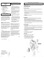
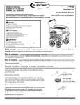
CONTROL PANEL
A.
120 V, 20 Ampere Duplex Receptacle
20 amps of current may be drawn from each half of the
receptacle. However, total power drawn must be kept within
nameplate ratings. These receptacles may be used along with
the twistlock receptacle provided the generator is not
overloaded.
B.
120/240 V, 30 Ampere Twistlock Receptacle
A maximum of 30 amps may be drawn from the 120/240 volt
receptacle, provided it is the only receptacle used.
However, current must be limited to the nameplate rating. If the
120/240 volt receptacle is used along with the 120 volt
receptacle, the total load drawn must not exceed the nameplate
ratings.
C.
Circuit Breakers
The receptacles are protected by an AC circuit breaker. If
the generator is overloaded or an external short circuit occurs,
the circuit breaker will trip. If this occurs, disconnect all
electrical loads and try to determine the cause of the problem
before attempting to use the generator again. If overloading
causes the circuit breaker to trip, reduce the load. NOTE:
Continuous tripping of the circuit breaker may cause
damage to generator or equipment. The circuit breaker may
be reset by pushing the button of the breaker.
D.
Not Covered:
Transportation charges for sending the product to the
Company or its authorized service representative for
warranty service, or for shipping repaired or replacement
products back to the customer; these charges must be
borne by the customer.
Engine is covered exclusively by a separate warranty from
the engine manufacturer, included with the engine Manual.
The engine manufacturer's warranty period is two (2) years
in the United States and one (1) year in Mexico. Damages
caused by abuse or accident, and the effects of corrosion,
erosion and normal wear and tear.
Note B: These are standard parts available at your local hardware store.
.
AWARNING: To avoid possible personal injury or equipment damage, a registered electrician or an authorized service representative shoul d
perf orm i ns t al lati on and al l s erv i ce. U nder no c irc ums t anc es s houl d an unquali fi ed person at t em pt to wi re i nto a uti li ty c i rc uit. WARNING
AVERTISSEIAENT
Warranty is voided if the customer fails to install, maintain
and operate the product in accordance with the instructions
and recommendations of the Company set forth in the
owner's manual, or if the product is used as rental
equipment.
The Company will not pay for repairs or adjustments to the
product, or for any costs or labor, performed without the
Company's prior authorization.
Warranty Period: Two(2) years from the date of purchase on
products used solely for consumer applications; if a product is
used for business or commercial applications, the warranty
period will be limited to one (1) year from the date of purchase.
For warranty service, the customer must provide dated proof of
purchase and must notify the Company within the warranty
period.
For warranty service: Call toll free 800-336-2979
Engine On/Off Switch
EXCLUSIONS AND LIMITATIONS: THE COMPANY MAKES
NO OTHER WARRANTY OF ANY KIND, EXPRESS OR
IMPLIED. IMPLIED WARRANTIES, INCLUDING
WARRANTIES OF MERCHANTABILITY AND OF FITNESS
FOR A PARTICULAR PURPOSE, ARE HEREBY
DISCLAIMED. THE WARRANTY SERVICE DESCRIBED
ABOVE IS THE EXCLUSIVE REMEDY UNDER THIS
WARRANTY; LIABILITY FOR INCIDENTAL AND
CONSEQUENTIAL DAMAGES IS EXCLUDED TO THE
EXTENT PERMITTED BY LAW.
This warranty gives you specific legal rights, and you may also
have other rights which vary from state to state. Some states
do not allow a disclaimer of implied warranties, or the exclusion
or limitation of incidental and consequential damages, so the
above disclaimers and exclusions may not apply to you.
A.
TM
CordKeeper Restraint
TM
The CordKeeper
restraint is a
unique feature used to prevent plugs
from being pulled out of the receptacles.
2
English
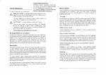
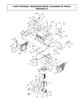
PARTS DRAWING I SCHEMA DES PIECES / DIAGRAMA DE PIEZAS
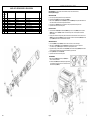
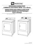
PORTABILITY KIT INSTALLATION
PARTS LIST I LISTE DES PIECES I LISTA DE PIEZAS
DESCRIPTION
DESCRIPTION
DESCRIPCION
QTY
REF PART
NO. NO.
55 1130634480
56 0035857
57 0069066
58 0051101
59 0050859
60 0069315
60A 0069330
60B 0069331
60C 0069332
61 Note B
Fuel hose 1/4 ID
Clamp, hose
Connector, hose
Clamp, hose
Clamp, hose
Generator head, Shenfa
Brush module
AVR module
Cover, end
Washer, flat 8.6mm x 30mm
Flexible de carburant
Crampon, tuyau
Connecteur de flexible
Crampon, tuyau
Crampon, tuyau
Tete de la gOneratrice, Shenfa
Brosser le module
La tension automatiquc regulatrice
Couvercle
Rondelle plates 8.6mm x 30mm
Manguera de combustible
Abrazadera, manguera
Conector de manguera
Abrazadera, manguera
Abrazadera, manguera
Cabezal del generador, Shenfa
Cepille modulo
El regulador automatic° del voltaje
Tapa
Arandela, plana 8.6mm x 30mm
1
1
1
1
1
1
1
1
1
1
TOOLS REQUIRED: 7/16", 1/2" and 9/16" sockets and ratchets, block(s) of wood (minimum of 6" tall).
Refer to the parts list on page 9.
WHEEL INSTALLATION
1. Block up end of generator opposite the fuel tank cap to install wheel kit.
2. Insert wheel spacer (item 39) into the center of the wheel (item 28).
3. Slide 3/8 x 4.25" bolt (item 32) and 3/8 washer (item 27) through the wheel (item 28), then through the wheel bracket on the
carrier, with the offset side of the wheel hub against the wheel bracket.
4. Thread 3/8 nyloc nut (item 33) onto the bolt and tighten to securely clamp the wheel assembly to the carrier.
5. Repeat above instructions for the remaining wheel.
FOOT INSTALLATION
1. Assemble the rubber feet (item 29) to the foot bracket (item 43) using a 1/4-20 x 1.5" bolt (item 11). Thread a 1/4 washer
(item 36) and a 1/4 nyloc nut (item 10) to the bolt to secure the assembly. Caution: Do not over tighten so that the foot
material collapses.
2. Blocking up the alternator side of the generator, place the foot bracket under the carrier channel. Thread a 5/16-18 x 1" bolt
(item 42) with a 5/16 wide washer (item 50) through the mounting holes and thread a 5/16 wide washer (item 50) and a 5/16
nyloc nut (item 13) to the bolt to secure the foot bracket to the carrier.
HANDLE INSTALLATION
1. Place handle (item 25) and spacer (item 46) on carrier on same end as feet, as shown in the diagram.
2. Slide 5/16 x 2.25" bolt (item 26) and 5/16 washers (item 12) through handle and spacer as shown in diagram and
secure with 5/16" nyloc nut (item 13). Tighten until handle is securely clamped to the carrier.
3. Apply aerosol hairspray or similar adhesive to the handle (item 25), and then slide the handle grip (item 40) onto the handle.
The aerosol hairspray will allow for easier assembly and will adhere the grip to the handle.
4. Insert cap (item 35) into end of handle (item 25).
5. Repeat above instructions for the remaining handle.
LOCKING HANDLE
1. Attach the lanyards (item 30) to the release pins (item 34) and
carrier as shown in the illustration.
2. To lock the handle (item 25) in the extended position, align the holes
in the handle brackets with the holes in the carrier brackets and
insert the release pins (item 34).
10
English
3
Moteur 390 cc Honda OHV
Chemise de cylindres en fonte
Detecteur de bas niveau d'huile
Prises sur tableau de cornmande
CordKeeperTM
La tension automatique regulatrice
Reservoir de carburant en metal d'une contenance
de 30.3 litres (8 gallons)
Kit de transport
A.
Prise double de 120 V, 20 A
20 amperes de courant peuvent 'ate dessinas de chaque
moiti6 de la prise. La charge totale doit cependant rester dans
les limites indiquaes sur la plaque signalatique. Ces prises
peuvent s'utiliser en conjonction avec la prise a verrouillage
condition que le ganerateur ne soit pas surchargee.
B.
Prise a verrouillage de 120/240 V, 30 A
Cette prise de 120/240 V fournit un maximum de 30 A a
condition que ce soit la seule utilis6e. La charge totale doit par
ailleurs rester dans les limites indiquaes sur la plaque
signalátique. Si la prise de 120/240 V est utilisee en
conjonction avec les prises de 120 V, la charge totale ne dolt
pas d6passer les limites indiquaes sur la plaque.
C.
Disjoncteurs
Les prises sont protegees par un disjoncteur alternatif. En
cas de surcharge ou de court-circuit extórieur, le disjoncteur
saute. Si cela se produit, clabrancher tout appareil relic au
groupe electrogene et essayer de determiner la cause du
probléme avant d'essayer de le rautiliser. Si le disjoncteur
sau te en raison d 'une surc har ge, r6d uire la char ge .
REMARQUE : Le groupe electrogene ou les appareils
branches dessus peuvent se trouver abimes si le
disjoncteur saute continuellement. Appuyer sur le bouton du
disjoncteur pour le r6enclencher.
D.
Commutateur On/Off (Sur/De) du moteur
B
A
0 01
NI
0
a
Ai r h
6a xil
J0\ai0
e
A 1411
(
4mi
4
E.
TM
CordKeeper la Restriction
Le CordKeeperTM la restriction est un
dispositif unique qui empeche la fiche de
ressortir accidentellement d'une prise.
;\ ‘
t
-#
ll
bi
e
CARACTERISTIQUES PRINCIPALES DU
GROUPE
Periode couverte par la garantie : Trois (3) ans a partir de la date
ELECTROGENE
d'achat sur les produits utilises uniquement pour les applications de
consommateur. Si le produit est utilise a des fins d'affaires ou
commerciales, la periode couverte par la garantie se limite A un (1)
an a partir de la date d'achat. En ce qui concerne l'entretien
couvert par la garantie, le client dolt presenter une preuve de la date
d'achat et it dolt aviser la compagnie au cours de la p6riode couverte par
la garantie.
EXCLUSIONS ET LIMITATIONS: LA COMPAGNIE NE PRESENTE
AUCUNE AUTRE GARANTIE, EXPRESSE OU IMPLICITE. LES
GARANTIES IMPLICITES, INCLUANT LES GARANTIES DE
QUALITE MARCHANDE ET DE CONFORMITE AUX BESOINS
SONT, PAR LA PRESENTE, ABANDONNEES. L'ENTRETIEN
COUVERT PAR LA GARANTIE DECRIT CIDESSUS EST UN
RECOURS EXCLUSIF EN VERTU DE CETTE GARANTIE. LA
RESPONSABILITE POUR DES DOMMAGES ACCESSOIRES ET
INDIRECTS EST EXCLUE JUSQU'A LA LIMITE AURORISEE PAR LA
LOI.
Cette garantie vous donne des droits specifiques reconnus par la loi.
Vous pouvez egalement b6n6ficier de certains autres droits, lesquels
varient dune province (Etat) a l'autre. Certaines provinces (ou
certains Etats) n'autorisent pas de clauses de renonciation des garanties
implicites ou de limites a l'6gard de dommages accessoires ou indirects,
ainsi, les clauses de renonciation et les exclusions ci-dessus peuvent ne
pas s'appliquer a vous.
Francais
TABLEAU DE
COMMANDE
GARANTIE
LIMITEE
REF. PART
NO. NO.
1
2
3
4
5
6
7
8
9
10
11
12
13
14
15
16
17
17A
17B
18
19
19A
19B
20
21
22
22A
22B
22C
22D
22E
22F
22G
22H
221
22J
23
24
25
26
27
28
29
30
32
33
34
35
36
37
38
39
40
41
42
43
44
45
46
47
48
49
50
51
52
53
54
0069044
Note A
0051094
0000901.01
0057512
0062797
0066645
Note B
0008854
0040832
Note B
Note B
0048736
0049224
Note B
Note B
0069445
0038984
0001537
0061392
0065546
0049071
0049382
0062020
0069062
Note C
0061877
0065450
0061817
0061942
0066076
0066072
0065809
0066090
0067767
0065127
0055982.01
Note B
0063191
Note B
Note B
0063771
0055894
0062174
Note B
0057578
0062502
0058955
Note B
0061393
0050298
0062433
0062495
0049352
Note B
0062301
0069048
0069066
0063164
0057254
Note B
Note B
Note B
1130660180
1130688810
0064138
0067624
PARTS LIST I LISTE DES PIECES I LISTA DE PIEZAS
DESCRIPTION
DESCRIPTION
DESCRIPCION
Carrier, assembly
Engine 13 hp Honda OHV
Isolator
Bolt whz 5/16-24 x .63
Bolt whz 3/8-18 x 1 1/4
Connector, panel
Bolt, hex 5/16-24 x 9.65
Washer, lock 5/16
Lug, ground
Nut, nyloc 1/4-20
Bolt, 5/16-18 x 1 1/2
Washer, flat 5/16
Nut, nyloc 5/16-18
Assembly, ground wire
Washer, star external 5/16
Bolt, hex 5/16-18 x 3/4
Muffler
Screen, spark arrest
Screw #8-32 x 3/8
Gasket
Panel, wired
Circuit Breaker 20 amp
Circuit Breaker 30 amp
Screw #6-19 x .50 Torx
Shield, heat
Fuel tank assembly
Grommet
Fuel Cap
Fuel gauge/screws
Fuel filter
Decal, fuel gauge
Insert mount
Fuel shut off
Ring, chain attachment
Valve, rollover
Bushing, valve
Cord Keeper"
Bolt, 1/4-20 x 1
Handle
Bolt, 5/16-18 x 2 1/4
Washer, flat 3/8
Wheel
Rubber Foot
Lanyard
Bolt, 3/8-16 x 4.25
Nut, nyloc 3/8-16
Pin, release
Cap, plastic
Washer, flat 1/4
Nut whz 8mm
Switch, Rocker
Wheel spacer
Grip, handle
Washer, flat 5/16 W
Bolt, 5/16-18 x 1
Bracket, foot
Cap, vinyl dip
Connector, hose
Spacer, handle bracket
Nut, hex fig 5/16-18
Bolt, 5/16-18 x 1 1/4
Washer, star external 1/4
Bolt, 1/4-20 x 1 1/2
Fuel hose 4.5mm ID
Fuel hose 8mm ID
Screw #10 x 3/4
Clip, adhesive mount
Ensemble transport
Moteur
Sectionneur
Boulon
Boulon
Conneetcur, tableau
Boulon
Contre-ecrou 5/16
Oeillet de mise a la terre
Ecrous nyloc 1/4-20
Boulon
Rondelle plates 5/16
Ecrous nyloc 5/16-18
Ensemble fil de masse tresse a tierra
Rondelle a dents externa 5/16
Boulon, tete hex 5/16-18 x 3/4
Silencicux
Crepine, pare-dtincelles
Vis
Joint
Tableau complet cable
Disjoncteurs 20 amp
Disjoncteurs 30 amp
Vis
Ecran de chaleur
Ensemble complet du reservoir
Oeillet
Capuchon
Jauge de carburant/v s
Filtre a carburant
Decalcomanie de jauge
Insertion
Robinet de carburant
Anneau
Soupape
Bague
Cord KeeperTM
Boulon
Poignde
Boulon
Rondelle plates 3/8
Roue
Pied
Lanyard
Boulon
Ecrous nyloc 3/8-16
Epingle de relachement
Capuchon
Rondelle plates 1/4
Ecrous
Interrupteur
Bague d'espacement
Poignee
Rondelle plates 5/16 large
Boulon
Support de pied
Capuchon
Connecteur de flexible
Entretoise
Ecrous 5/16-18
Boulon
Rondelle a dents externa 1/4
Boulon
Flexible de carburant
Flexible de carburant
Vis
Attache
Transportador, conjunto
Motor
Aislador
Perno
Perno
Conector, panel
Perno
Arandela, de cierre 5/16 (7,94 mm)
Terminal, tierra
Tuerca, nyloc 1/4-20 (6,35 mm)
Perno
Arandela, plana 5/16 (7,94 mm)
Tuerca, nyloc 5/16-18 (7,94 mm)
Conjunto, cable trenzado
Arandela, estrella
Perno
Silenciador
Malla, apagachispas
Tomillo
Empaquetadura
Panel, cabeado completo
Cortacircuitos 20 A
Cortacircuitos 30 A
Tomillo
Pantalla para el calor
Conjunto tanque
Arandela de cabo
Tapa de combustible
Indicador de combustible/tornillos
Filtro de combustible
Calcomania de indicador
Inserto
Valvula combustible
Anillo
Valvula
Buie
Cord Keeper'
Perno
Manija
Perno
Arandela, plana 3/8 (9,53 mm)
Rucda
Pic
Acollador
Perno
Tuerca, nyloc 3/8-16 (9,53 mm)
Alfileres de la liberation
Tapa
Arandela, plana 1/4 (6,35 mm)
Tuerca
Interruptor
Espaciador de la rueda
Empufladura
Arandela, plana 5/16 (7,94 mm) de largo
Perno
Soporte del pie
Tapa
Conector de manguera
Espaciador
Tuerca 5/16-18 (7,94 mm)
Pemo
Arandela, estrella
Pemo
Manguera de combustible
Manguera de combustible
Tornillo
Presilla
QTY
1
1
4
2
4
I
1
4
1
6
2
4
4
1
2
1
1
1
4
1
1
2
2
4
1
1
4
I
1
1
1
4
1
1
1
1
2
4
2
2
2
2
2
2
2
2
2
2
10
2
1
2
2
4
2
i
1
1
2
5
2
1
2
I
1
2
2
9
8
L'INSTALLATION DE KIT DE TRANSPORT
OUTILS NECESSAIRES : Cliquet a rochet de 7/16 po, 1/2 po, et 9/16 po, blocs de bois (minimum de 6 po de hauteur)
Reportez-vous a la liste des pieces des page 9.
INSTALLATION DES ROUES
1. Faire reposer l'extrAmita de la gAnAratrice a l'opposê de celle ou se trouve le capuchon du reservoir d'essence sur un bloc de
fawn a pouvoir effectuer la pose de la roue.
2. Insèrer une bague d'espacement (article 39) dans le centre de la roue (article 28).
3. Enfiler le boulon de 3/8 x 4.25 po (article 32) et rondelle de 3/8 po (article 27) dans la roue (article 28), puis dans le support
de la roue sur le transporteur, en le plagant de fawn a ce que le cote le plus en creux du moyeu de la roue repose contre le
support.
4. Enfiler l'Acrou a frein elastique de 3/8 po (article 33) sur le boulon et serrer de fagon a bien fixer la roue sur la transporteur.
5. ProcAder de la nnAnne fawn pour I'autre roue.
INSTALLATION DU PIED
1. Monter le pied (article 29) sur le support de pied (article 43) au moyen d'un boulon de 1/4-20 x 1.5 po (article 11). Fixer
['ensemble en vissant sur le boulon un Acrou nyloc (article 10), avec une rondelle (article 36). Attention: ne pas trop serrer,
pour ne pas Acraser le matAriau du pied.
2. En bloquant le cote alternateur de la generatrice, mettre en place le support de pied sous le profile en U. Visser un boulon de
5/16-18 x 1 po (article 42) avec une rondelle de 5/16 po large (article 50) dans les trous de fixation, puis visser sur le boulon
un Acrou nyloc de 5/16 po (article 13), avec une rondelle de 5/16 po large (article 50) pour fixer le support de pied au profile.
POSE DE LA POIGNEE
1. Mettre la poignee (article 25) et entretoise (article 46) sur la chariot du cote 00 se trouvent les pieds tel qu'indique sur le
diagramme.
2. Insêrer le boulon de 5/16 x 2.25 po (article 26) et rondelles de 5/16 po (article 12) dans la poignee et entretoise tel qu'indiqub
sur le diagramme et fixer en place a ['aide de l'ècrou a frein elastique de 5/16 po (article 13). Serrer jusqu'a ce que la poignee
soit bien fixAe sur la chariot.
3. Appliquez un aerosol de laque ou un produit adhAsif semblable sur la poignee (article 25) et faites ensuite glisser la prise
(article 40) sur la poignee. L'emploi de ('aerosol de laque en facilitera ('assemblage et permettra a la prise de coller a la
poignee.
4. L'insertion capuchon (article 35) dans les fin de poignee (article 25).
5. Procèder de la mAme fagon pour I'autre poignee.
POIGNEE VERROUILLANT
1. Attacher le lanyards (article 30) aux Apingles de relächement (article
34) et le transporteur selon ('illustration.
2. Pour verrouiller la poignee (article 25) dans la position Atendue,
aligner les trous dans les support de poignee avec les trous dans les
support de transporteur et insArer les Apingles de relächement
(article 34).
Frangais
5
3
Motor 390 cm Honda OHV
Manga de hierro fundido del cilindro
El sensor del nivel bajo de aceite
Receptâculos sobre el panel de control
CordKeeperTM
El regulador automatic° del voltaje
Tanque de metal de combustible con capacidad
de 30.3 litros (8 galones)
Juego de transporte
PANEL DE CONTROL
Receptaculo duplex de 120 volts, 20 amperes
20 amperes de la corriente se pueden dibujar de calla
mitad del receptaculo. Sin embargo, la potencia total extraida
debe mantenerse dentro de los valores nominales de la place
de identificaciOn. Estos receptâculos pueden usarse junto con el
receptaculo de cierre giratorio siempre y cuando el
generador no este sobrecargado.
No estan cubiertos:
Costos de transporte por el envio del producto a la
Campania o a sus representantes de servicio autorizados
por servicio de garantias, o por el reenvio de los productos
reparados o de reemplazo al consumidor; estos cargos los
debere cubrir el cliente.
El motor este cubierto exclusivamente por una garantia por
separado por parte del fabricante del motor, que se incluye
en el Manual del motor. El periodo de la garantia del
fabricante del motor es tres (3) anos en Estados
Unidos y uno (1) ano en Mexico.
A.
B. Receptâculo de cierre giratorio de 120/240 volts, 30
amperes
Puede extraerse un meximo de 30 A desde el receptaculo
de 120/240 volts siempre y cuando sea el Onico receptaculo
usado. Sin embargo, la corriente debe limitarse al valor
nominal de la place de identificaci6n. Si se utiliza un
receptaculo de 120/240 volts junto con los receptaculos de 120
volts, la carga total extraida no debe exceder los valores
nominales de la place de identificaciOn.
C.
Interruptor
Los recepteculos se protegen mediante un cortacircuitos de
CA. Si se sobrecarga el generador u ocurre un cortocircuito
externo, el cortacircuitos saltarà. Si esto ocurre, desconecte
todas las cargas electricas y trate de determinar la causa del
problema antes de usar el generador nuevamente. Si la
sobrecarga causa que salte el cortacircuitos, reduzca la carga.
NOTA: Si salta continuamente el cortacircuitos, se podria
danar el generador o el equipo. El cortacircuitos puede
restaurarse pulsando el botOn del cortacircuitos.
D.
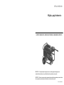
INSTALACION DEL JUEGO DE TRANSPORT
GARANTIA LIMITADA
CARACTERISTICAS PRINCIPALES DEL
GENERADOR
Davos ocasionados por el mal uso o por un accidente, y los
efectos de la corrosion, la erosion, el desgaste y el uso
normales.
La garantia no sera valida si el consumidor no instala,
da mantenimiento y hace funcionar el producto de acuerdo
con las instrucciones y recomendaciones de la Compania,
descritas en el manual del usuario, o si el producto se
utiliza como equipo de arrendamiento.
La Compania no pagare por reparaciones ni ajustes al
producto, ni costos ni mano de obra, realizado sin la
Compania's la autorizaciOn previa.
Periodo de garantia: Tres (3) arias de la fecha de la compra
en productos utilizados Onicamente para aplicaciones de
consumo; si un producto se utiliza para usos comerciales o con
y
fines de lucro, el periodo de garantia se limitar a un (1) alio a
partir de la fecha de compra. Para obtener el servicio de
garantia, el cliente debe proporcionar el comprobante de
compra fechado y debe notificar a la Campania dentro del
periodo de garantia.
Esta garantia le otorga derechos legales especificos y tambien
puede ser objeto de otros derechos que varian de estado a
estado. Algunos Estados no permiten la exenciOn de
responsabilidad de garantias implicitas o la exclusion o
linnitaciOn de alarms incidentales o consecuentes, de manera
que las exenciones y exclusiones de responsabilidades pueden
no ser aplicables a usted.
Espanol
HERRAMIENTAS NECESARIAS: Cubos y trinquetes de 7/16" (11,11 mm), 1/2" (12,70 mm) y 9/16" (14,29 mm), bloque(s) de
madera, minima de 6" (15,25 cm) de alto.
Consulte la lista de partes en las pagina 9.
INSTALACION DE LAS RUEDAS
1. Bloquee el extremo del generador situado en el lado opuesto a la tapa del tanque de combustible para instalar el juego de
rueda.
2. Inserte el espaciador de la rueda (articulo 39) en el centro de la rueda (articulo 28).
3. Deslice el perno de 3/8 X 4.25" (9,53 mm x 10,80 cm) (articulo 32) y arandela de 3/8 (9,53 mm) (articulo 27) a traves de la
rueda (articulo 28), y luego a traves del soporte de la rueda en el transportador, colocando el lado descentrado del centro de
la rueda en contra del soporte.
4. Atornille la tuerca de nyloc de 3/8 (9,53 mm) (articulo 33) en el perno y aprietela para fijar firmemente el conjunto de la rueda
a la transportador.
5. Repita el procedimiento anterior para la otra rueda.
INSTALACION DEL PIE
1. Ensemble la pie (articulo 29) al soporte de la misma (articulo 43) con un perno de 1/4-20 x 1.5" (6,35 mm x 3,81 cm)
(articulo 11). Enrosque una arandela (articulo 36) y una tuerca nyloc (articulo 13) al perno para asegurar el ensamble.
Precauci6n: No apriete demasiado para que el material de la pie no colapse.
2. Bloquee el lado del alternador del generador para colocar el soporte de la pie bajo el canal portador. Enrosque un perno de
5/16-18 x 1" (7,94 mm x 2,54 cm) (articulo 42) con una arandela de 5/16 (7,94 mm) lejos (articulo 50) a traves de los orificios
de montaje y enrosque una arandela de 5/16 (7,94 mm) lejos (articulo 50) y una tuerca nyloc de 5/16 (7,94 mm) (articulo 13) al
perno para asegurar el soporte de la pie al portador.
INSTALACION DE LA MANIJA
1. Coloque la manija (articulo 25) y espaciador (articulo 46) sobre la transportadora en el mismo extremo de las patas, tal como
se indica en el diagrama.
2. Deslice el perno de 5/16 x 2.25" (7,94 mm x 5,72 cm) (articulo 26) y arandela de 5/16 (7,94 mm) (articulo 12) a traves de la
manija y espaciador, tal como se indica en el diagrama, y fijela con la tuerca de nyloc de 5/16 (7,94 mm) (articulo 13). Aprietela
hasta que la manija quede firmemente asegurada a la transportadora.
3. Aplique rociador para el cabello en aerosol o un adhesivo similar a la manija (articulo 25), y luego deslice el agarradero de la
manija (articulo 40) sobre la manija. El rociador para el cabello en aerosol permitira un ensamble mas fàcil y adherire el
agarradero a la manija.
4. La adiciOn tapa (articulo 35) en fines del manija (articulo 25).
5. Repita el procedimiento anterior para la otra manija.
MANIJA QUE CIERRA
1. Conecte los acoladores (articulo 30) a los alfileres de la liberaciOn
(articulo 34) y el portador como mostrado en la ilustraciOn.
2. Para cerrar el manija (articulo 25) en la posiciOn extendida, alinea los
hoyos en los soporte del manija con los hoyos en los soporte de
transportador y mete los alfileres de la liberaciOn (articulo 34).
El motor On/Off (En/De) Interruptor
B
A
e
.
e
ESTA ARANDELA VA ENTRE
MANIJA Y FUERA DE PORTADOR
0 ,, 0
Q„,
ee
-:
0
.....
D -E
E.
TM
CordKeeper RestricciOn
TM
El CordKeeper
restricci6n es una
caracteristica exclusive que se utiliza para
impedir que los tapones se salgan de los
recepteculos de 120 volts.
6
Espanol
7