1
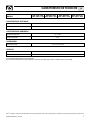
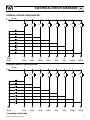
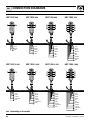
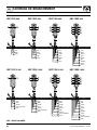
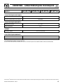
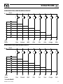
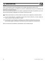
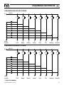
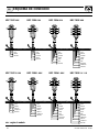
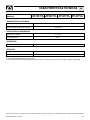
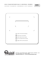
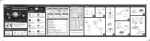
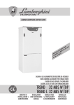
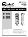
REV 003A
INTEGRATIVO
SUPPLEMENTARY
COMPLÉMENTAIRE
ZUSATZ
INTEGRATIVO
High Quality Nautical Equipment
PULSANTIERA MULTIUSO
HRC 1002 C05
HRC 1004 C02
HRC 1006 C01
HRC 1006 C03
HRC 1008 C01
IT
Manuale d'uso
PULSANTIERA MULTIUSO HRC
GB
User's Manual
HRC MULTIPURPOSE CONTROL PANEL
FR
Manuel de l'utilisateur
BOITIER DE COMMANDE MULTI-USAGE HRC
DE
Benutzerhandbuch
MEHRZWECK-FERNBEDIENUNG HRC
ES
Manual del usuario
TABLERO DE PULSADORES MULTIUSO HRC
IT
Pag.
Pag.
Pag.
Pag.
GB
Pag.
Pag.
Pag.
Pag.
FR
INDICE
4
5
6
7
INDEX
4
5
6
7
Pág.
Pág.
Pág.
Pág.
Description
Schémas électriques des boîtiers de commande
Schémas de branchement des boîtiers de commande
Caractéristiques techniques
INHALTSANGABE
Seite 4
Seite 5
Seite 6
Seite 19
ES
Description
Control panel circuit diagrams
Control panel connection diagrams
Technical data
SOMMAIRE
Pag. 4
Pag. 5
Pag. 6
Pag. 15
DE
Descrizione
Schemi elettrici pulsantiere
Schemi di collegamento pulsantiere
Caratteristiche tecniche
Beschreibung
Schaltpläne Fernbedienung
Anschlusspläne Fernbedienung
Technische daten
INDICE
28
29
30
31
Descripción
Esquema eléctricos tablero de pulsadores
Esquema de conexión tablero de pulsadores
Caracteristicas tecnicas
HRC100X-INTEGRATIVO - REV03A
3
IT
DESCRIZIONE
Questo e' un manuale d'uso integrativo per le pulsantiere HRC.
Queste pulsantiere sono dotate di una funzione supplementare utile all'azionamento di dispositivi a
comando idraulico.
Questo è reso possibile disponendo di un collegamento supplementare della pulsantiera cui fa capo un
circuito a diodi in configurazione a catodo o anodo comune.
Le pulsantiere a diodi possono essere utilizzate solo con segnali in corrente continua.
caso di discordanze o eventuali errori tra il testo tradotto e quello originario in italiano, fare riferiF Inmento
al testo italiano o inglese.
dispositivo è stato progettato e realizzato per essere utilizzato su imbarcazioni da diporto.
F Questo
Non è consentito un utilizzo differente senza autorizzazione scritta da parte della società Quick .
®
Per le istruzioni di installazione e funzionamento si rimanda al manuale principale.
4
HRC100X-INTEGRATIVO - REV03A
SCHEMI ELETTRICI
IT
CONFIGURAZIONE CATODO COMUNE*
C
Marrone
Comune
1
Diodo
Rosa
1
Blu
2
2
Nero
3
3
Bianco
4
5
6
4
Verde
5
Rosso
6
Grigio
4
5
6
4
Verde
5
Rosso
6
Grigio
7
7
Arancio
8
8
Giallo
CONFIGURAZIONE ANODO COMUNE*
C
Marrone
Comune
1
Diodo
Rosa
1
Blu
2
2
Nero
3
3
Bianco
7
7
Arancio
8
8
Giallo
* A seconda dei modelli
HRC100X-INTEGRATIVO - REV03A
5
IT
SCHEMI DI COLLEGAMENTO
HRC 1002 xxx
1
HRC 1004 xxx
2
HRC 1006 xxx
HRC 1008 xxx
1
2
1
2
1
2
3
4
3
4
3
4
5
6
5
6
7
8
MARRONE COMUNE
MARRONE COMUNE
MARRONE COMUNE
MARRONE COMUNE
1
BLU
1
BLU
1
BLU
1
BLU
2
NERO
2
NERO
2
NERO
2
NERO
D
ROSA
3
BIANCO
3
BIANCO
3
BIANCO
4
VERDE
4
VERDE
4
VERDE
D
ROSA
5
ROSSO
5
ROSSO
6
GRIGIO
6
GRIGIO
D
ROSA
7
ARANCIO
8
GIALLO
D
ROSA
HRC 1002 L xxx
1
HRC 1004 L xxx
2
HRC 1006 L xxx
HRC 1008 L xxx
1
2
1
2
1
2
3
4
3
4
3
4
5
6
5
6
7
8
MARRONE COMUNE
MARRONE COMUNE
MARRONE COMUNE
MARRONE COMUNE
1
BLU
1
BLU
1
BLU
1
BLU
2
NERO
2
NERO
2
NERO
2
NERO
A
VIOLA
3
BIANCO
3
BIANCO
3
BIANCO
B
TURCHESE
4
VERDE
4
VERDE
4
VERDE
D
ROSA
A
VIOLA
5
ROSSO
5
ROSSO
B
TURCHESE
6
GRIGIO
6
GRIGIO
D
ROSA
A
VIOLA
7
ARANCIO
B
TURCHESE
8
GIALLO
D
ROSA
A
VIOLA
B
TURCHESE
D
ROSA
xxx : secondo il modello.
6
HRC100X-INTEGRATIVO - REV03A
CARATTERISTICHE TECNICHE
HRC 1002 XXX
HRC1004 XXX
HRC 1002 L XXX HRC 1004 L XXX
MODELLI
HRC 1006 XXX
HRC 1006 L XXX
IT
HRC 1008 XXX
HRC 1008 L XXX
CARATTERISTICHE ELETTRICHE
Portata in corrente dei contatti (1)
Tensione di commutazione sui contatti
2,5A
30 Vdc Max
CARATTERISTICHE AMBIENTALI
Temperatura operativa
Grado di protezione
(2)
-15 ÷ +70 °C
IP 67
CONTENITORE
Dimensioni (LxAxP)
62.2 x 185 x 49.4 mm
GENERALI
Massima estensione cavo
Classe EMC
4.2 m
EN 55022/B
(1) In funzionamento continuo su carico resistivo.
(2) Con la spina correttamente inserita nella presa. Esclusa la zona della presa dove è saldato il cavo di uscita (IP 00).
QUICK® SI RISERVA IL DIRITTO DI APPORTARE MODIFICHE ALLE CARATTERISTICHE TECNICHE DELL'APPARECCHIO E AL CONTENUTO DI QUESTO MANUALE SENZA ALCUN PREAVVISO.
HRC100X-INTEGRATIVO - REV03A
7
GB
DESCRIPTION
This is a supplementary user's manual for the HRC control panels.
These control panels have a supplementary function that is useful for activating hydraulic control
devices. This is made possible with an additional connection to the control panel, governed by a diode
circuit configured with a common anode or cathode.
The diode control panel can only be used with DC signals.
case of discordance or errors in translation between the translated version and the original text
F Inin the
Italian language, reference will be made to the Italian or English text.
device was designed and constructed for use on recreational crafts.
F This
Other forms of use are not permitted without written authorization from the company Quick .
®
For the installation and operating instructions see the main manual.
8
HRC100X-SUPPLEMENTARY - REV03A
ELECTRICAL CIRCUIT DIAGRAMS
GB
COMMON CATHODE CONFIGURATION*
C
Brown
Round
Pink
diode
1
2
3
4
5
6
1
Blue
2
Black
3
White
4
Green
5
Red
6
Grey
7
7
Orange
8
8
Yellow
COMMON ANODE CONFIGURATION*
C
Pink
diode
Brown
Round
1
2
3
4
5
6
1
Blue
2
Black
3
White
4
Green
5
Red
6
Grey
7
7
Orange
8
8
Yellow
* Depending on the mode
HRC100X-SUPPLEMENTARY - REV03A
9
GB
CONNECTION DIAGRAMS
HRC 1002 xxx
1
2
HRC 1004 xxx
HRC 1006 xxx
HRC 1008 xxx
1
2
1
2
1
2
3
4
3
4
3
4
5
6
5
6
7
8
BROWN ROUND
BROWN ROUND
BROWN ROUND
BROWN ROUND
1
BLUE
1
BLUE
1
BLUE
1
BLUE
2
BLACK
2
BLACK
2
BLACK
2
BLACK
D
PINK
3
WHITE
3
WHITE
3
WHITE
4
GREEN
4
GREEN
4
GREEN
D
PINK
5
RED
5
RED
6
GREY
6
GREY
D
PINK
7
ORANGE
8
YELLOW
D
PINK
HRC 1002 L xxx
1
2
HRC 1004 L xxx
HRC 1006 L xxx
HRC 1008 L xxx
1
2
1
2
1
2
3
4
3
4
3
4
5
6
5
6
7
8
BROWN ROUND
BROWN ROUND
BROWN ROUND
BROWN ROUND
1
BLUE
1
BLUE
1
BLUE
1
BLUE
2
BLACK
2
BLACK
2
BLACK
2
BLACK
A
PURPLE
3
WHITE
3
WHITE
3
WHITE
B
TURQUOISE
4
GREEN
4
GREEN
4
GREEN
D
PINK
A
PURPLE
5
RED
5
RED
B
TURQUOISE
6
GREY
6
GREY
D
PINK
A
PURPLE
7
ORANGE
B
TURQUOISE
8
YELLOW
D
PINK
A
PURPLE
B
TURQUOISE
D
PINK
xxx : depending on the mode
10
HRC100X-SUPPLEMENTARY - REV03A
TECHNICAL DATA
HRC 1002 XXX
HRC1004 XXX
HRC 1002 L XXX HRC 1004 L XXX
MODELS
HRC 1006 XXX
HRC 1006 L XXX
GB
HRC 1008 XXX
HRC 1008 L XXX
ELECTRICAL CHARACTERISTICS
Current capacity of contacts (1)
Switching voltage on the contact
2,5A
30 Vdc Max
AMBIENT CHARACTERISTICS
Operating temperature
Protection rating
(2)
-15 ÷ +70 °C
IP 67
CASE
Dimensions (LxHxD)
62.2 x 185 x 49.4 mm
GENERAL
Maximum cable extension
EMC class
4.2 m
EN 55022/B
(1) Continuous operation with resistive load.
(2) With the plug correctly inserted into the socket. Excluding the area of the socket where the exit cable is fixed (IP 00).
QUICK® RESERVES THE RIGHT TO MODIFY THE TECHNICAL CHARACTERISTICS OF THE EQUIPMENT AND THE CONTENTS OF THIS MANUAL WITHOUT PRIOR NOTICE.
HRC100X-SUPPLEMENTARY - REV03A
11
FR
DESCRIPTION
Ceci est un manuel d'utilisation complémentaire pour les boîtiers de commande HRC.
Ces boîtiers de commande sont munis d'une fonction supplémentaire utile pour actionner les
systèmes à commande hydraulique. Ceci est réalisable grâce à l'utilisation d'un point de raccordement
supplémentaire,munies de diodes, avec configuration à cathodes ou à anodes communes
Les boîtiers de commande à diodes ne peuvent être utilisés qu'avec des signaux à courant continu.
cas de discordances ou d’erreurs éventuelles entre la traduction et le texte original en italien, se
F Enréférer
au texte italien ou anglais.
a été conçu et réalisé pour être utilisé sur des bateaux de plaisance.
F CeToutdispositif
autre emploi est interdit sans autorisation écrite de la société Quick .
®
Pour les instructions d'installation et de fonctionnement, voir le manuel principal.
12
HRC100X-COMPLÉMENTAIRE - REV03A
SCHÉMAS ÉLECTRIQUES
FR
CONFIGURATION CATHODE COMMUNE*
C
Marron
Commun
Diode
Rose
1
2
3
4
5
6
1
Bleu
2
Noir
3
Blanc
4
Vert
5
Rouge
6
Gris
7
7
Orange
8
8
Juane
CONFIGURATION ANODE COMMUNE*
C
Marron
Commun
Diode
Rose
1
2
3
4
5
6
1
Bleu
2
Noir
3
Blanc
4
Vert
5
Rouge
6
Gris
7
7
Orange
8
8
Juane
* Selon les modèles
HRC100X-COMPLÉMENTAIRE - REV03A
13
FR
SCHÉMAS DE BRANCHEMENT
HRC 1002 xxx
1
2
HRC 1004 xxx
HRC 1006 xxx
HRC 1008 xxx
1
2
1
2
1
2
3
4
3
4
3
4
5
6
5
6
7
8
MARRON COMMUN
MARRON COMMUN
MARRON COMMUN
MARRON COMMUN
1
BLEU
1
BLEU
1
BLEU
1
BLEU
2
NOIR
2
NOIR
2
NOIR
2
NOIR
D
ROSE
3
BLANC
3
BLANC
3
BLANC
4
VERT
4
VERT
4
VERT
D
ROSE
5
ROUGE
5
ROUGE
6
GRIS
6
GRIS
D
ROSE
7
ORANGE
8
JAUNE
D
ROSE
HRC 1002 L xxx
1
2
HRC 1004 L xxx
HRC 1006 L xxx
HRC 1008 L xxx
1
2
1
2
1
2
3
4
3
4
3
4
5
6
5
6
7
8
MARRON COMMUN
MARRON COMMUN
MARRON COMMUN
MARRON COMMUN
1
BLEU
1
BLEU
1
BLEU
1
BLEU
2
NOIR
2
NOIR
2
NOIR
2
NOIR
A
MAUVE
3
BLANC
3
BLANC
3
BLANC
B
BLEU TURQUOISE
4
VERT
4
VERT
4
VERT
D
ROSE
A
MAUVE
5
ROUGE
5
ROUGE
B
BLEU TURQUOISE
6
GRIS
6
GRIS
D
ROSE
A
MAUVE
7
ORANGE
B
BLEU TURQUOISE
8
JAUNE
D
ROSE
A
MAUVE
B
BLEU TURQUOISE
D
ROSE
xxx : selon le modèle
14
HRC100X-COMPLÉMENTAIRE - REV03A
ENTRETIEN - CARACTÉRISTIQUES TECHNIQUES
HRC 1002 XXX
HRC1004 XXX
HRC 1002 L XXX HRC 1004 L XXX
MODÉLES
HRC 1006 XXX
HRC 1006 L XXX
FR
HRC 1008 XXX
HRC 1008 L XXX
CARACTÉRISTIQUES ELECTRIQUES
Charge maxi des contacts (1)
Tension de commutation sur les contacts
2,5A
30 Vdc Max
CARACTERISTIQUES AMBIANTES
Température de service
Degré de protection
(2)
-15 ÷ +70 °C
IP 67
COFFRET
Dimensions (LxHxP)
62.2 x 185 x 49.4 mm
CARACTERISTIQUES GENERALES
Extension maximum du câble
Catégorie EMC
4.2 m
EN 55022/B
(1) En fonctionnement continu sur charge résistive.
(2) Avec la fiche correctement introduite dans la prise. La zone de la prise où est soudé le câble de sortie est exclue (IP 00).
LA SOCIETÉ QUICK® SE RÉSERVE LE DROIT D’APPORTER LES MODIFICATIONS NÉCESSAIRES AUX CARACTÉRISTIQUES TECHNIQUES DE L’APPAREIL ET AU CONTENU DE CE LIVRET SANS AVIS PRÉALABLE.
HRC100X-COMPLÉMENTAIRE - REV03A
15
DE
BESCHREIBUNG
Dieses Handbuch handelt es sich um eine Ergängung des Benutzerhandbuch für die Fernbedienung HRC.
Diese Fernbedienungen sind mit einer Zusatzfunktion zur Betätigung von Vorrichtungen mit
hydraulischem Antrieb ausgestattet. Möglich ist das über einen Zusatzanschluss der Fernbedienung, der
an einen Dioden-Schaltkreis mit gemeinsamer Kathoden- oder Anodenkonfiguration angeschlossen ist.
Die Dioden-Fernbedienungen können nur mit Gleichstromsignalen verwendet werden.
Fehlern oder eventuellen Unstimmigkeiten zwischen der Übersetzung und dem Ausgangstext
F Bei
ist der Ausgangstext in Italienisch oder Englisch maßgeblich.
Vorrichtung wurde für den Einsatz auf Sportbooten entwickelt und realisiert.
F Diese
Ohne schriftliche Zustimmung durch Quick ist keine anderweitige Nutzung zulässig.
®
Nähere Informationen zur Installation und Funktionsweise können dem eigentlichen Handbuch
entnommen werden.
16
HRC100X-ZUSATZ - REV03A
SCHALTPLÄNE
DE
KONFIGURATION GEMEINSAME KATHODE*
C
Braun
Gemeinsam
1
Rosa
Diode
1
Blau
2
2
Schwarz
3
4
3
Weiß
4
Grün
5
5
Rot
6
6
Grau
7
7
Orange
8
8
Gelb
KONFIGURATION GEMEINSAME ANODE*
C
Braun
Gemeinsam
1
Rosa
Diode
1
Blau
2
2
Schwarz
3
4
3
Weiß
4
Grün
5
5
Rot
6
6
Grau
7
7
Orange
8
8
Gelb
* Je nach Modell
HRC100X-ZUSATZ - REV03A
17
DE
ANSCHLUSSPLÄNE
HRC 1002 xxx
1
2
HRC 1004 xxx
2
1
2
1
2
3
4
3
4
3
4
5
6
5
6
7
8
BRAUN GEMEINSAM
BLAU
SCHWARZ
ROSA
2
D
HRC 1008 xxx
1
BRAUN GEMEINSAM
1
HRC 1006 xxx
BRAUN GEMEINSAM
BLAU
SCHWARZ
WEIß
GRÜN
ROSA
1
2
3
4
D
BRAUN GEMEINSAM
BLAU
SCHWARZ
WEIß
GRÜN
ROT
GRAU
ROSA
1
2
3
4
5
6
D
1
2
3
4
5
6
7
8
D
HRC 1002 L xxx
1
2
HRC 1004 L xxx
2
A
B
D
BLAU
SCHWARZ
LILA
TÜRKIS
ROSA
HRC 1008 L xxx
1
2
1
2
1
2
3
4
3
4
3
4
5
6
5
6
7
8
BRAUN GEMEINSAM
1
HRC 1006 L xxx
BRAUN GEMEINSAM
1
2
3
4
A
B
D
BLAU
SCHWARZ
WEIß
GRÜN
LILA
TÜRKIS
ROSA
BRAUN GEMEINSAM
1
2
3
4
5
6
A
B
D
BLAU
SCHWARZ
WEIß
GRÜN
ROT
GRAU
LILA
TÜRKIS
ROSA
BRAUN GEMEINSAM
1
2
3
4
5
6
7
8
A
B
D
xxx : je nach Modell.
18
BLAU
SCHWARZ
WEIß
GRÜN
ROT
GRAU
ORANGE
GELB
ROSA
BLAU
SCHWARZ
WEIß
GRÜN
ROT
GRAU
ORANGE
GELB
LILA
TÜRKIS
ROSA
HRC100X-ZUSATZ - REV03A
WARTUNG - TECHNISCHE DATEN
MODELLE
HRC 1002 XXX
HRC1004 XXX
HRC 1002 L XXX HRC 1004 L XXX
HRC 1006 XXX
HRC 1006 L XXX
DE
HRC 1008 XXX
HRC 1008 L XXX
ELEKTRISCHE EIGENSCHAFTEN
Maximalstrom (1) der Kontakte
Schaltspannung an den Kontakten
2,5A
30 Vdc Max
RAUMEIGENSCHAFTEN
Betriebstemperatur
Schutzstufe (2)
-15 ÷ +70 °C
IP 67
BEHÄLTER
Abmessungen (LxBxT)
62.2 x 185 x 49.4 mm
ALLGEMEINES
Maximale Länge Kabel
EMC-Klasse
4.2 m
EN 55022/B
(1) In Dauerbetrieb bei Widerstandsbelastung.
(2) Bei korrekt in die Steckdose eingestecktem Stecker. Mit Ausnahme des Steckdosenbereichs, wo das Ausgangskabel angelötet ist (IP 00).
QUICK® BEHÄLT SICH DAS RECHT AUF ÄNDERUNGEN DER TECHNISCHEN EIGENSCHAFTEN DES GERÄTS UND DES INHALTS DIESES HANDBUCHS OHNE VORANKÜNDIGUNG VOR.
HRC100X-ZUSATZ - REV03A
19
ES
DESCRIPCIÓN
Este es un manual del usuario de completación de los tableros de pulsadores multiuso HRC.
Estos tableros de pulsadores son dotados de una función suplementaria útil para el accionamiento de
dispositivos con mandos idraulicos.
Esto se hace posible disponendo de una conexión suplementaria del tablero de pulsadores en el cual,
hay un circuito de diodos configurados con el catodo o el anodo en común.
El tablero de pulsadores con diodos pueden ser usados solo con segnales en corriente continua.
caso de discordancias o eventuales errores entre el texto traducido y el texto original en
F Enitaliano,
remitirse al texto en italiano o en inglés.
dispositivo ha sido diseñado y realizado para ser utilizado en embarcaciones de recreo.
F Este
No se permite ningún uso diferente sin autorización escrita por parte de la sociedad Quick .
®
Para las instrucciones de instalación y funcionamiento, ver el manual principal.
20
HRC100X-INTEGRATIVO - REV03A
ESQUEMAS ELÉCTRICOS
ES
CONFIGURACIÓN CATODO COMÚN*
C
Marrón
Común
Diodo
Rosado
1
2
1
Azul
2
Negro
3
3
Blanco
4
5
6
4
Verde
5
Rojo
6
Gris
4
5
6
4
Verde
5
Rojo
6
Gris
7
7
Naranjo
8
8
Amarillo
CONFIGURACIÓN ANODO COMÚN*
C
Marrón
Común
Diodo
Rosado
1
2
1
Azul
2
Negro
3
3
Blanco
7
7
Naranjo
8
8
Amarillo
* Según los modelos
HRC100X-INTEGRATIVO - REV03A
21
ESQUEMA DE CONEXIÓN
ES
HRC 1002 xxx
1
2
HRC 1004 xxx
HRC 1008 xxx
1
2
1
2
1
2
3
4
3
4
3
4
5
6
5
6
7
8
MARRÓN COMÚN
MARRÓN COMÚN
MARRÓN COMÚN
MARRÓN COMÚN
1
AZUL
1
AZUL
1
AZUL
1
AZUL
2
NEGRO
2
NEGRO
2
NEGRO
2
NEGRO
D
ROSADO
3
BLANCO
3
BLANCO
3
BLANCO
4
VERDE
4
VERDE
4
VERDE
D
ROSADO
5
ROJO
5
ROJO
6
GRIS
6
GRIS
D
ROSADO
7
NARANJO
8
AMARILLO
D
ROSADO
HRC 1002 L xxx
1
2
HRC 1004 L xxx
HRC 1006 L xxx
HRC 1008 L x x x
1
2
1
2
1
2
3
4
3
4
3
4
5
6
5
6
7
8
MARRÓN COMÚN
MARRÓN COMÚN
MARRÓN COMÚN
MARRÓN COMÚN
1
AZUL
1
AZUL
1
AZUL
1
AZUL
2
NEGRO
2
NEGRO
2
NEGRO
2
NEGRO
A
VIOLETA
3
BLANCO
3
BLANCO
3
BLANCO
B
TURQUESA
4
VERDE
4
VERDE
4
VERDE
D
ROSADO
A
VIOLETA
5
ROJO
5
ROJO
B
TURQUESA
6
GRIS
6
GRIS
D
ROSADO
A
VIOLETA
7
NARANJO
B
TURQUESA
8
AMARILLO
D
ROSADO
A
VIOLETA
B
TURQUESA
D
ROSADO
xxx : según el modelo.
22
HRC 1006 xxx
HRC100X-INTEGRATIVO - REV03A
CARACTERISTICAS TECNICAS
HRC 1002 XXX
HRC1004 XXX
HRC 1002 L XXX HRC 1004 L XXX
MODELOS
HRC 1006 XXX
HRC 1006 L XXX
ES
HRC 1008 XXX
HRC 1008 L XXX
CARACTERÍSTICAS ELÉCTRICAS
Máxima corriente de los contactos (1)
Tensión de conmutación en los contactos
2,5A
30 Vdc Max
CARACTERÍSTICAS AMBIENTALES
Temperatura de trabajo
Grado de protección
(3)
-15 ÷ +70 °C
IP 67
CONTENEDOR
Dimensiones (LXAXP)
62.2 x 185 x 49.4 mm
GENERALES
Máxima extensión cabo
Clase EMC
4.2 m
EN 55022/B
(1) En funcionamiento continuo con carga resistiva.
(2) Con el enchufe correctamente introducido en la toma. Excluida la zona de la toma donde está saldado el cable de salida (IP 00).
QUICK® SE RESERVA EL DERECHO DE APORTAR MODIFICACIONES EN LAS CARACTERÍSTICAS TÉCNICAS DEL APARATO Y EN EL CONTENIDO DE ESTE MANUAL SIN OBLIGACIÓN DE AVISAR PREVIAMENTE.
HRC100X-INTEGRATIVO - REV03A
23
HRC MULTIPURPOSE CONTROL PANEL
INTEGRATIVO - SUPPLEMENTARY - COMPLÉMENTAIRE - ZUSATZ - INTEGRATIVO
IT
Codice e numero seriale del prodotto
GB
Product code and serial number
FR
Code et numéro de série du produit
DE
Code- und Seriennummer des Produkts
ES
Código y número de serie del producto
R003A
QUICK® SRL - Via Piangipane, 120/A - 48100 Piangipane (RAVENNA) - ITALY
Tel. +39.0544.415061 - Fax +39.0544.415047
www.quickitaly.com - E-mail: [email protected]