1
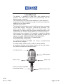
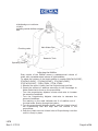
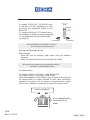
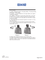
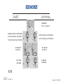
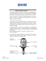
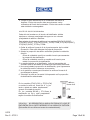
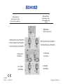
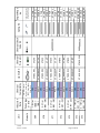
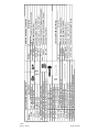
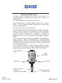
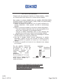
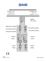
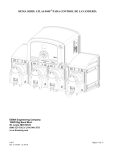
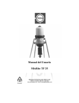
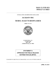
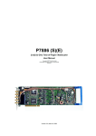
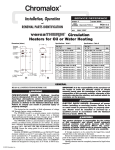
®
Proportional Injector
Bomba de dosificación proporcional
Pompe à Dosage Proportionnel
Manual del Usuario
User Manual
Manuel Utilisateur
English
p. 2 - 1 2
Espan
p. 1 3 - 2 4
Français
p. 2 5 - 3 6
www.demaeng.com E-mail: [email protected]
I-870
Rev G - 37915
Page 1 of 36
User Manual
The MixRite is powered by water flow, with minimal loss of
pressure. The water engine powers the proportioning unit. No
external power is required.
The proportioning unit injects liquid additives in direct relation to
the amount of water that passes through the motor and injects the
additives into the water system.
The water engine action:
The suction and proportioning unit is built from a piston connected
to the water engine, from which it derives its movement. The
piston moves within a cylinder with a non-return valve. The
movement of the piston within the cylinder causes the water to be
injected with the required liquid additive to be drawn through a
hose inserted into a container. It is possible to regulate the supply
ratio between the additive and the water passing through the
injector in models: 569(CW/CL/PVDF), 570(CW/CL/PVDF),
572(CW/CL/PVDF), 574(CL/CW), 571(CW/CL/PVDF),
573(CW/CL/PVDF), 575(CL/CW)
In models 571 Green and 568AG the dosing is predetermined
and can not be changed.
In models 576IN, 578IN, 577IN, 579IN the drawn additive
is transferred through a inlet bypass directly into the main water
line, without contact with the water engine.
Air release valve
Water engine
Water outlet
Suction unit with adjustable
proportional dosing
I-870
Rev G - 37915
Water inlet
Additive suction tube
Page 2 of 36
Technical Data
MixRite operates in the following conditions:
From a minimum flow rate of 20 L/H (5.3 Gal/H) and up to 2,500
L/H (660 Gal/H)
Temperature not lower than 4°C (39°F) and not higher than
40°C (104°F)
Water pressure between 0.2 Bar to 8 Bar (2.9 to 120 PSI)
The additive may be added to the water flow according to the
required dosing percentage:
0.1% to .9% in models: 569(CL/CW/PVDF)
0.3% to 2% in models: 570(CW/CL/PVDF), 571(CW/CL/PVDF),
576IN, 577IN.
0.4% to 4% in models: 572(CW/CL/PVDF), 573(CW/CL/PVDF),
578IN, 579IN.
3 % to 10% in models: 574(CL/CW), 575(CL/CW)
Fixed dosage 0.8 % in models: 571 Green, 568AG
Water pressure loss:
Pressure loss in the lower flow rates 0.1 Bar and in the higher flow
rates up to 1 Bar.
Models with 0.3%-2%: from 0.1 Bar up to 1 Bar in proportion to
the water flow
Models with 0.4%-4%: from 0.2 Bar up to 1.2 Bar in proportion to
the water flow
Models with 3%-10%: from 0.5 Bar up to 1.8 Bar in proportion to
the water flow
The MixRite inlet and outlet are ¾" BSPT male thread.
The additive tank should be placed beneath the MixRite.
Mounting the MixRite
1. Prepare the MixRite site.
The MixRite intake and outlet must
reach the intake and outlet pipes.
The MixRite must be positioned above
the liquid additives container.
2. Screw the MixRite bracket onto a wall or
any stable vertical base.
3. Press the MixRite onto the bracket.
The nipples on the MixRite must click
into the holes in the side of bracket.
I-870
Rev G - 37915
Page 3 of 36
Installation of the MixRite
Installing the MixRite on a Direct Line (in line)
1. Install onto the water line using swivel connectors and ensure
that the water flows into the MixRite in the direction indicated by
the arrows printed on the MixRite.
2. Install a 50-75 mesh (250-300 micron) filter between the valve
and the injector intake.
3. Valves have to be installed at the water line entry and exit; in
order to stop the pump's action – you should close the Valve at
the entry point.
4. Position the drawing pipe into the additive container. Ensure that
the suction pipe filter is set several millimeters above the
container’s bottom. Check to ensure that the suction pipe is not
bent or folded.
Install the MixRite on a Direct Line (In Line)
Correct Installation
I-870
Rev G - 37915
Incorrect Installation
Page 4 of 36
Installing the MixRite on a Bypass line (off line)
Where water is supplied at a higher flow rate, than the working
flow rate of the injector or where the injector isn’t needed for
continuous operation, the MixRite must be installed on a bypass line.
The bypass provides the possibility to close the operation of the
injector while water continues to flow through the line.
1. Install onto the water line using swivel connectors and ensure
that the water flows into the MixRite in the direction indicated by
the arrows printed on the MixRite.
2. Install a 50-75 mesh (250-300 micron) filter between the valve
and the injector intake.
3. Valves have to be installed at the bypass entry and exit and on
the main water line.
4. Position the liquid additive container beneath the injector. Check
to ensure that the suction pipe is not bent or folded. Position the
drawing pipe into the additive container. Ensure that the suction
pipe filter is set several millimeters above the container’s bottom.
Install the MixRite on Bypass Line (Off Line)
I-870
Rev G - 37915
Page 5 of 36
A MixRite Bypass installation
2.5 (M/h)
including mobile fertilizer solution
tank
Chocking valve
Main Water Pipe
Reservior Tank
Operating valve
Adjusting the MixRite
Every stroke of the MixRite moves a predetermined volume of
water with a predetermined volume of liquid additive.
To adjust the volume of the liquid additive in models 569(CW/CL/PVDF),
570(CW/CL/PVDF), 572(CW/CL/PVDF), 571(CW/CL/PVDF),
573(CW/CL/PVDF), 576IN, 578IN, 577IN, 579IN:
1. Remove the upper U–latch from the Proportioning Lock Nut.
2. Preset the amount of additives according to the Percentage to
Water Scale that is found on the proportioner.
• Turn the proportioning Adjuster counter clock-wise to increase
the amount of additives.
• Turn the Proportioning Adjuster clock-wise to decrease the
amount of additives.
The marking on the scale indicates the % of additive out of
the total water flowing through the injector.
3. Turn the proportioning Adjuster slightly, until the U-latch holes of
the Proportioning Lock Nut align with the notches in the
proportioner.
4. Push the U-latch into the U-latch holes of Proportioning Lock Nut
until it is firmly in place.
I-870
Rev G - 37915
Page 6 of 36
In models 574(CL/CW), 575(CL/CW) there
is noU-latch and the adjustment is done
by turning the adjustment sleeve to the
desired %.
In models 568 AG and 571 Green there is
no possibility to adjust the dosing percentage
it is predeterment by the injector model
(see page 3)
To decrease
U-latch
To increase
DO NOT REMOVE THE LOWER U-LATCH !!!
(For maintenance purpose only)
Rinsing and Cleaning the unit
After pumping
• Rinse the unit by pumping clean water from the additives
container.
• Wash the external surface of the unit with clean water.
Warning: During pumping, ensure that the additive
container is not completely empty.
Air-release Valve
In models: 568 AG, 571 Green, 570(CW/CL/PVDF),
572(CW/CL/PVDF), 574(CL/CW), 576IN, 578IN.
After initial operation of the MixRite, apply pressure to the cap (the
air release valve) for several seconds to open valve that allows
trapped air to escape. This air release is accompanied by a slight
loss of water. Release the pressure on the cap to close the valve.
Press to release air
Air is released with a
small amount of
water
I-870
Rev G - 37915
Page 7 of 36
On/Off System
In Models: 569(CW/CL/PVDF), 571(CW/CL/PVDF), 573(CW/CL/PVDF),
575(CL/CW), 577IN, 579IN.
ON position – the Knob should be in its high position, the injector
is working & pumping.
OFF position – The knob is turned and pushed down to the cap,
the water flow the injector continuous without the pumping action.
To Turn the dosage unit off and allow the free flow of water
through the MixRite:
A: The handle must be turned and pushed in so that it is in the
close state.(see 1).
To Turn the dosage unit on and allow the pumping action MixRite:
B: The handle must be turned and pulled out so that it is in the
opened state. (see 2).
Diagram 1
Diagram 2
In injectors with On/Off knob there is no air-release valve.
It is highly recommended to use the On/Off knob when the additive
container is empty or there is no need at all in the additive but the
water flow should continue.
I-870
Rev G - 37915
Page 8 of 36
Troubleshooting
Problem
MixRite does not
operate
Check
Check that the intake and outlet
valves are open
Check that the water filter isn’t
clogged
Check that water is flowing in the
line
Check that springs are not broken
Open pump lid & remove piston
Check that cylinder is not
scratched
Check that piston seals are not
damaged
MixRite does not
draw
Dismantle the suction pump and
check the suction seal for damage
The MixRite
makes scratching
noises
Check if there is liquid in the
additive container
Check if suction pipe is immersed
and not folded
Check suction filter to see if it is
blocked and if it is immersed in the
additive tank
Solution
Open the valve
Clean the filter
Open main and
outlet valve
Change the broken
spring
Change cylinder
Change the seals
Change the suction
seal
Add liquid to the
container
Straighten or
change the pipe
Clean and rinse
suction filter, Fill
liquid into tank to
cover filter
Correct installation will prevent damages and malfunctions of the MixRite
It is strongly recommended to install a back flow preventor before the injector
on the main water line.
A vacuum release unit should be installed at the outlet of the MixRite in order
to prevent undesired suction of additive when the water line is draining.
A master valve must be installed before the injector, to be opened
only for the operation of the injector to prevent water hammer
damage to the injector.
I-870
Rev G - 37915
Page 9 of 36
On/Off
models
Air release
valve models
568AG
571 Green
569(CW/CL/PVDF)
571(CW/CL/PVDF)
573(CW/CL/PVDF)
575CW
575CL
I-870
Rev G - 37915
570(CW/CL/PVDF)
572(CW/CL/PVDF)
574CW
574CL
577IN
576IN
579IN
578IN
Page 10 of 36
I-870
Rev G - 37915
Page 11 of 36
.3-2% or
500:1 - 50:1
.3-2% or
500:1 - 50:1
.4-4% or
250:1 - 25:1
.4-4% or
250:1 - 25:1
569
570
571
572
573
575
3 - 10% or
33:1 - 10:1
3 - 10% or
33:1 - 10:1
.1-.9% or
1000:1 100:1
Model #
574
CW - Aflas Chem.
Seals, CL - Viton Seals,
PVDF - Kynar Body,
Viton Seals
Percentage
or ratio
CW
CL
PVDF
CW
CL
PVDF
CW
CL
PVDF
CW
CL
PVDF
CW
CL
PVDF
CW
CL
CW
CL
Chemical
Compatiblity
Induction
Ratio
Unit
57.3VE
57.3P
57.3VE
57.3P
57.8VE
57.8P
57.8VE
57.8P
57.K02.005
57.K02.005P
57.K02.005
57.K02.005P
57.K04.012
57.K04.012P
57.K04.012
57.K04.012P
57.K10.210
57.1P
57.K01.001P
57.K10.013
57.1VE
Chemical
Piston Kit
57.K01.001
Lip Seal Kit
36000000152
36000000145
Chemical Check
Valve Kit
36000000001
36000000090
36000000001
36000000090
36000000090
36000000001
36000000090
36000000001
36000000090
36000000001
36000000090
36000000001
36000000090
36000000001
Spring Kit
57.2B
57.2B.CL
57.2B.P
57.2B
57.2B.CL
57.2B.P
57.2B
57.2B.CL
57.2B.P
57.2B
57.2B.CL
57.2B.P
57.2B
57.2B.CL
57.2B.P
57.2B.10
57.2B.10.VE
57.2B.10
57.2B.10.VE
Includes Engine Assembly
with lip seals, does not
include connecting rod
Engine Repair
Kit
I-870
Rev G - 37915
Page 12 of 36
Number
57.4B
57.1
57.10.16
57.10.17
57.10.17.10
57.10.31
57.10.31.B
57.10.5
57.10.32
57.10.7.2
57.10.7.4
57.10.7.10
57.10.8
57.10.3
57.10.3.B
57.K2B.222
57.K4B.244
57.K10.002
Description
Top Cover with Air Release
Top Cover with On/Off
Upper U-Latch
Lower U-Latch
10% Model Lower Nut Latch
MixRite Grey Nylon Body 569-575
MixRite Grey Nylon Body Bypass Unit
Cylinder Support Black
Cylinder Support Nut, Blk
Chemical Cylinder 570/571
Chemical Cylinder 572/573
Chemical Cylinder 574/575
Chemical Adjustment Sleeve 569-573
Connecting Rod 570-573
Connecting Rod 576-579
2% Bypass Piston Kit for 576-577
4% Bypass Piston Kit for 578-579
Conical Bypass Seal Kit for Connecting Rod
Common MixRite Repair Parts
Description
Common MixRite O-Rings
Description
3/4" NPT Female to Female Check Valve
MixRite Mounting Bracket
Chemical Suction Filter 574/575
Tubing Strainer with Marble Weight
Chemical Pickup Kit for Aggressive Chemicals
MixRite 3/4" Female to Female Strainer
Chemical Foot Valve
Aflas O-ring Cylinder Support 220
57.10.44A
Aflas O-ring Chemical Cylinder
57.10.46A
57.K02.005CW Aflas O-ring Kit for 2% Unit
57.K04.0123CW Aflast O-ring Kit for 4% Unit
Viton Chemical Cylinder O-Ring
57.10.46.2V
Number
Number
57.20.8
57.10.65
57.10.36.10
57.113.1
57.KCPA
50.41.1
100.16V
Common MixRite Accessories
®
Bomba de dosificación
proporcional
Manual del Usuario
I-870
Rev G - 37915
Page 13 of 36
Manual del Usuario
La bomba dosificadora proporcional MixRite se acciona gracias al
flujo de agua entrante. Por tanto no es necesario el abastecimiento
de energía eléctrica para ponerla en funcionamiento. Su especial
diseño hace que la pérdida de presión en este proceso sea mínima.
Al ser proporcional, el volumen de aditivos líquidos que la bomba
MixRite inyecta y mezcla depende directamente del volumen de
agua que entra en la bomba.
Cómo trabaja el motor hidráulico:
La unidad de inyección proporcional utiliza un pistón que se acciona
mediante el motor hidráulico. Dicho pistón se mueve dentro de una
válvula anti-retorno cilíndrica. Este movimiento produce la succión
necesaria para que el aditivo pase al interior de la bomba en la
proporción deseada.
Es posible regular la proporción de aditivo en los siguientes
modelos de bomba MixRite : 569(CW/CL/PVDF), 570(CW/CL/PVDF),
572(CW/CL/PVDF) 574(CL/CW), 571(CW/CL/PVDF), 573(CW/CL/PVDF),
575(CL/CW).
.
En los siguientes modelos, la proporción de inyección es fija:
571 Green, 568AG
En los siguientes modelos, el aditivo se inyecta fuera del cuerpo de
la bomba, y por tanto no llega a estar en contacto con el motor
hidráulico: 576IN, 577IN, 578IN, 579IN.
Válvula de
vaciado de aire
Motor hidráulico
Salida de agua
Unidad de succión con
dosificación
proporcional ajustable
I-870
Rev G - 37915
Entrada de
agua
Tubo de succión del
aditivio a dosificar
Page 14 of 36
INFORMACIÓN TÉCNICA
Los dosificadores MixRite
operan en las siguientes condiciones:
• CAUDAL: entre 20 L/H (5.3 Gal/H) y 2.500 L/H (660 Gal/H)
• TEMPERATURA: entre 4° C (39° F) y 40° C (104° F)
• PRESIÓN DEL AGUA ENTRANTE: 0.2 Bar (2.9 PSI) y 8 Bar (120
PSI)
Los dosificadores MixRite
dosificación:
•
•
•
•
•
permiten las siguientes proporciones de
0.1% al 0.9%, Modelos: 569(CW/CL/PVDF)
0.3% al 2%, Modelos: 570(CW/CL/PVDF), 571(CW/CL/PVDF), 576IN, 577IN
0.4% al 4%, Modelos: 572(CW/CL/PVDF), 573(CW/CL/PVDF), 578IN, 579IN
3% al 10%, Modelos: 574(CL/CW), 575(CL/CW)
Dosificación fija al 0.8%, Modelos: 571 Green, 568 AG
Pérdidas de presión en los dosificadores MixRite :
- Pérdida de presión a bajos caudales de 0,1 Bar, y de hasta 1 Bar
a altos caudales
- En modelos de dosificación variable entre 0,3% y 2% la pérdida
de presión varía entre 0,1 Bar y 1 Bar en proporción al caudal
que pase por la bomba
- En modelos de dosificación variable entre 0,4% y 4% la pérdida
de presión varía entre 0,2 Bar y 1,2 Bar en proporción al caudal
que pase por la bomba
- En modelos de dosificación variable entre 3% y 10% la pérdida
de presión varía entre 0,5 Bar y 1,8 Bar en proporción al caudal
que pase por la bomba
Otros datos:
• Las tomas de entrada y salida de la bomba incorporan machos
roscados (3/4” BSPT).
• El tanque de aditivo a dosificar debe estar situado debajo de la
bomba.
I-870
Rev G - 37915
Page 15 of 36
MONTAJE DEL DOSIFICADOR MixRite
1. Preparación del emplazamiento del
dosificador MixRite
- Las tomas de entrada y salida a la
bomba deben estar al alcance de las
tuberías de entrada y salida
- El dosificador MixRite debe estar
situado encima del contenedor de
aditivo a dosificar.
2. Atornillar el accesorio de fijación en
un muro o cualquier otra base
vertical estable.
3. Encajar el dosificador en el
accesorio de fijación. Para ello, los
salientes del dosificador deben
ajustarse en los agujeros del
accesorio fijador.
INSTALACIÓN DEL DOSIFICADOR MixRite
Instalación del dosificador en línea
Válvula
Válvula
anti
retorno
Válvula
limitadora
de presión
Manómetro
Válvula Válvula
anti sifón
Filtero
1. Conectar el dosificador a la línea de entrada de agua utilizando
las uniones roscadas adecuadas. Verificar que el agua fluye en
la dirección que se indica en la flecha impresa en el cuerpo del
dosificador.
2. Instalar un filtro de malla del tipo 50-75 (250-300 micras) entre
la válvula de entrada a la unidad de succión y el punto de
entrada del aditivo a dosificar.
I-870
Rev G - 37915
Page 16 of 36
3. Instalar válvulas en los puntos de entrada y salida del
dosificador. Nótese que para detener el funcionamiento del
dosificador se debe cerrar la válvula del lado de la entrada de
agua al dosificador.
4. Colocar el tubo de succión en el contenedor del aditivo a
dosificar. El tubo de succión debe encontrarse a varios
milímetros del fondo del contenedor, dicho tubo de succión no
debe estar doblado o estrangulado.
Instalación del dosificador en by-pass
Válvula A
Válvula
Válvula
Válvula
anti
retorno
Válvula Filtero
limitadora
de presión
Válvula
anti sifón
Válvula
Válvula
La instalación en modo by-pass es necesaria en las siguientes
situaciones:
a) Cuando el caudal de la entrada de agua es mayor que el caudal
máximo de trabajo de la bomba.
b) Cuando no se necesita que el dosificador trabaje de manera
continúa, sino que se puede interrumpir su uso mientras el agua
sigue fluyendo fuera del dosificador.
1. Conectar el dosificador a la línea de entrada de agua utilizando
las adecuadas uniones roscadas. Verificar que el agua fluye en la
dirección que se indica en la flecha impresa en el cuerpo del
dosificador.
2. Instalar un filtro de malla del tipo 50-75 (250-300 micras) entre
la válvula de entrada y el punto de entrada del aditivo a
dosificar.
3. Instalar válvulas en la entrada y salida del dosificador y en la
línea principal de flujo de agua.
I-870
Rev G - 37915
Page 17 of 36
4. Colocar el tubo de succión en el contenedor del aditivo a
dosificar. El tubo de succión debe encontrarse a varios
milímetros del fondo del contenedor. El tubo de succión no debe
estar doblado o estrangulado.
AJUSTE DEL DOSIFICADOR MixRite
Cada ciclo de bombeo en el interior del dosificador MixRite
expulsa un volumen preajustado de agua con un volumen
preajustado de aditivo a dosificar.
Para ajustar el volumen de aditivo en los modelos 569(CW/CL/PVDF),
570(CW/CL/PVDF), 572(CW/CL/PVDF), 576IN, 578IN, 571(CW/CL/PVDF),
573(CW/CL/PVDF), 577IN y 578IN:
1. Quitar la anilla en forma de U de la parte superior de la unidad
de succión. Esta anilla bloquea el ajuste de proporción.
2. Ajustar la proporción de aditivo a dosificar girando la unidad de
succión.
Gírese la unidad de succión en sentido horario para aumentar
la proporción de dosificación.
Gírese la unidad de succión en sentido anti-horario para
reducir la proporción de dosificación
3. La escala impresa en el dosificador indica el porcentaje del
volumen total de entrada a la bomba que esta siendo dosificado.
4. Una vez ajustada la proporción de dosificación, girar ligeramente
la unidad de succión hasta que se encuentre
5. en la posición correcta para introducir la anilla en forma de U
que bloquea la misma.
6. Introducir la anilla en forma de U bloqueando así la proporción
de dosificación seleccionada.
n
Ailla en
forma de U
En los modelos 574(CL/CW) y 575(CL/CW)
no existe la anilla en forma de U l y por
tanto e ajuste se realiza simplemente
girando la unidad de succión.
En los modelos 568 AG y 571 Green, la
dosificación es fija y está preajustada
según el modelo de dosificadora.
To decrease
To increase
ATENCIÓN: NO DESMONTAR LA ANILLA EN FORMA DE U QUE SE
ENCUENTRA EN LA PARTE INFERIOR DE LA UNIDAD DE SUCCIÓN.
(Esta anilla sólo se utiliza en tareas de mantenimiento).
I-870
Rev G - 37915
Page 18 of 36
ENJUAGADO Y LIMPIEZA DEL DOSIFICADOR MixRite
Inmediatamente después de su utilización:
- Enjuagar el dosificador inyectando agua limpia a través de la
unidad de succión.
- Limpiar la superficie exterior del dosificador con agua limpia.
ATENCIÓN:
Asegurarse durante la utilización del dosificador, que el contenedor
de aditivo no se vacía.
VÁLVULA DE VACIADO DE AIRE
Los modelos 568 AG, 571 Green, 570(CW/CL/PVDF), 572(CW/CL/PVDF),
574(CL/CW), 576IN, 579IN incorporan una válvula de vaciado de aire.
Inmediatamente después de la puesta en funcionamiento,
presiónese hacia abajo el botón de vaciado de aire durante unos
segundos. El aire atrapado dentro del dosificador saldrá
acompañado de una pequeña cantidad de agua.
Nótese que los dosificadores con válvula de vaciado de aire no
pueden disponer de sistema de puesta en marcha/paro.
Presionar para liberar el aire
el aire sale de la bomba
junto con una pequeña
cantidad de agua.
SISTEMA DE PUESTA EN MARCHA/PARO
Los modelos 569(CW/CL/PVDF),571(CW/CL/PVDF), 573(CW/CL/PVDF),
575(CL/CW), 577IN y 579IN incorporan un sistema de puesta en
marcha/paro.
Nótese que los dosificadores con sistema de puesta en
marcha/paro no pueden disponer de válvula de vaciado de aire.
Posición Marcha:
El mando de accionamiento se encuentra en su
posición más alta, la bomba está trabajando y bombeando.
I-870
Rev G - 37915
Page 19 of 36
Posición Paro:
El mando de accionamiento se encuentra en su
posición más baja, el flujo por el interior de la bomba, pero esta no
está trabajando ni bombeando.
Para detener la bomba dosificadora y por tanto permitir el flujo
libre por el interior de la misma:
- Girar el mando de accionamiento en sentido anti-horario de
modo que este quede en la “posición paro”, (figura 1).
Para poner en funcionamiento la bomba dosificadora y por tanto
permitir el bombeo:
- Girar el mando de accionamiento en sentido horario de modo
que este quede en la “posición marcha”, (figura 2).
Figura 1
Figura 2
ATENCIÓN:
Es especialmente recomendable llevar el mando de accionamiento a la
posición de paro cuando el depósito de aditivo a dosificar está vacío o
cuando no es necesario dosificar al aditivo auque el flujo a través de la
bomba deba mantenerse.
I-870
Rev G - 37915
Page 20 of 36
RESOLUCIÓN DE PROBLEMAS
P r oble m a
La bomba
MixRite
no
funciona
La bomba
MixRite
no
succiona el
aditivo
La bomba
MixRite
hace ruidos
anormales
de fricción.
R e v is ión
Revisar si las válvulas de entrada y
salida están abiertas
Revisar si el filtro de aditivo se
encuentra obstruido
Revisar si el agua está fluyendo en la
línea de entrada a la bomba
Revisar si los muelles de la bomba
están dañados. Para ello, abrir la tapa
de la bomba y extraer el pistón.
Revisar si el cilindro está deteriorado.
Revisar si las juntas de estanqueidad
del cilindro están deterioradas.
Desmontar la unidad de succión y
revisar si la junta de estanqueidad está
dañada.
Revisar si hay líquido en el depósito de
aditivo
Revisar si el tubo de succión esta
sumergido y si no está doblado o
estrangulado de algún modo.
Revisar si el tubo de succión está
bloqueado
S olu ción
Abrir las válvulas.
Limpiar el filtro de aditivo.
Abrir la válvula de entrada
de la línea de entrada de
agua a la bomba y la válvula
de salida de agua de la
bomba.
Cambiar el pistón dañado.
Cambiar el cilindro.
Cambiar el pistón.
Cambiar la junta de
estanqueidad de la unidad
de succión.
Añadir líquido al depósito de
aditivo.
Sumergir adecuadamente el
tubo de succión y eliminar
estrangulamientos en el
tubo de succión o sustituirlo.
Limpiar el filtro del tubo de
succión
LA INSTALACIÓN CORRECTA ES LA MEJOR MANERA DE PREVENIR
DAÑOS Y AVERÍAS DE LA BOMBA MixRite
Se recomienda especialmente instalar una válvula anti-retorno antes de la
entrada de agua a la bomba en la línea principal de flujo. Se recomienda
especialmente instalar una unidad de vaciado en la salida de la bomba MixRite
para prevenir la succión de aditivo cuando la línea principal de agua se está
drenando.
Es importante instalar una válvula de apertura/cierre antes de la bomba
en la línea principal. Esta válvula se debe abrir sólo cuando se necesite
utilizar la bomba. La instalación de este modo previene averías en la
bomba por causa del efecto “golpe de ariete”.
I-870
Rev G - 37915
Page 21 of 36
Modelos
système de
marchn/paro
Modelos
valvula de
vaciado de
aire
568AG
571 Green
569(CW/CL/PVDF)
571(CW/CL/PVDF)
573(CW/CL/PVDF)
575CW
575CL
I-870
Rev G - 37915
570(CW/CL/PVDF)
572(CW/CL/PVDF)
574CW
574CL
577IN
576IN
579IN
578IN
Page 22 of 36
I-870
Rev G - 37915
Page 23 of 36
.3-2% or
500:1 - 50:1
.3-2% or
500:1 - 50:1
.4-4% or
250:1 - 25:1
.4-4% or
250:1 - 25:1
569
570
571
572
573
575
3 - 10% or
33:1 - 10:1
3 - 10% or
33:1 - 10:1
.1-.9% or
1000:1 100:1
Model #
574
CW - Aflas Chem.
Seals, CL - Viton Seals,
PVDF - Kynar Body,
Viton Seals
Percentage
or ratio
CW
CL
PVDF
CW
CL
PVDF
CW
CL
PVDF
CW
CL
PVDF
CW
CL
PVDF
CW
CL
CW
CL
Chemical
Compatiblity
Induction
Ratio
Unit
57.3VE
57.3P
57.3VE
57.3P
57.8VE
57.8P
57.8VE
57.8P
57.K02.005
57.K02.005P
57.K02.005
57.K02.005P
57.K04.012
57.K04.012P
57.K04.012
57.K04.012P
57.K10.210
57.1P
57.K01.001P
57.K10.013
57.1VE
Chemical
Piston Kit
57.K01.001
Lip Seal Kit
36000000152
36000000145
Chemical Check
Valve Kit
36000000001
36000000090
36000000001
36000000090
36000000090
36000000001
36000000090
36000000001
36000000090
36000000001
36000000090
36000000001
36000000090
36000000001
Spring Kit
57.2B
57.2B.CL
57.2B.P
57.2B
57.2B.CL
57.2B.P
57.2B
57.2B.CL
57.2B.P
57.2B
57.2B.CL
57.2B.P
57.2B
57.2B.CL
57.2B.P
57.2B.10
57.2B.10.VE
57.2B.10
57.2B.10.VE
Includes Engine Assembly
with lip seals, does not
include connecting rod
Engine Repair
Kit
I-870
Rev G - 37915
Page 24 of 36
Number
57.4B
57.1
57.10.16
57.10.17
57.10.17.10
57.10.31
57.10.31.B
57.10.5
57.10.32
57.10.7.2
57.10.7.4
57.10.7.10
57.10.8
57.10.3
57.10.3.B
57.K2B.222
57.K4B.244
57.K10.002
Description
Top Cover with Air Release
Top Cover with On/Off
Upper U-Latch
Lower U-Latch
10% Model Lower Nut Latch
MixRite Grey Nylon Body 569-575
MixRite Grey Nylon Body Bypass Unit
Cylinder Support Black
Cylinder Support Nut, Blk
Chemical Cylinder 570/571
Chemical Cylinder 572/573
Chemical Cylinder 574/575
Chemical Adjustment Sleeve 569-573
Connecting Rod 570-573
Connecting Rod 576-579
2% Bypass Piston Kit for 576-577
4% Bypass Piston Kit for 578-579
Conical Bypass Seal Kit for Connecting Rod
Common MixRite Repair Parts
Description
Common MixRite O-Rings
Description
3/4" NPT Female to Female Check Valve
MixRite Mounting Bracket
Chemical Suction Filter 574/575
Tubing Strainer with Marble Weight
Chemical Pickup Kit for Aggressive Chemicals
MixRite 3/4" Female to Female Strainer
Chemical Foot Valve
Aflas O-ring Cylinder Support 220
57.10.44A
Aflas O-ring Chemical Cylinder
57.10.46A
57.K02.005CW Aflas O-ring Kit for 2% Unit
57.K04.0123CW Aflast O-ring Kit for 4% Unit
Viton Chemical Cylinder O-Ring
57.10.46.2V
Number
Number
57.20.8
57.10.65
57.10.36.10
57.113.1
57.KCPA
50.41.1
100.16V
Common MixRite Accessories
®
Pompe à Dosage
Proportionnel
Manuel Utilisateur
I-870
Rev G - 37915
Page 25 of 36
Manuel Utilisateur
Le Doseur MixRite fonctionne via le flux d’eau entrant. Il ne
nécessite donc pas d’alimentation électrique pour le mettre en
fonctionnement.
Son design permet de réduire la perte de pression.
Etant proportionnel, le volume d’additif liquide que le doseur
MixRite injecte et mélange dépend directement du volume d’eau
qui entre dans le doseur.
Comment fonctionne le moteur hydraulique:
Le module d’injection proportionnelle utilise un piston s’actionnant
grâce au moteur hydraulique. Immédiatement le piston se déplace
à l’intérieur d’une soupape anti-retour cylindrique. Ce mouvement
produit l’aspiration nécessaire à l’introduction de l’additif à
l’intérieur du doseur tout en respectant le pourcentage du mélange
désiré.
Il est possible de régler la proportion d’additif sur les modèles de
Doseurs MixRite suivants: 569(CW/CL/PVDF), 570(CW/CL/PVDF),
572(CW/CL/PVDF) 574(CL/CW), 571(CW/CL/PVDF), 572(CW/CL/PVDF),
575(CL/CW) Pour les modèles suivants, la proportion de mélange est
fixe: 571 Green, 568 AG.
Pour les modèles qui suivent, l’additif s’injecte en-dehors du corps
de la pompe. Cela permet au moteur hydraulique de ne jamais
entrer en contact avec un additif : 576IN, 578IN, 577IN,579IN.
Robinet purgeur
d´air
Moteur
hydraulique
Sortie d´eau
Unité d´aspiration
à dosage
proportionnnel ajustable
I-870
Rev G - 37915
Entrée eau
Tube d´aspiration de
produit à doser
Page 26 of 36
INFORMATIONS TECHNIQUES
Les Doseurs MixRite
fonctionnent avec les conditions suivantes:
• DEBIT: entre 20 l/h (5.3 Gal/H) et 2.500 l/h (660Gal/H)
• TEMPERATURE: entre 4° C (39° F) et 40° C (104° F)
• PRESSION D’EAU EN ENTRÉE: entre 0.2 Bar (2.9 psi) et 8 Bar (120 psi)
Les Doseurs MixRite
suivants:
•
•
•
•
•
permettent les pourcentages de mélange
0.1% à 0.9%, Modèles: 569(CW/CL/PVDF)
0.3% à 2%, Modèles: 570(CW/CL/PVDF), 571(CW/CL/PVDF), 576IN, 577IN
0.4% à 4%, Modèles: 572(CW/CL/PVDF), 573(CW/CL/PVDF), 578IN, 579IN
3% à 10%, Modèles: 574(CL/CW), 575(CL/CW)
Dosage fixe à 0.8%, Modèles: 571 Green, 568 AG
Pertes de pression sur les Doseurs MixRite :
- Pertes de pression à bas débits de l’ordre de 0,1 Bar, et jusqu’à
1 Bar à hauts débits.
- Sur les modèles à pourcentage variable entre 0,3% et 2%, la
perte de pression varie entre 0,1 Bar et 1 Bar
proportionnellement au débit qui passe par la pompe.
- Sur les modèles à pourcentage variable entre 0,4% et 4%, la
perte de pression varie entre 0,2 Bar et 1,2 Bar
proportionnellement au débit qui passe par la pompe.
- Sur les modèles à pourcentage variable entre 3% et 10%, la
perte de pression varie entre 0,5 Bar et 1,8 Bar
proportionnellement au débit qui passe par la pompe.
Autres données:
• Les connexions d’entrée et de sortie de la pompe sont des
embouts mâles (3/4” BSPT).
• Le réservoir de l’additif doit être situé au dessous de la pompe.
MONTAGE DU DOSEUR MixRite
1. Préparation de l’emplacement du doseur MixRite
- Les connexions d’entrée et de sortie de la pompe
doivent être au niveau des tuyaux d’entrée et de
sortie à brancher.
- Le Doseur MixRite doit être situé au dessus du
réservoir de l’additif.
2. Visser le socle de fixation contre un mur ou sur
tout autre support vertical stable.
3. Insérer le doseur dans le socle de fixation. Pour
cela, les tiges cylindriques du doseur doivent se
clipser dans les trous du socle de fixation.
I-870
Rev G - 37915
Page 27 of 36
INSTALLATION DU DOSEUR MixRite
INSTALLATION DU DOSEUR EN LIGNE
Vanne
Manomètre
Clapet
Regulateur
Annti-retour De pression
Vanne
Vanne
Anti- siphon
Filtre
1. Brancher le doseur à l’entrée d’eau en utilisant les embouts
adéquats. Vérifier que l’eau circule dans la direction indiquée par
la flèche présente sur le corps du doseur.
2. Installer un filtre à tamis d’une finesse de filtration de 250 à 300
microns entre le robinet d’entrée du module d’aspiration et le
point d’entrée de l’additif.
3. Installer les robinets dans les points d’entrée et sortie du doseur.
Notez que pour arrêter le fonctionnement du doseur, il faut
fermer le robinet côté entrée d’eau du doseur.
4. Placer le tube d’aspiration dans le réservoir de l’additif. Le tube
d’aspiration doit se trouver à quelques millimètres du fond du
réservoir. De plus, le tube d’aspiration ne doit ni être plié ni
étranglé.
Installation correcte
I-870
Rev G - 37915
Installation incorrecte
Page 28 of 36
INSTALLATION DU DOSEUR EN by-pass
Vanne A
Vanne
Clapet
Antiretour
Vanne
Regulateur
de
Filtre
pression
Vanne Antisiphon
Vanne
Vanne
L’installation en mode by-pass est nécessaire dans les situations
suivantes:
a) Quand le débit d’entrée de l’eau est supérieur au débit maximum
de travail de la pompe.
b) Quand il n’est pas nécessaire que le doseur travaille de manière
continue, vous pouvez interrompre son utilisation pendant
que l’eau circule hors du doseur.
1. Brancher le doseur à l’entrée d’eau en utilisant les embouts
adéquats. Vérifier que l’eau circule dans la direction indiquée par
la flèche présente sur le corps du doseur.
2. Installer un filtre à tamis de finesse 250 à 300 microns entre le
robinet d’entrée du module d’aspiration et le point d’entrée de
l’additif.
3. Installer les robinets à l’entrée et à la sortie du doseur et dans la
ligne principale du circuit d’eau.
4. Placer le tube d’aspiration dans le réservoir de l’additif. Le tube
d’aspiration doit se trouver à quelques millimètres du fond du
réservoir. De plus, le tube d’aspiration ne doit ni être plié ni
étranglé.
Un doseur MixRite
installe en Bypass 2.5
(M/h)
incluant un bac de
fertilsation mobile
Vanne de
reglage
Vanne
I-870
Rev G - 37915
Conduite
principale
Bac de
fertilisation
Page 29 of 36
AJUSTAGE DU DOSEUR MixRite
Chaque cycle de pompage à l’intérieur du Doseur MixRite rejette
un volume précis d’eau combiné à un volume précis d’additif.
Pour ajuster le volume d’additif dans les modèles 569(CW/CL/PVDF),
570(CW/CL/PVDF) 572(CW/CL/PVDF), 576IN, 578IN, 571(CW/CL/PVDF),
573(CW/CL/PVDF), 577IN y 579IN:
1. Enlever la goupille en forme de U de la partie supérieure du
module d’aspiration. Cette goupille verrouille le pourcentage
d’additif.
2. Ajuster la proportion d’additif en tournant le module d’aspiration.
- Tournez le module d’aspiration dans le sens des aiguilles d’une
montre pour augmenter le pourcentage d’additif.
- Tournez le module d’aspiration dans le sens contraire des
aiguilles d’une montre pour réduire le pourcentage d’additif.
3. L’échelle utilisée sur le doseur indique le pourcentage du volume
total à l’entrée de la pompe qui a été dosé.
4. Une fois le dosage ajusté, tournez légèrement le module
d’aspiration jusqu’à ce que vous trouviez la position correcte
pour réintroduire la goupille en forme du U qui bloquera le
réglage.
5. Introduire la goupille en forme du U en bloquant votre réglage
sur le doseur.
Sur les modèles 574(CL/CW)
et 575(CL/CW), il n’existe pas
de goupille en U et par
conséquent l’ajustage se
réalise
simplement
par
rotation
du
module
d’aspiration.
Sur les modèles 5 7 1 G r e e n
et 5 6 8 A G le réglage est fixe
et pré ajusté suivant le
modèle de doseur.
Goupille en
forme de U
Pour réduire
Pour augmenter
ATTENTION : NE PAS DÉMONTER LA GOUPILLE EN FORME
DE U QUI SE TROUVE SUR LA PARTIE INFÉRIEURE DU
MODULE D’ASPIRATION. (Cette goupille s’utilise seulement
pour la maintenance du système).
I-870
Rev G - 37915
Page 30 of 36
RINCAGE et NETTOYAGE DU DOSEUR MixRite
Immédiatement après utilisation:
Rincer le doseur en injectant de l’eau claire à travers le
module d’aspiration.
Nettoyer la surface extérieure du doseur avec de l’eau
claire.
ATTENTION : S’ASSURER DURANT L’UTILISATION DU DOSEUR, QUE LE RÉSERVOIR
DE L’ADDITIF N’EST PAS VIDE
ROBINET DE PURGE D’AIR
Les modèles 568 AG, 571 Green, 569(CW/CL/PVDF), 570(CW/CL/PVDF),
572(CW/CL/PVDF), 574(CL/CW), 576IN, 578IN intègrent un robinet
de purge d’air. Immédiatement après la mise en fonctionnement,
pressez vers le bas le bouton purgeur d’air pendant quelques
secondes. L’air stocké dans le doseur sortira avec une petite quantité
d’eau. Notez que les doseurs à robinet purgeur d’air ne peuvent
pas disposer de système de position marche/arrêt.
Presser pour libérer l'air
De L'air sort de la
pompe avec petite
quantité d'eau
SYSTÈME de POSITION MARCHE/ARRÊT
Les modèles 569(CW/CL/PVDF) 571(CW/CL/PVDF), 573(CW/CL/PVDF),
575(CL/CW), 577IN et 579IN intègrent un système de position marche/arrêt.
Notez que les doseurs avec système de position marche/arrêt ne
peuvent pas disposer de robinet de purge d’air.
I-870
Rev G - 37915
Page 31 of 36
Position Marche:
La commande de mise en route se trouve dans
la position la plus haute, la pompe travaille et pompe.
Position Arrêt:
La commande de mise en route se trouve dans la
position la plus basse, l’eau circule dans la pompe, mais celle-ci ne
travaille pas et ne pompe pas.
Pour arrêter le doseur et ainsi permettre la circulation libre à
l’intérieur :
-Tourner la commande d’actionnement dans le sens contraire
des aiguilles d’une montre, de sorte que celui-ci reste en position
« arrêt » (figure 1).
Pour mettre le doseur en fonctionnement et permettre le
pompage :
-Tourner la commande d’actionnement dans le sens des aiguilles
d’une montre, de sorte que celui-ci reste en position « marche »,
(figure 2).
Figure 1
Figure 2
ATTENTION : IL EST PARTICULIÈREMENT RECOMMANDÉ
DE METTRE LA COMMANDE D’ACTIONNEMENT EN
POSITION D’ARRÊT QUAND LE RÉSERVOIR D’ADDITIF EST
VIDE OU QUAND IL N’EST PAS NÉCESSAIRE DE DOSER
L’ADDITIF LORSQUE LA CIRCULATION A TRAVERS LA
POMPE EST MAINTENUE.
I-870
Rev G - 37915
Page 32 of 36
RÉSOLUTION DE PROBLÈMES
Problème
Contrôle
Solution
Vérifier si les robinets
d’entrée et de sortie
sont ouverts.
Ouvrir les robinets.
Vérifier si le filtre de
l’additif n’est pas
bouché.
Nettoyer le filtre de
l’additif.
Vérifier si l’eau circule
bien dans le circuit
d’entrée de la pompe.
Ouvrir le robinet du
circuit d’entrée d’eau à
la pompe et celui de
sortie de la pompe.
Vérifier si les ressorts
de la pompe sont
endommagés. Pour
cela, ouvrir le
couvercle de la pompe
et sortir le piston.
Changer le piston
défectueux.
Vérifier si le cylindre
est détérioré.
Changer le cylindre.
Vérifier si les joints
d’étanchéité du
cylindre sont
détériorés.
Changer le piston.
La pompe
MixRite
n’aspire pas
l’additif
Démonter le module
d’aspiration et vérifier
si le joint d’étanchéité
est endommagé.
Changer le joint
d’étanchéité du
module d’aspiration.
La pompe
MixRite
fait
des bruits
anormaux de
frottement.
Vérifier s’il y a du
liquide dans le
réservoir de l’additif.
Ajouter du liquide
dans le réservoir de
l’additif.
Vérifier si le tuyau
d’aspiration est
submergé et s’il n’est
pas plié ou étranglé.
Submerger de
manière adaptée le
tuyau d’aspiration et
éliminer
l’étranglement du
tuyau ou le remplacer.
Vérifier si le tuyau
d’aspiration n’est pas
bouché.
Nettoyer le filtre du
tuyau d’aspiration.
La pompe
MixRite
ne
fonctionne pas
L’INSTALLATION CORRECTE EST LE MEILLEUR MOYEN
D’ÉVITER LA PANNE OU D’ENDOMMAGER LA POMPE
MixRite.
Il est recommandé d’installer un clapet anti-retour avant l’entrée
d’eau de la pompe dans le circuit principal. Il est également
recommandé d’installer un module de vidange à la sortie de la
pompe MixRite pour éviter l’aspiration de l’additif quand le circuit
d’eau principal est en train de se vider.
I-870
Rev G - 37915
Il est important d’installer un robinet d’ouverture/fermeture avant
la pompe sur le circuit principal. Ce robinet doit être ouvert
seulement quand il est nécessaire d’utiliser la pompe. L’installation
faite de cette façon évite les pannes dans la pompe pouvant
causer l’effet “coup de bélier”.
Page 33 of 36
Modèles avec
système de
marche/arrêt
Modèles avec
robinet
purgeur d’air
568AG
571 Green
569(CW/CL/PVDF)
571(CW/CL/PVDF)
573(CW/CL/PVDF)
575CW
575CL
I-870
Rev G - 37915
570(CW/CL/PVDF)
572(CW/CL/PVDF)
574CW
574CL
577IN
576IN
579IN
578IN
Page 34 of 36
I-870
Rev G - 37915
Page 35 of 36
.3-2% or
500:1 - 50:1
.3-2% or
500:1 - 50:1
.4-4% or
250:1 - 25:1
.4-4% or
250:1 - 25:1
569
570
571
572
573
575
3 - 10% or
33:1 - 10:1
3 - 10% or
33:1 - 10:1
.1-.9% or
1000:1 100:1
Model #
574
CW - Aflas Chem.
Seals, CL - Viton Seals,
PVDF - Kynar Body,
Viton Seals
Percentage
or ratio
CW
CL
PVDF
CW
CL
PVDF
CW
CL
PVDF
CW
CL
PVDF
CW
CL
PVDF
CW
CL
CW
CL
Chemical
Compatiblity
Induction
Ratio
Unit
57.3VE
57.3P
57.3VE
57.3P
57.8VE
57.8P
57.8VE
57.K02.005
57.K02.005P
57.K02.005
57.K02.005P
57.K04.012
57.K04.012P
57.K04.012
57.K10.013
57.K10.210
57.8P
57.1P
57.K01.001P
57.K04.012P
57.1VE
Chemical
Piston Kit
57.K01.001
Lip Seal Kit
36000000152
36000000145
Chemical Check
Valve Kit
36000000001
36000000090
36000000001
36000000090
36000000090
36000000001
36000000090
36000000001
36000000090
36000000001
36000000090
36000000001
36000000090
36000000001
Spring Kit
57.2B
57.2B.CL
57.2B.P
57.2B
57.2B.CL
57.2B.P
57.2B
57.2B.CL
57.2B.P
57.2B
57.2B.CL
57.2B.P
57.2B
57.2B.CL
57.2B.P
57.2B.10
57.2B.10.VE
57.2B.10
57.2B.10.VE
Includes Engine Assembly
with lip seals, does not
include connecting rod
Engine Repair
Kit
I-870
Rev G - 37915
Page 36 of 36
Number
57.4B
57.1
57.10.16
57.10.17
57.10.17.10
57.10.31
57.10.31.B
57.10.5
57.10.32
57.10.7.2
57.10.7.4
57.10.7.10
57.10.8
57.10.3
57.10.3.B
57.K2B.222
57.K4B.244
57.K10.002
Description
Top Cover with Air Release
Top Cover with On/Off
Upper U-Latch
Lower U-Latch
10% Model Lower Nut Latch
MixRite Grey Nylon Body 569-575
MixRite Grey Nylon Body Bypass Unit
Cylinder Support Black
Cylinder Support Nut, Blk
Chemical Cylinder 570/571
Chemical Cylinder 572/573
Chemical Cylinder 574/575
Chemical Adjustment Sleeve 569-573
Connecting Rod 570-573
Connecting Rod 576-579
2% Bypass Piston Kit for 576-577
4% Bypass Piston Kit for 578-579
Conical Bypass Seal Kit for Connecting Rod
Common MixRite Repair Parts
Description
Common MixRite O-Rings
Description
3/4" NPT Female to Female Check Valve
MixRite Mounting Bracket
Chemical Suction Filter 574/575
Tubing Strainer with Marble Weight
Chemical Pickup Kit for Aggressive Chemicals
MixRite 3/4" Female to Female Strainer
Chemical Foot Valve
Aflas O-ring Cylinder Support 220
57.10.44A
Aflas O-ring Chemical Cylinder
57.10.46A
57.K02.005CW Aflas O-ring Kit for 2% Unit
57.K04.0123CW Aflast O-ring Kit for 4% Unit
Viton Chemical Cylinder O-Ring
57.10.46.2V
Number
Number
57.20.8
57.10.65
57.10.36.10
57.113.1
57.KCPA
50.41.1
100.16V
Common MixRite Accessories