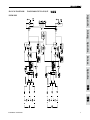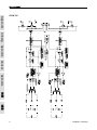
1
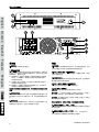
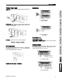
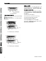
ICON700 English Deutsch Español ICON 300 ICON 700 Français Português 日本語 User's Manual Benutzerhandbuch Manual del Usuario Mode d'emploi Manual do Usuário 取扱説明書 使用手册 简体中文 English ICON 300 ICON 700 Deutsch CONTRACTOR POWER AMPLIFIER AMPLIFICADOR DE POTENCIA PARA CONTRATISTA 功率放大器 Español ENGLISH ......... ........................................I ESPAÑOL . . . . . . . . . . . . . . . . . . . . . . . . . . . . . . . . . . . . . . . . . . . . . . . . II 简体中文 . . . . . . . . . . . . . . . . . . . . . . . . . . . . . . . . . . . . . . . . . . . . . . . III Français Português 日本語 简体中文 V1.1 02/08/2012 English USER'S MANUAL CONTENTS 1 PRECAUTIONS 1 ABOUT THIS MANUAL 1 FRONT PANEL 1 REAR PANEL 2 BALANCE BARRIER STRIP INPUT CONNECTIONS 3 BARRIER STRIP OUTPUT CONNECTIONS 3 AUDIO TRANSFORMER OUTPUTS 3 PARALLEL MONO CONFIGURATION 4 SPECIFICATIONS 5 Français FEATURES Español 1 Deutsch INTRODUCTION BLOCK DIAGRAMS Português APPENDIX 1 Phonic preserves the right to improve or alter any information within this document without prior notice 日本語 简体中文 ICON300 / ICON700 IMPOrTANT SAFETY INSTruCTIONS English The apparatus shall not be exposed to dripping or splashing and that no objects with liquids, such as vases, shall be placed on the apparatus. The MAINS plug is used as the disconnect device, the disconnect device shall remain readily operable. Warning: the user shall not place this apparatus in the can be easily accessible. area during the operation so that the mains switch 1. Read these instructions before operating this apparatus. Deutsch 2. Keep these instructions for future reference. Español 6. Clean only with dry cloth. Do not use aerosol or liquid cleaners. Unplug this apparatus before cleaning. CAuTION rISK OF ELECTrIC SHOCK DO NOT OPEN . Heed all warnings to ensure safe operation. 4. Follow all instructions provided in this document. 5. Do not use this apparatus near water or in locations where condensation may occur. 7. Do not block any of the ventilation openings. Install in accordance with the manufacturer’s instructions. Français 8. Do not install near any heat sources such as radiators, heat registers, stoves, or other apparatus (including . Português 9. Do not defeat the safety purpose of the polarized or grounding-type plug. A polarized plug has two blades with one wider than the other. A grounding type plug has two blades and a third grounding prong. The wide blade or the third prong is provided for your safety. If the provided plug does not into your outlet, consult an electrician for replacement of the obsolete outlet. 10. Protect the power cord from being walked on or pinched particularly at plug, convenience receptacles, and the point where they exit from the apparatus. 11. Only use attachments/accessories manufacturer. CAUTION: TO REDUCE THE RISK OF ELECTRIC SHOCK, DO NOT REMOVE COVER (OR BACK) NO USER SERVICEABLE PARTS INSIDE REFER SERVICING TO QUALIFIED PERSONNEL The lightning flash with arrowhead symbol, within an equilateral triangle, is intended to alert the user to the presence of uninsulated “dangerous voltage” within the product’ magnitude to constitute a risk of electric shock to persons. The exclamation point within an equilateral triangle is intended to alert the user to the presence of important operating and maintenance (servicing) instructions in the literature accompanying the appliance. WArNING: To reduce the risk of or electric shock, do not expose this apparatus to rain or moisture. CAuTION: Use of controls or adjustments or performance of procedures other than those may result in hazardous radiation exposure. by the 日本語 12. Use only with a cart, stand, tripod, bracket, or table by the manufacturer, or sold with the apparatus. When a cart is used, use caution when moving the cart/apparatus combination to avoid injury from tipover. 简体中文 1. Unplug this apparatus during lighting storms or when unused for long periods of time. 14. Refer all servicing to service personnel. Servicing is required when the apparatus has been damaged in any way, such as power-supply cord or plug is damaged, liquid has been spilled or objects have fallen into the apparatus, the apparatus has been exposed to rain or moisture, does not operate normally, or has been dropped. ICON300 / ICON700 About This Manual Congratulations on your purchase of the Phonic Icon 300 or 700 power amplifier. The Icon Series is a line of professional power amplifiers specifically designed for contracting application. These two models each has independent channels and is available for driving 200V, 140V, 100V, 70V, 50V or 25V "constant voltage" lines. Each channel has its own power transformer (toroidal type) secondary to provide maximum audio separation (minimum sound leakage) between two channels, minimizing interaction that can otherwise occur on amplifiers with a common power supply. Please be reminded that a power amplifier is a high-current, high-power device and should be treated with respect and care. Please read this manual before connecting and operating your unit, and file it in a safe place for future reference. ● Automatic dual-speed, high efficiency fan cooling ● Rear panel detented gain controls for security and resetability ● Stereo, bridge or parallel operating modes ● XLR and barrier strip inputs ● Fully short-circuit, temperature and DC offset protection ● Barrier strip connection determines output mode - 25V, 70V, 100V and direct outputs available simultaneously ● Toroidal output transformers provide full electrical isolation and meet worldwide safety agency approval ● Power-up muting Precautions 2. Check the AV Voltage before connecting the AC plug 3. Speaker Output Shock Hazard! The Icon 300 and 700 amps are capable of producing hazardous output voltages. To avoid electrical shock, make sure the cover is in place over the output terminals, and do not touch any exposed speaker wiring while the amplifier is operating. Short circuit protection: The Protect LED Indicator will also light up if the speaker terminals are short-circuited, or the impedance of the load is too low. In these circumstances, the Protect LED will stay on until the fault conditions are rectified. Some protection situations require the amplifier to be switched off and then back on for normal operating conditions to be restored. 3.Signal “Status” LED Indicator Each channel of the Icon 300/700 features a signal LED to show that there is an audio signal at the input to the channel. The threshold for the indicator is -26dB, which should be enough to avoid noise triggering the LED. 4. Limit LED Indicator The Icon 700 has a built-in limiter on each channel to prevent clipping. Should the signal reach a level high enough to cause clipping, the limiter momentarily reduces the input signal level, just enough to prevent it. The limit LED lights whenever this occurs. Português 1. When first powering up the amp, keep the amplifier gain controls all the off, in order to block potentially damaging or annoying sounds caused by defective cables or hookups. When turning up the gain, do it gradually, until normal operation is verified. These precautions are necessary with all high-power amplifiers, since they have enough power to blow most speakers in abnormal situations. Thermal protection on the heat sink: If the amp overheats, thermal shutdown protects the circuitry until the temperature is reduced to a safe level. Français ● Built-in 45 Hz subsonic filter prevents speaker transformer saturation with minimal effect on program material Loudspeaker protection: the power-on protection relay prevents damaging thumps to the speakers as the power comes on. When the amp is switched on, the protect LED will light for a few seconds, and then go out, indicating that the relay has closed. Español ● XLR in and outs for multiple amplifier operation & easy signal pass-through 1. Power Switch The power ON/OFF switch with an LED indicator. 2. Protect LED Indicator The Icon 300/700 features several types of protection to prevent damage to the circuitry during turn-on or fault conditions. If the LEDs light up, this indicates that one of the various protections is safeguarding the different sections of the amplifier and in these cases, the power output is normally switched off until normal operating conditions are restored. Deutsch features Front Panel Description English Introduction 日本語 简体中文 ICON300 / ICON700 English Deutsch 5 Español Rear Panel Description Français Português 5. Gain Controls These two knobs and the level controls for channels one and two respectively. Turning clockwise will increase its gain and counter clockwise will decrease its gain. Please always powerup with the volume all the way down, and increase the volume slowly to make sure that no conditions exist which could annoy your audience or harm your speakers. 6. CH1/CH2 Inputs (XLR Connectors) These inputs are provided for making balanced connection to mixers, preamps, etc. The XLR inputs are wired as per the following convention. 7. Balanced Barrier Strip Inputs These connection points provide the best option for permanent or long-term installation. Connections should be screwed down tight to exclude oxygen, and care should be taken to avoid loose strands of wire that may cause short circuits. 8. CH1/CH2 Parallel Pass Through XLR Connectors These XLR output connectors are provided for parallel connection to another Icon or other amplifier. 9. Stereo/Parallel/Bridge Switch In Stereo operation, two separate signals are treated separately by channels 1 and 2 of the amplifiers. In Parallel operation, one signal is treated by bother channel 1 and 2 of the amplifier. In other words, a signal connected to Input CH1 (6) or CH2 (7) is sent to both Ouput CH1 (10) and CH2 (11). In Bridge operation, both channels are configured to drive a single load with a single signal to CH1 (only CH1 is operative, and CH2 input must be vacant) at twice the power. This switch should only be used when the Amplifier is off; otherwise the speakers' components could be damaged. 10. Direct Output Connectors, CH1/CH2 These are barrier strips to connect low impedance speakers. Spade lugs and bare wires should both be screwed down tight to exclude oxygen, and care should be taken to avoid loose strands of wire that may cause short circuits. 11. Audio Transformer Outputs, CH1/CH2 These are barrier strips to connect distributed line (25V, 70V, 100V, 140V and 200V). Spade lugs and bare wires should both be screwed down tight to exclude oxygen, and care should be taken to avoid loose strands of wire that may cause short circuits. 日本語 简体中文 ICON300 / ICON700 Banlance Barrier Strip Input Connections Direct low impedance: English Balanced connection - Attach as shown. Connect the (+) wire and ground wire to terminal pins as marked. Deutsch Output connection for Icon 300/700, bridge mono mode Español Unbalanced connection - Attach input signal wires as shown. Use the non-inverting (+) input and the ground terminals of the header, and also connect a wire jumper between the inverting (-) input and the ground terminal. The wire jumper will prevent a reduction in gain caused by a floating unbalanced input. Output connection for Icon 300/700, direct low impedance Input sensitivities - Audio signals of these levels will produce full rated output power at 8 ohms. Barrier Strip Output Connections Barrier strips located on the rear panel allow speaker cable connections to the amplifier output. See the diagrams for details on connecting speakers and/or distributed (23-, 70-, or 100-volt) lines. Insulated connectors of the type shown are recommended. Audio Transformer Outputs Make sure the sum of the power settings of all the speakers does not exceed the power rating of the amplifier. It is a good practice to allow a 20% safety margin. For example, if the amplifier has a power rating of 300W, it is always a good idea to make sure the sum of the loudspeaker loads on the distributed line is 240W or less. Português ICON 300 - 1.02Volts (+2.4dBu) ICON 700 - 1.02Volts (+2.4dBu) 1. Set into bridge mode 2. Connect the signal to channel 1's input only. Do not connect an input signal to channel 2. 3. Use on channel 1's gain control to set the level. Both channels' signal and clip indicators should flash identically when the amplifier is operating. Français Bridge Mono Configuration for Direct Outputs 日本語 Always make sure the amplifier is turned off before you change any output connections. 25 volt line output connection 简体中文 Loose screw terminals, insert wire connectors under screws. Tighten screw terminals. 50 volt line output connection ICON300 / ICON700 Parallel Mono Configuration English 100 volt line output connection Deutsch Bridge Mono Configuration for Audio Transformer Outputs 1. For driving 140V or 200V distributed lines, the amplifier must be set into bridge mono mode. 2. Connect the signal to channel 1's input only. Do not connect an input signal to channel 2. 3. Use only channel 1's gain control to set the level. Both channels signal and clip indicators should flash identically when the amplifier is operating. The "Parallel mode" ties the two channel inputs together so that both are driven by the same signal, without the need for external jumpers or wiring. After the inputs, both channels operate independently. Though they carry the same signal, their gain controls affect only their respective channels, which must be used separately. Please refer to the previous Rear Panel Description. Never parallel the speaker outputs. Low-Impedance and Distributed Speakers on Icon Amplifiers If your application calls for connection of an 8 ohm speaker and a distributed line to the same amplifier channel, the Icon 300 and Icon 700 are among the very few amplifiers that can do that. However, since most of the audio power is drawn by the direct-connected speaker, you must derate the distributed line; and the distributed line should have a total power load of no more than one-fourth of the amplifiers normal distributed line power rating. Español Computing maximum allowable distributed line load with a known low-impedance load Français MaxTOP = [MaxRatedPL - ((2 x MaxRatedPL)/Impedance)]/2 MaxTOP is the sum of the power taps of the speakers connected to the Audio Transformer outputs. MaxRatedPL is the maximum rated power of the amplifier into a two ohm load. Impedance is the load impedance connected to the direct outputs. 140 volt line output connection, bridge mono mode Example: One channel of an Icon 700 has an 8-ohm load connected to the Direct (low impedance) output. Then the maximum power left available to drive a distributed line is: MaxTOP = [550-((2x550/8)/2)] = 206 Watts Português 日本語 200 volt line output connection, bridge mono mode 简体中文 ICON300 / ICON700 SPECIFICATIONS ICON 700 8 ohm 240W×2 480W×2 4 ohm 400W×2 800W×2 2 ohm,1kHz,1%THD English ICON 300 Direct Power Out 1100W×2 840W 1700W Bridged mono 4 ohm,1kHz,1%THD 1080W 2200W Deutsch 600W×2 Bridged mono 8 ohm,1kHz,1%THD Isolated Constant Voltage Out 200V or 140V Bridge 100V or 70V 25V 600W 1400W 300W×2 700W×2 240W 560W×2 Frequency Response 50Hz-50kHz Isolated Outputs (+0/-2dB) Español Direct Outputs (+0/-2dB) 50Hz-16kHz Total Harmonic Distortion <0.05 <0.05 Sensitivity (for full output) 1.02V 1.02V Voltage Gain 28dB 32dB Input Impedance Damping Factor S/N Ratio Protection Circuits 20k/10k ohm Français Balanced/Unbalanced >200(direct output) Less than 100dB below rated output (20Hz-20kHz) Output offset voitage protection Heat sink overheat protection Transformer overheat protection Load shorting protection Power on/off protection Front Panel Power Switch Rear Panel Ch1 & Ch2 gain controls (41 click); Parallel/Stereo/Bridge switch Português Controls Connectors Input Output Cooling Indicators Net Weight Covered Barrier strip ×2;heavy-duty binding post One dual speed fan Clip:Red Signal:Green Protect:Yellow Power:Red Limit:Red Signal:Green Protect:Yellow Power:Red 132×480×428mm (5.2" x 19" x 16.9") 132×480×428mm (5.2" x 19" x 16.9") 20.2 Kg (44.5 lbs) 24.3 Kg (53.5 lbs) 日本語 Dimensions(H×W×D) XLR jack ×2,Barrier strip ×1 简体中文 ICON300 / ICON700 SERVICE AND REPAIR English For replacement parts, service and repairs please contact the Phonic distributor in your country. Phonic does not release service manuals to consumers, and advice users to not attempt any self repairs, as doing so voids all warranties. You can locate a dealer near you at http://www.phonic.com/where/. Deutsch WARRANTY INFORMATION Español Phonic stands behind every product we make with a no-hassles warranty. Warranty coverage may be extended, depending on your region. Phonic Corporation warrants this product for a minimum of one year from the original date of purchase against defects in material and workmanship under use as instructed by the user’s manual. Phonic, at its option, shall repair or replace the defective unit covered by this warranty. Please retain the dated sales receipt as evidence of the date of purchase. You will need it for any warranty service. No returns or repairs will be accepted without a proper RMA number (return merchandise authorization). In order to Français keep this warranty in effect, the product must have been handled and used as prescribed in the instructions accompanying this warranty. Any tampering of the product or attempts of self repair voids all warranty. This warranty does not cover any damage due to accident, misuse, abuse, or negligence. This warranty is valid only if the product was purchased new from an authorized Phonic dealer/distributor. For complete warranty policy information, please visit http://www.phonic.com/warranty/. CUSTOMER SERVICE AND TECHNICAL SUPPORT Português We encourage you to visit our online help at http://www.phonic.com/support/. There you can find answers to frequently asked questions, tech tips, driver downloads, returns instruction and other helpful information. We make every effort to answer your questions within one business day. 日本語 简体中文 [email protected] http://www.phonic.com ICON300 / ICON700 English Manual del Usuario CONTENIDO CARACTERÍSTICAS 1 PRECAUCIONES 1 ACERCA DE ESTE MANUAL 1 PANEL FRONTAL 1 PANEL TRASERO 2 Español 1 Deutsch INTRODUCCIÓN CONEXIONES DE ENTRADA BALANCEADA DE BORNES DE SEGURIDAD CONEXIONES DE SALIDA DE LOS BORNES 3 DE SEGURIDAD 3 3 CONFIGURACIÓN MONO PARALELO 4 ESPECIFICACIONES 5 Français S A L I D A S D E L T R A N S F O R M A D O R D E AUDIO Apéndice Português DIAGRAMA DE BLOQUE 1 Phonic se reserva el derecho de mejorar o alterar cualquier información provista dentro de este documento sin previo aviso. 日本語 简体中文 ICON300 / ICON700 English Deutsch Español Français Português 日本語 简体中文 ICON300 / ICON700 Por favor recuerda que el amplificador es un dispositivo de alta corriente y de alto voltaje, y deberá de ser tratado con respeto y cuidado. Por favor da lectura a este manual entes de conectar y operar la unidad, y guárdalo en un lugar seguro para futuras referencias. Características • Ventiladores duales de velocidad automática de alta eficiencia • Controles de ganancia a pasos en el panel trasero para mayor seguridad y flexibilidad de configuración • Entradas XLR y bornes de seguridad • Entradas y salidas XLR para operación de múltiples amplificadores & fácil distribución de señales • Circuitos de protección total contra corto circuito, temperatura y offset de salida de DC • Bornes de seguridad que determinan la modalidad de salida: - 25V, 70V, 100V y salidas directas simultaneas disponibles • Filtro subsónico integrado a 45 Hz que previene que los transformadores de los altavoces se saturen con efectos menores o con muy poco material de audio • Protección de encendido (Power-up muting) Precauciones • Protección Termal en el Disipador de Calor: Si se sobrecaliente al amplificador, la protección termal apagara al circuito hasta que se reduzca la temperatura a un nivel seguro. • Protección de Corto Circuito: El LED indicador de protección también se iluminara si las terminales de los altavoces están en corto circuito, o si la impedancia de la carga es muy baja. Bajo estas circunstancias, el LED de protección seguirá encendido hasta que se rectifique que se tienen condiciones normales de operación. Algunas situaciones de protección requieren que el amplificador será apagado y encendido, y después así regresara a las condiciones normales de operación 3. Indicador LED de Estatus de Señal Cada canal de los 300/700 tienen un LED de señal para mostrar si es que se tiene señal de audio a la entrada del canal. El umbral para este indicador es de -26dB, lo que debe de ser suficiente para evitar que algún ruido dispare a este LED. 4. Indicador LED de Limitación El Icon 700 tiene un limitador integrado en cada canal para prevenir los recortes (clipping). SI la señal alcanza un nivel elevado para causar el recorte, el imitador reducirá momentáneamente el nivel de la señal de entrada, solo lo suficiente para prevenir esto. El LED de limitación, se encenderá cuando esto ocurra. Português 1. Cuando enciendas por primera vez al amplificador, mantén los controles de ganancia completamente hacia abajo, esto para evitar posibles daños o sonidos molestos causados por cables defectuosos u otros factores. Cuando incrementes la ganancia, hazlo gradualmente, hasta que se verifique la operación normal. Estas precauciones son necesarias con todos los amplificadores de potencia, debido a que tienen el poder suficiente para reventar los altavoces en situaciones anormales. • Protección de Altavoz: El relay de protección de encendido previene de daños por golpes a los altavoces, mientras les llega el voltaje. Cuando se encienda al amplificador, el LED de protección se iluminara por unos cuantos segundos, y luego se apagara, indicando que el relay esta cerrado. Français • Transformadores Toroidales de salida que proveen de aislamiento eléctrico total, y concuerdan con las especificaciones de seguridad internaciones les 1. Interruptor de Encendido El interruptor de encendido/apagado con un indicador LED. 2. Indicador LED de Protección Los Icon 300/700 tienen varios tipos de protección para prevenir daños a los circuitos durante el encendido, o en operaciones no debidas. Si se ilumina este LED, esto indicara que una de las muchas protecciones esta cuidando las diferentes secciones del amplificador, y en estos casos, la salida de potencia se apagara hasta que las condiciones de operación sean reestablecidas. Español • Modalidades de operación Estéreo, bridge o paralelo Panel Frontal Deutsch Acerca de Este Manual Felicidades por tu compra de los amplificadores de potencia Icon 300 o 700 de Phonic. La serie Icon es una línea de amplificadores de potencia profesionales diseñados específicamente para aplicaciones de contratistas. Estos dos modelos, cada uno tiene canales independientes y pueden manejar “líneas constantes” de voltaje de 200V, 140V, 100V,70V, 50V o 25V. Cada canal tiene su propio transformador de potencia (tipo toroidal) secundario para proveer de máxima separación de audio (filtrado de audio mínimo) entres los dos canales, minimizando la interacción que de otra manera pueda ocurrir en amplificadores con fuentes de voltaje comunes Las características principales del amplificador incluyen. English Introducción 2. Revisa el voltaje AV antes de conectar al plug de AC 日本語 3. Peligro de Shock Eléctrico a la Salida del Altavoz! Los amplificadores Icon 300 y 700 son capaces de producen peligrosos shocks eléctricos a la salida. Para evitar descargas eléctricas,asegúrate de que la cubierta este encima de las terminales de salida y, no toques ningún cable de altavoz que este expuesto mientras el amplificador este operando. 简体中文 ICON300 / ICON700 English Deutsch 5 Español Panel Trasero Français 5. Controles de Ganancia Estas dos perillas y los controles de nivel para los canales uno y dos respectivamente. Girar en sentido de las manecillas del reloj incrementara su ganancia, y en sentido contrario la reducirá. Por favor siempre enciende el amplificador con los controles de ganancia completamente hacia abajo, y ve incrementando el volumen poco a poco para asegurarte de que no existan condiciones que puedan molestar a tu audiencia o dañar a tus altavoces. Português 6. Entradas de los canales CH1/CH2 (Conectores XLR) Estas entradas están provistas para hacer conexiones balanceadas a las mixers, preamplificadotes, etc. Estas entradas XLR están cableadas según la siguiente información: 7. Entradas Balanceadas de Bornes de Seguridad Estos puntos de conexión provén la mejor opción para instalaciones permanentes o de largo termino. Las conexiones deberán ser atornilladas firmemente para no incluir oxigeno, y se deberá de tener cuidado para evitar perder la rigidez del cable y que esto provoque cortos circuitos. 8. Paso Paralelo de CH1/CH2 Por Conectores XLR Estos conectores XLR de salida, están incluidos para conexiones en paralelo a otros amplificadores ICON o a cualquier otro amplificador. 9. Selector Estéreo/Paralelo/Bridge En operación estéreo, dos señales separadas serán transmitidas por los canales 1 y 2 de los amplificadores. En operación en Paralelo, una señal es tratada por ambos canales 1 y 2 del amplificador. En otras palabras una señal conectada a la entrada CH1 (6) o CH2 (7) es enviada a ambos canales (10) y CH2 (11). En operación Bridge, ambos canales están configurados para conducir una sola carga con un solo canal a CH1 (solo el canal CH1 esta en funciones, y las entradas del CH2 deberán de estar vacantes) a dos veces su potencia. Este selector deberá ser utilizado solamente cuando el Amplificador este apagado; de otra manera los altavoces y sus componentes pueden sufrir serios daños. 10. Conectores de Salidas Directas, CH1/CH2 Estos son bornes de seguridad para conectar altavoces de baja impedancia. Las cuchillas o los cables limpios deberán atornillados firmemente para que no contengan oxigeno, y se deberá de tener mucho cuidado para evitar perder la rigidez del cable o de las terminales de los cables, esto para evitar cortos circuitos. 日本語 11. Salidas del transformador de Audio, CH1/CH2 Estos son bornes de seguridad conectados a las líneas de distribución (25V, 70V, 100V, 140V y 200V). Las cuchillas o los cables limpios deberán atornillados firmemente para que no contengan oxigeno, y se deberá de tener mucho cuidado para evitar perder la rigidez del cable o de las terminales de los cables, esto para evitar cortos circuitos. 简体中文 ICON300 / ICON700 Conexiones de Entrada Balanceada de Bornes de Seguridad Baja impedancia directa: English Conexión balanceada – Como se muestra adjunto. Conecta el cable (+) y el cable de aterrizaje (ground) a los pines de las terminales como se esta marcado. Deutsch Conexión de salida para los Icon 300/700, modalidad bridge mono Español Conexión Desbalanceada - Conecta los cables de señal de entrada como se muestra. Utiliza la entrada no inversora (+) y las terminales de aterrizaje (ground) del cabezal, y también conecta un cable jumper entre la entrada invertida (-) y la Terminal de aterrizaje. EL cable jumper prevendrá una reducción de la ganancia causada por una conexión flotante desbalanceada. Sensibilidades de Entrada – Las señales de audio de estos tres Conexión de salida para los Icon 300/700, baja impedancia directa niveles, producirá una potencia de salida a 8 ohms. Conexiones de Salida de los Bornes de Seguridad Asegúrate de que la suma de la configuración de potencia de todos los altavoces no exceda la capacidad de potencia del amplificador. Es una buena práctica el dejar un margen de seguridad del 20%. Por ejemplo, si el amplificador tiene un calor de potencia de voltaje de 300W, es una muy buena idea de asegurarse que la suma de las cargas del amplificador en las líneas de distribución sea de 240W o menos. 日本語 Los Bornes de Seguridad localizados en el panel trasero permiten hacer conexiones de altavoz a la salida del amplificador. Ve los diagramas para detalles en las conexiones a altavoz y/o su distribución (23-, 70-, o 100-volt) de líneas. Conectores aislados del mismo tipo que se muestra son altamente recomendados. Salidas del Transformador de Audio Siempre asegúrate de que el amplificador este apagado antes de cambiar cualquier conexión de salida. Liberal los tornillos de las terminales, inserta las conexiones ICON300 / ICON700 简体中文 25 volt conexión de salida de línea de los cables debajo de los tornillos. Aprieta firmemente las terminales de los tornillos. Português ICON300 - 1.02Volts (+2.4dBu) ICON700 - 1.02Volts (+2.4dBu) 1. Coloca la modalidad bridge 2. Conecta la señal únicamente a la entrada del canal 1. No conectes ninguna señal al canal 2 3. Utiliza los controles de ganancia del canal 1 para configurar el nivel. Ambas señales de canal y sus indicadores de recorte (clip) deberán estar intermitentes idénticamente cuando el amplificador este en operación. Français Configuración Bridge Mono para Salidas Directas 50 volt conexión de salida de línea Configuración Mono Paralelo English 100 volt conexión de salida de línea Deutsch Configuración Bridge Mono para Transformadores de Audio Español 1. Para manejar líneas de distribución a 140V o 200V, el amplificador deberá estar en la modalidad mono. 2. Conecta la señal únicamente al canal de entrada 1'. No conectes una señal de entrada al canal 2. 3. Utiliza únicamente los controles de ganancia del canal 1 para controlar los niveles. Ambos indicadores de señal y recorte (clip) indicadores deberán parpadear idénticamente cuando el amplificador este en operación. La ´´Modalida Paralelo´´, une a dos canales de entrada juntos de tal manera que ambos llevan la misma señal, sin necesidad de jumpers externos o cableados. A pesar de la entrada, ambos canales operar independientemente. Aunque tienen la misma señal, sus controles de ganancia afectan solamente a sus canales respectivos, lo que deberá de ser utilizado en separado. Por favor refiérete a la descripción previa del Panel Trasero. Nunca pongas en paralelo las dos salidas. Altavoces Distribuidos y de Baja Impedancia en los Amplificadores Icon SI tus aplicaciones necesitan la conexión de altavoces de 8 ohm y una línea distribuida al mismo canal del amplificador, los Icon 300 y Icon 700 están de entre los muy pocos amplificadores que pueden hacer eso. Sin embargo, debido a que mucha de la potencia del audio es tomada por la conexión directa al altavoz, deberás de dirigir la línea de distribución; y la línea de distribución no deberá de tener una carga de potencia total de no más de un cuarto de las líneas de distribución que los amplificadores normalmente distribuirán. • Calculando la máxima carga de disponible de línea de distribución con una carga propuesta: Français MaxTOP = [MaxRatedPL - ((2 x MaxRatedPL)/Impedance)]/2 MaxTOP es la suma de los taps de potencia de los altavoces conectados a las salidas de los transformadores de Audio. MaxRatedPL esto es la potencia máxima del amplificador dentro de una carga de dos ohm. Impedance es la impedancia de carga conectada a las salidas directas. 140 volt conexión de línea de salida, modalidad bridge mono mode Ejemplo: Un canal de una Icon 700 tiene una carga de 8-ohms conectada a la salida (de baja impedancia) directa. Entonces, la potencia máxima disponible para manejar en una línea de distribución es: MaxTOP = [550-((2x550/8)/2)] = 206 Watts Português 日本語 200 volt conexión de línea de salida, modalidad bridge mono. 简体中文 ICON300 / ICON700 Especificaciones ICON700 8 ohms 240Wx2 480Wx2 4 ohms 400Wx2 800Wx2 2 ohms, 1kHz, 1%THD English ICON300 Salida de Potencia Directa 1100Wx2 840W 1700W Mono Bridge 4 ohms, 1kHz, 1%THD 1080W 2200W Deutsch 600Wx2 Mono Bridge 8 ohms, 1kHz, 1%THD Salida de Voltaje Aislada Constante 200V o 140V Bridge 100V o 70V 25V 600W 1400W 300Wx2 700Wx2 240W 560Wx2 Respuesta en Frecuencia 50Hz-50kHz Salidas Aisladas (+0/-2dB) 50Hz-16kHz Distorsión Armónica Total <0.05 <0.05 Sensibilidad (salida completa) 1.02V 1.02V Ganancia de Voltaje 28dB 32dB Español Salidas Directas (+0/-2dB) Impedancia de Entrada Balanceada/Desbalanceada 20k/10k ohms Relación S/R Circuitos de Protección >200 (Salida directa) Français Factor Damping Menor a 100dB debajo de la salida medida (20Hz-20kHz) Protección de offset de voltaje de salida Protección de disipador de calor de sobrecalentamiento Protección de sobrecalentamiento de transformador Protección de corto de carga Protección de encendido/apagado Controles Panel de Dorso Botón de encendido Português Panel Frontal Controles de Ganancia Ch1 & Ch2 (41 clicks); selector Paralelo/Estéreo/Bridge Conectores Entrada Salida Enfriamiento Indicadores Peso Neto Un ventilador de velocidad dual Clip: Rojo; Señal: Verde Protección: Amarillo Encendido: Rojo Limitador: Rojo; Señal: Verde Protección: Amarillo Encendido: Rojo 132×480×428mm (5.2" x 19" x 16.9") 132×480×428mm (5.2" x 19" x 16.9") 20.2 Kg (44.5 lbs) 24.3 Kg (53.5 lbs) 日本語 Dimensiones (AlxAnxP) XLR jack x2, Bornes de seguridad x1 Bornes de seguridad x2; binding post resistente 简体中文 ICON300 / ICON700 SERVICIO Y REPARACIÓN English Para refacciones de reemplazo y reparaciones, por favor póngase en contacto con nuestro distribuidor de Phonic en su país. Phonic no distribuye manuales de servicio directamente a los consumidores y, avisa a los usuarios que no intenten hacer cualquier reparación por si mismo, haciendo ésto invalidará todas las garantías del equipo. Puede encontrar un distribuidor cerca de usted en http://www.phonic.com/where/. Deutsch INFORMACIÓN DE LA GARANTIA Español Phonic respalda cada producto que hacemos con una garantía sin enredo. La cobertura de garantía podría ser ampliada dependiendo de su región. Phonic Corporation garantiza este producto por un mínimo de un año desde la fecha original de su compra, contra defectos en materiales y mano de obra bajo el uso que se instruya en el manual del usuario. Phonic, a su propia opinión, reparará o cambiará la unidad defectuosa que se encuentra dentro de esta garantía. Por favor, guarde los recibos de venta con la fecha de compra como evidencia de la fecha de compra. Va a necesitar este comprobante para cualquier servicio de garantía. No se aceptarán reparaciones o devoluciones sin un número RMA apropiado (return merchandise autorization). En orden de tener esta garantía válida, el producto deberá de haber sido manejado y utilizado como se describe en las instrucciones que acompañan esta garantía. Cualquier atentado hacia el producto o cualquier intento de repararlo por usted mismo, cancelará completamente esta garantía. Esta garantía no cubre daños ocasionados por accidentes, mal uso, abuso o negligencia. Esta garantía es válida solamente si el producto fue comprado nuevo de un representante/distribuidor autorizado de Phonic. Para la información completa acerca de la política de garantía, por favor visite http://www.phonic.com/warranty/. Français Português SERVICIO AL CLIENTE Y SOPORTE TÉCNICO Le invitamos a que visite nuestro sistema de ayuda en línea en www.phonic.com/support/. Ahí podrá encontrar respuestas a las preguntas más frecuentes, consejos técnicos, descarga de drivers, instrucciones de devolución de equipos y más información de mucho interés. Nosotros haremos todo el esfuerzo para contestar sus preguntas lo antes posible. 日本語 简体中文 [email protected] http://www.phonic.com ICON300 / ICON700 English 使用说明书 目录 1 警示 1 使用手册 1 前面板 2 背板 2 平衡端子台输入连接 3 端子台输出连接 3 音频变压器输出 3 并联MONO设置 4 规格 5 Français 功能 Español 1 Deutsch 简介 附录 Português 线路图 1 PHONIC保留不预先通知即可更新本文件的权利。 日本語 简体中文 ICON300 / ICON700 重要安全说明 English Deutsch 1. 2. 3. 4. 5. 6. 7. 8. 9. Español 10. 11. 12. 13. 14. Français 请在使用本机前,仔细阅读以下说明。 请保留本使用手册,以便日后参考。 为保障操作安全,请注意所有安全警告。 请遵守本使用手册内所有的操作说明。 请不要在靠近水的地方,或任何空气潮湿的地点操作本机。 本机只能用干燥布料擦拭,请勿使用喷雾式或液体清洁剂。清洁本机前请先将电源插头拔掉。 请勿遮盖任何散热口。确实依照本使用手册来安装本机。 请勿将本机安装在任何热源附近。例如:暖气、电暖气、炉灶或其它发热的装置(包括功率 扩大机)。 请注意极性或接地式电源插头的安全目的。极性电源插头有宽窄两个宽扁金属插脚。接地式 电源插头有两支宽扁金属插脚和第三支接地插脚。较宽的金属插脚(极性电源插头)或第三支 接地插脚(接地式电源插头)是为安全要求而制定的。如果随机所附的插头与您的插座不符, 请在更换不符的插座前,先咨询电工人员。 请不要踩踏或挤压电源线,尤其是插头、便利插座、电源线与机身相接处。 本机只可以使用生产商指定的零件/配件。 本机只可以使用与本机搭售或由生产商指定的机柜、支架、三脚架、拖架 或桌子。在使用机柜时,请小心移动已安装设备的机柜,以避免机柜翻倒 造成身体伤害。 在雷雨天或长期不使用的情况下,请拔掉电源插头。 所有检查与维修都必须交给合格的维修人员。本机的任何损伤都须要检修,例如: 电源线或插 头受损,曾有液体溅入或物体掉入机身内,曾暴露于雨天或潮湿的地方,不正常的运作,或曾 掉落等。 CAUTION RISK OF ELECTRIC SHOCK DO NOT OPEN Português 这个三角形闪电标志是用来警告用户,装置内的非绝缘危险电压足以造成使人触 电的危险性。 日本語 这个三角形惊叹号标志是用来警告用户,随机使用手册中有重要操作与保养维修 说明。 警告: 为减少火灾或触电的危险性,请勿将本机暴露于雨天或潮湿的地方。 注意: 任何未经本使用手册许可的操控,调整或设定步骤都可能产生危险的电磁幅射。 简体中文 PHONIC CORPORATION ICON300 / ICON700 警示 恭喜您购买Phonic Icon 300/700功率放大器.Icon系列是具有 专业高水平的小型功率放大器.这两款各有独立的声道,可驱动 200v,140v,100v,50v或25v的稳压电平.每声道带有的电源 变压器辅助用作两声道之间的音频隔离,使用同一幻象电源时, 声道之间的影响度能最小化. 1.当功率放大器出现过载时,为防止损坏的接线或连接装置对 音质产生影响,增益控制应调至最小.再将增益设置逐渐调 至适于正常效果位置上.该提示对于强大功率的放大器来说 是必不可少的,因为在任何不留意的情况下都可能损坏音 箱. 2.连接AC插座时请先确保电压是否符合 功能 自动高转速散热风散 3.音箱输出的触电危险.Icon 300/700带有危险输出电压,为避 免电击,请勿打开前后面板,或在放大器运作时触摸外露的音 箱. 立体,桥接或并联运行模式 XLR和端子台输入 用于各种讯号快速便捷的XLR输入和输出 完全的高温, 短路和DC偏移保护 使用手册说明 特此向您提醒功率放大器为高电流,强大功率输出的设备,使用 机器前请仔细阅读产口说明书,并妥善保管;操作此机时请勿必 小心谨慎. 端子台连接输出模式:25V,70V,100V和同时直接输出 Deutsch 背板测定增益控制,指示正常与重设状态 English 简介 环形变压器经国际安全标准认证,具有充分的电隔绝作用 Español 内建45Hz超低音滤波器,有效防止变压器饱和时对程序材料 的影响 过载保护 Français Português 日本語 简体中文 ICON300 / ICON700 English Deutsch Español 5 Français 前面板 背板 1.电源开关 电源ON/OFF开关带有LED指示灯. 5.增益控制 这两个旋钮分别控制声道1和2的电平.向右旋转削减增益,功率 过大时音量应打至右端,再逐渐增加音量至理想状态. Português 2.保护LED指示灯 Icon300/700为确保电路的安全提供了多种保护途径.如果指示 灯照亮,放大器的不正常运作传达警示讯号,此时用户应立即切 断电源输出,直至安全为止. 扬声器保护:继电器可有效防止电源开启后瞬间内过强电源 的冲击.打开机器后,保护指示灯照亮几秒钟后自动熄灭, 指示续电器已关闭. 过热保护:放大器过热时,此功能会自动保护电路不被损坏, 直至温度降至安全范围内. 短路保护:音箱输出终端出现短路或阻抗过低,此种情况下 保护指示灯持续照亮直至安全为止. 6.声道1/声道2输入(XLR连接端子) 此输入接受平衡式讯号,连接至混音器,前置放大器等.XLR输 入按以下图标连接. 7.平衡端子台输入 此连接端子为永久性或长期性安装提供了最佳选择.连接端应旋 紧以避免电线松弛而引起短路. 8.声道1/声道2并联送入XLR连接端口 此XLR输出连接端并联至另一ICON或放大器 日本語 部分放大器的保护功能需关闭开关,再重新开启设定为安全运作 状态. 9.立体/并联/桥接开关 立体模式时,放大器声道1和声道2的讯号分别处理. 3.讯号状态指示灯 Icon 300/700 的讯号指示灯为每一声道音频讯号的输入提供了准 确的直观显示.指示灯的门阀值为-26 dB,足以消除噪音激活指示 灯. 并行模式时,一路讯号可由声道1和声道2共同处理.讯号送入 输入声道1或声道2,再送至输出声道1和输出声道2. 简体中文 4.削波指示灯 Icon 700内建限幅器防止削波.当讯号过大产生削波失真时,限 幅器即刻减小输入电平,此状态下限幅指示灯照亮. 桥接模式,两声道都可发送一路讯号至声道1(声道2必须是空 留),此时驱动两倍功率. 当放大器关闭时,开关为off状态,否则会损坏音箱组件. 10.直接输出连接端口,声道1/声道2 由端子台连接低阻抗音箱.接线片和裸线应牢固旋紧以免电线松 散而发生短路. 11.音频变压器输出,声道1/声道2 经端子台输出不同线性(25V,70V,100V,140V和200V). 芯片和裸线应牢固旋紧以免电线松散而发生短路. ICON300 / ICON700 平衡端子台输入连接 直流低阻抗 平衡式连接如下图所示.按标示连接电线正极端和接地线至终端 芯片. English Deutsch ICON300/700输出连接, 桥接Mono模式 非平衡式连接:按图标连接电线.使用非反向输入连接接地终端 座,同样在反向输入与接地终端连接跳线.跳线可防止由浮动非 平衡式输入引起的增益削减. Español ICON300/700输出连接, 直流低阻抗 输入灵敏度:音频讯号电平产生8ohms的最大输出功率. ICON300 - 1.02Volts (+2.4dBu) ICON700 - 1.02Volts (+2.4dBu) 1. 设定为桥接单声道模式 2. 仅连接声道1输入讯号. 3. 运用声道1的增益控制设定电平,指示灯同时显示声道讯号 和削减状态. Français 直流输出的桥接MONO 音频变压器输出 位于背板的端子台以连接音箱接线至放大器输出.详细请参看附 表的音箱连接不同线性行为23v,70v,100v)建议您使用绝缘连 接器.如需更换输出连接请勿必关闭放大器. 请确保使用的音箱功率总和不超过放大器最大功率值.保留20% 安全余留指数为最佳运行状态.例如,放大器功率为300W,此 时音箱分布线性的功率总和应不多于240W. 日本語 25 volt高电平输出连接 简体中文 旋开终端座插入电线连接器,再旋紧终端座. 50 volt高电平输出连接 ICON300 / ICON700 Português 端子台输出连接 并联mono设置 English 并联单声道模式就是将一AMP内两声道并联成单声道,无需 外接跳线或接线传输同一讯号.虽然这两声道传输同一讯号, 其增益控制只影响各自声道,可单独设定.切勿并联音箱输出 低阻抗和icon放大器的分布式音箱 100 volt高电平输出连接 Deutsch 音频变压器输出的桥接单声道设置 1. 驱动140或200v线性讯号,放大器应设定为桥接单声道模 式. 2. 仅连接至声道1输入讯号. 3. 使用声道1的增益控制设定电平,指示灯同时显示声道讯号 和削减状态 如 果 您 需 80hms音 箱 和 分 布 接 线 连 至 同 一 放 大 器 声 道 , icon300/700是最适合不过了.多数音频电源都是直接连接音箱 的,因此必须减少分布的接线,通常其总和功率承载不超过放大 器分布接线的1/4. 由已知阻抗计算最大分布线承载量公式 MaxTop=[MaxRatedPL-((2×MaxRatedPL)/Impedance)]/2 MaxTop是连接至变压器输出的音箱分接功率的总和 MaxRatedPL是放大器2ohms时的最在功率 Impedance是连接直接输出(Direct Output)的负载阻抗 Español 例:Icon700的一支声道阻抗为8ohm,连接(低阻抗)直接输出 (Direct Output).计算分布线的最在功率是: MaxTop=[550-((2×550/8)]/2=206W Français 140 volt高电平输出连接, 桥接单声道模式 Português 日本語 200 volt高电平输出连接, 桥接单声道模式 简体中文 ICON300 / ICON700 规格 ICON700 8 ohm 240W×2 480W×2 4 ohm 400W×2 800W×2 2 ohm,1kHz,1%THD English ICON300 直接功率输出 最大平均功率 1100W×2 840W 1700W 桥接mono 4ohm,1kHZ, 1%THD 1080W 2200W Deutsch 600W×2 桥接mono 8ohm,1kHZ, 1%THD 隔离持续电压输出 200V or 140V桥接 100V or 70V 25V 600W 1400W 300W×2 700W×2 240W 560W×2 频率响应 隔离输出 Español 50Hz-50kHz 直接输出(+0/-2dB) 50Hz-16kHz 隔离输出 总谐波失真 <0.05 <0.05 灵敏度 1.02V 1.02V 电压增益 28dB 32dB 输入阻抗 >200(direct output) 阻尼因数 信噪比 Français 20k/10k ohm 平衡式/非平衡式 <=100dB 额定输出 (20Hz-20kHz) 以下 输出抵消电压保护 散热片过热保护 变压器过热保护 负载削减保护 电路保护 前面板后面板 后面板 Português 控制 电源开关 Ch1&Ch2增益控制(41click),并联/立体/电桥开关 连接器 输入 2個XLR插座,1個端子台, 输出 2个COVERED端子台, 接线柱 冷却 一个双速风扇 限幅:红 信号:绿 保护:黃 电源:红 132×480×428mm (5.2" x 19" x 16.9") 132×480×428mm (5.2" x 19" x 16.9") 凈重 20.2 Kg (44.5 lbs) 24.3 Kg (53.5 lbs) 简体中文 尺寸 ICON300 / ICON700 日本語 指示灯 削波:红 信号:绿 保护:黄 电源:红 服务与维修 English 如需更换零件,服务和维修,请联系您所在国家的Phonic代理商。Phonic不向 用户提供维修手册,且建议用户不要擅自维修机器,否则将无法获得任何保修 服务。您可登录http://www.phonic.com/where/查找离您最近的代理商。 Deutsch 保修 Phonic承诺对每件产品提供完善的保修服务。根据所在地区的不同,保修时间 或有延长。自原始购买之日起,Phonic即对在严格遵照使用说明书的操作规范 下,因产品材质和做工所产生的问题提供至少1年的保修服务。Phonic可根据保 Español 修条例自行选择维修或更换缺陷产品。请务必妥善保管购买凭证,以此获得保 修服务。对未获得RMA编号(退货授权)的申请,Phonic将不予办理退货或维修 服务。保修服务只适用于正常使用下所产生的问题。用户需严格遵照使用说明 书正确使用产品,任何因肆意损坏,擅自维修,意外事故,错误使用或人为疏 忽所造成的问题,都不在保修受理范围之内。此外,担保维修只适用于在授权 Français 代 理 商 处 的 有 效 购 买 。 如 需 了 解 全 部 的 保 修 信 息 , 请 登 录 Português 敬请访问http://www.phonic.com/support/。从该网站上,您可获得各种常见问 http://www.phonic.com/warranty/。 客户服务和技术支持 题的解答,技术指导,并可下载产品驱动,获得有关退货指导以及其它有用的 信息。我们将竭尽全力在两个工作日内回复您的问题。 日本語 简体中文 [email protected] http://www.phonic.com ICON300 / ICON700 BLOCK DIAGRAM DIAGRAMA DE BLOQUE 线路图 Appendix ICON 300 Anhang Apéndice CLIP CLIP Annexe Apêndice 附録 附录 ICON300 / ICON700 Appendix ICON 700 Anhang Apéndice Annexe Apêndice 附録 附录 ICON300 / ICON700