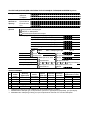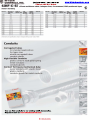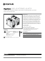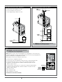
1
EESTI ENERGIA TEHNOLOOGIATÖÖSTUS AS Postal address Malmi 8, 41537 Jõhvi, ESTONIA Reg.code 10633284 [email protected] www.enefit.com Eesti Energia Õlitööstus AS Auvere küla, Vaivara vald, 40101, Ida-Viru maakond Tel 716 7296, faks 716 7034, [email protected] РАБОЧИЙ ПРОЕКТ ЭЛЕКТРИЧЕСКАЯ ЧАСТЬ Номер работы: JR5009 Töö nimetus: Проект подключения ENEFIT 280 к фусовым линиям КЕК-В,Г Ehitise aadress: Ida-Viru maakond, Vaivara vald, Auvere küla Разработчики: Liina Are ………… Руководитель проекта: Alexey Fedulov ………… JÕHVI 2015 ПРОЕКТНЫЕ ДАННЫЕ ДЛЯ ОБОГРЕВА ТРУБОПРОВОДОВ ГРЕЮЩИМ КАБЕЛЕМ Raychem Телефакс от Фирма Фамилия Телефакс Eesti Energia Tehnoloogiatööstus AS А.Федулов Общие данные по проекту Заказчик Проект/место Исполнитель Тел. Eesti Energia Õlitööstus AS Enefit 280 А.Скороходова .+3725533891 Проектные данные Назначение: Поддержание температуры Защ ита от замерзания Противоконденсационный нагрев Температура Требуемая температура продукта 60 °С Температура окр. среды -35 +25 °С Норм. технологическая температура* 60 °С Макс. технологическая температура** 190 °С Макс. допустимая температура продукта 200 °С Мин. температура включения*** Пропарка: Да 40 °С Макс. температура пара Нет 190 °С Напряжение 220 В Иное В Размещение Помещ ение Открытая площ адка Теплоизоляция Минеральная вата Иное Классификация зоны Нормальная Взрывоопасная Класс температуры Т1 Материал трубы Углеродистая сталь Пластмасса Т2 Т3 Т4 Т5 Каменная вата Т6 Невзрывоопасна Нержавеющ ая сталь Иной ТРУБОПРОВОДЫ ОбознаТолщина Диаметр Длина Задвижки Фланцы № чение тепло(кол-во) трубы (мм) трубы (м) (кол-во) линии изоляции 100 270 1 эстакада 48 + 48 100 78 2 помещение48 + 48 48 100 5 5 10 3 помещение 4 5 Кабель для поддержания температуры 6 Трубные опроры (приложить эскиз) Кол-во Размеры 70 20 4 * Температура продукта при нормальных эксплуатационных условиях. ** Макимальная температура, которой может достигать трубопровод (например, при пропарке). *** Минимальная температура воздуха, при которой может включиться система обогрева. Eesti Energia Tehnoloogiatööstus AS Malmi 8, Jõhvi,41537Eesti reg.nr. 10633284 MTR TEL001659 Sisukord: I II III Seletuskiri 1.1 Peamised tehnilised näitajad Lehekülg 3 1.2 Küttekaabli paigaldus 3 1.3 Elektritoite ühendamine 3 1.4 Kaablite paigaldus 3 1.5 Ohutustehnika 4 1.6 Elektripaigaldise hooldus ja ekspluatatsioon 4 Graafiline osa Küttekaablite ühendusskeemid Leht Formaat 5009.000.EE.001 А3 Kaablite ja torustike plaanid 5009.000.EE.002 А3 Lisad: Rayshem küttekaablid VPL Rayshem NGC-40-HTC/NGC-40-HTC3 Rayshem JBU100 Kaablid SIHF-C-SI End seal lighted E-100-L2-E Tööprojekt :Eesti Energia Õlitööstus AS.Auvere küla, Vaivara vald, 40101, Ida Viru maakond. TÖÖPROJEKT ; töö nr. JR5009; Eesti Energia Tehnoloogiatööstus AS, reg.nr 10633284; MTR TEL001659; INB Elektriinsener L. Are. Jagu 1 2 3 4 Лист 1/5 Eesti Energia Tehnoloogiatööstus AS Malmi 8, Jõhvi,41537Eesti reg.nr. 10633284 MTR TEL001659 I SELETUSKIRI Üldnäitajad 1. Projekt on koostatud dokumendi « Проектные данные для обогрева трубопроводов греющим кaбелем» Projektlahendused vastavad kehtivate reeglite ja direktiivmaterjalide nõudmistele. Projekteerimisel on kasutatud järgmisi norme ja reegleid: EVS 811-1:2012 Hoone ehitusprojekt. RTI, 09.11.2004,75,525 „Ehitisele ja selle osale esitatavad tuleohutusnõuded”. RTI, 15.02.2007, „Elektriohutusseadus“. EVS-HD 60364. „Madalpingelised elektripaigaldised“. Erinevad asjakohased osad. EVS-EN 61140:2006 „Kaitse elektrilöögi eest. Ühisnõuded paigaldistele ja seadmetele“. EVS-EN 60439 „Madalpingelised aparaadikoosted“. Erinevad asjakohased osad. EVS-ED 60364_5_54_2011 „Maandus ja potentsiaaliühtlustus“. EVS-EN 50110-1:2013 „Elektripaigaldise käit”. Eesti Energia (0,4…20kV) võrgustandardid . Tööde käigus ja järgneva käivituse ajal juhinduda eeltoodud eeskirjadest ja seadustest. Juhul kui elektripaigaldise eri osade kohta tekivad küsimused, lähtuda normdokumentide järgmisest tähtsuse järjekorrast: 1. EV seadused 2. EV määrused 3. EV standardid 4. Euroopa standardid (EN-HD, EN jne) 5. IEC- või rahvusvahelised standardid (SFS, DIN, ГОСТ jne). Kui erinevate üksikjuhtumite lahendamisel tekib ebakõla (vastuolu) eri normdokumentides esitatud nõudmiste vahel, siis tasub lähtuda nõudmisest, mis esitab antud probleemi lahendamisele kõrgendatud tingimusi. Tööprojekt :Eesti Energia Õlitööstus AS.Auvere küla, Vaivara vald, 40101, Ida Viru maakond. TÖÖPROJEKT ; töö nr. JR5009; Eesti Energia Tehnoloogiatööstus AS, reg.nr 10633284; MTR TEL001659; INB Elektriinsener L. Are. Лист 2/5 Eesti Energia Tehnoloogiatööstus AS Malmi 8, Jõhvi,41537Eesti reg.nr. 10633284 MTR TEL001659 1.1 PEAMISED TEHNILISED NÄITAJAD: Elektrivarustussüsteem Liitumispunkt Pinge Peakaitse TN-S; sektsioon Un In 10, 3x400V, 50 Hz. 3x80A; kaitsmed gG; 1.2 Küttekaablite paigutus Torustiku kütte on vajalik tehnoloogilise protsessi toimimiseks. Selleks peab õli temperatuur olema 600C.Maksimaalne temperatuur torustikus võib tõusta kuni 1900C.Küttekaabli lülimistemperatuur on 400C. Tehnilised parametrid on välja toodud dokumendis « Проектные данные для обогрева трубопроводов греющим кaбелем» Küttekaabel kinnitatakse torustikule vastavalt juhendile. Küttekaabli paigaldus on ette nähtud kahes suunas : pikem osa 284 m – kaabliga 10VPL4-CM kummalegi torule ja lühem osa 74 m kaabliga 5VPL2-CM ja 13m kaabliga 5VPL-CM. . 1.3 Elektritoite ühendamine Küttekaablite elektritoide tagatakse Kondensatsiooni osakonnas asuvast RP kilbist 10 sektsioonist , kasutatakse kolme vaba gruppi FB148/QA148 ; FB149/QA149; FB150/QA150 kaitse1X16A ja lisaks sisustatakse 2 uut gruppi kaitse 3X25A. Tellitavad lisaseadmed nr nimetus 1 Automaatkaitselüliti 2 Rikkevoolukaitse 3 Kontaktor 4 Modul tüüp S203 25A F204 25A 30mA ESB63-40 NGC-40-HTC3 Tööprojekt :Eesti Energia Õlitööstus AS.Auvere küla, Vaivara vald, 40101, Ida Viru maakond. TÖÖPROJEKT ; töö nr. JR5009; Eesti Energia Tehnoloogiatööstus AS, reg.nr 10633284; MTR TEL001659; INB Elektriinsener L. Are. kogus 2 2 2 2 Лист 3/5 Eesti Energia Tehnoloogiatööstus AS Malmi 8, Jõhvi,41537Eesti reg.nr. 10633284 MTR TEL001659 1.4 Kaablite paigaldus Kaablid skeemil näidatud skemaatiliselt, pikkus täpsustatakse montazi käigus . Kilbiruumist – torustikuni paigaldada toitekaablid osaliselt kaabliredelitel, osaliselt kaablikanalis. Toitekaablid tuua välja ühte punkti torustikul, kus toimub küttekaablitega ühendamine. Toitekaabel 13m osale (kaabel 5.) –kinnitada tõmmitsatega pikki torustiku isolatsiooni peal. Tabel 1. jrk nr Kaabli number Kaabli mark Kaabli ristlõige Elektritarviti SIHF-C-Si 4x4 mm2 2 SIHF-C-Si 2 4x4 mm 1.JBS-100-L-E 2.JBS-100-L-E 3 SIHF-C-Si 2x4 mm2 3.JBS-100-L-E 4 SIHF-C-Si 2x4 mm2 SIHF-C-Si 2 4.JBS-100-L-E 5.JBS-100-L-E 1. 2. 3. 1 4. 5. 5 2x4 mm Kui jääb puudu ruumist kaablite sisseviimiseks hoonesse, näha ette uute avade tekitamine peakilbihoonesse ning lisametallkonstruktsioonide paigaldus (kaabliredelid, püsttoed, harundid jms). Kaablite paigaldamise järel TAASTADA seinakatted (k.a tulekindlad materjalid). Metallkonstruktsioonide, nende hulk ja paigaldamise kõrgus kooskõlastada TELLIJAGA kohapeal. 1.5 Ohutustehnika Tööde teostamise ajal tuleb juhinduda TKK Tallinna keskuse kinnitatud kehtivatest sätetest ja vastavatest eeskirjadest. Enne elektriseadmete sisselülitamist tuleb üle kontrollida toitekaabli isolatsiooni korrasolek, soonemurdude puudumine, maanduse korrasolek. Kui seadmete sisselülitamisel lülitub kaitse välja, ei viida korduslülitust läbi enne rikke põhjuse väljaselgitamist ja kõrvaldamist elektriala personali poolt. Hoolduse ohutuse huvides peab elektrivõrkude remont toimuma pingetus olekus. Selle eesmärgi nimel peavad olema ette nähtud väljalülitamisaparaadi. Elektritööriistad, teisaldatavad elektrivalgustid kontrollitakse üle hoolsa välisvaatluse teel. Tähelepanu pööratakse maanduse ja juhtmete isolatsiooni korrasolekule, voolujuhtuvate paljasosade puudumisele. Elektritööriista ühendamiseks peab kasutama vasest kiudsoontega paindkaablit pingeisolatsiooniga mitte vähem kui 500 V. Elektritööriistade või teisaldatavate elektrivalgustite kasutamisel tuleb kaablid üles riputada. Tööprojekt :Eesti Energia Õlitööstus AS.Auvere küla, Vaivara vald, 40101, Ida Viru maakond. TÖÖPROJEKT ; töö nr. JR5009; Eesti Energia Tehnoloogiatööstus AS, reg.nr 10633284; MTR TEL001659; INB Elektriinsener L. Are. Лист 4/5 Eesti Energia Tehnoloogiatööstus AS Malmi 8, Jõhvi,41537Eesti reg.nr. 10633284 MTR TEL001659 Juhtmete ja kaablite vahetu kokkupuude kuumade, niiskete või õliste metallpindadega ei ole lubatud. Mis tahes defektide ilmnemisel tuleb töö elektritööriistade ja teisaldatavate vagustitega katkestada. Tööd elektritööriistadega kõrgendatud ohuga ruumis (voolujuhtivad põrandad, niiskus) tuleb teha kontrollitud ja kehtiva kõlblikkusajaga dielektrilistes kinnastes. 1.6 Elektripaigaldise hooldus ja ekspluatatsioon Enne elektripaigaldise töösseviimist mõõta ära kõikide uute paigaldatud kaablite isolatsioonitakistus. Ekspluatatsiooni käigus tuleb üks kord viie aasta jooksul viia läbi isolatsiooni takistuse mõõtmised, takistus peab olema vähemalt 1,0 MΏ. Perioodiliselt viia läbi juhtmete ja kaablite välisvaatlus. Elektriseadmed isolatsiooni takistusega alla 1,0 MΏ ning kuivanud isolatsiooniga juhtmed kuuluvad väljavahetamisele. Tööprojekt :Eesti Energia Õlitööstus AS.Auvere küla, Vaivara vald, 40101, Ida Viru maakond. TÖÖPROJEKT ; töö nr. JR5009; Eesti Energia Tehnoloogiatööstus AS, reg.nr 10633284; MTR TEL001659; INB Elektriinsener L. Are. Лист 5/5 EESTI ENERGIA EESTI ENERGIA ~HI-TECH ~ CONTROLS, INC. SiHF·C·Si www. h itech controls .com (800) 677·8942 I (303) 680·5159 Click or Call for a Quotel silicon multicore cable, halogen-free, cu-screened, EMC-preferred type, meter marking ~ ME01 RoHS Technical data Cable structure Properties • Special silicone-insulated cable with higher heat-resistance adapted to DIN VDE 0250 part 1 and part 816 • Temperature range -60 oc to +180 oc (+220 oc for short time> • Temperature limit at the conductor in operation +180 oc • Nominal voltage Uo/U 300/500 v • Test voltage 2000 v • Breakdown voltage min. 5000 v • Insulation resistance min. 200 MOhm x km • Power rating at ambient temperatures up to +145 oc according to DIN VDE 0100 150 oc- load value 100% 155 oc - load value 91% 160 oc- load value 82% 165 oc - load value 71% 170 oc - load value 58% 175 oc - load value 41% • Minimum bending radius flexing 10x cable 0 fixed installation 5x cable 0 • coupling resistance max. 250 Ohm/km • Radiation resistance up to 20x106 cJ/kg Cup to 20 Mrad> • Tinned copper conductor f ine w ire according to DIN VDE 0295 cl. 5, BS 6360 cl. 5 and IEC 60228 cl. 5 • Core insulation of silicone • Core colours according DIN VDE 0293-308 Core colour - up to 5 cores one-coloured - up 6 and more cores. black with white numbering - 3 and above. with green-yellow earth core - 2 cores without green-yellow earth core • cores stranded in layers with optimal lay-length • Inner sheath of silicone • Braid of tinned Cu wires, coverage approx. 85% • Silicone-rubber-insulated common outer jacket • Jacket preferentially redbrown colour • with meter marking, change-over in 2011 • Resistant to High molecular oils. fats f rom vegetables and animals, alcohols, plasticizers and clophenes. diluted acids. lyes and salt dissolution. oxidation substances. t ropical influences and weather. lake water. oxygen and uv • Halogen-free according to VDE 0482 part 267I DIN EN 50267-2-2/ IEC 60754-2 (equivalent DIN VDE 0472 part 813) • Burning behaviour no propagation of fire testing according to VDE 0482-332-1-2, DIN EN 60332-1 -2/ IEC 60332-1 Cequivalent DIN VDE 0472 part 804 test method B> • For laying as a f ixed installation only in open or ventilated pipe systems as well as in ducts. Otherwise the mechanical properties of the silicon are reduced by t he enclosed air at temperatures exceeding 90 °C. Note • G =with green-yellow earth core; x =without green-yellow earth core. • AWG sizes are approximate equivalent values. The actual cross-section is in mm2 . • unscreened analoguetype: SiHF see page E 7 Application Silicone-rubber-insulated cables are used for all applications where the cable insulation is subjected to high temperature fluctuations. These cables are heat-resistant for continuous use at temperatures up to +180 oc. as well as for short periods of time at +220 oc. Silicone-rubber-insulated cables can also be used at low temperatures down to -60 oc because of t he excellent weathering resistance of the material. These cables are halogen-free and hence are particularly suitable for applications in iron and steel works, rolling mills. foundries, in aircraft construct ion and ship building, as well as in cement, glass and ceramic plants. Silicone-rubber-insulated cables have demonstrated proven applications in projector and high- power lighting f ixtures as well as all types of heating equipment. An interference-free transmission of signals and pulse is assured by t he high screening density. The ideal interference-protected silicone multicore f lexible cable for such applications as given above. EMC = Electromagnetic compatibillity To optimise the EMC features we recommend a large round contact of the copper braiding on both ends. CE= The product is conformed with t he EC Low-Voltage Directive 2006/95/EG. Part no. 23151 23152 23153 23154 23155 23156 23157 23158 23159 23291 No.cores x cross-sec. mm• 2 x0,5 3 G0.5 4 G0.5 5G0.5 7 G0.5 10 G 0,5 12 G 0.5 16 G 0,5 18 G 0.5 25 G 0,5 Outer lit approx. mm 8,0 8.3 9,1 9,9 10,9 12,8 13,5 15,1 15.9 18.5 Cop. w eight kg/ km 55.5 60,8 66.5 81,6 92,2 124,0 134,4 170,2 181,0 230,1 Weight appr o x. kg/ km 101,0 118.0 131,0 153.0 173,0 242,0 263,0 326,0 351,0 348.0 AWC·NO. 20 20 20 20 20 20 20 20 20 20 Part no. 23160 23161 23162 23163 23164 23165 23166 23167 23168 23292 No.cores x cross-sec. mm• 2 X 0,75 3 G 0.75 4 G 0,75 5 G 0,75 7 G 0,75 10 G 0.75 12 G 0,75 16 G 0 ,75 18 G 0,75 25 G 0.75 outer lit approx. mm 9,0 9.4 10,4 11,3 12.0 13.9 15,2 16,9 18,0 20,8 Cop. w e ight kg / km 61.4 69.1 86,7 95.2 113,3 165,2 180.3 212.2 282,1 297,4 weight approx. kg / km 124,0 136,0 159,0 180,0 212,0 306.0 333.0 418,0 453.0 468,0 AWC·NO. 18 18 18 18 18 18 18 18 18 18 Continuation • C HELUKABEL ~HI-TECH ~ CONTROLS, INC. SiHF-C-Si (800) 677·8942 I (303) 680·5159 Click or Call for a Quotel www. h itech controls .com silicon multicore cable, halogen-free. cu-screened, EMC-preferred type, meter marking Part no. No.cores x cross-sec. ~ ME01 outer 1!1 approx. mm 23169 23170 23171 23172 23173 23174 23175 23176 23177 23293 23178 23179 23180 23181 23182 23183 23184 23185 23186 23294 9.4 9.8 11.1 12.0 12,7 14,7 15,8 17.4 18.5 21,8 10,8 11.2 12.0 12,8 13.6 14,7 15,8 17,4 20,6 24,2 Cop. weight kg /km 66.7 86.2 96.8 108.3 141,2 190,0 209,8 251,8 297.4 329,0 87,7 103,5 131,7 148,5 193.4 268,5 298.4 362,3 394,0 488,2 Weight approx. kg/km 132.0 153.0 173.0 202,0 243.0 238,0 371.0 468.0 526.0 559,0 172,0 198.0 235.0 281,0 345,0 482,0 531,0 662,0 720,0 791,0 AWC·No. Part no. 17 17 17 17 17 17 17 17 17 17 16 16 16 16 16 16 16 16 16 16 14 14 14 14 14 12 12 20 10 10 8 6 4 Dimensions and specifications may be changed without prior notice. <RE01 > Conduits Corrugated tubes for standard applications for lager sizes scissile corrugated tubes conduit glands High flexible conduits plastic conduits with spiral spring metal conduits conduits glands Conduit for heavy mechanical duty metal conduits with plastic sheat plastic conduits conduits glands for metal conduits You can find conduits in our catalog Cable Accessories. Request it now at www.hitechcontrols.com C Outer" approx. mm HELUKABEL Self-Regulating Cables Power-Limiting Cables Mineral Insulated Cables JBS-100 Single-entry power connection with junction box Longline Heating Product Overview JBS-100-A The cold-applied core sealer does not require a heat gun or torch for installation, so no hot work permit is necessary. The silicone-free, noncuring sealant allows easy installation and re-entry for maintenance. JBS-100-L-E (Shown with light) JBS-100-E JBS-100-L-E* Engineered Products JBS-100-A, A6 JBS-100-L-A* JBS-100-EP JBS-100-L-EP* *Not for use with 480 V VPL 09/13 1/4 Appendixes EN-RaychemJBS100-DS-H56827 Technical Data Sheets THERMAL MANAGEMENT SOLUTIONS This kit has a junction box with two M25 threaded entries, an earthing plate and an external earthing stud. It is designed for use with armored power cables. Steam-Tracing Systems Description This kit has a junction box This kit has a junction box with one through hole. with two M25 threaded entries, one stopping plug and one plastic power cable gland. Heat-Trace Panels The kit contains all the necessary materials for a complete installation except for one pipe strap, which must be ordered separately. Control and Monitoring Compared with other systems, this connection kit significantly reduces installation time. The kit is offered in three versions, customized for local installation practices, and is also available with a plug-in LED light (-L) that indicates when power is supplied to the heating cable circuit. Snow and Ice Innovative spring clamp terminals provide fast installation and safe, reliable, maintenance-free operation. Tank Heating The JBS-100 integrates the functions of connection kits and insulation entries. The rugged stand protects the heating cable and allows for up to four inches (100 mm) of thermal insulation. RTB Tubing Bundles The JBS-100 kit is designed to connect power to a single Raychem brand BTV, QTVR, XTV, KTV, or VPL heating cable. It is approved by FM, CSA, PTB and IEx for use in hazardous locations. jbs-100 JBS-100-A, A6 JBS-100-L-A* JBS-100-E JBS-100-L-E* JBS-100-EP JBS-100-L-EP* 1 junction box with terminals 1 stand assembly 1 core sealer 1 green/yellow tube 1 M25 gland for power cable 8–17 mm in diameter 1 M25 stopping plug 1 light module (for -L only) 1 cable tie 1 junction box with terminals, earth continuity plate, and stud 1 stand assembly 1 core sealer 1 green/yellow tube 1 M25 stopping plug 1 light module (for -L only) 1 cable tie *Not for use with 480 V VPL Kit Contents Note: Order appropriate pipe strap separately (one per kit) 1 junction box with terminals 1 stand assembly 1 core sealer 1 green/yellow tube 1 light module (for -L only) 1 cable tie Approvals Hazardous Locations II 2G II 2D Ex e II Ex tD A21 IP66 Class I, Div. 2, Groups A, B, C, D(2) Class II, Div. 2, Groups E, F, G(2) Class III(2) -ws CLI, ZN1, AEx e II T(2) CLI, ZN1, AEx em II T(2) (for -L only) PTB 09 ATEX 1059U IECEx PTB 09.0037U PTB 09 ATEX 1059U IECEx PTB 09.0037U -ws (1) II 2G Ex emb II II 2D Ex tD mbD A21 IP66 Ex em II T(2) Ex e II T(2) -ws -ws Ex e II T(2) Ex em II T(2) (for -L only) 09-IEx-0004X Ex e IIC T* Gb Ex em IIC T* Gb 09-IEx-0004X Ex em IIC T* Gb Ex e IIC T* Gb 09-IEx-0004X Ex e IIC T* Gb Ex em IIC T* Gb IECEx (1) Except VPL For T-rating, see heating cable or design documentation JBS-100-A is IECEx certified for use with: BTV-CR/BTV-CT: IECEx BAS 06.0043X QTVR-CT: IECEx BAS 06.0045X XTV-CT: IECEx BAS 06.0044X KTV-CT: IECEx BAS 06.0046X VPL-CT: IECEx BAS 06.0048X (2) Dimensions JBS-100-A, A6 3.6 in (90 mm) JBS-100-E JBS-100-EP 4.7 in (120 mm) 4.7 in (120 mm) 4.7 in (120 mm) 2/4 EN-RaychemJBS100-DS-H56827 09/13 THERMAL MANAGEMENT SOLUTIONS JBS-100-E Power-Limiting Cables JBS-100-A, A6 JBS-100-EP Product Specifications BTV-CR, BTV-CT, QTVR-CT, XTV-CT, KTV-CT and VPL-CT Ingress protection NEMA 4X IP66 / IP67 IP66 / IP67 Entries 1 x 3/4 in 2 x M25 2 x M25 Minimum installation temperature –40°F (–40°C) –40°F (–40°C) –40°F (–40°C) Minimum ambient temperature –75°F (–60°C)* –60°F (–50°C)* –60°F (–50°C)* Maximum ambient temperature 132°F (56°C)* 132°F (56°C)* 132°F (56°C)* Mineral Insulated Cables Heating cable capability Terminals Spring clamp Ex e 2 line, 1 ground Spring clamp Ex e 1 phase, 1 neutral, 1 earth Spring clamp Ex e 1 phase, 1 neutral, 1 earth Maximum conductor size 8 AWG (A6 to 6 AWG) 10 mm2 10 mm2 Maximum operating voltage 480 Vac 480 Vac 480 Vac Maximum circuit breaker rating 50 A 40 A 40 A Enclosure Electrostatic chargeresistant glass-filled engineered polymer, black Electrostatic chargeresistant glass-filled engineered polymer, black Electrostatic chargeresistant glass-filled engineered polymer, black Lid screws Stainless steel Stainless steel Stainless steel Materials Lid gasket Silicone rubber Silicone rubber Silicone rubber Earth continuity plate n/a n/a Steel, zinc-plated and yellow-chromated Control and Monitoring Optional LED Indicator Light Red Green Green 100–277 Vac 100–277 Vac 100–277 Vac Power consumption <1W <1W <1W Catalog number JBS-100-A / JBS-100-A6 JBS-100-E JBS-100-EP Part number 085947-000 / C26470-000 829939-000 158251-000 Weight 2.5 lb (1.1 kg) 1.2 kg (2.6 lb) 1.3 kg (2.9 lb) Catalog number JBS-100-L-A JBS-100-L-E JBS-100-L-EP Part number 944699-000 054363-000 075249-000 Weight 3.5 lb (1.6 kg) 1.6 kg (3.5 lb) 1.7 kg (3.7 lb) Heat-Trace Panels Color Voltage rating Snow and Ice 500°F (260°C) Tank Heating 500°F (260°C) RTB Tubing Bundles 500°F (260°C) Longline Heating * For –L lighted kits, the ambient temperature range is –40°F (–40°C) to 104°F (40°C). For non-lighted kits, use a power wire with continuous temperature rating of > 194°F (90°C). For –E and –EP kits use a metallic power cable gland. Maximum pipe temperature Self-Regulating Cables jbs-100 Ordering Details Power connection Engineered Products Power connection with light Steam-Tracing Systems Technical Data Sheets EN-RaychemJBS100-DS-H56827 09/13 3/4 Appendixes THERMAL MANAGEMENT SOLUTIONS WWW.PENTAIRTHERMAL.COM NORTH AMERICA Europe, Middle East, Africa Asia Pacific Latin America Tel:+1.800.545.6258 Fax:+1.800.527.5703 Tel:+1.650.216.1526 Fax:+1.650.474.7711 [email protected] Tel:+32.16.213.511 Fax:+32.16.213.603 [email protected] Tel:+86.21.2412.1688 Fax:+86.21.5426.2917 [email protected] Tel:+1.713.868.4800 Fax:+1.713.868.2333 [email protected] Pentair, JBS, BTV, QTVR, XTV, KTV, and VPL are owned by Pentair or its global affiliates. All other trademarks are the property of their respective owners. Pentair reserves the right to change specifications without prior notice.. © 2000–2013 Pentair. THERMAL MANAGEMENT SOLUTIONS EN-RaychemJBS100-DS-H56827 09/13 4/4 NGC-40 Panel mounted advanced modular heat-tracing control system Product Overview Local configuration and monitoring with Raychem Touch 1500 touch screen display The Raychem NGC-40 is a multipoint electronic control, monitoring and power distribution system with a unique single-point controller architecture providing the most reliable central control and monitoring solution for your Heat Management System. By taking advantage of innovative modular packaging techniques, the Raychem NGC-40 system provides configuration and component flexibility so that it may be optimised for a customer’s project specific needs. Heat-tracing system NGC-40 system Control modules: NGC-40-HTC & NGC-40-HTC3 The Raychem NGC-40 uses a single controller module per heat-tracing circuit for maximum reliability. The Raychem NGC-40 control system can be powered between 100 to 240 Vac, while mechanical contactors (EMRs) or solid-state relays (SSRs) allow circuit switching up to 60 A at 600 Vac. HTC HTC3 There are dedicated control modules available for single phase (NGC-40-HTC) and three-phase (NGC-40-HTC3) heat-tracing circuits. The Raychem NGC-40 control modules include ground-fault detection and protection. The control modules guarantee precise single phase and three-phase line current measurements. Up to eight (8) temperature sensors (RTDs) can be used for each heat-tracing circuit allowing a variety of temperature control, monitoring, and alarming configurations. The Raychem NGC-40 provides alarm outputs and digital inputs. The alarm output can be used to control an external annunciator. The digital input is programmable and may be used for various functions such as forcing outputs on and off or generating alarms, making the system more flexible to match each customer’s specific needs. SIL2 Safety Temperature Limiter: NGC-40-SLIM The Raychem NGC-40 has a SIL2 certified safety temperature limiter module. The module can be used with up to 3 temperature inputs for three phase heattracing circuits. The limiter can be associated with a Raychem NGC-40 controller and use current information for latching the trip functionality. The front panel of the limiter module has LED indicators for various status conditions. The front panel also provides a button to confirm new set trip point, a reset trip button and a reset alarm button. The module has one output for the contactor and one output for external alarm annunciation. The safety temperature limiter can be reset via the digital input, the user interface Touch 1500 and Raychem Supervisor. INDUSTRIAL HEAT TRACING SOLUTIONS EN-RaychemNGC40-DS-DOC2210 Rev4 1/6 NGC-40 IO module: NGC-40-IO In addition to hardwiring an RTD directly into a Heat Trace Control module, RTDs can be wired to Input/output modules (NGC-40-IO) within the panel and assigned to heat-tracing circuits through software. This means that a Raychem NGC-40 system can be optimised for the specific application needs. Each IO module accepts up to four additional RTD inputs. RMM2 The Raychem NGC-40 works with the MONI-RMM2 module. Each RMM2 module installed in the field can accept up to 8 RTDs. 16 RMM2 Modules can be daisy chained together via RS-485 for a total of 128 temperature inputs. Since multiple RMM2s can be networked over a single cable to the Raychem NGC-40, the cost of RTD field wiring will be significantly reduced. Communication module: NGC-40-BRIDGE The Raychem NGC-40 system supports multiple communications ports, allowing serial interfaces (RS-485 and RS-232) and network connections (Ethernet) to be used with external devices. All communications with the NGC-40 panel are accomplished through the NGC-40-BRIDGE module which acts as the central router for the system, connecting the panel’s control modules, IO modules, safety limiter modules, RMM2 Modules, as well as upstream devices such as Raychem Touch 1500 touch screen, Raychem Supervisor (DTS) and Distributed Control System (DCS). Communications to devices external to the NGC-40 panel are done via Modbus® protocol over Ethernet, RS-485 or RS-232. Raychem Touch 1500 The Raychem NGC-40 system supports multiple communications ports, allowing serial interfaces (RS-485 and RS-232) and network connections (Ethernet) to be used with external devices. All communications with the NGC-40 panel are accomplished through the NGC-40-BRIDGE module which acts as the central router for the system, connecting the panel’s control modules, IO modules, safety limiter modules, RMM2 Modules, as well as upstream devices such as Raychem Touch 1500 touch screen, Raychem Supervisor (DTS) and Distributed Control System (DCS). Communications to devices external to the NGC-40 panel are done via Modbus® protocol over Ethernet, RS-485 or RS-232. Raychem Supervisor Software The Raychem Supervisor (DTS) software package provides a remote, graphic interface for the Raychem NGC-40. The software allows the user to configure and monitor various NGC systems from a central location. It also provides an audible alarm tone, acknowledges and clears alarms; and contains advanced features such as data logging, trending, implement changes in batches, and other useful functions. Users can access all information from anywhere in the world, making Raychem Supervisor a powerful management tool for the entire Heat Management System. 2/6 EN-RaychemNGC40-DS-DOC2210 Rev4 INDUSTRIAL HEAT TRACING SOLUTIONS NGC-40 General Raychem NGC-40 controller modules Application type The Raychem NGC-40 units shall be installed in non-hazardous areas. Hazardous area approved sensors shall be used when the system is applied to heat-tracing circuits in hazardous areas. Approval certification (Russia, Kazakhstan, Belarus) For other countries contact your local Pentair representative. ETL not for NGC-40-SLIM module Electromagnetic compatibility Emissions EN 61000-6-3 Immunity EN 61000-6-2 Supply voltage 24 Vdc +- 10% Internal power consumption < 2.4 W per module Ambient operating temperature –40ºC to 65ºC (–40ºF to 149ºF) Ambient storage temperature –40ºC to 75ºC (–40ºF to 167ºF) Environment PD2, CAT III Maximum altitude 2,000 m (6,562 ft) Humidity 5 – 90% non-condensing Mounting Din Rail – 35 mm CAN Networking Port Type Connection Topology Cable length Quantity Address 2-wire isolated CAN-based peer to peer network. Isolated to 24 Vdc – verified by 500 Vrms dielectric withstand test Two 8-pin RJ-45 connectors (both may be used for Input or Output connections) Protocol Proprietary NGC-40 Daisy chain 10 m (33 ft) maximum Up to 80 HTC/HTC3 and IO modules per network segment Unique, factory assigned Connection terminals and Housing Wiring terminals Spring-type, 0.5 to 2.5 mm2 (24 to 12 AWG) Housing Size 45.1 mm (1.78 in) wide x 87 mm (3.43 in) high x 106.4 mm (4.2 in) deep Module specific information NGC-40-HTC/NGC-40-HTC3 Temperature Sensors Type 100 Ω platinum RTD, 3-wire,α = 0.00385 ohms/ohm/ºC Can be extended with a 3-conductor shielded cable of 20 Ω maximum per conductor 100 Ω, Ni-Fe, 2-wire. Can be extended with a 2-wire shielded cable of 20 Ω maximum per conductor Quantity Temperature sensors One per NGC-40-HTC/HTC3 module Measuring range Temperature range from -80˚C to +700˚C (−112°F to 1292°F) Current measurement Internal to the module Current measurement NGC-40-HTC 1 for single-phase line current measurements, 60A, +/- 2% of range Current measurement NGC-40-HTC3 3 for three-phase line current measurements, 60A, +/- 2% of range Ground-fault 1 for ground-fault measurements, 10-250 mA, +/- 2% of range Alarm Relay Dry contact relay (voltage free). Relay contact rated 250 V/3 A 50/60 Hz (EC) and 277 V/3 A 50/60 Hz (cCSAus). Alarm relay is programmable. N0 and NC contacts available. Contactor Output Relay Relay contact rated 250 V/3 A 50/60 Hz (EC) and 277 V/3 A 50/60 Hz (cCSAus). SSR Output 12 Vdc @ 45 mA max per output Digital Input Multi-purpose input Multi-purpose input for connection to external dry (voltage-free) contact or DC voltage. May be user programmable for: not used/force off/force on functions. It can be configured to be active open or active closed. INDUSTRIAL HEAT TRACING SOLUTIONS EN-RaychemNGC40-DS-DOC2210 Rev4 3/6 NGC-40 NGC-40-SLIM Functional Safety Approval Conditions of use Measuring range Temperature Sensor Digital Input NGC-40-IO Temperature Sensors Quantity Temperature sensors Alarm Relay Digital Input Functional safety according to Baseefa10SR0109 SIL 2 IEC 61508-1-1998 & IEC 61508-2-2000 See installation instructions Temperature range limiter from +50˚C to +500˚C (-22˚F to 932˚F) Type: 100 Ω platinum RTD, 3-wire, α = 0.00385 ohms/ohm/˚C. Can be extended with a 3-conductor shielded cable of 20 Ω maximum per conductor. Quantity: 3 per NGC-40-SLIM module. Used for resetting the safety temperature limiter remotely. The Digital Input will be for connection to external dry (voltage free) contactor or DC voltage. The input shall be 5 – 24 VDC/1mA max with 100 ohms of loop resistance and configured as active low. Type 100 Ω platinum RTD, 3-wire,α = 0.00385 ohms/ohm/ºC Can be extended with a 3-conductor shielded cable of 20 Ω maximum per conductor 100 Ω, Ni-Fe, 2-wire. Can be extended with a 2-wire shielded cable of 20 Ω maximum per conductor. Up to four wired directly to each NGC-40-IO module Dry contact relay (voltage free). Relay contact rated 250 V/3 A 50/60 Hz (EC) and 277 V/3 A 50/60 Hz (cCSAus). Alarm relay is programmable. N0 and NC contacts available. Multi-purpose input Multi-purpose input for connection to external dry (voltage-free) contact or DC voltage. May be user programmable for: not used/force off/force on functions. It can be configured to be active open or active closed. NGC-40-BRIDGE Communications COM1, COM2 Type Cable Length Quantity Data rate Data bits Parity Stop bits Tx delay Protocol Connection terminals 2-wire RS-485 One shielded twisted pair 1,200 m (4,000 ft) maximum Up to 255 devices per port 9600, 19.2K, 38.4K, 57.6K, 115.2K baud 7 or 8 None, even, odd 0, 1, 2 0 – 5 sec. Modbus RTU or ASCII Spring-type terminals Communications COM3 Type Cable Length Data rate Data bits Parity Stop bits Tx delay Protocol Connection terminals RS-232 Custom TTC# 10332-005 15 m (50 ft) maximum 9600, 19.2K, 38.4K, 57.6K, 115.2K baud 7 or 8 None, even, odd 0, 1, 2 0 – 5 sec. Modbus RTU or ASCII RJ-11 Ethernet Type Length Data rates Protocol Connection terminals 10/100 BaseT Ethernet network 100 m (328 ft) 10 or 100 MB/s Connection terminals Shielded 8-pin RJ-45 connector on front of module 4/6 EN-RaychemNGC40-DS-DOC2210 Rev4 INDUSTRIAL HEAT TRACING SOLUTIONS NGC-40 NGC-40-PTM Connection terminals Spring-type, 0.5 to 2.5 mm2 (24 to 18 AWG). As the current to the modules require up to 2.05 A @ 24Vdc (20 modules - see CAN Bus connection diagrams) the minimum wire size to the module shall be 1.0 mm2 (AWG18) CAN networking and module Power Two RJ-45 connectors, one each IN and OUT. Provides CAN bus signals and 24 Vdc power. TOUCH 1500 General Area of use Supply voltage Amperage rating Surge current Operating temperature Storage temperature Dimensions Relay outputs Display Network Connection Local/Remote Port Remote RS-485 Field Port LAN USB Ports Nonhazardous, Indoors (IP65, NEMA 4) 10 – 30 Vdc Steady state 1.8 A 16 A 0°C to 50°C (32°F to 122°F) w/o space heater, –30°C to 50°C (–22°F to 122°F) using space heater and screen cover –20°C to 60°C (–4°F to 140°F) 449.9 mm ( W) X 315.6 mm (H) X 141.7 mm (D) One Form C relay rated at 12 A @ 250 Vac. Relay is used as a common alarm. To be ordered separately LCD is a 15-in XGA, color TFT transflective device with integral CCFL backlight Touch Screen 4-wire resistive touch screen interface for user entry RS-232/RS-485 ports may be used to communicate with host (Raychem Supervisor Software) or DCS 9 pin D sub male 2-wire isolated, 9 pin D sub male Data rate 9600 to 57600 baud Maximum cable length not to exceed 1200 m (4000 ft). Cable length to be shielded, twisted pair. RS-485, 2-wire isolated, used for communication with external devices, such as Raychem NGC-40-BRIDGE and Raychem NGC-20. Maximum cable length not to exceed 1200 m (4000 ft). Cable to be shielded twisted pair. Signals 2-wire isolated, 9 pin D sub male Data rate to 9600 baud 10/100 Base-T Ethernet port with Link and Activity Status LEDs (X2) USB 2.0 Host port Type A receptacle (X4) Part numbers Product name Description Part Number NGC-40-HTC NGC-40 single phase heat trace control module 10730-003 NGC-40-HTC3 NGC-40 three phase heat trace control module 10730-004 NGC-40-SLIM NGC-40 Safety Temperature Limiter 1244-010700 NGC-40-IO NGC-40 Input - Output Module 10730-001 NGC-40-BRIDGE NGC-40 Communication Bridge Module 10730-002 NGC-40-PTM NGC-40 Power Termination Module 10730-005 TOUCH1500 TOUCH1500 display kit– 15" Touch screen and Relay Output Module 10332-009 TOUCH1500R Touch 1500 in enclosure for remote mounting on wall 10332-020 RELAY OUTPUT - TOUCH Relay Output Module /w Modbus for Touch 1500 10332-017 NGC-40-CAN05 NGC-40 CAN Cable Length 5" 20578011-005 NGC-40-CAN48 NGC-40 CAN Cable Length 48" 20578011-048 NGC-40-TB CANbus termination plug 10392-043 PS-24 24 Vdc Power supply 972049-000 INDUSTRIAL HEAT TRACING SOLUTIONS EN-RaychemNGC40-DS-DOC2210 Rev4 5/6 WWW.PENTAIRTHERMAL.com Europe, Middle East, Africa United Kingdom Ireland Tel: +32.16.213.511 Fax: +32.16.213.603 [email protected] Tel: 0800 969 013 Fax: 0800 968 6241 [email protected] Tel: 1800 654 241 Fax: 1800 654 240 [email protected] All Pentair trademarks and logos are owned by Pentair or its global affiliates. Pentair reserves the right to change specifications without prior notice. © 1998-2014 Pentair. INDUSTRIAL HEAT TRACING SOLUTIONS EN-RaychemNGC40-DS-DOC2210 Rev4 6/6 NGC-40-HTC/NGC-40-HTC3 Control and monitoring modules for use with the Raychem NGC-40 system Installation Instructions Description A The NGC-40-HTC (for single-phase heaters) and NGC-40-HTC3 (for three-phase heaters) modules are used to control either a solid-state relay or contactor within the NGC-40 control and monitoring system. This module also has one alarm output and one digital input. The alarm output can be used to control an external annunciator. The digital input is programmable and may be used for various functions such as forcing outputs on and off. Other features of this module include ground-fault and line current sensing for both HTC and HTC3. The front panel of the HTC module has LED indicators for various status conditions. The front panel also provides a ground-fault and heater test button. B HTC or HTC3 Additional Materials Required • Power supply 24 Vdc @100 mA per NGC-40-HTC/HTC3 • Custom built CAN cables with RJ-45 connections • CAN Termination Resistor Approvals Hazardous Locations Class I, Div. 2, Groups A,B,C,D T4 Class I, Zone 2, AEx nC IIC T4 IP20 Ex nL nC IIC T4 X –40˚C ≤ Ta ≤ +65˚C Tools Required • Small flat-blade screwdriver Conforms to: FM Class Number 3600 (11/98) FM Class Number 3611 (10/99) ANSI/UL STD. 60079-15-2009 UL STD. 61010-1 Certified to: CAN/CSA STD. C22.2 No. 213-M1987 (R2004) CAN/CSA STD. C22.2 No. 61010-1:2004 EN 61010-1 (2001) CAN/CSA STD. E60079-15:02 (R2006) Kit Contents ItemQty Description A 1 NGC-40-HTC module (single-phase heaters) 1 NGC-40-HTC3 module (three-phase heaters) or (Russia, Kazakhstan, Belarus) For other countries contact your local Pentair representative. B WARNING: This component is an electrical device that must be installed correctly to ensure proper operation and to prevent shock or fire. INDUSTRIAL HEAT TRACING SOLUTIONS For technical support, call Pentair at (800) 545-6258. EN-RaychemNGC40HTC-IM-H58087 12/14 1 / 10 General Supply voltage Internal power consumption Ambient operating temperature Ambient storage temperature Environment Max. altitude Humidity Mounting 24 Vdc ± 10% < 2.4 W per NGC-40-HTC/HTC3 module –40ºC to 65ºC (–40ºF to 149ºF) –40ºC to 75ºC (–40ºF to 167ºF) PD2, CAT III 2,000 m (6,562 ft) 5 – 90% noncondensing Din Rail – 35 mm Electromagnetic Compatibility Emissions EN 61000-6-3 Emission standard for residential, commercial and light industrial environments EN 61000-6-2 Immunity standard for industrial environments Immunity Temperature Sensors Type 100 Ω platinum RTD, 3-wire, α = 0.00385 ohms/ohm/ºC Can be extended with a 3-conductor shielded cable of 20 Ω maximum per conductor 100 Ω, Ni-Fe, 2-wire Can be extended with a 2-wire shielded cable of 20 Ω maximum per conductor One per NGC-40-HTC/HTC3 module Quantity Current Sensors (internal to the module) Quantity per NGC-40-HTC/HTC3 Quantity per NGC-40-HTC Quantity per NGC-40-HTC3 Maximum Line - Line Voltage: Alarm Relay Dry contact relay (voltage free) Contactor Output Relay Digital Input Multi-purpose input CAN Networking Port Type Connection Protocol Topology Cable length Quantity Address Connection Terminals Wiring terminals Housing Size Line Current Sensors Max current Accuracy Ground-Fault Sensor Range Accuracy Outputs SSR output INDUSTRIAL HEAT TRACING SOLUTIONS 1 for ground-fault measurements 1 for single-phase line current measurements 3 for three-phase line current measurements 1000 Vac Relay contact rated 250 V / 3 A 50/60 Hz (CE) and 277 V / 3 A 50/60 Hz (c-CSA-us). Alarm relay is programmable. NO and NC contacts available. Relay contact rated 250 V / 3 A 50/60 Hz (CE) and 277 V / 3 A 50/60 Hz (c-CSA-us). Multi-purpose input for connection to external dry (voltage-free) contact or DC voltage. May be user programmable for: not used / force off / force on functions. It can be configured to be active open or active closed. 2-wire isolated CAN-based peer to peer network. Isolated to 24 Vdc – verified by 500 Vrms dielectric withstand test Two 8-pin RJ-45 connectors (both may be used for Input or Output connections) Proprietary NGC-40 Daisy chain 10 m (33 ft) maximum Up to 80 HTC/HTC3 and IO modules per network segment Unique, factory assigned Cage clamp, 0.5 to 2.5 mm2 (24 to 12 AWG) 45.1 mm (1.78 in) wide x 87 mm (3.43 in) high x 106.4 mm (4.2 in) deep 60 A ± 2% of reading 10 – 250 mA ± 2% of range 12 Vdc @ 45 mA max per output EN-RaychemNGC40HTC-IM-H58087 12/14 2 / 10 System Components 45.1 mm (1.78 in) HTC 45.1 mm (1.78 in) 45.1 mm (1.78 in) 45.1 mm (1.78 in) Front HTC3 87 mm (3.43 in) 87 mm (3.43 in) 106.4 mm (4.2 in) 1PH Top Bottom 45.1 mm (1.78 in) 45.1 mm (1.78 in) Back 45.1 mm (1.78 in) 45.1 mm (1.78 in) Front Top 87 mm (3.43 in) 87 mm (3.43 in) 106.4 mm (4.2 in) 3PH Bottom Back System Components (Continued) A. Wiring terminals TerminalsFunction 1 Alarm relay N.O. 2 Alarm relay COM 3 Alarm relay N.C. 4 Not used 5 SSR Out + 6 SSR Out – 7 Digital In + 8 Digital In – 9 Line In 10 Line Out 11 Coil Out 12 13 TS COM (Wht) 14 TS Sense (Red) 15 TS Source (Red) 16 Not used WARNING: Shock Hazard. Disconnect from live voltage prior to accessing terminals INDUSTRIAL HEAT TRACING SOLUTIONS B. CAN bus/module power Output: C. Reset D. Status LEDs Status: Indicates status of HTC/HTC3 module Off No power Green Normal operation, no internal faults Yellow In Factory mode Red HTC/HTC3 operating status Flash R Internal Fault: Flash R/G Factory status Flash R/Y Internal fault detected Network: Indicates CAN network activity Off Green Yellow Flash R Input: Off Green Flash R No network activity Flicker on receipt of network data Flicker on transmission of network data Network communication failure Shows status of digital input Input is inactive (open) Input is active (shorted) Ext. input source failure EN-RaychemNGC40HTC-IM-H58087 12/14 Off Green Heater: Off Red Flash R TS: Off Red Flash R GFI: Off Red Flash R Switch: Off Red Flash R Shows status of contactor or SSR Output off Follows output state Indicates the heater's alarm status No alarm High or low current or resistance alarm Overcurrent trip alarm Indicates the temperature alarm status No alarm High or low temperature alarm Temperature sensor failure Indicates ground-fault status No alarm High or low ground-fault alarm Ground-fault trip alarm Indicates contactor/SSR switch status No alarm Contactor cycle count alarm Switch failed shorted on 3 / 10 Mounting the NGC-40-HTC/HTC3 Each NGC-40-HTC/HTC3 mounts on a DIN 35 rail. Mounting: Insert the rear bottom of the module into the DIN rail, then push up and inwards to engage the clip. Removal: Push the module upwards to disengage the clip, then rotate the module toward you. 2 2 1 1 Power Supply/CAN The power supply/CAN connector is an RJ-45 connector. The CAN termination device must be installed in the unused port of the last module. Connections are the same for the HTC3. HTC Cable from another module or power supply CAN termination here if last one in chain RTD Input Connections – North American Installation Technique For all RTD terminations, the RTD field wires must be terminated on a panel-mounted terminal block. HTC Connections are the same for the HTC3. 1PH 13 - T.S. COM (Wht) 14 - T.S. Sense (Red) 15 - T.S. Source (Red) 16 - Not used HTC RTD Wiring 13 14 15 16 Terminal block RTD INDUSTRIAL HEAT TRACING SOLUTIONS EN-RaychemNGC40HTC-IM-H58087 12/14 4 / 10 RTD Input Connections – European Installation Technique For all RTD terminations, the RTD field wires must be terminated on a panel-mounted terminal block. The RTD cable shield from the field terminal block to the HTC module should be terminated at the earth ground bar located near the module. HTC 13 - T.S. COM (Wht) 14 - T.S. Sense (Red) 15 - T.S. Source (Red) 16 - Not used 1PH Connections are the same for the HTC3. HTC RTD Wiring Earth grounding bar located at the HTC module 13 14 15 16 Field terminal block RTD HTC Relay Output Connections to Contactors - Single-Phase HTC3 Relay Output to Contactor - Three-Phase Terminals 9 and 11 switch voltage to the contactor coils. The internal pilot relay will switch the supply voltage (up to 277 V) to the contactor coil. Refer to the diagram at the end of this document called “NGC-40 CAN bus Connections for Up to 10 Modules” for detail wiring. Note: Exposure to some chemicals may degrade the sealing properties of the relay output, manufactured by NAIS, PN JQ1P-12V. Periodically inspect the relay output for degradation of properties and replace if any degradation is found. HTC3 Three-Phase L3 L1 Connections are the same for the HTC3. L2 N Circuit breaker 11 9 Contactor To heattracing L1 N or L2 11 Coil Out 9 contactor N or L2 L1 (in) Control power contactor coil WARNING: Shock Hazard. Disconnect from live voltage prior to accessing terminals. INDUSTRIAL HEAT TRACING SOLUTIONS L3 To heattracing Contactor coil Coil out N or L2 Control L1 (in) power L1 L2 N WARNING: Shock Hazard. Disconnect from live voltage prior to accessing terminals. EN-RaychemNGC40HTC-IM-H58087 12/14 5 / 10 HTC Output Connections to SSR - Single-Phase HTC3 Output Connections to SSR - Three-Phase Terminals 5 & 6 switch voltage to the SSR. The internal SSR driver will switch the internal supply voltage (12 Vdc) to the SSR. HTC Single-Phase HTC HTC3 Three-Phase L3 L1 L2 HTC Circuit breaker 13 N - T.S. COM (Wht) 14 - T.S. Sense (Red) 15 - T.S. Source (Red) 16 - Not used 1PH N or L2 HTC RTD Wiring L3 L1 L1 Earth grounding bar located at the HTC module N L2 13 14 15 16 Circuit breaker H 3P Field terminal block RTD 6 5 H 1P L1 L1 L2 L1 6 N or L2 12 Vdc + ~ To heattracing To heattracing 5 SSR L2 L3 – ~ L3 N or L2 ~ ~ SSR ~ ~ SSR ~ ~ SSR + – + – + – N L1 WARNING: Shock Hazard. Disconnect from live voltage prior to accessing terminals. Alarm WARNING: Shock Hazard. Disconnect from live voltage prior to accessing terminals. Note: Exposure to some chemicals may degrade the sealing properties of the alarm relay, manufactured by NAIS, PN JQ1P-12V. Periodically inspect the alarm relay for degradation of properties and replace if any degradation is found. 1PH Multi-purpose. Alarm relay energized in normal state. The alarm relay is configured as Fail Safe. The alarm relay connections provide a form C dry contact, rated at 277 V max (3 A). The NO (normally open) contact is open in non-energized condition. When energized, it closes during normal conditions and will open upon an alarm condition or power failure. The NC (normally closed) contact is closed in non-energized condition. When energized, it opens during normal conditions and will close upon an alarm condition or power failure. Relay contact rated 250 V / 3A 50/60 Hz (CE) 277 V / 3A 50/60 Hz (c-CSA-us) Alarm Relay 1 2 Failsafe Mode: Contacts shown NO C energized with no alarm condition 3 NC HTC Connections are the same for the HTC3. INDUSTRIAL HEAT TRACING SOLUTIONS EN-RaychemNGC40HTC-IM-H58087 12/14 6 / 10 Digital Input Connections – North American and European Installation Techniques Digital Input Multi-purpose input for connection to external dry (voltage free) contact or DC voltage. Rating 100 Ω max loop resistance or 5-24 Vdc @ 1mA maximum Connections are the same for the HTC3. North American Installations European Installations 1PH 1PH 7 + 7 8 8 + – – Terminal block Terminal block + Earth grounding bar located at the HTC module Digital Input Digital Input + – – From user input From user input HTC HTC Provide Suitable Panel Enclosure and Determine Locations for NGC-40-HTC or NGC-40-HTC3 Assembly in Panel* HTC9 HTC10 C10 HTC20 HTC19 HTC29 C30 C5 C20 HTC28 HTC30 I/O3 I/O4 I/O5 HTC8 HTC7 C8 C9 C18 C19 HTC27 C28 HTC18 I/O1 I/O2 C29 HTC17 HTC6 HTC5 HTC4 C5 C6 C7 HTC16 HTC26 HTC15 HTC25 C27 HTC14 HTC24 C25 C16 PS1 CBM C26 C17 HTC2 HTC3 C4 C3 HTC12 HTC13 C24 C113 HTC22 HTC23 C23 C4 HTC1 PTM2 C1 PS3 C11 C12 PTM3 C2 PS2 The NGC-40-HTC or NGC-40-HTC3 should be located in the rear of the panel. The NGC-40-HTC or NGC-40-HTC3 assembly is an electronic unit and must not be located where it will be exposed to strong magnetic fields or excessive vibration. PS4 2. Determine locations for the NGC-40-HTC or NGC-40HTC3 assembly in the electrical panel. HTC11 Alarm light PTM1 Panel PTM4 Note: The Raychem NGC-40-HTC or NGC-40-HTC3 is designed for operation in ambient temperatures from –40°C to 65°C (–40°F to 149°F). If the ambient temperature is outside this range, a space heater and/or cooling fan will be required in the panel. Panel door HTC21 The NGC-40-HTC or NGC-40-HTC3 must be mounted in an enclosure to protect its electronic components. For indoor applications, use a minimum NEMA 1 enclosure (NEMA 12 recommended). For outdoor applications, use a NEMA 4 or NEMA 4X enclosure depending on the requirements. C21 C22 1.Provide suitable panel enclosure TB * North American panel installation techniques INDUSTRIAL HEAT TRACING SOLUTIONS EN-RaychemNGC40HTC-IM-H58087 12/14 7 / 10 NGC-40 CAN Bus Connections for Up to 10 Modules Termination Block CAN / 24 Vdc CAN / 24 Vdc CAN / 24 Vdc CAN / 24 Vdc Termination Block CAN / 24 Vdc CAN/Term CAN / 24 Vdc Power/ Termination Module IN Primary Supply* 24 Vdc 20 Modules per Power Supply + Redundant Supply* 24 Vdc – IN 20 Modules per Power Supply OUT IN OUT IN OUT IN OUT CAN / 24 Vdc CAN / 24 Vdc CAN / 24 Vdc CAN / 24 Vdc Bridge Module HTC/HTC3 or I/O HTC/HTC3 or I/O HTC/HTC3 or I/O HTC/HTC3 or I/O Module 2 Module 3 Module 4 Module 10 80 Modules per Bridge 100-240 Vac In 100-240 Vac In OUT CAN / 24 Vdc Module 1 + – Optional redundant supply * Power supply shall have a means for dicsonnect from line voltage NGC-40 CAN Bus Connections for Up to 20 Modules Termination Block CAN / 24 Vdc CAN / 24 Vdc CAN / 24 Vdc CAN / 24 Vdc CAN / 24 Vdc CAN/Term CAN / 24 Vdc Power/ Termination Module + – 20 Modules per Power Supply OUT OUT IN OUT IN OUT IN OUT CAN / 24 Vdc CAN / 24 Vdc CAN / 24 Vdc Bridge Module HTC/HTC3 or I/O HTC/HTC3 or I/O HTC/HTC3 or I/O HTC/HTC3 or I/O Module 2 Module 3 Module 4 Module 10 80 Modules per Bridge Redundant Supply* 24 Vdc IN CAN / 24 Vdc 100-240 Vac In 100-240 Vac In Primary Supply* 24 Vdc IN CAN / 24 Vdc Module 1 + – 20 Modules per Power Supply Optional redundant supply CAN / 24 Vdc CAN / 24 Vdc Power/ Termination Module CAN / 24 Vdc IN OUT IN CAN / 24 Vdc OUT IN CAN / 24 Vdc OUT IN Termination Block CAN / 24 Vdc OUT IN OUT CAN / 24 Vdc CAN / 24 Vdc CAN / 24 Vdc CAN / 24 Vdc CAN / 24 Vdc HTC/HTC3 or I/O HTC/HTC3 or I/O HTC/HTC3 or I/O HTC/HTC3 or I/O HTC/HTC3 or I/O Module 11 Module 12 Module 13 Module 14 Module 20 * Power supply shall have a means for disconnect from line voltage INDUSTRIAL HEAT TRACING SOLUTIONS EN-RaychemNGC40HTC-IM-H58087 12/14 8 / 10 NGC-40 CAN Bus Connections for Up to 40 Modules Termination Block CAN / 24 Vdc CAN / 24 Vdc CAN / 24 Vdc CAN / 24 Vdc CAN / 24 Vdc CAN/Term CAN / 24 Vdc Power/ Termination Module 100-240 Vac In IN + 20 Modules – per Power Supply IN OUT IN OUT IN OUT IN OUT CAN / 24 Vdc CAN / 24 Vdc CAN / 24 Vdc CAN / 24 Vdc Bridge Module HTC/HTC3 or I/O HTC/HTC3 or I/O HTC/HTC3 or I/O HTC/HTC3 or I/O Module 2 Module 3 Module 4 Module 10 80 Modules per Bridge 100-240 Vac In Primary Supply* 24 Vdc OUT CAN / 24 Vdc Module 1 Redundant Supply* 24 Vdc + 20 Modules – per Power Supply Optional redundant supply CAN / 24 Vdc CAN / 24 Vdc CAN / 24 Vdc CAN / 24 Vdc CAN / 24 Vdc CAN / 24 Vdc CAN/Term CAN / 24 Vdc Power/ Termination Module IN OUT IN OUT IN OUT IN OUT IN OUT CAN / 24 Vdc CAN / 24 Vdc CAN / 24 Vdc CAN / 24 Vdc CAN / 24 Vdc Bridge Module HTC/HTC3 or I/O HTC/HTC3 or I/O HTC/HTC3 or I/O HTC/HTC3 or I/O Module 12 Module 13 Module 14 Module 20 80 Modules per Bridge Module 11 CAN / 24 Vdc CAN / 24 Vdc CAN / 24 Vdc CAN / 24 Vdc CAN / 24 Vdc CAN / 24 Vdc CAN/Term CAN / 24 Vdc Power/ Termination Module 100-240 Vac In Primary Supply* 24 Vdc + 20 Modules – per Power Supply IN OUT IN OUT IN OUT IN OUT IN OUT CAN / 24 Vdc CAN / 24 Vdc CAN / 24 Vdc CAN / 24 Vdc CAN / 24 Vdc HTC/HTC3 or I/O HTC/HTC3 or I/O HTC/HTC3 or I/O HTC/HTC3 or I/O HTC/HTC3) or I/O Module 21 Module 22 Module 23 Module 24 Module 30 100-240 Vac In Redundant Supply* 24 Vdc + 20 Modules – per Power Supply Optional redundant supply CAN / 24 Vdc CAN / 24 Vdc CAN / 24 Vdc CAN / 24 Vdc CAN / 24 Vdc Termination Block CAN / 24 Vdc CAN/Term CAN / 24 Vdc Power/ Termination Module IN OUT IN OUT IN OUT IN OUT IN OUT CAN / 24 Vdc CAN / 24 Vdc CAN / 24 Vdc CAN / 24 Vdc CAN / 24 Vdc HTC/HTC3 or I/O HTC/HTC3 or I/O HTC/HTC3 or I/O HTC/HTC3 or I/O HTC/HTC3 or I/O Module 31 Module 32 Module 33 Module 34 Module 40 * Power supply shall have a means for disconnect from line voltage INDUSTRIAL HEAT TRACING SOLUTIONS EN-RaychemNGC40HTC-IM-H58087 12/14 9 / 10 Servicing The NGC-40-HTC/HTC3 contains no user serviceable parts. Contact your Pentair representative for service and an RMA number if required. WARNING: Explosion Hazard - Substitution of AVERTISSEMENT - Risque D'explosion - La substitution WARNING: Explosion Hazard - Do not replace NGC-40- AVERTISSEMENT - Risque D'explosion - Couper le WARNING: Explosion Hazard - Do not disconnect AVERTISSEMENT - Risque D'explosion - Avant de components may impair suitability for Class I, Division 2 hazardous and nonhazardous locations PTM unless power has been switched off or the area is known to be nonhazardous equipment unless power has been switched off or the area is known to be nonhazardous de composants peut rendre ce matériel inacceptable pour les emplacements de Classe I, Division 2 courant ou s'assurer que l'emplacement est désigné non dangereux avant de replacer le NGC-40-PTM déconnecter l'equipement, couper le courant ou s'assurer que l'emplacement est désigné non dangereux WWW.PENTAIRthermal.COM NORTH AMERICA Europe, Middle East, Africa Asia Pacific Latin America Tel: +1.800.545.6258 Fax: +1.800.527.5703 Tel: +1.650.216.1526 Fax: +1.650.474.7711 [email protected] Tel: +32.16.213.511 Fax: +32.16.213.603 [email protected] Tel: +86.21.2412.1688 Fax: +86.21.5426.2917 [email protected] Tel: +1.713.868.4800 Fax: +1.713.868.2333 [email protected] All Pentair trademarks and logos are owned by Pentair or its global affiliates. Pentair reserves the right to change specifications without prior notice. © 2007-2014 Pentair. INDUSTRIAL HEAT TRACING SOLUTIONS EN-RaychemNGC40HTC-IM-H58087 PCN 1244-009548 12/14 10 / 10 Guide d’installation et d’entretien Traçage Électrique Rubans Chauffants Autorégulants et à Puissance Limitante Thermal management solutions FR-RaychemSelfRegCable-IM-DOC72-R10 1 2 3 4 5 6 7 8 9 10 11 Information générale Pg. 1 Sélection du ruban chauffant Pg. 3 Installation du ruban chauffant Pg. 4 Installation des accessoires Pg. 13 Thermostats de contrôle Pg. 18 Calorifugeage et marquage Pg. 19 Alimentation et protection électrique Pg. 21 Essai du ruban chauffant Pg. 21 Fonctionnement du ruban, entretien et réparations des tuyauteries Pg. 23 Ruban chauffant endommagé Pg. 24 Guide de recherche de défauts Pg. 24 1 Information générale Utilisation du guide Ce guide est conçu uniquement pour l’installation et l’entretien des rubans chauffants autorégulants et à puissance limitante Pentair Thermal Management sur canalisations et réservoirs calorifugés. Pour toute information relative à d’autres applications, veuillez contacter votre agent Pentair Thermal Management. BTV, QTVR, KTV & XTV Rubans Chauffants Auto-régulants Phase Neutre La puissance varie avec la température. Quand la température de tuyauterie augmente, la puissance de sortie diminue. A hautes températures, le polymère se dilate en réduisant ainsi le nombre de chemins électriques diminuant alors le passage du courant. A basses températures, le nombre de chemins électriques se multiplie permettant le passage du courant entre les éléments conducteurs. VPL Rubans Chauffants à Puissance Limitante Phase Neutre Important Pour que la garantie Pentair Thermal Management s’applique, les instructions données dans ce guide ainsi que les notices d’installation particulières fournies avec les composants, doivent être suivies rigoureusement. L’installation du ruban chauffant doit être conforme aux normes en vigueur applicables aux systèmes de traçage électrique. 1 Conditions d’utilisation sans risque: voir certification zone explosible. BASEEFA Certification N° BTV: Code Baseefa06ATEX0183X II 2 GD Ex e II T6 Ex tD A21 IP66 QTVR: Baseefa06ATEX0185X II 2 GD Ex e II T4 Ex tD A21 IP66 XTV: Baseefa06ATEX0184X II 2 GD Ex e II T* Ex tD A21 IP66 KTV: Baseefa06ATEX0186X II 2 GD Ex e II 226°C (T2) Ex tD A21 IP66 VPL: Baseefa06ATEX0188X II 2 GD Ex e II T* Ex tD A21 IP66 *: Pour plus d’informations, voir le protocole d’agrément pour zone explosible. PTB Certification N° BTV: Code PTB 98 ATEX 1102 X II 2 G/D EEx e(m) II T6 IP66 T80°C QTVR: PTB 98 ATEX 1103 X II 2 G/D EEx e(m) II T4 IP66 T130°C KTV: PTB 98 ATEX 1104 X II 2 G/D EEx e(m) II T4/T3/226°C(T2) IP66 T130°C, T195°C, T226°C XTV: PTB 98 ATEX 1105 X II 2 G/D EEx e(m) II T4/T3/250°C(T2) IP66 T130°C, T195°C, T250°C IEC Ex Certification N° Code BTV: Ex e II T6 / Ex tD A21 IP66 IECEx BAS 06.0043X QTVR: IECEx BAS 06.0045X Ex e II T4 / Ex tD A21 IP66 XTV: IECEx BAS 06.0044X Ex e II T* / Ex tD A21 IP66 KTV: IECEx BAS 06.0046X Ex e II 226°C (T2) / Ex tD A21 IP66 VPL: IECEx BAS 06.0048X Ex e II T* / Ex tD A21 IP66 *: Pour plus d’informations, voir le protocole d’agrément pour zone explosible. Tension nominale: BASEEFA BTV1, QTVR1, KTV1, XTV1, VPL1: 110V, 120V BTV2, QTVR2, KTV2, XTV2, VPL2: 230V, 277V, VPL4: 400V, 480V PTB BTV2, QTVR2, KTV2, XTV2: 230V, 254V Rayon de courbure minimum à 20°C à –60°C Température d’installation minimum BTV QTVR XTV-T3 XTV-T2 KTV VPL 15 mm 50 mm 15 mm 50 mm 15 mm 50 mm 15 mm 50 mm 25 mm 50 mm 20 mm 20 mm –60°C –60°C –60°C –60°C –60°C –60°C Température de maintien maximum (sous tension) 65°C 110°C 120°C 120°C 150°C Siehe Tabelle unten Température d’exposition maximum (1000 heures d’exposition cumulée sous tension) 85°C 110°C 215°C 215°C 215°C – Température d’exposition maximum (hors tension continue) – – – – – Température autolimitante suivant EN 62086-1 5.1.11 T6 T4 T3 T2 T2 T* Température de puissance limitante (*Sur spécification) - - - - - T* 2 260°C Tableau de température de maintien maximum (sous tension) Cable 110 V 230 V 254 V 277 V 400 V 480 V 5VPL1-CT 235°C ----10VPL1-CT 215°C ----15VPL1-CT 190°C ----20VPL1-CT 150°C ----5VPL2-CT - 230°C225°C225°C- - 10VPL2-CT - 210°C200°C195°C- - 15VPL2-CT - 180°C155°C105°C- - 20VPL2-CT -150°C ---5VPL4-CT ----230°C 230°C 10VPL4-CT ----205°C 205°C 15VPL4-CT ----160°C 160°C 20VPL4-CT ----150°C 150°C Attention Comme pour tout équipement ou câblage électrique sous tension, une installation incorrecte ainsi que tout dommage causé au ruban ou à ses composants, permettant la pénétration d’humidité ou de contamination, peuvent provoquer un cheminement électrique, un court-circuit et un risque de feu. Ne pas connecter ensemble les deux conducteurs ; ceci créerait un court-circuit. Toute extrémité de câble non connectée doit être isolée avec la terminaison Pentair Thermal Management appropriée. Pour prévenir les risques d’incendie et d’explosion en zone explosible, vérifier que la température maximale de la gaine du ruban chauffant est inférieure au point d’inflammation des gaz présents. Pour plus d’informations, voir la documentation. 2 Sélection du ruban chauffant S’assurer que le ruban à installer a bien été sélectionné en fonction de la spécification. Se référer aux documents techniques de produits, tables de calcul et logiciel TraceCalc de Pentair Thermal Management pour choisir le ruban chauffant adapté à l’environnement thermique, chimique, électrique et mécanique. 3 3 Installation du ruban chauffant 3.1Stockage du ruban Entreposer le ruban chauffant dans un endroit propre et sec. Plage de température : –40°C à +60°C. Protéger le ruban chauffant de tout dommage mécanique. 3.2 Vérification avant installation Vérification du matériel reçu?: S’assurer que le matériel expédié est conforme à la commande et à la dernière offre technique Pentair Thermal Management en vérifiant le numéro de référence des rubans et des composants. La référence du ruban est marquée sur la gaine extérieure. La température d’exposition du ruban installé ne doit pas dépasser celle spécifiée dans la fiche technique relative à ce produit. Tout dépassement de température dégraderait les performances du ruban. S’assurer que la température prévue reste bien dans la plage spécifiée. S’assurer que la tension du ruban est compatible avec la tension de service disponible sur le site. Contrôler l’aspect du matériel reçu (ruban chauffant et accessoires) pour détecter tout incident lié au transport. Un test de mesure de résistance d’isolement sur chaque touret est conseillé (voir paragraphe 8). Vérification des tuyauteries à tracer : 4 S’assurer du bon résultat des épreuves hydrauliques. Parcourir le cheminement du ruban chauffant sur la tuyauterie et localiser les emplacements des composants le long de celle-ci. Vérifier la conformité de l’installation des tuyauteries aux isométriques de la spécification. En cas de différence, consulter la personne responsable (bureau d’études). S’assurer que les tuyauteries ne comportent pas de bavures, surfaces rugueuses ou arêtes vives qui puissent endommager le ruban. Ebavurer ou couvrir celles-ci avec du ruban fibre de verre ou aluminium. 3.3Manipulation du ruban chauffant Recommandations : Les revêtements et peinture de la tuyauterie doivent être secs au toucher avant l’installation du ruban chauffant. En déroulant le ruban, éviter: Les arêtes vives Une tension excessive Toute torsion ou écrasement De marcher, rouler ou déposer toute charge dessus Quelques conseils pour dérouler le ruban chaufffant : Placer le touret sur un support qui permet de réduire la tension au déroulement. Tirer le ruban chauffant de façon lâche et proche de la tuyauterie en évitant les interférences avec les supports ou équipements. Dérouler la longueur de ruban prévue et marquer la limite de câble, toujours en bobine, avec du ruban adhésif par exemple. Laisser une longueur additionnelle de ruban de 50 cm environ à chaque emplacement d’alimentation, jonction en ligne, dérivation ou terminaison. Prévoir les longueurs supplémentaires de ruban pour tracer les déperditions propres aux supports, vannes et brides ou pour spiraler si nécessaire selon la spécification de traçage. Protéger toutes les extrémités du ruban de l’humidité, de toute contamination ainsi que des accidents mécaniques ou autres s’il doit rester exposé sans être utilisé avant la mise en place des composants définitifs. 3.4 Mise en place du ruban chauffant Le ruban chauffant peut être posé linéairement (un ou plusieurs rubans) ou spiralé selon les spécifications de l’étude technique ou la documentation de produit Pentair Thermal Management. Ne pas utiliser d’attaches métalliques, de ruban adhésif vinyl ou autre car ils peuvent endommager le ruban. La technologie de l’auto-régulation autorise le chevauchement multiple du câble chauffant sur lui-même. La technologie de la puissance limitante impose que le câble chauffant ne se chevauche qu’une seule fois. 5 Pour le ruban VPL uniquement : Mettre le ruban en place en le fixant soit à l’aide du ruban adhésif en fibre de verre approprié en respectant au minimum deux tours soit à l’aide de colliers de serrage tous les 300 mm ou moins si nécessaire. Les colliers de serrage en plastique doivent pouvoir supporter les températures des tuyauteries. Ne pas dépasser le rayon de courbure minimum du ruban (voir p. 2). Plier le câble seulement dans le sens de la longueur Bend the cable only in upright position Le câble chauffant ne peut se plier facilement dans l’axe plan. Ne jamais plier un câble ainsi, car celui-ci pourrait être endommagé 3.4.1 Traçage linéaire Tracer la tuyauterie en linéaire sauf si l’étude technique prévoit le spiralage (voir paragraphe 3.4.2). Pour les tuyauteries horizontales, poser le ruban comme indiqué sur la figure 1, et non le long de la génératriceinférieure. Pour éviter la surchauffe, s’assurer que le ruban à puissance limitante est placé de telle manière que la zone chauffante active ne s’étende pas dans le composant. Consulter les instructions d’installation et prévoir l’emplacement des composants avant de fixer définitivement le ruban sur la canalisation. S’assurer que les zones chauffantes actives se trouvent aux endroits à chauffer, à savoir sur la canalisation. 6 Calorifuger et protéger selon les spécifications. Figure 1 300 mm Haut Tuyauterie Ruban adhésif en fibre de verre Fixé sur la tuyauterie Calorifuge idem 45° (nominal) Ruban adhésif Pentair Thermal Management : GT-66 Ruban adhésif en fibre de verre. GS-54 Ruban adhésif en fibre de verre. Pour des tuyauteries en acier indoxydable et pour des applications à haute température. Figure 2 ATE-180 Ruban adhésif aluminiumA utiliser uniquement si spécifié. L’ATE-180 améliore le transfert thermique. Fixer le ruban chauffant sur la tuyauterie comme indiqué sur la figure 2. 7 3.4.2. Spiral tracing Deux méthodes de spiralage sont présentées : figures 2a et 2b. Ne spiraler le ruban que sur les tuyauteries spécifiées dans les études d’engineering. Pour éviter la surchauffe, s’assurer que le ruban à puissance limitante est placé de telle manière que la zone chauffante active ne s’étende pas dans le composant. Consulter les instructions d’installation et prévoir l’emplacement des composants avant de fixer définitivement le ruban sur la canalisation. S’assurer que les zones chauffantes actives se trouvent aux endroits à chauffer, à savoir sur la canalisation. Tableau de pas de spiralage (mm). NB IPS Facteur de spiralage (mm) (pouces) (mètres de ruban par mètre de tuyauterie) 1.1 1.2 1.3 1.4 1.5 25 1 250 170 140 110 100 32 11/4 310 210 170 140 130 40 11/2 350 240 190 160 140 50 2 430 300 240 200 180 65 21/2 520 360 290 240 210 80 3 630 430 350 290 260 90 31/2 720 490 390 330 290 100 4 800 560 440 370 330 125 5 990 680 550 460 400 150 6 1180 810 650 550 480 200 8 1520 1050 840 710 620 Exemple : Pour une tuyauterie de DN 80 (3”) nécessitant 1,3 mètres de ruban par mètre de tuyauterie, le pas de spiralage est de 350 mm. Figure 2a Longueur de la tuyauterie Ruban adhésif fibre de verre Ruban chauffant Fixer du ruban adhésif avant spiralage Tuyauterie Pas Enrouler en sens inverse Longueur du ruban chauffant 8 Fixer avec le ruban adhésif après enroulement du ruban Longueur du ruban chauffant = Longueur de la tuyauterie X facteur de spiralage Pour le facteur de spiralage, se référer aux calculs de dimensionnement. Etape 1 Préparer la première boucle. Etape 2 Enrouler la boucle autour de la tuyauterie. Etape 3 Espacer régulièrement et fixer sur la tuyauterie. Calorifuger et protéger selon les spécifications. Figure 2b Ruban adhésif fibre de verre Ruban chauffant autorégulant Pas Tuyauterie Se référer aux calculs de dimensionnement pour le facteur de spiralage. Marquer la tuyauterie à la valeur du pas de spiralage ou utiliser un mètre Fixer le ruban chauffant au fur et à mesure de l’installation. Calorifuger et protéger selon les spécifications. 3.5 Coupe du ruban chauffant Couper le ruban chauffant après l’avoir fixé à la tuyauterie, en s’assurant que les longueurs supplémentaires mentionnées au paragraphe 3 ont été prévues. La puissance au mètre est indépendante de la longueur de coupe. 3.6Détails d’une installation type Les détails d’installation du ruban chauffant sur la tuyauterie sont présentés ci-après. Remarques générales : L’installation du ruban est prévue pour faciliter toute intervention ultérieure. Consulter les spécifications de dimensionnement pour mettre en place le ruban autour des supports. Pour couper et dénuder les rubans chauffants, suivre les recommandations du guide d’installation des composants. 9 3.6.1 Vanne Figure 3 Tuyauterie Corps de vanne Ruban chauffant Ruban adhésif en fibre de verre (type) Ce dessin illustre la méthode classi-que d’installation. La configuration de l’installation peut varier en fonction du type de vanne ou des longueurs de ruban chauffant. Se référer à la spécification pour la taille de la boucle. Fixer avec du ruban adhésif en fibre de verre. Calorifuger et protéger selon les spécifications. 3.6.2 Coude Figure 4 Tuyauterie Ruban adhésif en fibre de verre Ruban chauffant Calorifuge 10 Installer le ruban chauffant sur la génératrice extérieure du coude. Fixer avec du ruban adhésif en fibre de verre. Calorifuger et protéger selon les spécifications. 3.6.3 Bride Figure 5 Tuyauterie Ruban adhésif en fibre de verre Ruban chauffant La longueur de ruban chauffant supplémentaire est égale à 2 fois la circonférence de la tuyauterie + 1 fois le diamètre du jeu de bride. Fixer avec du ruban adhésif en fibre de verre. Calorifuger et protéger selon les spécifications. 3.6.4 Support suspendu Figure 6 Tige de suspension Joint d’étanchéité Tôle de protection Tuyauterie Ruban chauffant Tige de suspension Joint d’étanchéité Ruban adhésif en fibre de verre (type) Ruban chauffant 11 Ne pas pincer le ruban avec le collier. Le poser par dessus. Aucune longueur de ruban supplémentaire n’est nécessaire pour ce type de support. Fixer avec le ruban adhésif en fibre de verre. Calorifuger et protéger selon les spécifications. 3.6.5 Support patin soudé Figure 7 Vue de côté Ruban en fibre de verre Support patin Tuyauterie Vue de dessous Ruban chauffant 12 Tuyauterie Consulter Pentair Thermal Management pour déterminer la taille de la boucle. Fixer avec le ruban adhésif en fibre de verre. Calorifuger et protéger selon les spécifications. 4 Installation des accessoires Généralités : Utiliser le catalogue technique pour choisir les composants nécessaires. Les composants Raychem (y compris boîtes de jonction, jonctions en ligne et terminaisons) doivent être utilisés afin de satisfaire aux normes électriques en vigueur et d’être conforme aux agréments requis dans les atmosphères explosibles. Pour dénuder correctement le ruban et pour une installation satisfaisante des composants, suivre attentivement les instructions fournies avec les kits. Les rubans chauffants autorégulants et à puissance limitante Raychem sont des circuits parallèles. Ne pas connecter ensemble les conducteurs ; cela créerait un court-circuit. 4.1 Composants nécessaires Nécessaires pour chaque longueur de ruban :Boîte de jonction et kit d’entrée de calorifugeKit de terminaison Et selon les cas :Kit de jonction en ligneKit de dérivation (Té) : boîte de jonction, 3 kits de connexion, 3 kits d’entrée de calorifugeAccessoires (colliers de fixation, ruban adhésif, supports de boîte, étiquettes, etc.) 13 4.2Système type Figure 8a Valve SB-100 JBU-100 Ruban chauffant Terminaison 14 Montage mural IEK-25-04 Entrée de calorifuge JBU-100 Boîte de raccordement pour système modulaire C25-100 Kit de connexion Heating cable Jonction en ligne Calorifuge Ruban adhésif Entrée de calorifuge SB-101 Thermostat Se référer à la spécification pour la taille des boucles. Fixer avec du ruban adhésif en fibre de verre. Calorifuger et protéger selon les spécifications (y compris les vannes.) 15 Figure 8b JBM-100 Kit de raccordement intégré T-100 Jonction ou dérivation JBS-100 Kit de raccordement intégré (représenté ici avec témoin lumineux) C-150 Kit d’alimentation plat IEK-25-04 Kit d’entrée de calorifuge 16 E-100-L Terminaison à témoin lumineux E-100 End seal S-150 Jonction en ligne sous calorifuge E-150 Terminaison sous calorifuge 17 4.3 Méthode d’installation des composants Pour les tuyauteries horizontales, placer les boîtes de jonction sous la tuyauterie si possible. Placer les boîtes de jonction de manière à en faciliter l’accès mais sans les exposer aux chocs. Placer les boîtes de jonction de manière à ce que les entrées de câble d’alimentation électrique et de ruban chauffant ne soient pas dirigées vers le haut. Placer les couvercles aux endroits où l’accès n’est pas nécessaire. Vérifier que les bouchons d’obturation de la boîte de jonction correspondent à leur utilisation et sont bien fixés. Tirer le ruban chauffant de la boîte de jonction à l’entrée de calorifuge de manière à éviter des dommages éventuels. Laisser du jeu dans la connexion en cas d’éventuels réparations. Le surplus de ruban doit être enroulé autour de la tuyauterie. Ne pas tendre le ruban aux entrées/sorties des boîtes de jonction et de calorifuge. Vérifier que le ruban chauffant est fixé au-dessus des colliers de fixation utilisés par exemple pour les supports de boîtes de jonction. Fixer avec du ruban adhésif en fibre de verre tous les composants installés sous le calorifuge. 5 Thermostats de contrôle 18 Pour certains produits thermosensibles, un contrôle thermostatique peut s’avérer nécessaire (température maximale à ne pas dépasser). Dans ce cas, utiliser le guide d’installation du thermostat. Suivre la procédure d’installation fournie avec le thermostat. Bien s’assurer que les branchements réalisés correspondent au mode de fonctionnement souhaité. 6 Calorifugeage et marquage 6.1 Vérifications avant calorifugeage S’assurer visuellement que l’installation du ruban et des composants est correcte et que ceux-ci n’ont subi aucun dommage (voir paragraphe 10 si dommage.) Le contrôle de la résistance d’isolement (Mégohmmètre) est recommandé avant de recouvrir la tuyauterie avec l’isolant thermique (voir paragraphe 8.) 6.2Conseils pour la pose du calorifuge Un maintien en température correct nécessite un calorifugeage bien installé et sec. Utiliser scrupuleusement le type et l’épaisseur de calorifuge ainsi que la tôle de protection préconisés dans la spécification d’étude. Se reporter éventuellement à la documentation Pentair Thermal Management. Pour réduire le risque d’endommagement éventuel sur le ruban, poser le calorifuge aussitôt après l’installation et la vérification du ruban chauffant. Vérifier que toute la tuyauterie, les brides, les traversées de paroi et autres surfaces ont été entièrement calorifugées. S’assurer que le ruban n’a pas subi de dommage lors de la pose de la tôle de protection dû, par exemple, aux vis de fixation, aux flasques latérales ou arêtes tranchantes. Vérifier que toutes les entrées de calorifuge sont installées correctement et parfaitement étanches. S’assurer que toutes les découpes de calorifuge sont étanches ; par exemple sur les vannes, supports, sondes de thermostats, etc. 19 6.3Marquage Pour les rubans chauffants à puissance limitante VPL, placer l’étiquette LAB-I-35 comme illustré sur les figures 9a & 9b ci-dessous. Figure 9a 0 60 d se 0 0 II ergifnen öf S -1 x e U ile en ng ion J B 2 G EE 1058 en whannutens X II ATEX t op r Spsous 02 no te ir 10 .D. 199X B 97 Do t unouvr -95 PT s Ex 96D3 X Nich pa 03 B Nr.. Ex 10 Ne PTS No .D. 8X R BA T6 II C V de T6 BT EEX e II x T4 EE II C VR de T4 QT EEX e II x ) T2 (T2 EE II C6°C V de 22 3 KT EEX e II V-T x EE 15XT C T3 , 12 II 8, de T3 4, EEX e II x EE 2 C T2 (T2) C V-T II XT de 0° 20 EEX e II 25 x EE 19 -95 Ex 96D3 Ex X 04 B Nr.. 10 PTS No .D. 200X BA -95 Ex 96D3 X 05 B Nr. . Ex 10 PTS No .D. 435X BA -95 Ex 96D3 X 05 B Nr.. Ex 10 PTS No .D. 5X 47 BA -95 43 16 Ex 95D3 55 PR B Nr.. Ex PTS No BA LAB-I-35 Figure 9b LAB-I-35 20 Placer les étiquettes “Traçage électrique” de chaque côté le long de la tuyauterie calorifugée. Prévoir une étiquette tous les 3 mètres de part et d’autre pour une bonne signalisation. Indiquer sur la tôle de protection du calorifuge l’emplacement des accessoires tels que les extrémités de ruban. 7 Alimentation et protection électrique 7.1 Tension La protection électrique doit être conforme aux spécifications de l’étude ou de la documentation Pentair Thermal Management (Guide de calcul). En cas d’utilisation d’autres systèmes, consulter le représentant Pentair Thermal Management pour vérifier la compatibilité. 7.2 Protection différentielle Pentair Thermal Management insiste sur l’utilisation d’un différentiel de 30mA afin d’assurer une sécurité et une protection maximales. L’utilisation d’un tel type de protection est exigée pour l’approbation des installations de rubans chauffants électriques en zones explosibles. 8 Essai du ruban chauffant 8.1Recommandations Pentair Thermal Management recommande de vérifier la résistance d’isolement : • avant d’installer le câble chauffant, • avant d’installer le calorifuge, • avant la première mise en service, • et pour l’entretien périodique (voir paragraphe 9.2). 8.2 Procédure de test Après l’installation complète du ruban chauffant, un contrôle d’isolement devra être fait à l’aide d’un Mégohm-mètre sous 2500 VDC (Figure 10). Les lectures minimales doivent être de 10 mégohms indépendamment de la longueur du ruban. L’installateur doit noter les valeurs initiales pour chaque circuit sur la feuille d’installation (voir page 25). 21 Figure 10 Test: entre les fils conducteurs du ruban et la tresse. 22 9 Fonctionnement du ruban, entretien et réparations des tuyauteries 9.1Fonctionnement du ruban chauffant La température d’exposition ne doit pas dépasser celle spécifiée dans la documentation Pentair Thermal Management du produit. Dépasser les limites, c’est raccourcir la durée de vie du ruban et risquer d’endommager de façon permanente le ruban. Le calorifuge doit être complet et sec pour maintenir à la bonne température. 9.2Inspection périodique Inspecter visuellement et périodiquement le ruban chauffant et le calorifugeage pour s’assurer qu’il n’y a aucun dommage mécanique. Contrôler régulièrement la résistance d’isolement. Les installations mises hors gel doivent être vérifiées chaque année avant l’hiver (voir paragraphe 8). Dans le cas de maintien en température, une vérification doit avoir lieu deux fois par an. Vérifier régulièrement le bon fonctionnement des protections et des thermostats. 9.3Entretien et réparations des tuyauteries Au cours des opérations d’entretien de chaque circuit, la fiche d’inspection périodique devra être remplie. Déconnecter le ruban chauffant et le protéger de toute agression mécanique ou thermique pendant les travaux de réparation de tuyauterie. Vérifier l’installation du ruban chauffant après réparation de la tuyauterie et remettre le calorifuge en place selon les recommandations du paragraphe 6. S’assurer du bon fonctionnement des protections électriques. 23 10 Ruban chauffant endommagé Ne pas réparer le ruban endommagé. Sectionner la partie endommagée et la remplacer par une longueur identique de ruban en utilisant les kits de jonction Raychem appropriés. Remplacer immédiatement le ruban endommagé. Un ruban endommagé peut entraîner une pénétration d’humidité ou de contamination, et provoquer un court-circuit et un risque de feu. Un ruban chauffant exposé au feu ou aux flammes peut créer un incendie si on le met sous tension. Le remplacer immédiatement. 11 Guide de recherche de défauts 24 Se reporter au guide pages 28 à 31. Si le problème persiste après avoir suivi les procédures du guide, contacter immédiatement le représentant Pentair Thermal Management. 25 REMARQUES ET COMMENTAIRES: Repérage extérieur des composants sous calorifuge Calorifugeage terminé et posé Tension du circuit Test au mégohmmètre après calorifugeage (débrancher le thermostat). Test au mégohmmètre avant pose du calorifuge (débrancher le thermostat). Numéro du plan Numéro du disjoncteur INSTALLATION DE : Date Initial Date Opérateur Connection terminals Panel Date Opérateur Lecture Date Opérateur Lecture uit circ du No. FICHE D’INSTALLATION Thermostats correctement réglés et capillaires protégés Connexions : Presse-étoupe, rubans et câbles d’alimentations serrés Date Opérateur Date Opérateur Date Pas de signes d’humidité, de corrosion Opérateur ou de surchauffe. VERIFICATION DE : MOINS : FICHE D’INSPECTION ET DE MAINTENANCE uit circ du No. 26 ANNEE : 27 REMARQUES ET COMMENTAIRES: Repérage extérieur des composants sous calorifuge Boîtes de jonction et thermostats clos hermétiquement Tension du circuit Test au mégohmmètre (débrancher le thermostat) Date Opérateur Date Opérateur Borniers de connexion Armoire électrique Date Opérateur Lecture Guide de dépannage ASymptôme : Déclenchement des protections électriques standard (fusibles). Causes possibles 1 Défaut électrique : a ruban chauffant endommagé b mauvaise jonction en ligne ou dérivation c mauvaise terminaison d mauvaise connexion 2 Circuit surdimensionné 3 Démarrage en-dessous de la température limite définie 4 Disjoncteur défectueux BSymptôme : Déclenchement du disjoncteur différentiel. Causes possibles 1 Défaut de masse : a ruban chauffant endommagé b mauvaise jonction en ligne ou dérivation c mauvaise terminaison d mauvaise connexion 2 Excessive moisture in: a junction boxes b splices and tees c Endabschluss 3 Courant de fuites dû à une alimentation trop puissante ou des longueurs de ruban chauffant trop importantes. 4 Perturbation aux bornes principales 5 Défaut du disjoncteur à protection différentielle 28 Action corrective 1 Rechercher et réparer (voir note 1, page 30). 2 Resize or redesign within Technical Databook Guidelines. (If larger protection is required, ensure supply cables are compatible). 3 a redesign for lower start-up temperatures b preheat pipe from alternative heat source to within exposure temperatures given in Product Data Sheets c Energize part of circuit followed by remainder (e.g. in sequence 4 Replace Action corrective 1 Rechercher et réparer (voir note 1, page 30). 2 Sécher et clore hermétiquement ou refaire immédiateimmédiatement. Refaire les tests d’isolation (10 MOhms minimum). 3 Redéfinir 4 Redéfinir à l’aide des instructions Pentair Thermal Management disponibles. 5Remplacer 29 CSymptôme : Puissance du ruban très faible ou nulle. Causes possibles 1 Baisse de tension due à : a sur-intensité ou courant de mise à la terre b borniers desserrés dans les boîtes de jonction c discontinuité du câble d’alimentation (ex : câble coupé) 2 Le thermostat de contrôle est connecté en position ouverte 3 Résistance de connexion élevée : a à la boîte de jonction b aux jonctions en ligne et dérivations DSymptôme : Température des tuyauteries inférieure à la valeur de conception. Causes possibles 1 Calorifuge humide 2 Erreur de conception 3 Mauvais réglage ou mauvais fonctionnement 4 Le ruban chauffant a été exposé à des températures excessives Note: Localiser les défauts selon les étapes suivantes : 1 Inspection visuelle des connexions, jonctions en ligne et terminaisons. 2 Recherche de traces d’endommagement aux : a) Vannes, pompes, brides et supports b) Zones où réparations ou entretien ont été réalisés. 3 Recherche de traces de détérioration du calorifuge ou des tôles de protection. 30 Action corrective 1 Remettre sous tension a suivre les paragraphes A et B précédents b resserrer les borniers N.B. Remplacer les borniers ou sertissage si surchauffe c repérer et réparer la partie endommagée 2 Reconnecter en position normalement fermée 3 Localiser et intervenir en : a resserrant b réparant N.B. Remplacer les borniers ou sertissage si surchauffe Action corrective 1 Enlever et remplacer par un calorifuge sec selon la spécification, et le protéger parfaitement 2 a vérifier les paramètres de conception b modifier pour respecter les recommandations Pentair Thermal Management 3 Réparer ou régler 4Remplacer. 4 Si après les étapes 1, 2 et 3 le défaut n‘est pas localisé : a) Consulter votre agent Pentair Thermal Management pour assistance. b) Si autorisé (zone ordinaire), couper en 2 le circuit et vérifier chaque demi-partie pour localiser la zone défectueuse. Elever le calorifuge pour localiser le défaut. 31 32 33 www.thermal.pentair.com France Tél. 0800 906045 Fax 0800 906003 [email protected] All Pentair trademarks and logos are owned by Pentair or its global affiliates. Pentair reserves the right to change specifications without prior notice. © 2013 Pentair. Thermal management solutions FR-RaychemSelfRegCable-IM-DOC72-R10 PCN 008101-00 JBU-100 Self-regulating heating cable Соединительная коробка для модульной системы Соединительная коробка JBU-100 предназначена для подвода питания к нескольким (до трех) саморегулируемым греющим кабелям BTV, QTVR, XTV, KTV или VPL. Коробка сертифицирована РТВ, Госгортехнадзором РФ, Проматомнадзором Беларуси, МЧС Казахстана и Госгортехнадзором Украины для применения во взрывоопасных зонах. Пружинные клеммы обеспечивает быстроту монтажа и безопасную, надежную и не требующую обслуживания эксплуатацию. Коробка является одним из компонентов в составе модульной системы для подвода питания к греющему кабелю. Она обеспечивает максимальную степень гибкости, устанавливается на стене или трубопроводе. Подсоединительные наборы (М25) и наборы для уплотнения прохода через теплоизоляцию нужно заказывать отдельно. Коробка выпускается в двух базовых комплектациях, учитывающих местные условия монтажа. В любой комплектации доступна также версия набора с индикационной лампой. В эту версию включены уникальный модуль подсветки с легко вставляющимся в клеммник сверхярким светодиодом и крышка коробки с линзой. Индикационная лампа показывает наличие питания в коробке. (JBU-100-L-E показана версия с индикационной лампой) JBU-100-E JBU-100-EP JBU-100-L-E JBU-100-L-EP Эта коробка предназначена для стран Европы. Она имеет четыре резьбовых ввода М25, заглушки и один пластмассовый сальник для силового кабеля Эта коробка предназначена для стран Европы. Она имеет четыре резьбовых ввода М25, пластину заземления и внешний зажим заземления. Предназначена для использования с бронированными кабелями и металлическими сальниками Описание Комплектация 1 соединительная коробка с клеммником 1 светодиодный блок (только в -L версии) 1 сальник М25 для силового кабеля диаметром 8–17 мм 2 заглушки М25 132 DOC-2210 02/13 1 соединительная коробка с клеммником, пластиной заземления и зажимом заземления 1 светодиодный блок (только в -L версии) 2 заглушки М25 JBU-100 Сертификация Взрывоопасные зоны PTB 09 ATEX 1061 U II 2G Ex e (e mb) II II 2D Ex tD (tD mbD) A21 IP66 IECEx PTB 09.0039U Ex e (e mb) II Ex tD (tD mbD) A21 IP 66 PTB 09 ATEX 1061 U II 2G Ex e (e mb) II II 2D Ex tD (tD mbD) A21 IP66 IECEx PTB 09.0039U Ex e (e mb) II Ex tD (tD mbD) A21 IP 66 ex e II T* Ex em II T* (-L версия) Сертифицированы DNV (сертификаты № E-11564, E-11565). Сертифицированы DNV (сертификаты № E-11564, E-11565). * Температурный класс определяется греющим кабелем или проектной документацией. Сертифицированы Госгортехнадзором РФ, Проматомнадзором РБ, МЧС Казахстана, Госгортехнадзором Украины. JBU-100-E JBU-100-EP JBU-100-L-E JBU-100-L-EP HEATING CABLES Ex e II T* Ex em II T* (-L версия) Номинальные размеры 160 160 90 КОМПОНЕНТЫ 90 140 Технические характеристики Степень защиты оболочки Вводы Допустимая температура окружающей среды 110 140 IP66 4 x M25 –50...+56°C* (JBU-100-E) IP66 4 x M25 –50...+56°C* (JBU-100-EP) –40...+40°C (JBU-100-L-E) –40...+40°C (JBU-100-L-EP) * При температуре окр. воздуха свыше +40°С доп. условия для безопасной работы. Общая информация приведена на стр. 170, полная — в сертификате или инструкции по монтажу. Клеммы Макс. сечение жил Макс. рабочее напряжение Макс. рабочий ток Пружинные, 2 фазы, 2 нейтрали, 2 заземления 10 мм2 многопров., 10 мм2 однопров. 480 В перем. тока 40 A Пружинные, 2 фазы, 2 нейтрали, 2 заземления 10 мм2 многопров., 10 мм2 однопров. 480 В перем. тока 40 A DOC-2210 02/13 CONRTROL AND MONITORNING 160 110 ACCESSORIES 160 133 JBU-100 Материалы конструкции Корпус, крышка Винты крышки Прокладка крышки Пластина заземления Стойкий к электростатическим зарядам стеклонаполненный полимер, черного цвета Нерж. сталь Силоксановый каучук — Опциональная светодиодная индикационная лампа Цвет Зеленый Напряжение 100-254 В перем. тока Потребляемая мощность < 1 Вт Стойкий к электростатическим зарядам стеклонаполненный полимер, черного цвета Нерж. сталь Силоксановый каучук Сталь, оцинкованная, голуб. Зеленый 100-254 В перем. тока < 1 Вт Информация для заказа Соединительная коробка Обозначение изделия JBU-100-E Номер по каталогу и вес 051976-000 (1,7 кг) Соединительная коробка с индикационной лампой Обозначение изделия JBU-100-L-E Номер по каталогу и вес 069262-000 (2,1 кг) Комплектующие Подсоединительные наборы 134 C25-100, C25-21, CCON25-100 Наборы для уплотнения прохода через теплоизоляцию Сальник силового кабеля IEK-25-04 или IEK-25-PIPE Опорный кронштейн соединительной коробки (заказывается отдельно) SB-100, SB-101 DOC-2210 02/13 GL-36-M25 (включен в набор) JBU-100-EP 243948-000 (1,8 кг) JBU-100-L-EP 113974-000 (2,2 кг) C25-100, C25-21, CCON25-100, C25-100-METAL IEK-25-04 или IEK-25-PIPE GL-38-M25-METAL (заказывается отдельно) SB-100, SB-101